1
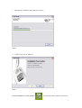
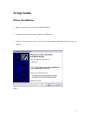
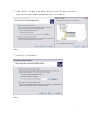
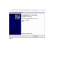
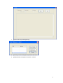
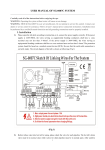
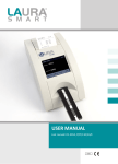
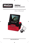
User’s Manual
M-CAM-C / M-CAM-D
PLEASE READ THIS MANUAL CAREFULLY BEFORE OPERATION
3, Hagavish st. Israel 58817 Tel: 972 3 5595252, Fax: 972 3 5594529
[email protected]
MRC.VER.01-03.12
Table of Contents
Computer specification....................................................................... 2
Setup Guide ........................................................................................ 3
Software Installation .................................................................................................................3
Driver Installation ...................................................................................................................6
Start................................................................................................... 10
Operating Interface .................................................................................................................10
One Key White Balance..................................................................................................11
Regional white balance ...................................................................................................11
Menubar ..................................................................................................................................15
Image Capture .........................................................................................................................18
Make dynamic capture to the present preview. ...............................................................19
Shadow Calibration Setting.............................................................................................20
Image Measurement................................................................................................................23
Albedo Measurement ..............................................................................................................26
Auto Count..............................................................................................................................30
Image Processing Functions....................................................................................................31
Report Function.......................................................................................................................33
Pathology Report.............................................................................................................33
Detection Report .............................................................................................................35
Solution of FAQ................................................................................ 40
1
Computer Specification:
The computer system needs to meet the following requirements
configuration
requirements
CPU
Intel intel core 2 duo E2140
Memory
2 GB
Available Hard Disk Capacity
1 GB
Display
17 inch(screen resolution 1280×1024,24/32 true color)
Operating System
Windows® XP,WIN7,VISTA
2
Software Installation
1. Place your CD into your CD-Rom/DVD-Rom.
2. Double-click
to bring out the installation dialogue box.
3. Click Next. (as on table 1)
Table 1
4. Choose I agree, and then click Next. (as on table 2)
Table 2
3
5. Click Next. (as on table 3)
Table 3
6. Choose" Install shortcut for current user only" and then click Next. (as on table 4)
Table 4
4
7. Wait until the installation will finish (as on table 5)
Table 5
8. Click Finish. (as on table 6)
Table 6
Finish installation. On the desktop
is generated, which could be clicked to run.
5
Setup Guide
Driver Installation
1. Place your CD into your CD-Rom/DVD-Rom.
2. Connect your camera to the computer’s USB port
3. Choose "Install from a list or specific location (advanced)"and click next. (as on
table 7)
Table 7
6
4. Click "Browse", navigate to the library drivers in your CD, choose the correct
driver for your camera model, and then click "OK". (as on table 8)
Table 8
5. Click "Next" ,(as on table 9)
Table 9
7
6. Click "Continue Anyway". (as on table 10)
Table 10
7. Wait until the installation will finish and then click "Next" (as on table 11)
Table 11
8
8. Click "Finish", finish the installation of camera driver. (as on table 12)
Table 12
9
Operating Interface
Start
1. Connect the camera to the computer.
2. Turn on the microscope light, and switch the light path into the camera.
3. Double-click
on the desktop to start the program.
4. Click Open Device in File list and choose devices, such as D300 of Mshot.
Preview the pictures of microscope in Main Window.
priory used to be opened by default.
Enable the devices
(as on table13/14)
Table 13
10
Table 14
5. Before observing a sample, you can adjust white balance first to avoid image
distortion.
One Key White Balance can intelligently adjust the image background to
pure white, and make the tone of image approach the effect watched via eyepiece.
When using, firstly the objects on the stage should be moved outside your visual field,
making the background of your visual field to be pure. Then click the One Key White
Balance in the left toolbar, after that, you can move the samples back. (As on the table
15/16)
Regional white balance:
remove the specimen off the FOV, then click
"Manual WB" button and select a white area in the FOV with mouse
Table 15
11
Before and After Comparison of White Balance:
Before white balance:
:
After white balance:
:
real-time image
↓
↓
Table 16
6. Extract [ Advance Setting] from the left toolbar, or click [View]-[Advance Image Setting], or
directly use the Shortcut Key [F7] to adjust the video parameters. Regarding the
adjustment of video parameters, please refer to the chapters illustrating image capturing in
the Manuel
(as on table 17/18)
Tabel 17
12
Table 18
7. Adjust resolution by clicking Resolution Setting in the left toolbar, clicking
View-Resolution Setting, or clicking F8. The camera always provides various
resolutions for different applications. For example, D300, which offers 3 kinds of
resolution including 640*480、1024*768 and 2048*1536, allows you select high resolution
when taking static photographs and middle or low resolution when taking videos.(as on table
19)
Table 19
13
8, Click
in the toolbar, enter save contents and names of the file, choose save format, and
click Confirm to save the present preview image. (as on table 20)
Table 20
14
Menu bar
When the program was in preview mode, all menu bars are operable. The opening of
functional modularity is controlled by hardware password.
Standard configuration ●
Main Menu
Tear-off Menu
functions
/adapted configuration○
○
New
New Dynamic Measurement or Report
Open
Open image and measurement data
Open device
Select image receiver
Save present preview pictures via select
File(F)
●
Save
directory, filename and file format
Export
Export measurement data
Close Document
Close present preview window
Exit
Exit program
Language setting
Choose program language
(F5)
(Chinese/English)
Calibrate picture elements, precision,
Option(O)
●
Calibration
etc.
Display present photo properties and so
Display
on
Capture pictures to catalogue set by
Acquire
●
Snap(F2)
auto photograph
Record Video(F4)
Start video recording function
Adjust relevant parameters of auto
Auto Snap Settings
capturing
Auto image cutting
Start Auto image cutting Settings
Settings
15
Standard configuration ●
Main Menu
Tear-off Menu
functions
/adapted configuration○
○
Shade Correction
Start Shadow Correction Setting
Setting
Start auto Snap
Start auto image capturing function
Stop Auto Snap
Close auto image capturing function
Enable Auto-focus
unopened
Enable Sensor
Temperature
unopened
Control
○
Auto-focus
unopened
settings
Temperature
unopened
Control Settings
Image enhance
Start Image Processing
●
Dynamic Measure
Measure dynamic image data
○
Static Measure
Measure static image data
●
Particle count model is started to deal
○
Auto Count
with present preview image
Advanced(A)
Report
Generate pathological reports
○
Test albedo of some material in core
Reflectivity
sample (this function to be used under
Measure
the condition of collocating with IF550
○
filter)
Image Splice
Joint Associated Pictures
WDM settings(F7)
Started when using WDM, applied to
●
View
video parameter setting
Resolution
Preview and capture image resolution
settings(R)
16
Standard configuration ●
Main Menu
Tear-off Menu
functions
/adapted configuration○
○
Zoom
Choose preview size (adaptive size/full
●
size 1:1)
Camera control
Start camera control model
●
Panel
Navigation view
When measuring images, it is used to
○
locate measuring spots
Measurement data
Start image parameter measurement
table
model
Toolbar
Choose window toolbar type
●
Status Bar
Show present device and status
●
Full Screen
Full Screen Preview
●
Cascading
Cascade preview window
Tile
Tile preview window
Arrange Icons
Arrange icons
Maximize
Maximize preview window
Minimize
Minimize preview window
Resize
Restore preview window
○
●
Window
Help
Show relevant information of program
●
17
Image Capture
1. In a preview, click Photograph in the left toolbar or choose Additional FunctionPhotograph, or directly click F2 to make static capture to the present preview image.
(as on table 21)
Table 21
2. After clicking Photograph, you should specify a directory path for the image. If you
capture image in Additional Function, the image will be directly saved to installation
folder Image. (as on table 22)
Table 22
18
Make dynamic capture to the present preview.
Select Video Recording in Additional Function, or directly click F3. The video
parameters could be set before recording. (as on table 23)
Table 23
Capture image by unceasingly taking photos of present preview. You can set the
photograph parameters in Additional Function-Auto Photograph Setting (remarks:
time interval should be more than 0). After finishing setting the parameters, choose
Open Auto Photograph to start and Close Auto Capturing to close. (as on table 24/25)
Table 24
Table 25
19
Shadow Calibration Setting
Calibrate the shadow in the current preview page. To calibrate in the condition that the central
part is brighter than other parts of the image.
Chart 26
For the over-bright central part, setting of the calibration parameters should be done prior to
the calibration.
1. Click [Acquire]-[ Shadow Calibration Setting] to enter the page of setting the shadow
calibration parameters (Chart 27):
Charter 27
20
2. Click [New Template] to enter template adding window (Chart 28, 29):
Chart 28
Chart 29
3. Click [Snap] from [Video Source] to enter video source selection, select current video
source. (Chart 30)
Chart 30
21
4. After selection, click [Snap] to snapshot the current image, and enter the remarks name in
Template Name. (Chart 31)
Notes;Before the image capturing, you should adjust focal distance and move samples
away. The template should be pictures of blank sample.
Chart 31
5. Click [Enter] →select region of appropriate brightness→[Confirm], and then template is
added successfully. (Chart 32)
Chart 32
22
6. Select designed template in checkbox and click [Confirm] to finish parameter setting. After
completing the shadow calibration, there is no bright speck in the photos. (Chart 33)
Before calibration
After calibration
Chart 33
Image Measurement
1
Make dynamic/static measurement on the preview page. Select [Advanced]-[Dynamic/Static
measurement]. Above the navigation bar standing on the left of Chart 40 is the position
navigation, and the below is the longitude and latitude navigation of the place where mouse
points. (as on table 34, 35)
Table 34
23
Table 35
2 . Measure Add Area
Measuring tool in toolbar can be used to measure the objective. Choose
Option-Calibration to measure magnification. Introduce the tools in toolbar as
follows. When deleting the measurement tools placed, you can pick the objectives and
Editor-Delete. When adjusting measuring tools, firstly you can click the tool picked
and then plot a region in the picture to be measured.
[Insert Rulers] standard proportional scale
[Insert Gauge Point] locate x, y coordinate of target point
[Insert Line Segment] measure the distance between two target points
[insert rectangle] left click to mark the diagonal points of the rectangle and measure the
length, width, size and perimeter.
[insert circle] left click to mark 3 points on the circumference and measure radius,
perimeter and size.
[insert ellipse] left click to mark the diagonal points of enclosing rectangle and measure
the long diameter, short diameter, perimeter and size.
[insert curve] press and hold down the left key to mark the key points of the curve and
measure the length.
[insert hand-sketched region] press and hold down the left key to mark the key points on
24
the circumference and measure the perimeter and size.
[insert polygon] left click to orderly mark the corners of polygon and measure the
perimeter and size.
[Insert Angle] mark angle
[Select] select tools has been used to measure
3. Calibrate Survey scale
After clicking
, the setting window popup (as on table 36). When setting
parameters, you can choose unit: px、cm、mm、um. When filling name allocation,
name modification could choose Option-Calibration in the menu, and modify the
allocation name (as on table 37)
Table 36
Table 37
25
4. Save data
Choose File-Save Pictures
, and then the pictures including measurement data
can be obtained.
Choose File-Save Data, and then the excel file including measurement data can be
obtained.
Albedo Measurement
1. Save data
After starting MShot Digital Imaging System, open the image input device (please refer to
Start MShot Digital Imaging System).
In Application menu, choose albedo Measurement to deal with the present preview
image, or Start albedo Measurement
, start albedo measurement model, make use
of the submenu Open in the model, and enter the image file to be handled. Take the
below demo. jpg for example. (As on table 38)
26
Table 38
2. Standardization
Click menu bar
or choose Editor-Add Area-Reference, choose the NO. of
reference point saved and standard albedo ratio, click Confirm. Click the upper-left
corner and bottom-right corner of the region in the picture to select standard area.
Operate repetitively to make standard points as many as possible. The software will
standardize the regression curve and give relevant parameters according to the
average gray-scale value of this region.
Albedo ration □ coefficient A□ grayscale □ coefficient B
3. Modify Standardization
Click setting to modify the standard points marked. (As on table 39)
27
Table 39
4. Measurement
Add measurement area. You can make use of toolbar
irregular region,
polygon and
to select
rectangle.
5. Preview table. Choose Operation-Preview Table to preview inputted data and table.
(As on table 40)
Table is a histogram, indicating mark off statistics area according to the size of
grouped region appointed and calculates the proportion of sample number per region
to the total amount. Right click the histogram to delete cylindricality.
Note: when previewing a table, please appoint a region at first. The corresponding
rectangles will be deleted at the same time when deleting the cylindricality.
Table 40
28
6. Modify parameters. Preview relevant parameters of the table, including True Type,
color, grouped region, etc. all of which can be modified in Option-Setting. (As on
table 41)
Table 41
7. Output data.
Choose File-Export Data to get excel reports that consist of data and table. (Table 42)
Table 42
29
Auto Count
1. Number the particles of preview image. Choose Application-Auto number, (as on
table 43)
Table 43
2. Menu bar will change as shown below. Click Counting Function, and choose Start
Counting. (as on table 44)
Table 44
3. Appoint counting parameters, and then click Counting. The result will show on the
dialogue box directly. The size of counting points and their coordinates will also
appear in the preview. (as on table 45)
Remarks:
(1) the bigger the histogram threshold is, the more the white pixels transformed will
appear in the image.
(2) Software will only count the white object, and will select Opposition when the
object displayed is black.
(3) The greater the minimum area value per object entered is, the bigger the point area
that to be counted will be.
30
(4) The size of the region is to be counted according to the pixel, entering 20-50
means screening a region ranging from 20 pixels to 50 pixels, but simply omitting
the other regions, and export the amount of the regions in the end.
Table 45
Image Processing Functions
1. Handle the present pictures by opening a picture in File or clicking
2. Choose Image-Image Processing/Image Enhancement, and then handle or select
the image according to the demand. (as on table 46)
Table 46
When choosing Brightness/Contrast Adjustment, a dialogue box popup (as on table
47). The bigger the brightness value is, the brighter the image will be; the greater the
contrast value is, the higher contrast of color will be.
31
Table 47
When choosing Tone/Saturation Contrast, a dialogue box popup (as on table 48). The
bigger the tone value is, the more bright-colored the image will be; the greater the
saturation value is, the deeper the color of the image will be.
Table 48
3. After save the image processing by clicking
, you can click Return to Original Picture to
rehandle the image. (as on table 49)
Table 49
32
Report Function
Pathology Report
1. Generate reports from the preview, and set up files. Choose Applications-Reports.
(as on table 50)
Table 50
2. Enter information about the preview image. The following picture is the example
of maternal and child health clinic. (as on table 51)
Table 51
33
3. Add or save recordings. After setting the picture path, click Add Recording or
Save Recording directly. You can also print the reports. (as on table 52)
Table 52
4. After saving the recordings, you can click Information of All Zeros directly to add new records,
and then return to the first operation.
34
Detection Report
Basic reporting operation
1.
Select Detection report function.
2.
Enter user name & password in the dialog box and click [Confirm]. Notes: initial user
name is root, password is 12345.
1.
Reporting function can be realized. Interface is as follows:
2.
Click [New Report], add report data.
35
3.
Enter parameters of the sample added, click [Snap] to capture sample image.
4.
Click [Add Data] to record data of sample.
5.
After finishing adding dada, click [Finish]. If you want to add a new recording, back to
the step 1.
6.
If you want to check data, click [Edit] from data list, or double click [View Details].
7.
If you want to edit or delete data, click [Edit Report] or [Delete Report] in the selected
report.
Query Operation
1.
In the Query Operation Workgroup, make a query on report by entering single or more
query conditions.
36
2.
After confirm the query conditions, click [Query]
3.
After querying, only matched report data shown in the report recording list. Click [Full
Display], and then all report data will be displayed.
Administrator Operation (administrator only)
1.
Click [Admin] to enter administration control panel.
2.
Administrator can manage report users.
1.
[Add Users]: could manage users and set permission.
2.
[Delete Users]: could delete current users.
3.
[Modify User Password]: modify the password of the selected users.
37
4.
[Reset User Password]: reset the password of selected users.
5.
[Modify User Permission]: modify the permission of users
6.
[View Log]: view operation recording of users.
38
7.
[Inspector/Surveyor Management]:
8.
[Confirm]: confirm management operation, and exit.
9.
[Delete]: delete management operation, and exit.
39
Solution of FAQ
Question
Phenomenon
Solutions
No.
Start by using administrator account, or
setup.bat
can’t
be
started
under
start command mode by using
1
Vista\Windows 7,user check fail。
administrator account, carry out
setup.bat
Please
close
image
processing
software, install camera driver first. In
3
No devices on the device listing
case of installation of driver, please
solve problems in 4 methods according
to the questions.
( 1 ) make sure camera has been
connected to USB2.0 port.
Fail after selecting video devices,
4
RasMan initialization failure.
( 2 ) pull out the USB2.0 port,
re-connect and re-start. If fail again,
please change to the other USB port
(the USB port behind the host computer
is recommended in case of desktop)
40
Question
Phenomenon
Solutions
No.
(1)if the microscope is a kind of rod
beam-splitting microscope, please
pull the rob to the digital imaging
equipment.
After opening the capturing window,
(2)please adjust adjustment knob of
5
the image window is in darkness.
micro
lamb
to
raise
the
brightness of lamb.
( 3 ) please solve problems in 4
methods
according
to
the
questions.
( 1 ) the illuminator is over bright,
please lower the brightness of the lamp.
(2)open 2 video capturing at the same
After opening the capturing window,
6
the image window is brilliant white.
time, after closing capturing software,
open one of them.
(3)insert camera into USB1.1 port,
exchange computer.
The tone and color of preview picture
7
Please adjust white balance, refer to the
in image window is largely different
part
about
from that observed via eyepieces.
manual.
image
capturing
in
41
Question
Phenomenon
Solutions
No.
Because of the smaller size of sensor,
8
The visual field of preview image in
this phenomenon is usual. In case of
image window is much smaller than
needing bigger visual field, please
that observed in the eyepieces.
contact us for selecting 0.5X port,
0.63X PORT.
(1)the aperture is too big, please
close it properly.
9
Image blurring
(2)when the eyepieces and camera
are out of step, clarities don’t occur
at the same time, please adjust the
synchrony of C port.
The exposure period is too short, please
Collocated with stereo microscope,
change into manual exposure and
jerky video appears.
lower the grain to add exposure
10
time.
42