1
9010A Language
Compilar
�
P/N 661 504
December 1 983
C1983 John Fluke Mfg. Co., lnc.,
all rights reservad. Litho in U.S.A.
NOTICE
This manual describes u n p u b l ished Software which contains the trade secrets
and confidential p roprietary information of John F l uke Mfg. Co., l nc. and
which em bodies su bstantial c reative effort, ideas, and expressions. THE
SOFTWAR E IS PROVIDED UN DER LICENSE FROM FLUKE. F l uke g rants
Licensee a perpetua! non-excl us i ve l icense to use this material and make up to
three copies for backup p u rposes without written permission from F l uke.
THIS SOFTWARE IS LICENSED FOR USE ON A SINGLE COM PUTER
S YSTEM.
LIMITED WARRANTY
F l uke warrants that the Software has been p roperly recorded on non-defectiva
d iskettes. Fl uke does not warrant the Software to be e rror free. F l u ke will
replace such d iskettes without charge if F l u ke in good faith determines that
such d iskettes were not su bject to m isuse and if returned to a F l uke Technical
Service Center, within n inety (90) days of shi pment. Refer to you r 901 0A
Operator M anual for a l isting of locations. Fluke reserves the right to change
the specifications and operating characteristics of the Software it prod uces,
over a period of time, without notice.
FLUKE GRANTS NO OTHER WARRANTIES, EITHER EXPRESSE D OR
IM PLIED, INCLUDING ANY IM PLIED WARRANTIES OF M ERCHANTABIL
ITY OR FITNESS FOR A PARTICULAR PURPOSE OR USE. IN NO EVENT
SHALL FLUKE BE LIABLE FOR ANY LOSS OF DATA, USE, PROFITS OR
GOODW I L L , OR F OR D IR E CT, IN D IR E CT, S P E C IA L , IN C ID ENTAL,
CONSEQUENTIAL OR OTHER SIM ILAR DAMAGES AS A R ESULT OF ANY
MATTER R ELATED TO THIS AGREEM ENT, R EGARDLESS OF THE FORM
OF THE ACTION.
Copyright (©)1 983 John F l uke Mfg. Co., l nc.,
P.O. Box C9090, Everett, Washington 98206
··�
Contents
1
I NTRODUCTION ............................... 1 -1
I ntroduction to the 90 1 0A Language Compiler . . . . . . . . . .
The Host Computer System . . . . . . . . . . . . . . . . . . . . . . . . . . .
............................
How the Compiler W orks
Language Extensi ons . . . . . . . . . . . . . . . . . . . . . . . . . . . . . . . . . .
The 90 1 0A Language Compi ler Package . . . . . . . . . . . . . . . .
Di sk Verification Program . . . . . . . . . . . . . . . . . . . . . . . . . .
Compiler . . . . . . . . . . . . . . . . . . . . . . . . . . . . . . . . . . . . . . . . .
Fi le Transfer Program . . . . . . . . . . . . . . . . . . . . . . . . . . . . .
Pod Data Files . . . . . . . . . . . . . . . . . . . . . . . . . . . . . . . . . . . .
Use With the 9005A . . . . . . . . . . . . . . . . . . . . . . . . . . . . . . . . . .
1 -3
1 -4
1 -5
1 -6
1 -7
1 -7
1 -7
1 -7
1 -8
1 -8
HOW TO USE THIS MANUAL
2-1
.
.
.
.
.
.
.
.
2
Introduction
Organization . . . . . . . . . . . . . . . . . . . . . . . . . . . . . . . . . . . . . . . .
S uggested U se . . . . . . . . . . . . . . . . . . . . . . . . . . . . . . . . . . . . . . .
.
3
.
.
.
.
.
.
.
.
.
.
.
.
.
.
.
.
.
.
.
.
.
.
.
.
.
.
.
.
.
.
.
.
.
.
.
.
.
.
.
.
.
.
2-3
2-4
2-5
GETTI NG STARTED ........................... 3-1
I ntroduction . . . . . . . . . . . . . . . . . . . . . . . . . . . . . . . . . . . . . . . .
Fluke 1 72CA Instrument Controller . . . . . . . . . . . . . . . . . . . .
Introduction . . . . . . . . . . . . . . . . . . . . . . . . . . . . . . . . . . . . . .
What Y o u N eed . . . . . . . . . . . . . . . . . . . . . . . . . . . . . . . . . . .
Backing U p the Program Di skette
"......
.....................
Verifyi ng the W orking Diskette
Hooking Up the System
.
S ystem Dependencies . . . . . . . . . . . . . . . . . . . . . . . . . . . . . .
Test Editor . . . . . . . . . . . . . . . . . . . . . . . . . . . . . . . . . . . . .
Disk Space . . . . . . . . . . . . . . . . . . . . . . . . . . . . . . . . . . . . .
Compiler Organization . . . . . . . . . . . . . . . . . . . . . . . . . . .
.
.
.
.
.
.
.
.
.
.
.
.
.
.
.
.
.
.
.
.
.
.
.
.
.
.
.
.
.
.
.
.
.
.
.
.
.
.
.
.
.
.
.
.
.
.
.
.
.
.
3-3
3-4
3-4
3-4
3-4
3-5
3-6
3-8
3-8
3-8
3-8
(continued on page ii)
CONTENTS, continued
Fluke 1 722A Instrument Controller . . . . . . . . . . . . . . . . . . . . .
I ntroduction . . . . . . . . . . . . . . . . . . . . . . . . . . . . . . . . . . . . . . .
What Y ou N eed . . . . . . . . . . . . . . . . . . . . . . . . . . . . . . . . . . . .
Backing U p the Program Diskette . . . . . . . . . . . . . . . . . . . .
Verifying the W orking Diskette . . . . . . . . . . . . . . . . . . . . . .
Hooking Up the System . . . . . . . . . . . . . . . . . . . . . . . . . . . . .
System Dependencies . . . . . . . . . . . . . . . . . . . . . . . . . . . . . . .
Text Editor . . . . . . . . . . . . . . . . . . . . . . . . . . . . . . . . . . . . . .
Disk Space . . . . . . . . . . . . . . . . . . . . . . . . . . . . . . . . . . . . . .
I B M Personal Computer . . . . . . . . . . . . . . . . . . . . . . . . . . . . . .
Introduction . . . . . . . . . . . . . . . . . . . . . . . . . . . . . . . . . . . . . . .
What You Need
Backing U p the Program Diskette . . . . . . . . . . . . . . . . . . . .
Verifying the Working Diskette . . . . . . . . . . . . . . . . . . . . . .
H ooking U p the System . . . . . . . . . . . . . . . . . . . . . . . . . . . . .
System Editor . . . . . . . . . . . . . . . . . . . . . . . . . . . . . . . . . . . . . .
RETURN Key . . . . . . . . . . . . . . . . . . . . . . . . . . . . . . . . . . . . .
CP j M Operating Systems . . . . . . . . . . . . . . . . . . . . . . . . . . . . .
Introduction . . . . . . . . . . . . . . . . . . . . . . . . . . . . . . . . . . . . . . .
What You Need . . . . . . . . . . . . . . . . . . . . . . . . . . . . . . . . . . . .
Backing Up the Program Diskette . . . . . . . . . . . . . . . . . . . .
V erifying the W orking Diskette . . . . . . . . . . . . . . . . . . . . . .
Hooking Up the System . . . . . . . . . . . . . . . . . . . . . . . . . . . . .
lnstaUing Software . . . . . . . . . . . . . . . . . . . . . . . . . . . . . . . . .
Editor . . . . . . . . . . . . . . . . . . . . . . . . . . . . . . . . . . . . . . . . . . . .
.
4
.
.
.
.
.
.
.
.
.
.
.
.
.
.
.
.
.
.
.
.
.
.
.
.
.
.
.
.
.
.
.
.
.
.
.
3-9
3-9
3-9
3-9
3-1 O
3-10
3-12
3-12
3-12
3-1 3
3-13
3-1 3
3-14
3-14
3-1 5
3-1 6
3-16
3-17
3-17
3-17
3-1 8
3-18
3-1 9
3-20
3-20
WRITING PROGRAMS ......................... 4-1
Introduction . . . . . . . . . . . . . . . . . . . . . . . . . . . . . . . . . . . . . . . . .
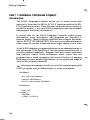
Part 1 : General Program Format . . . . . . . . . . . . . . . . . . . . . . .
lntroduction . . . . . . . . . . . . . . . . . . . . . . . . . . . . . . . . . . . . . . .
I mportant Details . . . . . . . . . . . . . . . . . . . . . . . . . . . . . . . . . .
Program Comments . . . . . . . . . . . . . . . . . . . . . . . . . . . . . . . .
90 1 0A Programs . . . . . . . . . . . . . . . . . . . . . . . . . . . . . . . . . . .
Address Space Information . . . . . . . . . . . . . . . . . . . . . . . . . .
Setup Information . . . . . . . . . . . . . . . . . . . . . . . . . . . . . . . . . .
Pod Data Files . . . . . . . . . . . . . . . . . . . . . . . . . . . . . . . . . . . . .
90 1 0A/ Pod Interaction . . . . . . . . . . . . . . . . . . . . . . . . . . . . . .
Sample Program . . . . . . . . . . . . . . . . . . . . . . . . . . . . . . . . . . .
Part 2: Coding Shortcuts . . . . . . . . . . . . . . . . . . . . . . . . . . . . . .
Introduction . . . . . . . . . . . . . . . . . . . . . . . . . . . . . . . . . . . . . . .
Optional Keywords and Keyword Abbreviations . . . . . . . .
U nary Operator Shorthand . . . . . . . . . . . . . . . . . . . . . . . . . .
Default Entries . . . . . . . . . . . . . . . . . . . . . . . . . . . . . . . . . . . . .
File lnclusion . . . . . . . . . . . . . . . . . . . . . . . . . . . . . . . . . . . . . .
(continued on page iii)
ii
4-3
4-4
4-4
4-5
4-7
4-8
4-8
4-9
4-1 1
4-1 2
4-1 3
4-1 6
4-1 6
4-1 7
4-1 8
4-1 8
4-1 9
CONTENTS, continued
Sample Program . . . . . . . . . . . . . . . . . . . . . . . . . . . . . . . . . . .
Part 3 : Symbolic Names . . . . . . . . . . . . . . . . . . . . . . . . . . . . . . .
Introduction . . . . . . . . . . . . . . . . . . . . . . . . . . . . . . . . . . . . . . .
Symbolic Program Names . . . . . . . . . . . . . . . . . . . . . . . . . . .
S ymbolic Labels . . . . . . . . . . . . . . . . . . . . . . . . . . . . . . . . . . . .
Symbolic Register Names . . . . . . . . . . . . . . . . . . . . . . . . . . . .
Predefined Register N ames . . . . . . . . . . . . . . . . . . . . . . . . . .
Sample Program . . . . . . . . . . . . . . . . . . . . . . . . . . . . . . . . . . .
5
4-20
4-22
4-22
4-24
4-26
4-28
4-29
4-30
USING THE COMPI LER ........................ 5-1
lntroduction . . . . . . . . . . . . . . . . . . . . . . . . . . . . . . . . . . . . . . . . .
Preparing the S ource File . . . . . . . . . . . . . . . . . . . . . . . . . . . . . .
Compiling . . . . . . . . . . . . . . . . . . . . . . . . . . . . . . . . . . . . . . . . . . .
Interactive Mode . . . . . . . . . . . . . . . . . . . . . . . . . . . . . . . . . . .
Command Line Mode . . . . . . . . . . . . . . . . . . . . . . . . . . . . . .
Listing File Options . . . . . . . . . . . . . . . . . . . . . . . . . . . . . . . .
Syntax Errors . . . . . . . . . . . . . . . . . . . . . . . . . . . . . . . . . . . . . .
Transferring Programs . . . . . . . . . . . . . . . . . . . . . . . . . . . . . . . .
Transferring Programs t o the 901 0A . . . . . . . . . . . . . . . . . .
Transferring Programs from the 90 1 0A . . . . . . . . . . . . . . . .
Source Format . . . . . . . . . . . . . . . . . . . . . . . . . . . . . . . . . . . . .
Hex Format . . . . . . . . . . . . . . . . . . . . . . . . . . . . . . . . . . . . . . .
6
5-3
5-4
5-5
5-6
5-8
5-10
5-1 1
5-1 2
5-1 2
5-14
5-14
5-1 6
LANGUAGE REFERENCE ...................... 6-1
Introduction . . . . . . . . . . . . . . . . . . . . . . . . . . . . . . . . . . . . . . . . .
Syntax Diagram N otation . . . . . . . . . . . . . . . . . . . . . . . . . . . . .
Special Symbols . . . . . . . . . . . . . . . . . . . . . . . . . . . . . . . . . . . . . .
Symbolic Names . . . . . . . . . . . . . . . . . . . . . . . . . . . . . . . . . . . . .
Expressions . . . . . . . . . . . . . . . . . . . . . . . . . . . . . . . . . . . . . . . . . .
Addresses . . . . . . . . . . . . . . . . . . . . . . . . . . . . . . . . . . . . . . . . . . . .
General l nformation . . . . . . . . . . . . . . . . . . . . . . . . . . . . . . . . . .
Statement Format . . . . . . . . . . . . . . . . . . . . . . . . . . . . . . . . . . . .
Program Comments . . . . . . . . . . . . . . . . . . . . . . . . . . . . . . . . . .
File lnclusion . . . . . . . . . . . . . . . . . . . . . . . . . . . . . . . . . . . . . . . .
6-3
6-4
6-5
6-6
6-8
6-1 O
6-1 1
6-1 1
6-1 1
6-12
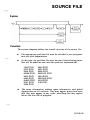
SOURCE FILE SYNTAX ...... . ..... . . . ...... . .
6-1 3
.
S ource File . . . . . . . . . . . . . . . . . . . . . . . . . . . . . . . . . . . . . . . . . .
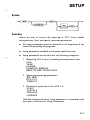
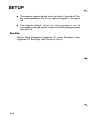
Setup
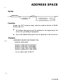
Address Space . . . . . . . . . . . . . . . . . . . . . . . . . . . . . . . . . . . . . . .
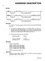
Address Descriptor . . . . . . . . . . . . . . . . . . . . . . . . . . . . . . . . . . .
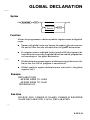
Global Declaration . . . . . . . . . . . . . . . . . . . . . . . . . . . . . . . . . . .
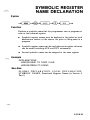
Symbolic Register Name Declaration . . . . . . . . . . . . . . . . . . . .
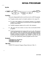
90 1 0A Program . . . . . . . . . . . . . . . . . . . . . . . . . . . . . . . . . . . . . .
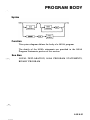
Program Body . . . . . . . . . . . . . . . . . . . . . . . . . . . . . . . . . . . . . . .
.
.
.
.
.
.
.
.
.
.
.
.
.
.
.
.
.
.
.
.
.
¡¡¡
.
.
.
.
.
.
.
.
.
.
.
.
.
.
.
.
.
.
.
.
.
.
.
.
.
.
6-1 5
6-1 7
6-1 9
6-2 1
6-23
6-25
6-27
6-29
(continued on page iv)
CONTENTS, continued
·�
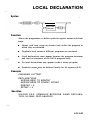
Local Declaration . . . . . . . . . . . . . . . . . . . . . . . . . . . . . . . . . . . 6-3 1
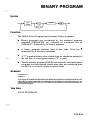
Binary Program . . . . . . . . . . . . . . . . . . . . . . . . . . . . . . . . . . . . . 6-33
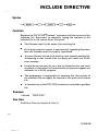
Include Directive . . . . . . . . . . . . . . . . . . . . . . . . . . . . . . . . . . . . . 6-35
.
.
SETUP PARAMETERS ......................... 6-37
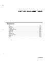
Beep .
.
. ...
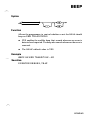
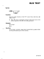
Bus Test . . . . . . . . . . . . . . . . . . . . . . . . . . . . . . . . . . . . . . . . . . . .
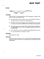
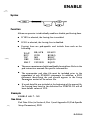
Enable . . . . . . . . . . . . . . . . . . . . . . . . . . . . . . . . . . . . . . . . . . . . .
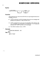
Exercise Errors . . . . . . . . . . . . . . . . . . . . . . . . . . . . . . . . . . . . . .
Linesize . . . . . . . . . . . . . . . . . . . . . . . . . . . . . . . . . . . . . . . . . . . .
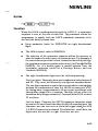
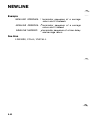
Newline . . . . . . . . . . . . . . . . . . . . . . . . . . . . . . . . . . . . . . . . . . . .
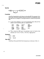
Pod
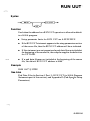
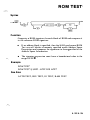
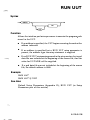
Run UUT . . . . . . . . . . . . . . . . . . . . . . . . . . . . . . . . . . . . . . . . . .
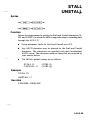
Stallj Unstall . . . . . . . . . . . . . . . . . . . . . . . . . . . . . . . . . . . . . . . .
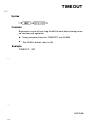
Timeout . . . . . . . . . . . . . . . . . . . . . . . . . . . . . . . . . . . . . . . . . . . .
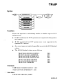
Trap
.
.
.
.
.
.
.
.
.
.
.
.
.
.
.
.
.
.
.
.
.
.
.
.
.
.
.
.
.
.
.
.
.
.
.
.
.
.
.
.
.
.
.
.
.
.
.
.
.
.
·
.
.
·
.
·
.
.
·
.
.
·
.
.
·
·
.
.
·
.
·
·
.
·
·
.
·
·
.
·
.
·
·
.
·
·
.
·
·
·
·
·
·
·
·
·
·
·
·
·
·
·
·
·
·
·
·
·
·
·
·
·
·
·
·
·
·
·
·
·
·
·
·
·
·
·
·
·
·
·
·
·
·
·
·
·
901 0A PROG RAM STATEM ENTS ..............
.
.
.
.
.
.
.
.
.
.
.
.
.
.
.
.
.
.
.
.
.
.
.
.
.
.
.
.
.
.
.
.
.
.
.
.
.
.
.
.
.
,
.
.
.
.
.
.
.
.
.
.
.
.
.
.
.
.
.
.
.
.
.
.
.
.
.
.
.
.
.
.
.
.
.
.
.
.
.
.
.
.
.
.
.
.
.
.
.
.
.
.
.
·
.
.
.
·
.
.
.
·
.
.
·
.
.
. ·.
·
.
.
.
·
.
.
.
·
.
.
.
·
.
·
.
·
.
·
.
·
.
.
.
·
.
.
.
·
.
·
.
·
.
·
.
·
.
·
.
·
.
·
.
·
.
·
.
·
.
·
.
·
.
·
.
·
.
·
.
·
.
·
.
·
.
·
.
·
.
·
.
.
.
.
.
·
.
.
.
·
·
.
·
.
·
.
.
.
.
.
.
.
.
.
.
.
.
.
.
·
.
.
.
.
.
.
.
.
.
.
.
.
.
.
.
.
.
.
.
.
.
.
.
.
.
.
.
.
.
.
.
.
.
.
.
.
.
.
.
.
.
.
.
.
.
·
·
·
·
·
·
·
·
·
.
.
.
.
.
.
.
.
.
.
.
.
.
.
.
.
.
.
.
.
.
.
.
.
.
.
.
.
.
.
.
.
.
.
.
.
.
·
·
·
.
·
·
.
.
·
·
(continued on page v)
iv
6-39
6-4 1
6-43
6-45
6-47
6-49
6-5 1
6-53
6-55
6-57
6-59
6-61
.
Atog
Auto Test . . . . . . . . . . . . . . . . . . . . . . . . . . . . . . . . . . . . . . . . . .
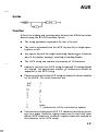
Aux . . . . . . . . . . . . . . . . . . . . . . . . . . . . . . . . . . . . . . . . . . . . . . .
Bus Test . . . . . . . . . . . . . . . . . . . . . . . . . . . . . . . . . . . . . . . . . . . .
Dpy . . . . . . . . . . . . . . . . . . . . . . . . . . . . . . . . . . . . . . . . . . . . . . .
Dtog . . . . . . . . . . . . . . . . . . . . . . . . . . . . . . . . . . . . . . . . . . . . . . .
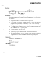
Execute . . . . . . . . . . . . . . . . . . . . . . . . . . . . . . . . . . . . . . . . . . . .
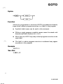
Goto . . . . . . . . . . . . . . . . . . . . . . . . . . . . . . . . . . . . . . . . . . . . . . .
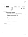
If
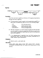
10 Test . . . . . . . . . . . . . . . . . . . . . . . . . . . . . . . . . . . . . . . . . . . .
Label . . . . . . . . . . . . . . . . . . . . . . . . . . . . . . . . . . . . . . . . . . . . . .
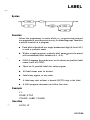
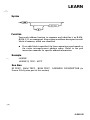
Learn . . . . . . . . . . . . . . . . . . . . . . . . . . . . . . . . . . . . . . . . . . . . . .
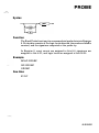
Probe . . . . . . . . . . . . . . . . . . . . . . . . . . . . . . . . . . . . . . . . . . . . . .
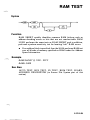
RAM Test . . . . . . . . . . . . . . . . . . . . . . . . . . . . . . . . . . . . . . . . . .
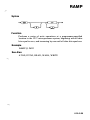
RAMP . . . . . . . . . . . . . . . . . . . . . . . . . . . . . . . . . . . . . . . . . . . . .
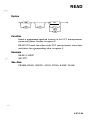
Read
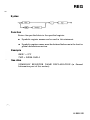
Reg . . . . . . . . . . . . . . . . . . . . . . . . . . . . . . . . . . . . . . . . . . . . . . . .
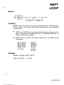
Reptj Loop
ROM Test . . . . . . . . . . . . . . . . . . . . . . . . . . . . . . . . . . . . . . . . . .
Run UUT . . . . . . . . . . . . . . . . . . . . . . . . . . . . . . . . . . . . . . . . . .
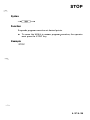
Stop . . . . . . . . . . . . . . . . . . . . . . . . . . . . . . . . . . . . . . . . . . . . . . .
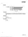
Sync . . . . . . . . . . . . . . . . . . . . . . . . . . . . . . . . . . . . . . . . . . . . . . .
Unary . . . . . . . . . . . . . . . . . . . . . . . . . . . . . . . . . . . . . . . . . . . . . .
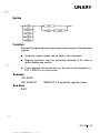
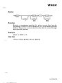
Walk
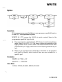
Write
.
·
.
6-63
6-65
6-67
6-7 1
6-73
6-77
6-79
6-8 1
6-83
6-85
6-87
6-89
6-9 1
6-93
6-95
6-97
6-99
6-1 0 1
6-1 03
6-1 05
6-1 07
6-1 09
6-1 1 1
6-1 1 3
6-1 1 5
......
CONTE NTS, continued
APPENDICES
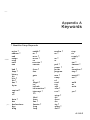
A Keywords .
.
.
.
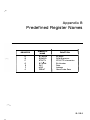
B Predefined R egister N ames . . . . .
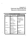
C Optional Keywords and Keyword
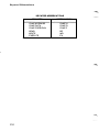
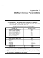
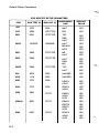
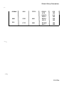
D Default Setup Parameters . . . . . .
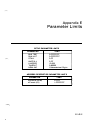
E Parameter Limits . . . . . . . . . . . . . .
F Error Messages
.
.
.
.
.
.
.
.
.
.
.
.
.
.
.
.
.
.
.
.
.
.
.
I NDEX
vtvi
.
.
.
.
.
.
.
.
.
.
.
.
.............
Abbreviations
.............
.............
.
..
.
..
..
...
...
...
...
.
.
.
.
.
.
.
.
.
.
.
.
.
.
.
.
.
.
.
.
.
.
.
.
.
.
.
.
.
.
.
.
.
.
.
.
.
.
.
.
.
.
.
A-1
B-1
C-1
D-1
E-1
F-1
Section 1
1 ntroduction
CONTENTS
I ntroduction to the 90 1 0A Language Compiler . . . . . . . . . . .
The Host Computer System . . . . . . . . . . . . . . . . . . . . . . . . . . . .
H ow the Compiler Works
Language Extensions . . . . . . . . . . . . . . . . . . . . . . . . . . . . . . . . . .
The 901 0 A Language Compi1er Package . . . . . . . . . . . . . . . . .
Disk V erification Program . . . . . . . . . . . . . . . . . . . . . . . . . . .
Compiler . . . . . . . . . . . . . . . . . . . . . . . . . . . . . . . . . . . . . . . . . .
File Transfer Program . . . . . . . . . . . . . . . . . . . . . . . . . . . . . .
Pod Data Files . . . . . . . . . . . . . . . . . . . . . . . . . . . . . . . . . . . . .
Use With the 9005A . . . . . . . . . . . . . . . . . . . . . . . . . . . . . . . . . .
.
.
.
.
.
.
.
.
.
.
.
.
.
.
.
.
.
.
.
.
.
.
.
.
.
.
.
.
.
1 -3
1 -4
1 -5
1 -6
1 -7
1 -7
1 -7
1 -7
1 -8
1 -8
1 -1 /1 -2
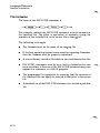
I NTRODUCTION TO THE 901 0A LANGUAGE COMPILER
The 901 0A Language Compiler package is used to create test and
troubleshooting programs for the Fluke 90 1 0A M icro-System
Troubleshooter.
The 90 1 0A is an excellent tool for interactive troubleshooting, and
many users may want to take advantage of its power by writing
extensive test programs. While the 90 1 0A itself is very convenient for
entering relatively short programs, it may be advantageous to create
and maintain large, elaborate, or complex programs using a host
computer's editing and file management facilities. The 90 1 0A
Language Compiler allows 90 l OA programs to be developed
conveniently on a host computer system and then transferred to the
901 0 A for execution.
1 -3
l ntroduction
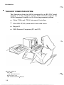
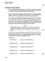
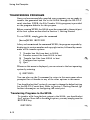
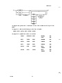
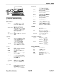
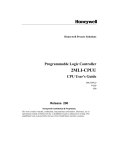
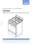
THE HOST COMPUTER SYSTEM
The illustration shows the 90 l OA connected by an RS-232-C serial
interface to a host computer system. Fluke currently supports the
90 1 0A Language Compiler on the fol l owing computer systems:
•
Fl uke 1 720A and 1 722A Instrument Controllers
•
M ost Z80 CP 1 M systems with 8-inch disk drives
•
Kaypro 1 1
•
IBM Personal Computers (PC and XT)
··�
Registered Trademarks:
Z-80: Zilog
CP/M: Digital Research Inc.
Kaypro: Kaypro Corp.
IBM: Intemational Business Machines
1 -4
1 ntroduction
HOW THE COMPI LER WORKS
The 90 1 OA is able to read and write test programs via its auxiliary RS232-C interface. The entire contents of the 90 1 OA program memory,
including setup parameters and address space descriptors, are
transferred through the serial interface in a special hex data format.
The 90 1 0A Language Compiler takes advantage of this ability of the
90 1 0A to read programs in hex format.
The test programmer develops the test programs on the host computer
systeni in an ASCII source program form using the full power of the
editing and file storage capabilities of the host system. In this sense, a
90 1 0A program on the host system is much like a program written in
any other programming language, such as BASI C, FORTRAN, or
Pascal.
Once the program has been written in so urce form, the 90 l OA
Language Compiler program converts the so urce program into the hex
format required for transfer to the 90 1 0A.
The program is then transferred to the 90 1 OA using a transfer program
that is supplied with the compiler package, and the hex format
program is read into Troubleshooter memory by pressing the AUX
1/ F and READ keys on the 901 O A.
1 -5
l ntroduction
LANGUAG E EXTENSIONS
The 90 1 0A Language Compiler accepts any program that can be
ente red through the 90 1 OA keyboard. In fact, the syntax of the 90 1 OA
Language is compatible with program listings obtained from the
90 1 0A using the AUX 1 / F SETUP, AUX 1 / F LEARN, and AUX 1/F
PROGM commands described in the 90 1 0A Operator Manual.
In addition to the standard 90 1 0A commands, however, the 90 10A
Language Compiler provides sorne powerful extensions . These
additional features are designed to make it much easier to develop and
maintain large 90 1 0A programs. Sorne of the key features are:
1 -6
•
Program Comments
Allows the test programmer to
incorporate documentation into
the program itself
•
Keyword Abbreviations, Op
tional Command Keywords,
and Shorthand N otation for
Unary Operators
Minimizes the typing required to
enter a test program on the host
system
•
File Inclusion
Permits common programs to
be conveniently shared by many
source files, reducing the time
required t o develop test
programs for new applications
•
Symbolic Names for Programs,
Labels, and Registers
Allow programs to be written
more clearly, making t hem
e a s i e r to u n d e r s t a n d a n d
maintain
l ntroduction
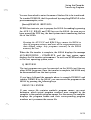
THE 901 0A LANGUAGE COMPILER PACKAGE
The 901 0A Language Compiler package consists of this manual and a
diskette that contains severa! programs and data files. The key
software elements of the package are as follows:
Disk Verlflcatlon Program
The Disk Verification Program is a uti1ity program that verifies the
integrity of compiler package files. This program is used to assure that
there are no files missing, that the files are not corrupted, and that they
are compatible versions.
Compller
The compiler is a program that accepts the source file representation of
90 1 0 A programs, including setup parameters and address descriptors,
and produces a corresponding hex format file that can be read into the
901 0A.
The compiler checks for coding errors in the source file and displays an
error message whenever an error is detected. If the so urce file contains
errors, then a hex file is not created.
In addition to the hex format output file, the compiler can produce a
listing file containing a modified copy of the so urce file. The listing file
can be requested in severa! optional formats that make the processing
performed by the compiler more visible to the test programmer.
File Transfer Prog ram
The compiler package contains a utility program that is used to
transfer 90 1 OA programs between the host system and the 90 1 O A. The
primary purpose of the file transfer program is to transfer hex files
produced by the compiler to the 90 1 OA for execution, but it can al so be
used to transfer programs from the 90 10A to the host system.
1 -7
lntroduction
9010A Language Compilar Package
-
Pod Data Files
Sorne of the Setup commands of the 90 1 0A Language refer to
information that is specific to particular 901 0A interface pods. Pod
specific information includes the enableable forcing lines, bus test
address, and RUN UUT address.
The 901 0A Language Compiler package contains a pod data file for
each interface pod currently available from Fluk�, The pod data files
provide the information required by the compiler to process the pod
specific Setup commands.
By simply creating new pod data files, the compiler can be updated to
accommodate new pods which are developed in the future.
USE WITH THE 9005A
Hex files that are produced by the 90 1 0A Language Compiler are
compatible with the 9005A as well as the 90 1 0A. However, programs
that are transferred from the host system to a 9005A cannot be edited
on the 9005A, nor can they be written to a cassette tape as they can with
a 901 0A.
1 -8
Section 2
How to U se This Manual
CONTENTS
Introduction . . . . . . . . . . . . . . . . . . . . . . . . . . . . . . . . . . . . . . . . . 2-3
Organization . . . . . . . . . . . . . . . . . . . . . . . . . . . . . . . . . . . . . . . . . 2-4
Suggested U se . . . . . . . . . . . . . . . . . . . . . . . . . . . . . . . . . . . . . . . . 2-5
2-1 /2-2
How to Use This M anual
INTRODUCTION
This manual is the reference source for the 90 1 0A Language Compiler
and the 90 1 0A Language. It is written with the assumption that the
reader is already familiar with the operation of both the 90 l OA Micro
System Troubleshooter and the host computer system.
If you are not familiar with the 90 1 OA yo u should refer to the 90 l OA
Operator Manual and the 90 l O A Programming Manual and learn how
to use the 901 0 A before proceeding in this manual. Of course, ifyou are
not familiar with the host computer system, you should read the
instruction manuals provided with your system.
,
2-3
How to Use This Manual
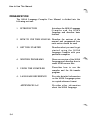
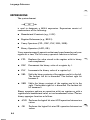
ORGAN IZATION
The 901 0A Language Compiler User Manual is divided into the
following sections:
Introduces the 9010A Language
C o mpiler and the 90 1 OA
Language and describes basic
features.
l.
INTRODUCTION
2.
HOW TO USE THIS MANUAL Describes the sections of the
manual and recommends how
each section should be used.
3.
GETTING STARTED
Describes what you need to get
started us ing the 90 1 OA
Language Compiler with your
particular computer.
4.
WRITING PROGRAMS
Gives an overview of the 90IOA
Language and describes how to
create 901 0A source files.
5.
USING THE COMPILER
D e scribes how to use the
compiler and the file transfer
program.
6.
LANGUAGE REFERENCE
Provides detailed information
on the 90 l OA Language syntax
in a quick-reference format.
APPENDICES A-F
Provides other information
about the 9010A Language.
··�
··�
2-4
How to Use This Manual
SUGGESTED USE
The sections in this manual appear in the order in which they are
intended to be read by a first-time user of the 90 1 0A Language
Compiler. Section 1 , lntroduction, provides an overview of the
features of the 90 1 0A Language Compiler. lf you are a first-time user
of the compiler, the introduction gives you an idea of what to expect.
This section, How to Use this Manual, provides guidance in using the
manual so that you can quickly and correctly begin to use the 90 1 0A
Language Compiler.
Section 3, Getting Started, provides you with the information you need
to get your new compiler running. Before attempting to use the
compiler, it is essential that you read this section thoroughly so that
you can avoid pro blems. Getting S tarted shows yo u how to set up your
host computer system and how to connect it to the 90 1 0A.
Section 4, Writing Programs, uses explanations and examples to
introduce you to the 90 1 OA Language and demonstrates how to create
901 0A program source files. Everyone should read this section at least
once. When yo u become more familiar with the 90 1 OA Language, yo u
will rely less on Section 4 and more on Section 6.
Section 5 , U sing the Compiler, provides information on how to use the
compiler and the file transfer program. This will enable you to create
hex files and transfer them to the 90 1 0A for execution.
S ection 6, Language Reference, con tains much of the same
information as Section 4, but the information is more detailed, and it is
organized to enable quick reference. This section is designed for use
when you are in the middle of a program and need specific syntax
information in a hurry.
A ppendices A through F provide detailed information about the
90 1 0A Language. You will probably use the appendices for quick
reference after you have learned how to use the language.
2-5/2-6
Section 3
Getting Started
CONTENTS
lntroduction . . . . . . . . . . . . . . . . . . . . . . . . . . . . . . . . . . . . . . . .
Fluke 1 720A lnstrument Controller . . . . . . . . . . . . . . . . . . . .
Introduction . . . . . . . . . . . . . . . . . . . . . . . . . . . . . . . . . . . . . .
What Y ou N eed . . . . . . . . . . . . . . . . . . . . . . . . . . . . . . . . . . . .
Backing U p the Program Diskette . . . . . . . . . . . . . . . . . . .
V erifying the W orking Diskette
.....................
Hooking Up the System .
. ..
S ystem Dependencies . . . . . . . . . . . . . . . . . . . . . . . . . . . . . . .
Test Editor . . . . . . . . . . . . . . . . . . . . . . . . . . . . . . . . . . . . .
Disk Space . . . . . . . . . . . . . . . . . . . . . . . . . . . . . . . . . . . . . .
Compiler Organization . . . . . . . . . . . . . . . . . . . . . . . . . . .
Fluke 1 722A lnstrument Controller . . . . . . . . . . . . . . . . . . . .
Introduction . . . . . . . . . . . . . . . . . . . . . . . . . . . . . . . . . . . . . .
What Y o u N eed . . . . . . . . . . . . . . . . . . . . . . . . . . . . . . . . . . .
Backing Up the Program Diskette . . . . . . . . . . . . . . . . . . .
Verifying the W orking Diskette
.....................
Hooking Up the System . . . . . . . . . . . . . . . . . . . . . . . . . . . .
System Dependencies . . . . . . . . . . . . . . . . . . . . . . . . . . . . . . .
Text Editor . . . . . . . . . . . . . . . . . . . . . . . . . . . . . . . . . . . . .
Disk Space . . . . . . . . . . . . . . . . . . . . . . . . . . . . . . . . . . . . .
IBM Personal Computer . . . . . . . . . . . . . . . . . . . . . . . . . . . . . .
Introduction . . -.. . . . . . . . . . . . . . . . . . . . . . . . . . . . . . . .
What You Need
.
. . . ..
..
. .
Backing Up the Program Diskette
.
V erifying the W orking Diskette . . . . . . . . . . . . . . . . . . . . . .
Hooking Up the System
.
..
System Editor
RETURN Key . . . . . . . . . . . . . . . . . . . . . . . . . . . . . . . . . . . .
.
.
.
.
.
.
.
.
.
.
.
.
.
.
.
.
.
.
.
.
.
.
.
.
.
.
.
.
.
.
.
.
.
.
.
.
.
.
.
.
.
.
.
.
.
.
.
.
.
.
.
.
.
.
.
.
.
.
.
.
.
.
.
.
.
.
.
.
.
.
.
.
.
.
.
.
.
.
.
.
.
.
.
.
.
.
.
.
.
.
.
.
.
.
.
.
.
.
.
.
.
.
.
.
.
.
.
.
.
.
.
.
.
.
.
.
.
.
.
.
.
.
.
.
.
.
.
.
.
.
.
.
.
.
.
.
.
.
.
.
.
.
.
.
.
.
.
.
.
.
.
.
.
.
3-3
3-4
3-4
3-4
3-4
3-5
3-6
3-8
3-8
3-8
3-8
3-9
3-9
3-9
3-9
3-1 O
3-10
3-12
3-12
3-12
3-13
3-13
3-1 3
3-14
3-14
3-15
3-16
3-16
3-1
CONTENTS, continued
CP / M Operating Systems
..........
lntroduction . . . . . . . . . . . . . . . . . . . .
What You Need
Backing U p the Program Diskette
V erifying the W orking Diskette . . . .
Hooking Up the System
Installing S oftware
..............
Editor
.........................
.
.
.
.
.
.
.
.
.
.
.
.
.
.
.
.
.
.
.
.
.
.
.
.
.
.
.
.
.
.
.
.
.
.
.
.
.
.
.
.
.
.
.
.
.
.
.
.
.
.
.
.
.
.
.
.
.
.
.
.
.
.
.
.
.
.
.
.
.
.
.
.
.
.
.
.
.
.
.
.
.
.
3-2
.
.
.
.
.
.
.
.
. . . . . . . . . . . . . . . . . . 3-1 7
. . . . . . . . . . . . . . . . . . 3-1 7
3-1 7
3- 1 8
. . . . . . . . . . . . . . . . . . 3-18
3-19
. . . . . . . . . . . . . . . . . . 3-20
. . . . . . . . . . . . . . . . . . 3-20
Getting Started
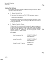
INTRODUCTION
This section provides the information needed to set up your host
computer system to work with the 90 1 0A Language Compiler. For
each version of the compiler, the following information is presented:
•
What You Need
Describes the hardware configuration
required to use the compiler package
•
Backing U p the
Program Diskette
Provides the information needed to create
a working copy of the program diskette
•
Hooking Up the
System
Describes how to connect the 90 1 0A to the
host system and how to set the RS-232-C
serial interface parameters
•
System Dependencies Presents other information that is unique
to a particular host system
Y ou should carefully read the instructions that apply to your host
system. It is not necessary for you to read the material that relates to
other host systems.
3-3
Getting Started
· ·�
FLUKE 1 720A INSTRUMENT CONTROLLER
lntroductlon
The following information applies to the 1 720A version of the 90 l OA
Language Compiler.
What You Need
The following equipment is needed in order to use the compiler
package:
l.
Fluke 9005A or 90 1 0A Micro-System Troubleshooter with
Option 90 1 0A-00 1 , RS-232-C Interface
2.
Fluke 1 720A Instrument Controller (Option 1 720A-00 1 ,
1 28K-Byte E-Disk is recommended.)
3.
Fluke Y 1 705 RS-232-C Null Modem Cable and Y l 7 07 RS232-C Interface Cable
4.
90 1 0A-920 90 1 0A Language Compiler, 1 720A/ 1 722A Version
Backlng Up the Program D iskette
The 90 1 0A Language Compiler package consists of this manual and a
write-protected program diskette containing the compiler itself and
various other programs and data files.
Before using the compiler, you should make a copy of the program
diskette. This copy should be used for normal day-to-day operations,
while the original program diskette should be kept in a safe place as a
backup so that the working copy can be resto red if it is ever damaged.
Complete instructions on how to copy diskettes can be found in the
1 720A File U tility U ser Manual.
3-4
.��
Getting Started
1 720A l nstrument Controller
Verltylng the Worklng D iskette
Once you have created a working copy of the program diskette, yo u
should verify the integrity of its files by running VERIFY, one of the
programs included in the compiler package. To run the VERIFY
program, type
VERIFY <RETURN>
in response to the 1 720A Console Monitor program prompt.
The VERIFY program checks the contents of the 1 720A System
Device (SYO:) to verify the integrity of the Compiler package files. It
calculates a checksum for each of the files and compares it to the
checksum contained in the VERIFY.DAT file. VERIFY.DAT is an
ASCII file that contains a list of filenames and checksums for each of
the files in the compiler package.
Results from the VERIFY program are printed in tabular form as each
file is checked. Missing files or checksum errors (that could indicate
either corrupted files or incorrect version numbers) are reported. If
such problems occur, recopy the diskette and run the VERIFY
program again. If problems persist and you are unable to run any of the
programs, contact a Fluke Technical Service Center.
3-5
Getting Started
1 720A l nstrument Controller
Hooklng Up the System
The 1 720A must be connected to the 90 1 0A whenever you want to
transfer the hex files produced by the compiler to the 90 1 0A for
execution.
l.
U se an RS-232-C interface cable and an RS-232-C null modem
cable to connect the auxiliary interface of the 90 l OA to one of
the serial ports on the 1 720A.
KB 1 : or KB2: can be chosen as the serial port on the 1 720A.
XFER, the file transfer program described in Section 5,
Compiler U sage, allows yo u to specify the port name to be used
when transferring files to the 90 1 0A.
Since XFER defaults to KBI:, it is more convenient to connect
the 90 1 0A to KBI: if KBI: is not already being used for sorne
other purpose.
2.
Set the RS-232-C auxiliary interface parameters on the rear
panel of the 90 1 0A. Suggested settings are:
9600 baud (switch setting 7)
Parity: even
Data bits: 8
Stop bits: 1
Parity: on
90 1 0A Setup parameter NEWLINE must be set to OOOOODOA
(the 90 1 0A default value) for transferring files.
3.
3-6
Set the parameters of the serial port on the 1 720A to
correspond to those of the 90 1 0A. SET, a 1 720A system
program, is included on the program diskette for this purpose.
Refer to the 1 720A Set RS-232-C Utility User Manual for a
complete description of how to use the SET utility.
Getting Started
1 720A 1 nstrument Control ler
NOTE
The STALL option must be enabled on the 1720A ifanyfi/es
are to be transferred from the 90JOA to the 1720A. This option
is not required if files are only transferred from the 1720A to
the 90JOA.
Sorne early versions of the 1720A Set RS-232-C Utility
program do not implement the STALL option. Be sure to use
the Set RS-232-C Utility program that is contained in the
90JOA Language Compiler package.
The End of Line character should be set to JO and the End of
File character shou/d be set to 26 (the 1720A default values).
The following example demonstrates how the SET utility can
be used to select the parameters that corresp ond to the above
90 1 0A settings.
#SET
*KB l : BR 9600 DB 8 PB E SB 1 SI E SO E
*EX
Since the 1 720A serial port parameters must be reestablished
every time the 1 720A is turned on, you will probably want to
incorporate the necessary commands into a system command
file. The 1 720A Floppy Disk Operating System User Manual
contains information on how this is done.
3-7
Getting Started
1 720A l nstru ment Contro l ler
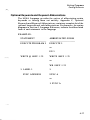
System Dependencles
Text Editor
In order to create and maintain source files on the host system, a
general-purpose text editor is required. The Editor Accessory program
(filename ESX) is the recommended editor for use with the 1 720A.
A copy of the Editor Accessory program is included on the program
diskette, and a copy of the Editor U ser Manual is included with the
compiler package.
Disk Space
After using the Editor or Compiler programs, it may be advantageous
to pack the disk contents, using the 1 P option in the 1 720A File U tility
program, to provide as much free disk space as possible. Refer to the
1 720A File Utility U ser Manual if you need help with packing the disk.
The message
?Readj write past physical end of file
means that there was not enough contiguous disk space to create the
output files. Delete any unnecessary files, pack the disk, and try again.
Compilar Organization
The Compiler program is constructed of overlayed program segments,
sorne of which must be loaded during program execution. Therefore, if
the Compiler program is being used from a floppy disk, the disk must
remain in the disk drive while the program is running. Do not remove
the disk until the program is finished.
If the overlays are not available when needed, the fatal error message
!Unable to load overlay
will be displayed.
3-8
Getting Started
FLUKE 1 722A I NSTR UMENT CONTROLLER
1 ntroductlon
The following information applies to the 1 722A version of the 90 1 0A
Language Compiler.
What You Need
The following equipment is needed in order to use the compiler
package:
l.
Fluke 9005A or 90IOA Micro-System Troubleshooter with
Option 90 1 OA-00 1 , RS-232-C Interface.
2.
Fluke 1 722A I nstrument Controller.
3.
Fluke Y 1 705 RS-232-C Null Modem Cable and Y 1 707 RS232-C Interface Cable.
4.
Fluke 90 1 0A-920 90IOA Language Compiler, 1 720A j 1 722A
Version.
Backlng Up the Prog ram Diskette
The 90 1 OA Language Compiler package consists of this manual and a
write-protected program diskette containing the compiler itself and
various other programs and data files.
Before using the compiler, you should make a copy of the program
diskette. This copy should be used for normal day-to-day operations,
while the original program d iskette should be kept in a safe place as a
backup so that the working copy can be resto red if it is ever damaged.
Complete instructions on how to copy diskettes can be found in the
1 722A System Manual.
3-9
Getti n g Started
1722A l nstrument Control ler
Verlfylng the Worklng Diskette
Once you have created a working copy of the program diskette, you
should verify the integrity of its files by running VERIFY, one of the
programs included in the compiler package. To run the VERIFY
program, type
VERIFY <RETURN>
in response to the 1 722A FDOS prompt.
The VERIFY program checks the contents of the 1 722A System
Device (SYO:) to verify the integrity of the compiler package files. 1t
calculates a checksum for each of the files and compares it to the
checksum contained in the VERIFY. DAT file. VERIFY . DAT is an
ASCII file that contains a list of filenames and checksums for each of
the files in the compiler package.
Results from the VERIFY program are printed in tabular form as each
file is checked. Missing files or checksum errors (that could indicate
either corrupted files or incorrect version numbers) are reported. If
such problems occur, recopy the diskette and run the VERIFY
program again. If problems persist and yo u are unable to run any of the
programs, contact a Fluke Technical Service Center.
Hooklng Up the System
The 1 722A must be connected to the 90 10A whenever you want to
transfer the hex files produced by the compiler to the 90 1 0A for
execution.
l.
U se an RS-232-C interface cable and an RS-232-C null modem
cable to connect the auxiliary interface of the 90 1 OA to the
serial port on the 1 722A.
2.
Set the RS-232-C auxiliary interface parameters o n the rear
panel of the 901 0A. Suggested settings are:
9600 baud (switch setting 7)
Parity: even
Data bits: 8
Stop bits: 1
Parity: on
3-1 0
-
Getting Started
1722A l nstru ment Controller
The 901 0A Setup parameter NEWLINE must be set to
OOOOODOA (the 9010A default value) for transferring files.
3.
Set the parameters of the serial port on the 1 722A to
correspond to those of the 90 10A. The Set Utility program
(SET), a 1 722A system program, is included on the program
diskette for this purpose. Refer to the 1 722A System Manual
for a complete description of how to use the SET utility.
NOTE
The STALL option must be enabled on the 1722A ifanyfiles
are to be transferred from the 9010A to the 1722A. This option
is not required iffiles are on/y transferred from the 1722A to
the 9010A.
The End of Line character should be set to JO and the End of
File character should be set to 26 (the 1722A default values).
The following example demonstrates how the SET utility can
be used to select the parameters that correspond to the above
90 1 0A settings.
#SET
*KB l : BR 9600 DB 8 PB E S B 1 SI E SO E
*EX
Since the 1 722A serial port parameters must be reestablished
every time the 1 722A is turned on, you will probably want to
incorporate the necessary commands into a system command
file. The 1 722A System Manual contains information on how
this is done.
3-1 1
Getti n g Started
1 722A l nstrument Control ler
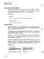
System Dependencles
Text Editor
In order to create and maintain source files on the host system, a
general-purpose text editor is required. The Editor Accessory program
(filename E DIT) is the recommended editor for use with the 1 722A.
A copy of the Editor Accessory program is included on the program
diskette, and instructions for using the editor are included as an
Addendum to this manual.
Disk Space
After using the Editor or Compiler programs, it may be advantageous
to pack the disk contents, using the 1 P option in the 1 722A File Utility
program, to provide as much free disk space as possible. Refer to the
1 722A System Manual if you need help with packing the disk.
The message
?Read 1 write past physical end of file
means that there was not enough contiguous disk space to create the
output files. Delete any unnecessary files, pack the disk, and try again.
3-1 2
Getti n g Started
IBM PERSONAL COMPUTER
l ntroductlon
The following information applies to the IBM Personal Computer
(PC) version of the 90 10A Language Compiler.
What You Need
The following equipment is needed in order to use the compiler
package:
l.
9005A or 90 1 0A Micro-System Troubleshooter with Option
90 1 0A�O l RS-232 Interface.
2.
I B M Personal Computer (model PC o r XT) with:
a.
A monochrome or color display.
b. Version 1 . 1 or 2.0 of the IBM DOS Operating System.
c.
At least 1 28 K bytes of RAM.
d . A disk drive. W e recommend using two disk drives o r a
fixed Winchester technology disk drive.
e.
An RS-232-C interface.
3.
Fluke Y 1 705 RS-232-C Null Modero Cable and Fluke Y l 707
RS-232-C Interface Cable.
4.
Fluke 90 1 0A-923 90 1 0A Language Compiler (IBM PC
version).
3-1 3
Getti n g Started
I B M Personal Com putar
Backing Up the Program Diskette
The 90 1 OA Language Compiler package consists of this manual and a
write-protected program diskette containing the compiler itself and
various other programs and data files.
Before using the compiler, you should make a copy of the write
protected program diskette. This copy is used for normal day-to-day
operations, while the original program diskette should be kept in a safe
place as a backup so that the working copy can be resto red if it is ever
damaged.
Complete instructions on how to copy diskettes can be found in the
IBM Disk Operating System (DOS) User Manual.
Verifying the Working D iskette
Once you have created a working copy of the program diskette, you
should verify the integrity of its files by running VERIFY, one of the
programs included in the compiler package. To run the VERIFY
program, put the working diskette in drive a: and then type
a:VERIFY <RETURN>
in response to the I B M system prompt.
The VERIFY program checks the contents of the copy to verify the
integrity of the compiler package files. lt calculates a checksum for
each of the files and compares it to the checksum contained in the
VERIFY.DAT file. VERIFY.DAT is an ASCII file that contains a list
of filenames and checksums for each of the files in the compiler
package.
Results from the VERIFY program are printed in tabular form as each
file is checked. M issing files or checksum errors (that could indicate
either corrupted files or incorrect version numbers) are reported. lf
such problems occur, recopy the diskette and run the VERIFY
program again. If problems persist and you are unable to run any of the
programs, contact a Fluke Technical Service Center.
3-1 4
Getting Started
I B M Personal Computer
Hooklng Up the System
The IBM PC must be connected to the 90 10A whenever you want to
transfer the hex files produced by the compiler to the 90 l OA for
execution.
l.
U se an RS-232 interface cable and an RS-232 null modem
cable to connect the auxiliary interface of the 90 1 OA to a serial
port on the IBM PC.
2.
Set the RS-232 auxiliary interface parameters on the rear panel
of the 90 l OA. S uggested settings are:
2400 baud (switch setting 5)
Parity: On
Data bits: 8
Stop bits: 1
Parity: Even
3.
Set the parameters of the serial port on the IBM PC to
correspond to those of the 90 1 0A.
You may use the IBM MODE command to configure the serial
port.
Refer to the IBM instruction manuals for help.
4.
The NEWLINE setup parameter should be set to IOOOODOA
for transferring files. lf transmission errors occur, it may be
necessary to change the timing delay to a larger value. See the
90 1 0A Operator Manual for more information.
5. The 90 10A setup parameters STALL and UNSTALL should
be set to 1 3 and 1 1 respectively (the 90 l OA default values) when
transferring files.
3-1 5
Getti n g Started
IBM Personal Computer
System Editor
In order to create and maintain source files on the host system, a
general-purpose text editor is required. Any general-purpose editor
may be used with 901 0 A language source files.
RETURN Key
References to the RETURN key in this manual refers to the
key on the IBM Personal Computers.
3-1 6
Gett i n g Started
CP/M OPERATING SYSTEMS
l ntroductlon
The following information applies to the version of the 90 1 0A
Language Compiler for CP j M systems.
CP j M (Control Program for Microcomputers) is a product of Digital
Research, Inc. lt is a general-purpose operating system that runs on a
wide variety of host computers.
What You Need
The following equipment is needed in order to use the compiler
package with a host computer running the CP j M operating system:
l.
9005A or 90 10A Micro-System Troubleshooter with Option
901 0A-00 1 RS-232 Interface
2.
CP / M compatible Z80 based host computer system with:
a.
At least one eight-inch IBM 3740 format disk drive. We
recommend using two disk drives.
b. Standard CP 1 M Operating System software (version 2.2).
c.
An RS-232-C interface.
3.
An RS-232-C Interface Cable suitable for connecting your
host computer system to the 90 1 0A . For example, use a Fluke
Y 1 709 RS-232-C Interface Cable to connect a Kaypro I I
Personal Computer t o a 90 1 0A.
4.
Fluke 90 1 0A-92 1 , the version of the 90 1 0A Language
Compiler package for CP j M on eight inch disks, or 90 1 OA922, the version for the Kaypro 11 Personal Computer with
CP j M on a 5-1 j4 inch disk.
3-1 7
Getting Started
CP/M Operating Systems
Backing Up the Program D iskette
The 90 1 OA Language Com piler package consists of this manual and a
write-protected program diskette containing the compiler itself and
various other programs and data files.
Befare using the compiler, you should make a copy of the write
protected program diskette. This copy is used for normal day-to-day
operations, while the original program diskette should be kept in a safe
place as a backup so that the working copy can be resto red if it is ever
damaged.
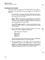
Verlfylng the Worklng Diskette
Once you have created a working copy of the program diskette, you
should verify the integrity of its files by running VERIFY, one of the
programs included in the compiler package. To run the VERIFY
program, type
<VERIFY R ETURN >
in response to the CP / M system prompt.
The VERIFY program checks the contents of the copy to verify the
integrity of the compiler package files. It calculates a checksum for
each of the files and compares it to the checksum contained in the
VERIFY.DAT file. VERIFY.DAT is an ASCII file that contains a list
of filenames and checksums for each of the files in the compiler
package.
Results from the VERIFY program are printed in tabular form as each
file is checked. M issing files or checksum errors (that could indicate
either corrupted files or incorrect version numbers) are reported. If
such problems occur, recopy the diskette and run the VERIFY
program again. If problems persist and you are unable to run any of the
programs, contact a Fluke Technical Service Center.
3-1 8
Getting Started
CP/M O perating Systems
Hooking U p the System
The host computer must be connected to the 901 0 A whenever you
want to transfer the hex files produced by the compiler to the 90 l OA for
execution.
l.
Use an RS-232 interface cable to connect the auxiliary
interface of the 90 l OA to a serial port on the host computer.
2.
Set the RS-232 auxiliary interface parameters on the rear panel
of the 90 1 0A. Suggested settings are:
9600 baud (switch setting 7)
Parity: Even
Data bits: 8
Stop bits: 1
Parity: on
3.
The NEWLINE setup parameter should be set to 1 0000DOA
for transferring files. If transmission errors occur, it may be
necessary to change the timing delay to a larger value. See the
90 1 0A Operator Manual for more information.
4.
The 90 1 0A setup parameters STALL and UNSTALL should
be set to 1 3 and 1 1 respectively (the 90 1 0A defaull values) when
transferring files.
5.
Set the parameters of the serial port on the host computer to
correspond to those of the 90 1 O A.
Refer to I nstalling Software in this section for further
information on setting the RS-232 parameters.
--�
3-1 9
Getting Started
CP/M O perating Systems
l nstalllng Software
On CP j M systems, the File Transfer utility program (XFER) uses
information from a data file for configuring RS-232-C transfers. This
file, CONFIG.PRT, is automatically created for each system the first
time that the File Transfer program is used.
The program will prompt for information about RS-232-C port
parameters, and use the information that you enter to create the data
file on the system default disk.
·
Refer to the host computer's instruction manuals if you need further
information to answer the prompts.
Once the CONFIG.PRT data file is available on the disk, it will
automatically be used for subsequent file transfers with the XFER
program. This file contains port status and data addresses, an optional
baud rate address, and SIO initialization bytes.
To change the RS-232-C configuration in the CONFIG.PRT file, use
the Configure option (C) in the File Transfer program. The prompts
will be repeated to allow you to redefine the configuration.
Note that the CONFIG.PRT file will be created on the system default
device. The system disk must not be write-protected at this time.
Editor
In order to create and maintain source files on the host system, a
general-purpose text editor is required. Any general-purpose editor
may be used with 90 1 0A Language source files.
3-20
Section 4
Writing Programs
CONTENTS
I ntroduction . . . . . . . . . . . . . . . . . . . . . . . . . . . . . . . . . . . . . . . . .
Part 1 : General Program Format . . . . . . . . . . . . . . . . . . . . . . .
Introduction . . . . . . . . . . . . . . . . . . . . . . . . . . . . . . . . . . . . . . .
Important Details . . . . . . . . . . . . . . . . . . . . . . . . . . . . . . . . . .
Program Comments . . . . . . . . . . . . . . . . . . . . . . . . . . . . . . . .
90 1 0A Programs . . . . . . . . . . . . . . . . . . . . . . . . . . . . . . . . . . .
Address Space Information . . . . . . . . . . . . . . . . . . . . . . . . . .
Setup Information . . . . . . . . . . . . . . . . . . . . . . . . . . . . . . . . . .
Pod Data Files . . . . . . . . . . . . . . . . . . . . . . . . . . . . . . . . . . . . .
90 1 0A/ Pod Interaction . . . . . . . . . . . . . . . . . . . . . . . . . . . . . .
Sample Program . . . . . . . . . . . . . . . . . . . . . . . . . . . . . . . . . . .
Part 2: Coding Shortcuts . . . . . . . . . . . . . . . . . . . . . . . . . . . . . .
Introduction
Optional Keywords and Keyword Abbreviations . . . . . . . .
Unary Operator Shorthand . . . . . . . . . . . . . . . . . . . . . . . . . .
Default Entries . . . . . . . . . . . . . . . . . . . . . . . . . . . . . . . . . . . . .
File Inclusion . . . . . . . . . . . . . . . . . . . . . . . . . . . . . . . . . . . . . .
Sample Program . . . . . . . . . . . . . . . . . . . . . . . . . . . . . . . . . . .
Part 3: Symbolic Names . . . . . . . . . . . . . . . . . . . . . . . . . . . . . . .
Introduction . . . . . . . . . . . . . . . . . . . . . . . . . . . . . . . . . . . . . . .
Symbolic Program Names . . . . . . . . . . . . . . . . . . . . . . . . . . .
Symbolic Labels . . . . . . . . . . . . . . . . . . . . . . . . . . . . . . . . . . . .
Symbolic Register Names . . . . . . . . . . . . . . . . . . . . . . . . . . . .
Predefined Register N ames . . . . . . . . . . . . . . . . . . . . . . . . . .
Sample Program . . . . . . . . . . . . . . . . . . . . . . . . . . . . . . . . . . .
.
.
.
.
.
.
.
.
.
.
.
.
.
.
.
.
.
.
.
.
.
.
.
.
.
.
.
.
.
.
.
.
.
.
.
.
.
.
.
4-3
4-4
4-4
4-5
4-7
4-8
4-8
4-9
4-1 1
4-1 2
4-1 3
4-1 6
4-1 6
4-1 7
4-1 8
4-1 8
4-1 9
4-20
4-22
4-22
4-24
4-26
4-28
4-29
4-30
4-1 /4-2
Writing Programs
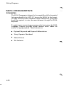
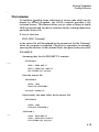
I NTRODUCTION
This section provides the information you need to write programs for
the 90 1 OA Language Compiler. The section is divided into three parts.
Each part is self-contained and describes increasingly more advanced
features of the 90 1 OA Language.
The three parts cover the following tapies:
PART 1 : GENERAL PROGRAM
FOR M AT
Describes how to write simple
programs using the standard
fe a t u r e s o f t h e 9 0 1 0 A
Language
PART 2: CODING S HORTC UTS
I n troduces sorne extended
fe a t u r e s o f t h e 9 0 1 0 A
Language which reduce the
amount of typing required to
enter programs
PAR T 3: SYMBOLIC NAM E
Allows programs to be made
more readable and easier to
maintain by using mnemonic
names for programs, labels,
and registers
The best way to learn the 90 1 0A Language is to start by reading
through Part 1 of this section, and then skip directly to Section 5, U sing
the Compiler. You should use the compiler to compile the example
programs provided in Part 1 , and then try writing sorne simple
programs of your own.
Once you feel comfortable with the concepts covered in Part 1 , you can
return at any time to this section and proceed with the more advanced
concepts covered in the remaining parts . The compiler can be used
productively at any of the three levels.
4-3
W riti n g Programs
PART 1 : GEN ERAL PROGRAM FORMAT
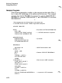
lntroductlon
The 90 1 OA Language Compiler allows you to create source files
identical to those that the 90 1 0A AUX I / F functions send via the RS232-C auxiliary interface. These files can contain the entire contents of
the 901 0A memory - not only 90 1 0A programs but also any available
address space and setup information.
In source files for the 90 1 0A Language Compiler, address space
information, setup information, and programs are described in
separate blocks. These blocks are identified with compiler keywords,
such as SETUP INFORMATION. This section provides information
about using the various blocks and shows sorne sample source files.
In the 90 1 OA language, program statements use an expanded syntax to
take advantage of the flexibility of the host system text editor and to
provide enhanced readability. Program lines may contain comments
and symbolic names. More information about source files and
program lines is found throughout this section. Section 6, Language
Reference, contains detailed information on the syntax and usage of
each 90 1 OA program statement.
The following is an example of a short source file containing two valid
901 0A programs and no address space or setup information:
PROGRAM O
DPY- THIS /S A N EXA MPLE
EXECUTE PROGRAM 1 0
DPY-OF A VALlO 9010A PROGRAM
PROGRAM 10
REG 1 = 40
0: LABEL O
DEC REG 1
IF REG1 > O G O TO O
4-4
Writi n g Prog rams
General Program Format
lmportant Detalla
When writing programs for the 90 1 0A Language Compiler on your
computer, you will find that it is necessary to pay attention to sorne
details that you could ignore when entering programs using the 90 1 0A
keyboard. These important rules are:
•
Each 90 1 OA statement must be on a separate line. Continuation
lines are not allowed.
•
A statement may begin in any column.
•
Spaces and tabs are ignored, except when they occur in DPY or
AUX statements.
•
Blank lines are ignored.
•
Adjacent keywords, symbolic names (described in Part 3 of this
section), and numbers must be separated by at least one space.
EXAMPLES:
•
VALID
INVALID
READ PROBE
READPROBE
DTOG @ 1 00F9 = 80 BIT 7
DTOG @ 1 00F9 = 80 BIT7
Uppercase and lowercase characters can be used interchangeably.
EXAMPLE:
The following program statements are all equivalent:
WRITE @ 1 00FA = 1
write @ 1 OOfa = 1
Write @ 1 00FA = 1
4-5
W riting Programs
General Program Format
•
In a few cases, the 90 1 OA Language does not correspond exactly to
the keys that would be pressed if the program were being entered
on the 90 1 0A keyboard.
For example, INC REG5 is a legal statement accepted by the
compiler. However, the keystrokes used to create this statement on
the 90 1 0A are INC 5, which would not be accepted by the compiler.
As another example, REGA = REGA INC is a legal statement
accepted by the compiler, but the keystrokes used to create this
statement on the 90 1 0A are REG A INC, which would not be
accepted.
•
In general, the keywords of the 90 1 OA Language are not identical
to the wording that appears on the 90 1 0A keyboard.
For example:
KEYBOAR D
90 1 0A LANGUAGE
DISPL
DPY
COMPL
CPL
RPEAT
REPT
TOGGL DATA
DTOG
In all cases, however, the keywords accepted by the compiler are
compatible with listings produced by the 90 1 0A through the RS232-C auxiliary interface.
4-6
A�
Writing Prog rams
General Program Format
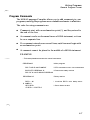
Program Comments
The 90 1 0A Language Compiler allows you to add comments to your
programs, making the programs more readable and easier to maintain.
The rules for using comments are:
•
Comments start with an exclamation point ( !), and they extend to
the end of the line.
•
A comment can be on the same line as a 901 OA statement, or it can
be on a separate line.
•
If a comment extends over several lines, each line must begin with
an exclamation point .
•
A comment cannot be placed in the middle of a 90 1 0A statement.
EXAMPLE:
! This example demonstrates the use of comments.
PROGRA M O
! Main program
DPY- THIS /S A N EXAMPLE
! D P Y s t a t e m e n ts c a n h a ve comments
EXECUTE PROGRAM 10
! Execute the de/ay routine
DPY-OF A VA LlO 9010A PROGRAM
PROGRAM 10
REG 1
=
40
! De/ay routine
! l n i tialize R E G 1
with de/ay count
0: LABEL O
DEC REG 1
! Count down to zero
IF REG 1 > O G O TO O
4-7
W riti ng Programs
General Program Format
901 0A Programs
The 90 1 0A Language allows programs to be specified in the same form
that would be produced by the 90 1 0A AUX 1 / F PROGM keys. By
connecting a printer to the auxiliary interface of the 90 1 0A, you can
obtain formatted listings of your 90 1 OA programs. These listings can
serve as examples of acceptable syntax.
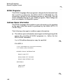
Address Space l nformation
The 90 l OA Language allows address space information to be specified
in the same form that would be produced by the 90 1 0A AUX 1 / F
LEARN keys.
The following rules apply to address space information:
•
The address space information must appear at the beginning of the
so urce file, preceding all 90 l OA programs (i.e. , befo re the first
PROG RAM statement).
U p to lOO add ress descriptors may be specified.
EXAMPLE:
! This is a n example o f a source file con taining
! U U T memory map inform a tion
A DDRESS SPACE INFORMA TI ON
RAM @ COOO-FFFF
ROM @ 0000- 1 FFF SIG 0295
ROM @ 2000-3FFF S I G C262
PRO G RA M O
RAM S H O R T
ROM TES T
··�
4-8
Writing Prog rams
General Program Format
Setup l nformatlon
The 90 1 0A Language allows any or all of the setup parameters to be
specified in the same form produced by the 90 10A AUX 1 / F SETUP
keys.
The 90 1 0A setup functions allow the operator to control the reporting
of UUT errors, enable microprocessor lines, and specify operating
parameters. The 90 1 0A Operator M anual contains complete
information on the various setup parameters that can be specified.
The following rules apply to setup information:
•
Setup information must appear at the beginning of the source file,
preceding all 90 1 0A programs (i.e., before the first PROGRAM
statement). The setup information may appear either before or
after any address space information.
•
You can specify all of the setup parameters, sorne of them, or non e
of them. Setup parameters that are not explicitly set assume default
values contained in the pod data file (if a pod data file is specified),
or to the power-up values supplied by the 90 1 0A.
•
Sorne setup information is pod-dependent. The pod-unique
information includes enableable forcing lines, the default bus test
address, and the RUN UUT address. If any of your 90 10A
programs depend u pon the pod-unique features (i.e., a forcing line
needs to be disabled or a RUN U UT must be performed at the
pod's default address, then the appropriate Pod Data file needs to
be included in the source file. To do this, an INCLUDE statement
is used to specify the correct Pod Data file:
INCLUDE "podname.POD"
This statement must appear befare the setup information in the
source file.
EXAMPLE:
INCLUDE "8086.POD"
4-9
Writing Programs
General Program Format
The INCLUDE statement is described in Part 2 of this section. Pod
data files are described below.
•
A POD statement should be placed in the setup section ifany ofthe
programs depend upon pod-unique features.
EXAMPLE:
INCLUDE "8086. POD"
SETUP INFORMA TION
POD - 8086
TRAP A C TIVE FORCE LINE/NO
TRAP A C TIVE INTERRUPT- YES
4-1 0
Writing Programs
General Program Format
Pod Data Files
The 90 1 OA Language Compiler program diskette contains a collection
of files with names like 8086.POD, 68000.POD, etc. These files contain
pod-specific definitions for enableable forcing lines, bus test address
(BUSAD R), and RUN UUT address (UUTADR). If you want to
specify any of the pod-specific setup parameters, you should merge the
appropriate pod data file into your source file by using an INCLU DE
statement. The INCLUDE statement must appear befare the SETUP
INFORMATION section.
Pod-specific forcing lines are defined in the pod data file. The pods
equate each of the forcing lines to a bit in an enable mask.
For example, the definitions for an 8086 pod are shown below:
! Each of the enableab/e forcing lines must be defined as the
! appropriate bit in the enable mask.
FORCELN REA D Y = O
! REA D Y is bit O in the enab/e mask
FORCELN HOLD = 1
! HOLD is bit 1 in the enab/e mask
FORCELN INTR = 3
! INTR is bit 3 in the enable mask
BUSADR
! BUSADR is the pod's default BUS TES T
�
0000
address
UUTADR = FFFFO
! UUTADR is the pod's default RUN UUT
address
! Other definitions can follow
4-1 1
W riti n g Programs
General Program Format
901 0A/Pod lnteraction
Setup information takes effect immediately upon loading a new hex
file into the 90 1 0A (whether through READ TAPE or AUX 1/ F
READ). An interaction takes place between the 90 1 0A and the
interface pod when the hex file is loaded and setup information may be
changed to the default setting of the pod if:
l.
The pod name was not specified with a POD statement in the
setup section, or
2.
A different pod is connected to the 90 1 0A while the hex file is
being loaded into the 90 1 0A .
T o avoid changing the parameters i n pod-dependent programs:
l.
An INCLUDE statement must be used in the setup section of
the s o urce program to include information from the
appropriate Pod Data file.
2.
A POD statement must be used in the setup section of the
source program to identify which pod is being used.
3.
The correct pod (or no pod) must be connected to the 90 1 0A
when downloading a compiled hex file.
."""""'
·�.
4-1 2
Writing Programs
General Program Format
Sample Program
The following sample source file illustrates the concepts introduced in
Part l . This example can be u sed as a basis for writing your own 90 l OA
programs. Befare continuing to Part 2, you may wish to copy this
program using your host computer and transfer it to your 90 1 OA as an
exercise.
Section 5, Using the Compiler, shows how to run the compiler and
transfer the generated hex files to the 90 1 0A.
Once you feel comfortable using the compiler at this level, you should
proceed with Part 2, which introduces sorne extended features that
simplify the task of writing larger test programs.
! Th is program tests the U52 flip-flop on the output side
! of the B255 PIA on the NEC TK-BOA single-board computer.
INCLUDE "BOBO. POD"
SETUP INFORMA TI ON
POD - BOBO
TRAP A C TI VE FORCE LINE-NO
TRAP A C TIVE IN TERRUPT- YES
A DDRESS SPACE INFORMA TION
! Note: this address space information
RAM @ BCOO-BFFF
! is not ac tual/y used by the
ROM @ 0000-07FF SIG F77C
! program, but the descriptors
1!0 @ 100FB-100FA BITS FF
! wi/1 be loaded into the 9010A
PROGRAM O
WRITE @ 1 00FB = BO
0: LABEL O
! Main program
! Configure PIA for output
! Set up en try
REG2 = A
! Set up 10 stimulus loops
REGB = 1A09
! Store U52 - pin9 for prompt
EXECUTE PROGRAM 3
! Prompt for probe placement
EXECUTE PROGRAM 1
! Detect probe placement
IF REGB = 1 G O TO 1
! Branch on open node
DPY- TES TING U52#
! Display - Testing U52
READ PROBE
! Clear probe data register
4-1 3
Writi n g Programs
General P rogram Format
2: LABEL 2
! Stimu/us loop
WR/TE @ 1 00FA = 1
! Se t f/ip flop D input high
D TO G @ 1 00F9 = 80 BIT 7
! Toggle flip flop
WRITE @ 1 00FA = O
! Set f/ip flop D input low
D TOG @ 1 00F9
! Toggle again
=
80 BIT 7
DEC REG2
IF REG2 > O G O TO 2
! Loop for 10 tries
EXECUTE PROGRAM 2
! Extract probe data
IF REG8 = A G O TO 3
! Branch on probe count = 1 0
DPY-U52 TO G G L ING IMPROPERL Y#
! Display bad toggle
G O T0 4
! Exit
1: LABEL 1
! Open node loop
DPY-WA S PROBE IN PLACE# ?1
! Query
IF REG1 = O G O TO O
! Branch if probe not ready
DPY-U52 OPEN#
! Display - U52 bad
G O T0 4
! Exit
3: LABEL 3
! Device passed
DPY-U52 TES T PASSED#
4: LABEL 4
! End
PROGRAM 1
! Program to detect probe placement
SYNC FREE-RUN
0: LABEL O
! Open count
REG2 = 20
! Debounce count =20
1: LABEL 1
=
50
! Open loop
READ PROBE
! Gather leve/ information
IF REGO ANO 5000000 > O G O TO 2
! Branch on bounce leve/
DEC REG 1
! Decrement open count
IF REG 1 > O G O TO 1
! Loop if count > O
REG8 = 1
! Set Open Node flag
G O T0 3
! Exit
2: LABEL 2
! Debounce loop
DEC REG2
! Decrement debounce count
READ PROBE
! Gather leve/ information again
IF REGO ANO 5000000 = O G O TO O
! Branch on open leve/
IF REG2 > O G O TO 2
! Loop if count > O
REG8 = O
3: LABEL 3
4-1 4
! Set counts
REG 1 = 50
! Set Begin Test flag
! End
Writing Programs
General Program Format
PROGRAM 2
! Program to extract the probe data
REAO PROBE
! Gather probe information
REGB = REGO A NO 7F
! Extract count
REG9 = REGO SHR SHR SHR SHR SHR SHR SHR SHR ANO FFFF ! Extract Sig.
REGA
=
REGO SHR SHR SHR SHR SHR SHR SHR SHR
REGA
=
REGA SHR SHR SHR SHR SHR SHR SHR SHR
REGA = REGA SHR SHR SHR SHR SHR SHR SHR SHR ANO 7 ! Extract leve/
PROGRAM 3
REG2 = REGB ANO 7F
! Program to prompt the operator
! Register 2
=
pin number
REG 1 = REGB SHR SHR SHR SHR SHR SHR SHR ANO 7F ! R1
OPY-PROBE U@ 1 PIN @2#
=
Oevice num.
! Prompt for probe placement
4-1 5
W riting Programs
PART 2: COD ING SHORTCUTS
lntroductlon
The 901 0A Language is designed to be compatible with the formatted
listings produced by the AUX 1 / F keys on the 90 1 0A. In this format,
you may find that sorne statements require much more typing than
would be required to enter the same statement through the 90 l OA
keyboard.
To make it easier to enter large programs on the host system, the 90 l OA
Language Compiler provides several features which reduce the
amount of typing required. These features are:
4-1 6
•
Optional Keywords and Keyword Abbreviations
•
Unary Operator Shorthand
•
Default Entries
•
File lnclusion
Writing Prog rams
Codi n g Shortcuts
Optional Keywords and Keyword Abbreviatlons
The 90 1 0A Language provides the option of abbreviating certain
keywords or leaving them out entirely. Appendix C, Optional
Keywords and Keyword Abbreviations, contains a complete list of the
optional keywords and valid abbreviations. Furthermore, the syntax
diagrams in Section 6, Language Reference, indicate the abbreviated
forro of each statement in the language.
EXAMPLES:
STATEMENT
ABBREVIA TED FOR M
EXECUTE P ROGRAM 5
EXECUTE 5
or
EX 5
W R ITE @ l OOFF = 25
W R ITE l OOFF = 25
or
WR l OOFF = 25
3: LABEL 3
SYNC ADDRESS
3:
SYNC A
or
3: SYNC A
4-1 7
Writi n g Programs
Codi n g Shortcuts
U nary Operator Shorthand
For multiple applications of a unary operator (INC, DEC, CPL, S HL,
or S H R), you may specify the unary operator followed by a decimal
number indicating how many times it is to be applied.
EXAMPLE:
statement
REG 1 = REGO SHR SHR SHR SHR SHR SHR SHR ANO 7F
be abbreviated to
REG 1 = REGO SHR 7 ANO 7F
Default Entrles
When programs are created through the 90 l OA keyboard, many of the
en tries in a program step can be defaulted to the appropriate dedicated
register by pressing the ENTER key.
For example, to create the statement READ @ R EGF, you need only
press the R EAD and ENTER keys on the 90 1 0A. The read address
automatically defaults to R EGF.
Similarly, if the WRITE and ENTER keys are pressed on the 90 1 0A,
the write address automatically defaults to R EGF, and the data to be
written defaults to REGE.
The 90 l OA Language provides a similar default capability. Y ou can
use an asterisk (*) to indicate that an entry should default to a
dedicated register. The syntax diagrams in Section 6, Language
Reference, indicate which entries can be defaulted in this way.
EXAMPLES:
4-1 8
STATEMENT
DEFAULT FOR M
READ REGF
READ *
WRITE REGF = REGE
WRITE * = *
A"""'
Writi n g Prog rams
Coding Shortcuts
File l ncluslon
To facilitate handling large collections of source code which can be
shared by severa! programs, the 90 l O A compiler provides a file
inclusion feature. This feature allows you to crea te a library of useful
90 1 OA programs and use the file inclusion facility to merge them into a
particular source file.
A line of the form
INCLUDE "filename"
in the source file will be replaced by the contents of the file "filename"
when the program is compiled. The effect is equivalent to manually
entering the contents of the included file at that point in the source file.
EXAMPLE:
Assuming that the file PROMPT.S contains
PROGRA M 3
REG2
=
REGB ANO 7F
REG 1
=
REGB SHR 7 ANO 7F
OPY-PROBE U@ 1 PIN @2#
then the source file
PROGRA M O
REGB
=
1A09
EXECU TE PROGRAM 3
JNCLUOE "PROMP T. S "
have exactly the same effect as the source file
PROGRA M O
REGB
=
1A09
EXECUTE PROGRA M 3
PROGRAM 3
REG2
=
REGB ANO 7F
REG 1
=
REGB SHR 7 A NO 7F
OPY-PROBE U@1 PIN @2#
4-1 9
Writing Prog rams
Codi n g S hortcuts
Sample Prog ram
The following example is similar to the one given at the end of Part 1 ,
but it takes full advantage of the abbreviation features. The example
assumes that the file P ROBE l .S contains the code for P ROGRAM 1 ,
PROBE2 . S contains P RO G R A M 2 , and P R O M P T . S contains
PROGRAM 3 .
! This program tests the U52 flip-flop o n the output side
! of the 8255 PIA on the NEC TK-80A single-board computer.
INCLUDE "8080. POD"
SETUP
! Equivalent to SETUP INFORMA TION
POD - 8080
TRAP A C TI VE FORCE LINE NO
! - in SETUP statements is optional
TRA P A C TIVE INTERRUPT YES
A DDRESS SPA CE
RAM 8C00-8FFF
! @ omitted
ROM 0000-07FF SIG F77C
1/0 100F8- 100FA B I TS FF
PROGRAM O
WR 100FB
=
80
! WRITE abbreviated to WR
0: REG2 = A
REG8
=
1A09
OEX 3
! Same as EXECUTE PROGRAM 3
EX 1
IF REG8 = 1 G O TO 1
DPY TES TING U52#
PROBE
2: WR 1 00FA = 1
! Short form of LABEL statement
DTOG 1 00F9 = 80 BIT 7
WR 100FA = O
D TOG 100F9 = 80 B I T 7
DEC REG2
IF REG2 > O G O TO 2
EX 2
IF REG8 = A G O TO 3
DPY U52 TO GGL/NG IMPROPERL Y#
G O T0 4
4-20
! - is optional in DPY statement
Writing Prog rams
Codi n g Shortcuts
1: DPY WAS PROBE IN PLA CE# ?1
IF REG1 = O G O TO O
DPY U52 OPEN#
G O T0 4
3: DPY U52 TES T PASSED#
4:
INCLUDE "PROBE1 . S "
! Coda for PROGRAM 1 is insertad he re
INCLUDE "PROBE2. S"
! PROGRAM 2
INCLUDE "PROMPT. S "
! PROGRAM 3
4-21
Writing P rog rams
PART 3: SYMBOLIC NAMES
l ntroductlon
The 90 1 0A Language allows programs, labels, and registers to be
referred to by symbolic names. For example, the statement
EXECUTE P ROGRAM 5
could be replaced by something more meaningful, such as
EXECUTE P ROGRAM DELA Y
Symbolic names can contribute greatly to the readability of programs,
allowing the programs to be self-documenting to a large degree.
The following rules apply to symbolic names:
4-22
•
Symbolic names must begin with a letter, and they can contain any
number of letters, digits, and underscore characters (_).
•
Only the first eight characters of a name are significant. For
example, TESTMENU 1 AND TESTMENU2 are treated as
identical names.
•
90 1 0A Language keyword s , such as L O O P , R E A D and
PROGRAM, cannot be used as symbolic names. For example,
although LOOP cannot be used as a symbolic label name, LOO P I
i s acceptable.
•
Appendix A contains a complete list of the 90 1 0A Language
keywords. Using a keyword as a symbolic name causes the
compiler to issue a SYNT AX ERROR message.
•
Symbolic names must contain at least one letter other than A, B, C,
D, E, or F so that they can be distinguished from hexadecimal
constants. This means that words like BAD, ACE, or F ADE
cannot be used as symbolic names because the compiler will
interpret them as hex constants. U sing a hex constant as a symbolic
name causes the compiler to issue a SYNT AX ERROR message.
Writing Programs
Symbo l i c Names
•
Symbolic names can be used anywhere that the corresponding
actual program number, register number, or label number can
occur in a 90 1 0A program.
Forward references are permissable for program names and label
names. In other words, an EXECUTE or GOTO statement using a
symbolic name is allowed to appear either before or after
corresponding PROGRAM or LABEL statements.
Register names may appear in DPY and AUX statements.
•
Symbolic names are case-insensitive. For example, a name can be
declared in uppercase and referenced in lowercase, and names ca:t
be a mixture of uppercase and lowercase letters.
4 -23
W riting Programs
Sym bo l i c Names
Symbollc Program Names
901 0A Language allows programs to be referred to by name as well as
by number. By choosing descriptive program names, you can make
your programs much more readable and maintainable.
Symbolic program names do not need to be declared explicitly. Simply
using a name in a PROGRAM statement or in an EXECUTE
statement is sufficient to define that symbolic program name.
The compiler assigns sequential program numbers to symbolically
named programs, starting with PROGRAM O for the first program in
the source file. Each time a symbolic P ROGRAM statement is
encountered, the next sequential program number is assigned to it. A
source file can contain any combination of programs with actual
program numbers and programs with symbolic names.
NOTE
EXEC VTE statements can appear either before or after the
PROGRAM statement. They do not have any effect on the
sequence of program numbers assigned to symbolic program
names.
Whenever the compiler encounters a program in the so urce file with an
actual program number rather than a symbolic name, then subsequent
symbolic program names are assigned program numbers that follow
sequentially from the given program number.
EXAMPLE:
4-24
PROGRAM 5
! Compiled as PROGRAM 5
PROGRAM PA
! Compiled as PROGRAM 6
PROGRAM PB
! Compiled as PROGRAM 7
P ROGRAM 20
! Compiled as PROGRAM 20
PROGRAM PC
! Compiled
as
PROGRAM 2 1
Writing Programs
Symbo l i c Names
The following rules apply whenever a source file contains programs
with actual program numbers:
•
Programs with actual program numbers must be in numeric order
in the source file. For example, PROGRAM 5 must precede
PROGRAM 20.
•
There must be a large enough gap between two programs with
actual program numbers for any intervening programs with
symbolic names. For example, if the source file contains a
PROG RAM 8 and a PROG RAM 1 1 , PROG RAM 8 must precede
PROGRAM 1 1 and there can be at most two symbolically-named
programs between them.
EXAMPLE:
! This example demonstra tes the use of symbolic program names
! The compilar wi/1 assign PROGRA M O to MAIN and
! PROGRAM 1 to DELA Y
PROGRAM MAIN
DPY-TH/S /S A N EXA MPLE
EXECUTE DELA Y
DPY-OF A VA LlO 9010A PROGRAM
PROGRAM DELA Y
REG 1
=
40
0: DEC REG 1
IF REG 1 > O G O TO O
4-25
Writing Programs
Symbo l i c Names
Symbollc Labels
The symbolic label feature allows you to refer to a branching location
with a mnemonic name, providing the same advantages as symbolic
program names.
The following rules apply to symbolic labels:
4-26
•
Symbolic label names are not declared explicitly. Simply using a
name as the target of a GOTO or in a LABEL statement is
sufficient to define a symbolic label name.
•
Within a single program, symbolic label names cannot be mixed
with hexadecimal label numbers. A source file may contain a
m'xture of hexadecimal and symbolic labels, but within a given
program all labels must be either hexadecimal or symbolic.
•
Symbolic labels are local to the program in which they appear. This
means that it is possible to have duplicate label names in different
programs without conflict.
•
Each program is limited to 1 6 label definitions, even if the labels are
referred to symbolically.
•
Within a given program, the compiler assigns hexadecimal labels
to symbolic label names sequentially, starting at O. The assignment
is made upon the first appearance of the label, whether it is a
LABEL statement or the target of a GOTO statement.
Writing Programs
Symbol ic Names
EXAMPLE:
PROGRAM FINO
SEARCH:
! Label O wi/1 be assigned to SEARCH
READ @ REG 1
INC REG 1
/F REGE = REG3 G O TO FOUND
IF REG 1 > REG2 G O TO NO TFOUND
! Label 1 wi/1 be assigned to FOUND
!
La b e / 2 w i / 1 be a s s i g n e d t o
NO TFOUND
G O TO SEARCH
NO TFOUND:
FOUND:
4-27
Writin g P rograms
Symbolic Names
··�.
Symbollc Reglster Names
Another way to enhance program readability is to use symbolic names
for registers. The usage of the various 90 lOA registers can be made
clear by choosing appropriate symbolic names.
Symbolic register names are a bit more complex than program or label
names. For example, register names must be explicitly declared in a
D ECLARATIONS section. Another difference is that register names
can be either local to a single program or global to the en tire source file,
depending on how they are declared.
Symbolic register names must be declared in an ASSIGN statement of
the forro
ASSIGN REGn TO name
ASSIGN statements are collected together into a D ECLARATIONS
section.
EXAMPLE:
DECLARA TIONS
ASSIGN REG 1 TO ERRCNT
ASSIGN REG2 TO FREO
lf the register names are to be used only within a particular program,
then the DECLARA TI ONS section should appear between the
P ROGRAM statement and the body of the program itself. If the
declarations are for global registers that are shared among severa!
programs, then the DECLARA TI ONS section must appear at the
beginning of the source file before the first PROGRAM statement.
lt is possible to assign severa! symbolic names to the same register
within a program. This can be done by specifying a list of names in a
single ASSIGN statement or by using multiple ASSIGN statements. lt
should be noted, however, that using multiple names for the same
register (implying multiple uses for a register) can lead to programming
errors. lt is the programmer's responsibility to ensure the integrity of
the register contents.
4-28
··�
Writing P rograms
Symbolic Names
EXAMPLE:
PROGRAM U U TTES T
DECLARA TIONS
ASSIGN REG 1 TO ERRCNT
! REG 1 wi/1 be usad when ERRCNT is
! referred ta
ASSIGN REG2 TO PINCN T, SETBIT
! Bath PINCNT and SETB I T wi/1 be
! al/acatad ta REG2
! TEMP wi/1 alsa be al/acatad ta REG2
ASS/GN REG6 TO MASK
! MASK wi/1 be al/acatad ta REG6
ERRCN T = O
! Actual/y sets REG 1 = O
SETBIT = 4
! Since PINCNT, TEMP, and SETBIT al/
! share the sama register, this
! statement has the effect af alsa
! setting PINCNT and TEMP
MASK = SETBIT CPL ANO FF
WRITE @ REG3 = MASK
Predeflned Reglster Names
Symbolic names have been predefined for each of the dedicated
registers. These names can be used anywhere in a program that a
register reference can be made. lt is not necessary to declare these
symbolic register names.
The predefined register names and their functions are as follows:
DEDICATED
REGISTER
SYMBOLIC
NAME
A
B
BITMASK
ROMSIG
STSCTL
BITNUM
DAT
ADR
PBDAT
e
D
E
F
o
FUNCTION
Bit Mask
ROM Signature
STS / CTL lnformation
Bit Number
Data
Address
Read Probe Data
4-29
Writi n g Programs
Sym bol i c Names
Sample Program
The following example is similar to the one given at the end of Part 2.
The example assumes that PROGRAM 1 contained in the file
P ROBE I .S has been renamed to PRBPLACE, PROGRAM 2 (in
PROBE2.S) has been renamed to PROGRAM UNPACK, and
P ROGRAM 3 (in PROMPT.S) has been renamed to PROGRAM
PROMPT.
! This program tests the U52 f/ip-flop on the output sida
! of the 8255 PIA on the NEC TK-80A single-board computar.
! This version of the program demonstrates
! the use of symbolic names.
INCLUDE "8080.POD"
SETUP
POD - 8080
TRA P A C TIVE FORCE LINE NO
TRAP A C TIVE IN TERRUPT YES
A DDRESS SPA CE
RAM 8C00-8FFF
ROM 0000-07FF SIG F77C
1!0 100F8- 100FA BITS FF
! Global register declarations
DECLARA TIONS
ASSIGN REG8 TO LOAD
! Usad in display message
ASSIGN REG8 TO FLA G
! Flag an output from proba placement
ASSIGN REG8 TO COUNT
! Count an output from unpacker
PROGRAM U52 TES T
DECLARA TIONS
! Local declarations
ASSIGN REG2 TO CNT
WR @ 1 00FB
4-30
=
80
! Beginning of program body
Writing P rograms
Symbolic Names
S TA R T:
CNT = A
LOAD = 1A09
EX PROMPT
! Symbolic program reference
EX PRBPLA CE
IF FLA G = 1 G O TO OPEN
DPY TES TING U52#
PRO BE
S TIMULUS:
! Symbolic /abe/ definition
WR @ 1 00FA = 1
D TO G @ 1 00F9 = 80 BIT 7
WR @ 1 00FA = O
D TO G @ 100F9 = 80 BIT 7
DEC CNT
IF CNT > O G O TO S T/MULUS
! Symbolic /abe/ reference
EX UNPA CK
IF COUNT = A G O TO DONE
DPY U52 TOGGLING /MPROPERL Y#
G O TO EXI T
OPEN:
DPY WAS PROBE IN PLA CE# ?1
IF REG 1 = O G O TO S TA R T
DPY U52 OPEN#
G O TO EXIT
DONE:
DPY U52 TES T PASSED#
EXIT:
! End of main program
INCLUDE "PROBE1.S"
! PROGRAM 1 must be renamed to
PROGRAM
! PRBPLA CE in file PROBE1.S
INCLUDE "PROBE2.S"
! PROGRAM 2 renamed to PROGRAM
UNPA CK
! in file PROBE2.S
INCLUDE "PROMPT. S "
! PROGRAM 3 renamed to PROGRAM
PROMPT
! in file PROMPT.S
4-31 /4-32
Section 5
U sing the Compiler
CONTENTS
Introduction . . . . . . . . . . . . . . . . . . . . . . . . . . . . . . . . . . . . . . . .
Preparing the Source File . . . . . . . . . . . . . . . . . . . . . . . . . . . . .
Compiling . . . . . . . . . . . . . . . . . . . . . . . . . . . . . . . . . . . . . . . . . . .
lnteractive M ode . . . . . . . . . . . . . . . . . . . . . . . . . . . . . . . . . .
Command Line Mode . . . . . . . . . . . . . . . . . . . . . . . . . . . . .
Listing File Options
...............................
Syntax Errors . . . . . . . . . . . . . . . . . . . . . . . . . . . . . . . . . . . . .
Transferring Programs . . . . . . . . . . . . . . . . . . . . . . . . . . . . . . .
Transferring Programs to the 90 1 0A . . . . . . . . . . . . . . . . . .
Transferring Programs from the 90 1 0A . . . . . . . . . . . . . . . .
Source Format . . . . . . . . . . . . . . . . . . . . . . . . . . . . . . . . . . . . .
Hex Format
.
.
.
.
.
.
.
.
.
.
.
.
.
.
.
.
.
.
.
.
.
.
.
.
.
.
.
.
.
.
.
.
.
.
.
.
.
.
.
.
.
.
.
.
.
.
5-3
5-4
5-5
5-6
5-8
5-10
5-1 1
5-1 2
5-1 2
5-14
5-14
5-16
5-1 /5-2
Usi n g the Com p i la r
I NTRODUCTI ON
This section provides the information needed to use the 901 0A
Language Compiler (9LC) and the File Transfer Utility p rogram
(XFER). The following topics are covered in this section:
•
Preparing the S ource File
•
Compiling
•
Transferring Programs
5-3
Using the Compilar
PREPARING THE SOURCE FILE
The first step in using the compiler is to create a so urce file containing
the desired 901 0A programs. The source file may use all the language
features introduced in Section 4, Writing Programs. For detailed
information on specific statements, see S ection 6, Language
Reference.
To edit and modify the source files, you should use the text editor that
you normally use on your host computer system.
By convention, the names of source files are usually given a filename
extension of .S, but this is not required by the compiler. PIA.S is an
example of a typical source file name.
If the source file is not contained on a system default device the
filename may also require a device name. For example:
M F l : DEMO.S
might specify a source file named DEMO.S on an optional floppy disk
(MF l ). Consult your host computer user's manuals for information
about complete filename specifications.
The program diskette contains a sample source file named DEMO.S.
This file is used as an example in the following procedures for using the
compiler.
lf you already have 90 1 0A programs stored on 90 1 0A cassette tapes, it
is possible to transfer them to your host system and use them with the
compiler. The procedure for doing this is described later in this section
under the heading Transferring Programs from the 90 1 0A.
5-4
Using the Compiler
COMPILING
Once y ou h ave created a s ource file, you are ready to run the compiler.
The compiler reads the source file and creates an equivalent hex file
which can then be transferred to the 901 0A through the RS-232-C
serial interface.
Y ou have the option of running the compiler in either of two modes:
the interactive mode or the command line mode.
NOTE
The following examples require the file DEMO. S to be on a
non write-protected disk. If your working copyof the system
disk (as described in Section 3) is write-protected, you will need
to use two disk drives, with a copy of the demo program
DEMO. S on a non write-protected disk in the second drive.
5-5
Using the Com p i le r
Comp i l i n g
lnteractlve Mode
If yo u run the compiler in the interactive mode, it prompts you for the
names of the source and hex files. The compiler asks you whether you
want a listing file prod uced. If you answer yes, the compiler asks for the
name of the listing file and the specific listing file options desired.
T o run the compiler in the interactive mode, simply enter the command
[device]9LC <RETURN>
NOTE
The use of {device] in the examples in this section refers to an
optional device name specification that may be required for
files that are not on a system default device.
<RET URN) indicates the key that is pressed to termínate the
command line.
After you have entered the filename command 9LC, the compiler
responds by displaying its version number and copyright notice. The
compiler then asks for the name of the so urce file. Y ou now enter the
name of the source file, for example:
[device]DEMO.S <RETURN>
N ext, yo u are prompted for the name of the hex file to be created by the
compiler. Enter the name of the hex file followed by RETURN. If yo u
simply press RETURN, the compiler genera tes a hex file with the same
name as the source file, but with a . H extension appended to the root of
the source file name. In this example, the hex file name becomes
DEMO.H on the same device as DEMO.S .
<RETURN>
The compiler then asks you whether you want a listing of the source
program. You should respond by entering Y (yes) or N (no). For this
example, enter
Y <RETURN>
5-6
Usi n g the Com pi lar
Com p i l i n g
lf you request a listing file, the compiler prompts you for the listing file
name. Y ou should enter the required name, or simply press RETURN
to get the same name as the source file with a .L extension, in this case
DEMO.L (also on the same device as DEMO.S).
<RETURN>
After you have specified the listing file name, the compiler displays the
listing file options. These options are described later in this section. If
yo u simply press RETURN, the compiler produces a copy of the
source file with line numbers added.
< RETURN>
At this point, you have specified the compiler options. The compiler
displays the equivalent command line (the significance of which is
explained below) and then proceeds to compile the source file.
While it is processing the source file, the compiler displays the name of
each program, its program number, and the number of bytes of90 1 0A
program memory required. After the compiler has processed the
source files, it displays the total number of bytes required and then
returns to the host operating system.
lf the compiler detects any errors in the source file, it displays an
appropriate error message along with the source line containing the
error. The error message also appears in the listing file if a listing file
has been requested. If the source file contains any errors, then a hex file
will not be created.
5-7
Usi ng the Com p i lar
Comp i ling
Command Line Mode
An alternative way of running the compiler is to specify all the desired
options directly on the command line. If any options are specified on
the command line, then the prompting described above is completely
bypassed.
To run the compiler in the command line mode, you enter a command
in the following format:
[deviceJ 9 L C [ - l i sto pti ons] [ H hexfile] [ - L [ l i stfile]] srcfi le < R ETU R N >
-
In the above notation, items within brackets [] are optional.
Srcfile is the name of the source file to be processed by the compiler. lt
may require an optional device name specification.
The -H option is used to override the default hex file name (.H
extension). Hexfile is the desired name of the hex file produced by the
compiler.
The -L option is used to override the default listing file name (.L
extension). Listfile is the desired name of the listing file produced by
the compiler.
The -L option without a listing file name can be used to produce a
listing file in the case where no listing options are specified. The listing
file is generated with the .L extension.
The -listoptions allow you to specify the form of the listing file. The
listing file options and their functions are:
1
5-8
Expand lnclude Files
S
Replace Symbolic Names
D
Replace Default Entries
A
Expand Keyword Abbreviations
·�
Using the Compilar
Compi l i n g
Specifying any of the options I,S,D, or A causes a listing file to be
produced. The paragraphs following the next heading, Listing File
Options, contain more information regarding these options.
The following examples illustrate the use of the command line mode.
The command
9LC
-L [device]DEMO.S <RETURN>
produces exactly the same results as the sequence of options described
above under the heading Interactive M ode.
To compile the source file DEMO.S and produce a hex file named
DEMO.H but not produce a listing file, use the following command:
9LC [device]DEMO.S < RETURN>
To produce a listing file with include files expanded, use the following
command:
9LC
-I [device]DEMO.S <RETURN>
5-9
Usi n g the Com p i le r
Com p i l i n g
Llstlng File O ptions
The compiler provides a number of different listing file options. These
options are described below.
•
I
Expand Include Files
If the source file contains an INCLUDE statement, such as
INCLUDE "6802.POD"
the listing file normally just copies this statement. However, if the
- I option is specified, then the listing file also shows the contents
of the file 6802.POD.
•
S
Replace Symbolic Names
If the source file contains symbolic names for registers, programs,
or labels, they are normally copied to the listing file as they appear
in the source file. However, if the -S option is specified, then the
symbolic names are replaced by the actual program number,
register number, or label number.
EXAMPLE:
lines from source file:
EXECUTE DELA Y
INC ERRCNT
normal listing file:
EXECUTE D ELAY
INC ERRCNT
listing file with -S option:
EXECUTE 7
INC REG2
5-1 0
Using the Compilar
Comp i l i ng
•
D
Replace Default Entries
If the source file contains any default entries (indicated by *), the
listing file normally copies the statement as it appears in the source
file with the * in place. However, if the -D option is specified, then
the listing file substitutes the appropriate default register for the * .
EXAMPLE:
•
A
line from source file:
WRITE @ * = *
normal listing file:
WRITE @ * = *
listing file with -D option:
WRITE @ REGF = REGE
Expand Keyword Abbreviations
If the source file contains the abbreviations RD, WR, or EX, they
are normally copied to the listing file in their abbreviated form, just
as they appear in the source file. However, if the -A option is
specified, then the listing file replaces all occurrences of these
abbreviated keywords with the full keyword.
EXAMPLE:
line from source file:
EX P ROGRAM 5
normal listing file:
EX P ROGRAM 5
listing file with -A option:
EXECUTE P ROGRAM 5
Syntax Errors
All programmers eventually have an elusive syntax error to track
down. The compiler provides sorne help by pinpointing the location of
the syntax error in the listing file, especially if the listing option has
been selected to expand any include files.
Even after you have found the location of the syntax error, the exact
cause of the problem may not be obvious. Appendix F, Error
Messages, contains a list of common syntax errors that can be used as a
time-saving checklist.
5-1 1
Usi n g the Com pilar
TRANSFERRING PROGRAMS
Once you have successfully compiled your programs, you are ready to
transfer the generated hex file to the 90 1 0A through the RS-232-C
serial interface. XFER, the File Transfer Utility program, is provided
on the program diskette for this purpose.
Before running XFER, the 901 0A must be connected to the serial port
of the host system as described in Section 3, Getting Started.
T o run XFER, simply enter the command
[device]XFER < RETU RN >
After y ou h ave entered the command XFER, the program responds by
displaying its version number and copyright notice, followed by a main
menu of file transfer options:
T Transfer hex file from host to 90 1 0A
S Transfer so urce files from 90 l OA to host
H Transfer hex files from 90 1 0A to host
C Configure host system
Q Quit
Whenever this menu is displayed, you can return to the host operating
system by entering
Q <RETURN>
Y ou can also use the Q command to return to this main menu when
prompted for a filename in any of the other options in this menu.
Y ou should select the C option if you want to change the default setting
for the RS-232-C serial port. Refer to Section 3, Getting Started, for
further information on configuring the serial port.
Transferring Programs to the 901 OA
To transfer a file from the host system to the 90 10A, you should select
the T option. Since this is the default option, you may simply press the
RETURN key.
<RETURN>
5-1 2
·�
Using the Compiler
Transferring Programs
Y ou are then asked to enter the name of the hex file to be transferred.
To transfer DEMO. H , the file produced by compiling DEMO.S in the
previous examples, enter
[device]DEMO. H <RETURN>
XFER then instructs yo u to prepare the 90 1 OA for reading by pressing
the AUX 1/ F, READ, and YES keys on the 90 1 0A. As soon as you
have pressed the YES key, the host system starts transferring the hex
file to the 90 1 0A.
NOTE
Pressing the A UX 1/ F and READ keys causes the 9010A to
clear its program memoryand reset al/ the setup parameters to
their default va/ues. A ny pt ograms currently in the 9010A
memory are lost.
When the file transfer is complete, the 90 10A displays the message
AUX-RECEIVING - COMPLETE, and the host system again
displays the file transfer options menu. To exit from XFER and return
to the host operating system, enter
Q < RETURN>
The test programs can now be executed on the 90 1 0A just like any
other 90 1 0A programs. Once the transfer is complete, the 90 1 0A may
be disconnected from the host system.
lf you have followed the example above to compile DEMO.S and
transfer DEMO.H to the 90 1 0A, you can execute the program on the
90 1 0A by pressing the following keys:
EXECUTE O ENTER
lf your source file contains symbolic program names, you must
determine which actual program numbers were assigned by the
compiler to the symbolic program names. F or this reason, the compiler
displays the program names and their corresponding program
numbers as it processes the source file.
5-1 3
Using the Compiler
Transferring P rograms
Transferrlng Programs from the 901 0A
Programs that are transferred from the 90 l OA to the host system can
be stored either in source format or in hex format. lf you have
programs saved on 90 l OA cassettes and yo u want to modify them on
the host system and take advantage of the features of the 90 1 OA
Language Compiler, then the programs must be stored in source
format.
Hex format is useful if you simply want to store the 90 1 0A programs
on the host system and load them back into the 90 l OA at a later time
without any modifications.
Source Format
To save programs from the 90 1 OA on the host system in so urce format,
select the S option from the file transfer options menu by entering
S < RETURN >
NOTE
The fol/owing examp/es assume that you have transferred the
programs in DEMO. H from the host system to the 90JOA, as
previously described under Transferring Programs to the
9010A.
X FER asks yo u for the na me of the so urce file to be created on the host
system. Respond by entering the source file name, in this case,
[device]DEM O l .S < RETUR N >
X FER then instructs y ou t o prepare the 9 0 l OA for writing b y pressing
the AUX 1/ F and WRITE keys on the 90 1 0A. When the transfer is
complete, the 90 1 0A displays the message
AUX-SENDING - CO M PLETE
A menu of source options will now be displayed:
Save the entire file
ESave the setup information
S Save the address descriptors
ASave all programs
P0-99 - Save the specified program
Return to the main menu
R 5-1 4
Using the Com p i lar
T ransferring Programs
If you choose to save the entire file, then setup information, address
d�scriptors, and all programs will be saved.
If you choose to save the setup information or the entire file, XFER
then prompts for the name of a pod data file, since the 90 1 0A Language
Compiler requires that a pod data file be included before any pod
dependent setup information. For the present example, enter
[device]Z80.POD <RETURN>
In this case, XFER inserts a statement of the form INCLUDE
"Z80. POD" immediately before the S ET U P I N FOR M A TION
statement in the source file on the host system.
If, for sorne reason, you do not want to specify a pod data file, simply
enter <RETURN> when prompted for the na me of a pod data file. N o
INCLUDE statement will be inserted into the source file.
If you choose to save the address descriptors and none exist, a warning
message will be displayed.
Y o u have the option of saving individual programs or all of the 90 1 OA
programs in a single operation. If you attempt to save a program that
does not exist, a warning message will be issued.
NO TE
The compiler requires setup and address space information to
appear before anyprograms. Therefore, setup or address space
information should be saved before any programs. lf you
attempt to save setup information or address descriptors after
programs, the XFER program will print an error message.
At the end of the entire file transfer process, the new source file (in this
case, DEMO l .S) exists on the host system. Y o u can use the R option to
return to the file transfer options menu.
The source file created by the file transfer utility can be modified using
a text editor on the host system. For example, you may want to add
comments or change the program numbers to symbolic names. The
modified source file can be compiled, and the resulting hex file can be
transferred back to the 90 1 0A.
5-1 5
Usi n g the Compiler
T ransferring Programs
-
Hex Formal
Hex format files are not generally modified on the host system, and
they cannot be processed by the 90 1 OA Language Compiler. The only
reason for transferring files in hex format is to store the programs so
that they can be loaded back into the 90 1 OA at a later time.
T o select the hex format, enter
H
<RETURN>
in response to the file transfer option menu.
XFER prompts you for the name of the hex file to be creatt:d . For
example, you could enter
[device]DEMO l . H <RETU RN>
You are then instructed to press the AUX 1/ F and WRITE keys on the
90 1 0A. When the transfer is complete, the 90 1 0A displays the message
AUX-SEND iNG - <;ü MPLETE, and the file transfer utility returns to
.
the ftle transfer optwn menu.
5-1 6
�¡
Section 6
Language Reference
CONTENTS
I ntroduction . . . . . . . . . . . . . . . . .
Syntax Diagram N otation . . . . .
Special Symbols . . . . . . . . . . . . . .
Symbolic Names . . . . . . . . . . . . .
Expressions . . . . . . . . . . . . . . . . . .
Addresses . . . . . . . . . . . . . . . . . . . .
General Information . . . . . . . . . .
Statement Format . . . . . . . . . . . .
Program Comments . . . . . . . . . .
File Inclusion . . . . . . . . . . . . . . . .
........................
........................
........................
........................
........................
........................
........................
........................
........................
........................
6-3
6-4
6-5
6-6
6-8
6-1 O
6-1 1
6-1 1
6-1 1
6-1 2
SOURCE FILE SYNTAX . . . . . . . . . . . . . . . . . . . . . . . .
6-1 3
S ource File . . . . . . . . . . . . . . . . . . . . . . . . . . . . . . . . . . . . . . . . . .
Setup . . . . . . . . . . . . . . . . . . . . . . . . . . . . . . . . . . . . . . . . . . . . . . .
Address Space Declaration . . . . . . . . . . . . . . . . . . . . . . . . . . . . .
Address Descriptor . . . . . . . . . . . . . . . . . . . . . . . . . . . . . . . . . . .
Global Declaration . . . . . . . . . . . . . . . . . . . . . . . . . . . . . . . . . . .
Symbolic Register Name Declaration . . . . . . . . . . . . . . . . . . . .
90 1 OA Program . . . . . . . . . . . . . . . . . . . . . . . . . . . . . . . . . . . . . .
Program Body . . . . . . . . . . . . . . . . . . . . . . . . . . . . . . . . . . . . . . .
Local Declaration . . . . . . . . . . . . . . . . . . . . . . . . . . . . . . . . . . . .
Binary Program . . . . . . . . . . . . . . . . . . . . . . . . . . . . . . . . . . . . . .
I nclude Directive . . . . . . . . . . . . . . . . . . . . . . . . . . . . . . . . . . . . .
6-1 5
6-1 7
6-1 9
6-2 1
6-23
6-25
6-27
6-29
6-3 1
6-33
6-35
SETUP PARAMETERS
6-37
.........................
901 0A PROG RAM STATEMENTS . . . . . . . . . . . . . . . 6-61
6-1 /6-2
Language R eference
INTR O DUCTION
This section provides a quick reference for 90 1 OA Language syntax. As
an aid to quick reference, the information contained here is concise.
For an introduction to the language as a whole, see Section 4, Writing
Programs.
This section is organized as follows:
•
•
•
•
General lnformation
Source File Syntax
Setup Parameters
901 0A Program Statements
Program statements are introduced with a syntax d iagram that
illustrates the legitimate construction. A complete definition of the
various forms of the statement follow the syntax diagram. The
statement definitions use the format shown in the following example
page.
STAT E M E NT NAM E
Syntax
Functlon
A description of the function(s) performed by the statement appears
he re.
•
•
Characteristics, implications, and limitations of the statement are
defined here .
•
Example
A programming example is shown here.
See Also
Any related statements or information are listed here.
6-3
language Reference
SYNTAX D IAGRAM NOTATION
Syntax d iagrams define correct spelling, punctuation, sequences of
words, symbols, and expressions. The syntax diagrams used here
conform to the following guidelines:
•
Any path through a d iagram starting from the left that does not run
contrary to an arrowhead forms a legitimate statement.
•
W ords in a circular enclosure are to be entered as shown. W ords
can be typed in lowercase, uppercase, or a combination of
lowercase and uppercase letters.
Example:
•
Words in a rectangular enclosure represent other information that
is described either in the General lnformation section, in another
syntax d iagram, as a note on the same page, or that is in general
use.
Example:
•
An asterisk in a circular enclosure above bracketed words indicates
a default register entry. Only the asterisk should appear in the
source file; the compiler substitutes the information in the
brackets.
Example:
--+G)--+
(REG F)
6-4
Lang uage Reference
SPECIAL SYM BOLS
The following symbols are used in the syntax diagrams:
SYMBOL
FUNCTION
Separates a list of symbolic names (i.e., register name
declarations)
EOL
Indicates end of line
I ndicates range (i.e., addr to addr), used as a delimiter
in AUX and D PY commands
>
Relational operator
>=
Relational operator
Relational operator
@
At
Separates the label name from the statement to be
executed
6-5
Language Reference
SYMBOLIC NAMES
Symbolic names appear in the syntax diagrams as
The following rules apply to symbolic names:
•
Symbolic names must begin with a letter, and they can contain any
number of letters, digits, and underscore characters ( ).
-
6-6
•
Only the first eight characters of a name are significant. For
example, TESTMENU 1 and TESTMENU2 are treated as
identical names.
•
90 1 0A Language keywords, such as READ and P ROGRAM,
cannot be used as symbolic names. For example, LOOP cannot be
used as a symbolic label name, although LOOP ! is acceptable.
•
Appendix A contains a complete list of the 90 1 0A Language
keywords. Using a keyword as a symbolic name causes the
compiler to issue a SYNT AX ERROR message.
•
Symbolic names must contain at least one letter other than A, B, C,
D, E, or F so that they can be distinguished from hexadecimal
constants. This means that words like BAD, ACE, or F ADE
cannot be used as symbolic names because the compiler will
interpret them as hex constants . U sing a hex constant as a symbolic
name causes the compiler to issue a SYNTAX ERROR message.
Language Reference
Symbo l i c Names
•
Symbolic names can be used anywhere that the corresponding
actual program number, register number, or label number can
occur in a 90 1 OA program.
•
Forward references are permissable for program names and label
names. In other words, an EXECUTE or GOTO statement using a
symbolic name is allowed to appear either before or after the
corresponding PROGRAM or LABEL statement.
•
Symbolic names are case-insensitive. For example, a name can be
declared in uppercase and referenced in lowercase, and names can
be a mixture of uppercase and lowercase letters.
6-7
Lang u age Reference
EXPRESSIONS
The syntax element
is used to designate a 90 l OA expression. Expressions consist of
combinations of the following:
•
Hexadecimal Constants (e.g., l OFC)
•
Register References (e.g., REG3)
•
Unary Operators (CPL, DEC, INC, SHL, S H R)
•
Binary Operators (AND, OR)
U nary operators specify operations that may be performed on only one
register at a time. The five unary operators function as follows:
•
CPL
Replaces the value stored in the register with its binary
ones complement.
•
DEC
Decrements the binary value of a register by l .
•
INC
lncrements the binary value of a register by l .
•
SHL
Shifts the binary contents o f the register one bit t o the left.
The farthest left bit is d iscarded. The farthest right bit
becomes O.
•
SHR
Shifts the binary contents of the register one bit to the
right. The farthest right bit is d iscarded. The farthest left
bit becomes O.
Binary operators perform an operation with two registers or with a
register and a hexadecimal value, or two hexadecimal values. The two
binary operators function as follows:
6-8
•
AND
Performs the logical bit-wise AND operation between two
values.
e
OR
Performs the logical bit-wise OR operation between two
values.
·"""""
Language Reference
Expressions
In certain contexts, expressions are interpreted as decimal, binary or
hexadecimal numbers. These cases are indicated in the syntax diagram
as follows:
[dec]
�
[bin]
�
[hex]
�
Numeric constants in decimal expressions may contain only the digits
O through 9. Similarly, numeric constants in binary expressions may
contain only the digits O and 1 , and hexadecimal expressions may
contain only the digits 0-9, A-F.
A unary operator followed by a decimal number is the unary operator
shorthand feature described in Section 4, Part 2.
...¡ tie;er;;:;m-1-.�
expr ..rl
r-- -AN-0---,...-_. -_-___--....-�
-�.,
.,
r
exp
L.@J .
term -,...f�n�um�b�er�l-----r,--;r•
me
na
6-9
Language Reference
ADDR ESSES
The following syntax diagrams apply to statements that require an
address or an address range to be specified.
addr ess �
block ----.,--.
addr
6-1 0
addr
�
Language Reference
GEN ERAL I NFORMATI O N
Statement Formal
Follow these guidelines when constructing statements:
•
Each 90 10A statement must be on a separate line. Continuation
lines are not allowed.
•
A statement may begin in any column.
•
Blanks and tabs are ignored, except when they occur in DPY or
AUX statements.
•
Blank lines are ignored.
•
Adjacent keywords, symbolic names, and numbers must be
separated by at least one blank.
Prog ram Comments
The rules for using comments are as follows:
•
Comments start with an exclamation point ( !), and they extend to
the end of the line.
•
A comment can be on the same line as a 90 1 OA statement, or it can
be on a separate line.
•
If a comment extends over several lines, each line must begin with
an exclamation point.
•
A comment cannot be placed in the middle of a 90 1 0A statement.
6-1 1
Language Reference
General 1 nformation
File l nclusion
The form of the INCLUDE statement is
The compiler replaces the INCLUDE statement with the contents of
the specified file. The effect is equivalent to manually typing the
contents of the included file in the source file at that point.
The following rules apply:
6-1 2
•
The filename must be the name of an existing file.
•
If the host operating system is case-sensitive regarding filenames,
then the filename must be properly capitalized.
•
A source file may include a file which in turn includes another file.
•
INCLUDE statements must be on a line by themselves but can
occur anywhere in the source file. IN CL UD E statements m ay even
appear as a statement in a 90 1 0A program.
•
The programmer is responsible for ensuring that the contents of
the indicated file can legally be inserted at that point in the source
file.
•
A standard use of the INCLUD E statement is to include a pod data
file.
�
S O U R C E F I L E SYNTAX
The following pages contain reference information on source file
syntax. F or more explanation about a specific topic, refer to Section 4,
Writing Programs.
Source File Syntax contains the following syntax diagrams:
SOURCE FILE
SETUP
ADDRESS S PACE
ADDRESS DESCRIPTOR
GLOBAL DECLARA TION
SYMBOLIC REGISTER NAME DECLARATION
90 1 0A PROGRAM
PROGRAM BODY
LOCAL DECLARATION
BINARY PROGRAM
INCLUDE D IR ECTIVE
6-1 3 /6-1 4
SOU RCE FILE
Syntax
Function
This syntax diagram defines the overall structure of the source file.
•
The appropriate pod data file must be included if your programs
have any pod dependencies.
•
At this time, the pod data file must be one of the following (more
files will be added as new interface pods are implemented):
1 802.POD
6502.POD
6800.POD
68000.POD
6802. POD
6809.POD
6809E .POD
804 l .POD
8048.POD
•
8080. POD
8085 .POD
8086.POD
8086MX.POD
8088.POD
8088MX.POD
9900 .POD
Z80 . POD
The setup information, address space information, and global
declarations are all optional. They may appear more than once,
and they may appear in any order, providing that they appear
before the first 90 1 0A program.
6-1 5/6-1 6
S ET U P
Syntax
Function
Allows the user to control the reporting of UUT errors, enable
microprocessor lines, and specify operating parameters.
•
All setup parameters must be declared at the beginning of the
source file preceding all programs.
•
Setup parameters establish initial setup conditions only.
•
Setup parameters are divided into the following categories:
l.
Reporting UUT errors o r enabling microprocessor lines:
POD
TRAP
ENABLE
EXERCISE ERRORS
BEEP ON ERR TRANSITION
2.
Specifying operating parameters:
BUS TEST
RUN UUT
TIMEOUT
3.
Relating to operation of the AUX 1/ F:
STALL
UNSTALL
NEWLINE
LINESIZE
Detailed information about setup parameters is contained in the
next part of this section, Setup Parameters .
6-1 7
SET U P
•
The compiler supplies default values (as listed in Appendix D) for
any setup parameters that do not explicitly appear in the source
file.
•
The compiler default values for setup parameters can be
overridden by the pod-specific values by including the appropriate
pod data file.
See Also
Default Setup Parameters (Appendix D), Setup Parameter Limits
(Appendix E), Pod Data Files (Section 4, Part l)
6-1 8
AD D R ESS S PACE
Syntax
ADORESS SPACE
add ress descriptor
Function
Forms the UUT memory map; identifies address blocks of RAM,
ROM, and 1/ O.
•
All address descriptors must be declared at the beginning of the
source file, preceding all programs.
•
Up to 1 00 address descriptors can be specified in the source file.
Example
A DDRESS SPA CE INFORMA T/ ON
RA M @ 5000-SOFF
ROM
ROM
ROM
ROM
@
@
@
@
0000-0FFF SIG 0047
3000-4FFF SIG 2860
7000-70FF SIG OBAA
AOOO-A FFF SJG 44 C9
1/0 @ 1A00- 1 A 0 1 B I TS 7F
6-1 9/6-20
AD D R ESS D ES C R I PTO R
Syntax
hex number
hex number
hex number
Function
Forms the U UT memory map; identifies address block of RAM, ROM
and I / 0 .
•
In a 90 1 0A program statement, if a RAM, ROM, or 1 / 0 test is
specified but the address range to be tested is not specified, the
90 1 OA performs the specified test over all blocks of the appropriate
memory type described by the address descriptors.
•
Parameters and limits are as follows:
PARAMETER
LIMIT
signature (ROM)
bit mask (1/ O)
0-FFFF
1 -FFFFFFFF
Example
RA M @ 5000-SOFF
ROM
ROM
ROM
ROM
@
@
@
@
0000-0FFF S/G 0047
3000-4 FFF SIG 2860
7000-70FF SIG OBAA
AOOO-A FFF S/G 44 C9
1/0 @ 1A00- 1 A 0 1 B I TS 7F
See Also
LEARN, RAM TEST, ROM TEST, 10 TEST (in 90 1 0 A Program
Statements part of this section)
6-21 /6-22
G LO BAL D EC LARAT I O N
Syntax
symbolic
register name
declaration
Functlon
Allows the programmer to define symbolic register names with global
seo pe.
•
N ames with global scope are known throughout the entire source
file and all files that are included after the global declarations.
•
If a register name is redefined locally ( inside a 90 1 OA program), the
local definition overrides the global definition and the program has
no knowledge of the global declaration.
•
Global declarations must appear at the beginning of the source file,
befo re the first 90 1 OA program is encountered.
•
Global symbolic register declarations are restricted to the global
registers (8-F).
Example
DECLA RA TIONS
ASSIGN REGB TO LOA D
ASSIGN REG9 T O FLA G
PRO G RA M U 1 0
See Also
SOURCE FILE, SYMBOLIC NAM ES , SYMBOLIC REGISTER
NAME DECLARATION, LOCAL D ECLARATION
6-23/6-24
SYM B O L I C R E G I ST E R
NAM E D E CLARAT I O N
Syntax
Function
Declares a symbolic name that the programmer uses in programs to
refer to the indicated register.
•
Symbolic register names must be declared in the global or local
declarations section of the source file prior to being used in a
program.
•
Symbolic register names can be used wherever a register reference
can be made (including AUX and DPY statements).
•
Severa! symbolic names can be assigned to the same register.
Example
DECLARA TIONS
A SSIGN REG 1 TO TEMP, FLA G
ASSIGN REGA TO PINNO
See Also
GLOBAL DECLARATION, LOCAL DECLAR ATION ,
SYMBOLIC NAMES, Predefined Register Names (in Section 4,
Part 3)
6-25/6-26
901 0A P R O G RAM
Syntax
Functlon
This syntax diagram defines the overall structure for a 901 OA program.
•
Program numbers must be decimal numbers in the range 0-99.
•
If a byte count appears in the program statement, the compiler
compares it to the actual byte count and issues a warning message if
the byte counts differ.
•
Symbolic program names can be used in this statement.
•
The source file can contain no more than one hundred 90 10A
programs.
•
N umbered programs must appear in the correct order. If programs
with symbolic names are combined with numbered programs,
there must be a correct number of symbolically named programs
between numbered programs. For example, if there are two
numbered programs, program 4 and program 7 , then there is room
for only two symbolically named programs between them.
Example
PRO G RA M 35 728 B Y TES
PRO G RA M G E TSIG
PROGRA M KEYBD TS T
See Also
EXECUTE, Symbolic Program Names (Section 4, Part 3)
6-27/6-28
P R O G RAM B O DY
Syntax
Functlon
This syntax diagram defines the body of a 901 0A program.
The details of the 901 0A statements are provided in the 901 0A
Program Statements portion of this section.
See Also
LOCAL DECLARATION, 901 0A PROGRAM STATEMENTS,
BINARY PROGRAM
6-29/6-30
LO CAL D ECLARAT I O N
Syntax
symbolic
register name
declaration
Functlon
Allows the programmer to define symbolic register names with local
scope.
•
Names with local scope are known only within the program in
which they are declared.
•
Duplicate local names in different programs are unrelated.
•
Local declarations must appear between the program statement
and the first statement of the 90 1 0 A program body.
•
No local declarations may appear inside a binary program.
•
Symbolic names may be declared locally for all registers (0-F).
Example
PRO G RA M U U T TES T
DECLA RA TIONS
A SSIGN REG 1 TO ERRCN T
ASSIG N REG2 TO PINCN T, SE TB I T
ERRCN T = O
SETB I T = 4
See Also
SOURCE FILE, SYMBOLIC REGISTER NAME D ECLARA
TION, GLOBAL DECLARATION
6-31 /6-32
B I NARY P R O G RAM
Syntax
checksum
Functlon
The 9000A Utility Program tape contains binary programs.
•
Binary programs are introduced by the standard program
statement (PROGRAM xx), followed on a separate line by
<BINARY> , followed by the binary program.
•
A binary program contains lines of hex code. Each line 1s
terminated by a one-byte checksum.
•
A "*" is used to delimit a line of code from the checksum, except for
the last line of the program where a "$" is used.
•
The file transfer program (XFER) automatically reformats binary
programs into the required format when they are transferred from
the 90 1 0A to the host system in source form.
Example
PROGRAM 1 0
( BINA R Y )
51 4F50DDE5DD2A2BOODD562FDD5E2E7BE60F87874F0600FD2A2BOOFD097BE6F0*28
CB3FCB3F4FDD097A E60FB7874F2A2B0009DD7E02FD86025FDD7E03FDBE0357DD*D4
7EOOFDBE007 7DD7E 01 FDBE 01237 72373 2372DDE1 01 000 OC 9284329464C554B65 *CO
205645522031 SN$5E
See Also
901 0 A PROGRAM
6-33/6-34
I N CLU D E D I R E CTIVE
Syntax
Functlon
Replaces the INCLUDE "filename" statement with the contents ofthe
indicated file. Equivalent to manually typing the contents of the
included file in the source file at that point.
•
The filename must be the name of an existing file.
•
If the host computer system is case-sensitive regarding filenames,
then the filename must be properly capitalized.
•
A source file may include a file which in turn includes another file.
Attempting to nest include files too deeply will result in a 901 0A
error message.
•
Include directives must be on a line by themselves but can occur
anywhere in the source file. lnclude directives may even appear as a
statement in a 90 1 0A program.
•
The programmer is responsible for ensuring that the contents of
the indicated file can legally be inserted at that point in the source
file.
•
A standard use of the INCLU D E statement is to include a pod data
file.
Example
inc/ude
"1 802. POD "
See Also
Pod Data Files (in Section 4, Part 1 )
6-35/6-36
S ET U P PARAM ETE R S
CONTENTS
Beep
.
Bus Test . . . . . . . . . . . . . . . . . . . . . . . . . . . . . . . . . . . . . . . . . . . .
Enable . . . . . . . . . . . . . . . . . . . . . . . . . . . . . . . . . . . . . . . . . . . . .
Exercise Errors . . . . . . . . . . . . . . . . . . . . . . . . . . . . . . . . . . . . . .
Linesize . . . . . . . . . . . . . . . . . . . . . . . . . . . . . . . . . . . . . . . . . . . .
Newline . . . . . . . . . . . . . . . . . . . . . . . . . . . . . . . . . . . . . . . . . . . . .
Pod
Run UUT . . . . . . . . . . . . . . . . . . . . . . . . . . . . . . . . . . . . . . . . . .
Stallj Unstall . . . . . . . . . . . . . . . . . . . . . . . . . . . . . . . . . . . . . . . . .
Timeout . . . . . . . . . . . . . . . . . . . . . . . . . . . . . . . . . . . . . . . . . . . .
Trap . . . . . . . . . . . . . . . . . . . . . . . . . . . . . . . . . . . . . . . . . . . . . . . .
.
.
.
.
.
.
.
.
.
.
.
.
.
.
.
.
.
.
.
.
.
.
.
.
.
.
.
.
.
.
.
.
.
.
.
.
.
.
.
.
.
.
.
.
.
.
.
.
.
.
.
.
.
.
.
.
.
.
.
.
.
.
.
.
.
.
.
.
.
.
.
.
.
.
.
.
.
.
.
.
.
.
.
.
.
.
.
.
.
.
.
.
.
.
.
.
.
.
.
.
.
.
6-39
6 -4 1
6-43
6-45
6-47
6-49
6-5 1
6-53
6-55
6-57
6-59
6-37/6-38
BEEP
Syntax
BEEP ON ERR TRANSITION
Functlon
Allows the programmer to control whether or not the 90 1 0A should
beep on ERR TRANSITION S .
•
YES enables the audible beep that sounds whenever an error is
detected and reported. The beep also sounds whenever the error is
removed.
•
The 90 1 0A's default value is YES.
Example
BEEP ON ERR TRANSJ TION - NO
See Also
EXERCISE ERRORS , TRAP
6-39/6-40
B U S TEST
Syntax
--+@
t::@DJ t:Ci}J
��
hex number
�
Functlon
When the Bus Test is performed in a 90 1 0A program, testing of data
lines occurs at the address listed.
•
Setup parameter limits for Bus Test are 0-FFFFFFFF. Refer to
the pod instruction manuals for legal addresses.
•
If the Bus Test statement appears in the Setup Parameters section
of the source file, then the default Bus Test address is as indicated.
•
If this statement was not present and a pod data file was included �t
the beginning of the so urce file, the compiler supplies the definition
for BUSADR.
•
If a pod data file was not included at the beginning of the source
file, the default Bus Test address is 0000.
Example
B US TES T @ 1 COO
See Also
Pod Data Files (in Section 4, Part 1 ), BUS TEST (in 90 1 0A Program
Statements part of this section), and Appendix D (Pod-Specific Setup
Parameters)
6-41 /6-42
E NA B L E
Syntax
forcing line
Functlon
Allows an operator to individually enable or disable pod forcing lines.
•
If YES is selected, the forcing line is enabled.
•
If NO is selected, the forcing line is disabled.
•
Forcing lines are pod-specific and include lines such as the
following:
WAIT
R DY
TSC
DBE
HALT
BR/ ACK
INTR
MR
DMA
UNUSED
READY
BUSRQ
HOLD
RQGTO
RQGT l
•
There are a maximum of eight enableable forcing lines. Refer to the
pod instruction manuals for specific information.
•
The appropriate pod data file must be included prior to the
appearance of any ENABLE statements. In addition, a POD
statement identifying the pod should appear in the Setup
Parameters section of the source file.
•
lf a pod data file was included at the beginning of the so urce file,
the forcing lines listed in the definition for FORCELNS will all
have default values of YES.
Example
ENA BLE HA L T - NO
See Also
Pod Data Files (in Section 4, Part 1 ) and Appendix D (Pod-Specific
Setup Parameters), POD
6-43/6-44
EXE R C I S E E R R O R S
Syntax
EXERCISE ERRORS
Function
Allows the operator control over 90 1 OA error reporting and interactive
handling of errors.
•
If YES is selected, the 90 1 OA displays detected error messages and
prompts the operator to loop on the errors.
•
If NO is selected, the errors are not reported to the operator, but
error messages are transmitted to the RS-232 if it is connected
(without the -LOOP? portian of the message).
•
The 90 1 0A's default value is YES.
Example
EXERCISE ERR ORS - NO
See Also
BEEP, TRAP
6-45/6-46
LI N ES IZE
Syntax
Functlon
Allows the programmer to specify the maximum number of characters
transmitted per line when the 901 0A is sending data through the AUX
I / F.
•
Setup parameter limits for LINESIZE are 1 0-255.
•
The LINESIZE used is determined by the line size of your remo te
device.
•
The 90 1 0A's default value is 79.
Example
LINESIZE 1 20
See Also
NEWLINE, STALL/ UNSTALL
6-47/6-48
N EWLI N E
Syntax
Functlon
When the 90 1 0A is sending data through the AUX 1 / F, a terminator
sequence is sent at the end of each 1ine. This statement allows the
programmer to specify both the ASCII terminator characters to be
sent and the delay between lines.
•
Setup parameter limits for NEWLINE are eight hexadecimal
d igits.
•
The 90 1 0A default value is OOOOODOA.
•
The selection of the terminator sequence allows the operator to
meet the needs of a wide variety of remote devices. For example, if
the remote device provides its own Linefeed at the end of each line,
the terminator sequence would consist of only the Carriage Return
(OOOOOD). Or, if a double space is needed between lines, the
terminator sequence would be a Carriage R eturn and two
Linefeeds (ODOAOA).
•
The eight hexadecimal digits have the following meaning:
First two digits: These may have any hexadecimal value between O
and FF. They must be followed by six digits as described below.
The two digits represent a count that corresponds to a timing delay
between the transmission of lines. For 90 1 0A versions prior to 2C,
the timing delay is approximately 2.4 ms/ count, providing a total
timing delay range of O to .6 seconds. The delay is 6 ms/ count, for
maximum de lay of approximately 1 .5 seconds with 90 1 OA versions
2C and later.
Last six digits: These are the ASCII terminator characters which
are sent at the end of each line when the 901 0 A is sending data. The
characters are also sent once as the initial trigger when the AUX
1/ F READ operation is selected. The characters, which have two
digits each, are sent left to right. Zeros are not sent.
6-49
N EWL I N E
Example
NEWLINE OOODOAOA
! terminator sequence of a carriage
return and 2 linefeeds
NEWLINE OOOOODOA
terminator sequence of a carriage
return and 1 linefeed
NEWLINE 1 AOOOOOD
terminator sequence of a time de/ay
and carriage return
See Also
LINESIZE, STALL/ UNST ALL
6-50
POD
Syntax
podname
Functlon
Identifies the pod to be used when executing the 90 1 OA programs in the
source file. The POD statement allows the 90 1 0A to use the data in the
pod data file to configure its setup parameters to match the specified
pod.
•
At this time podname is one of the following (more files will be
added as new interface pods are implemented):
1 802
6502
6800
68000
6802
•
6809
6809E
804 1
'35 / 48
'39 / 49
'40/ 50
8080
8085
8086
8086MX
8088
8088MX
9900
Z80
When using the 8048 pod, the podname must be listed in this
statement as '35 / 48, '39/ 49, or '40/ 50, as appropriate.
Example
POD - BOBO
POD
'39/49
See Also
Pod Data Files and 90 1 0A P od Interaction (in Section 4, Part 1 )
6-51 /6-52
R U N U UT
Syntax
--+(
RUN UUT
)
t:::Ci)OJ'
��>[
hex number
f..-+
Function
U sed when the address for a RUN UUT operation is allowed to default
in a 90 1 0A program.
•
Setup parameter limits for RUN UUT are 0-FFFFFFFF.
•
If the R UN UUT statement appears in the setup parameters section
of the source file, then the RUN UUT address will be as indicated.
•
If this statement was not present and a pod data file was included at
the beginning of the so urce file, the compiler supplies the definition
for UUTADR.
•
If a pod data file was not included at the beginning of the source
file, the default R UN UUT address is 0000.
Example
RUN UU T @ CODO
See Also
Pod Data Files (in Section 4, Part 1 ) , RUN UUT (in 90 1 0A Program
Statements part of this section), and Appendix D (Pod-Specific Setup
Parameters)
6-53/6-54
STALL
U NSTALL
Syntax
Function
Allows the programmer t o specify the Stall and Unstall characters (X
ON and X-OFF) to which the 90 1 0A responds when it is sending data
through the AUX 1 / F.
•
Setup parameter limits for Stall and Unstall are O-FF.
•
Any ASCII character may be selected for the Stall and Unstall
characters. The characters are specified with their hexadecimal
ASCII values. The characters used are those that are required by
your remate device.
•
The 90 1 0A's default values are as follows:
STALL 1 3
UNSTALL 1 1
(CTRL S)
(CTRL Q)
Example
S TALL 1 3
UNS TA LL 1 1
See Also
LINESIZE, NEWLINE
6-55/6-56
T I M E O UT
Syntax
Functlon
Represents a count of how long the 901 0 A waits before timing out on
an interface pod operation.
•
Setup parameter limits for TIMEOUT are 0-60000.
•
The 90 1 0A's default value is 200.
Example
TIME O U T - 200
6-57/6-58
TRAP
Syntax
BAO POWER SUPPLY
ILLEGAL ADDRESS
ACTIVE INTERRUPT
ACTIVE FORCE UNE
CONTROL ERROR
ADDRESS ERROR
DATA ERROR
Function
Allows the operator to individually enable or disable traps on UUT
system errors .
•
If YES is selected, the UUT system error is reported to the operator
as it occurs.
•
IF NO is selected, the UUT system error is not reported to the
operator as it occurs.
•
Any error types not explicitly specified are set to the 90 l OA default
values.
•
The 90 1 0A's default values are as follows:
TRAP
TRAP
TRAP
TRAP
TRAP
TRAP
TRAP
BAD POWER SUPPLY
ILLEGAL ADDRESS
ACTIVE INTERRUPT
ACTIVE FORCE UNE
CONTROL ERROR
ADDRESS ERROR
DATA ERROR
YES
YES
NO
YES
YES
YES
YES
Example
TRA P BAO PO WER SUPPL Y - NO
TRA P A C TI VE IN TERRUP T - NO
See Also
EXERCISE ERRORS, BEEP
6-59/6-60
901 0A P R O G RAM STATEM E NTS
CONTENTS
Atog
Auto Test
..........................................
Aux
.
Bus Test
Dpy
Dtog
Execute . . . . . . . . . . . . . . . . . . . . . . . . . . . . . . . . . . . . . . . . . . . .
Goto
.
If . . . . . . . . . . . . . . . . . . . . . . . . . . . . . . . . . . ,' . . . . . . . . . . . . . . . .
10 Test
............................................
Label
.
. .
..
.
Learn .
.
Probe
.
.
RAM Test . . . . . . . . . . . . . . . . . . . . . . . . . . . . . . . . . . . . . . . . . .
RAMP
.
. ..
..
.
Read
. .
Reg
Reptf Loop
.
.
ROM Test
..
Run UUT
.
.
.
.
Stop . . . . . . . . . . . . . . . . . . . . . . . . . . . . . . . . . . . . . . . . . . . . . . .
Sync . . . . . . . . . . . . . . . . . . . . . . . . . . . . . . . . . . . . . . . . . . . . . . .
Unary . . . . . . . . . . . . . . . . . . . . . . . . . . . . . . . . . . . . . . . . . . . . . .
Walk
Write
.
.
.
.
.
.
.
.
.
.
.
.
.
.
.
.
.
.
.
.
.
.
.
.
.
.
.
.
.
.
.
.
.
.
.
.
.
.
.
.
.
.
.
.
.
.
.
.
.
.
.
.
.
.
.
.
.
.
.
.
.
.
.
.
.
.
.
.
.
.
.
.
.
.
.
.
.
.
.
.
.
.
.
.
.
.
.
.
.
.
.
.
.
.
.
.
.
.
.
.
.
.
.
.
.
.
.
.
.
.
.
.
.
.
.
.
.
.
.
.
.
.
.
.
.
.
.
.
.
.
.
.
.
.
.
.
.
.
.
.
.
.
.
.
.
.
.
.
.
.
.
.
.
.
.
.
.
.
.
.
.
.
.
.
.
.
.
.
.
.
.
.
.
.
.
.
.
.
.
.
.
.
.
.
.
.
.
.
.
.
.
.
.
.
.
.
.
.
.
.
.
.
.
.
.
.
.
.
.
.
.
.
.
.
.
.
.
.
.
.
.
.
.
.
.
.
.
.
.
.
.
.
.
.
.
.
.
.
.
.
.
.
.
.
.
.
.
.
.
.
.
.
.
.
.
.
.
.
.
.
.
.
.
.
.
.
.
.
.
.
.
.
.
.
.
.
.
.
.
.
.
.
.
.
.
.
.
.
.
.
.
.
.
.
.
.
.
.
.
.
.
.
.
.
.
.
.
.
.
.
.
.
.
.
.
.
.
.
.
.
.
.
.
.
.
.
.
.
.
.
.
.
.
.
.
.
.
.
.
.
.
.
.
.
.
.
.
.
.
.
.
.
.
.
.
.
.
.
.
.
.
.
.
.
.
.
.
.
.
.
.
.
.
.
.
.
.
.
.
.
.
.
.
.
.
.
.
.
.
.
.
.
.
.
.
.
.
.
.
.
.
.
.
.
.
.
.
.
.
.
.
.
.
.
.
.
.
.
.
.
.
.
.
.
.
.
.
.
.
.
.
.
.
.
.
.
.
.
.
.
.
.
.
.
.
.
.
.
.
.
.
.
.
.
.
.
.
.
.
.
.
.
.
.
.
.
.
.
.
.
.
.
.
.
.
.
.
.
.
.
.
.
.
.
.
.
.
.
.
.
.
.
.
.
.
.
.
.
.
.
.
.
.
.
.
.
.
.
.
.
.
.
.
.
.
.
.
.
.
.
.
.
.
.
.
.
.
.
.
.
.
.
.
.
.
.
.
.
.
.
.
.
.
.
.
.
.
.
.
.
.
.
.
.
.
.
.
.
.
.
.
.
.
.
.
.
.
.
.
.
.
.
.
.
.
.
.
.
.
.
.
.
.
.
.
.
.
.
.
.
.
.
.
.
.
.
.
.
.
.
.
.
.
.
.
.
.
.
.
.
.
.
.
.
.
.
.
.
.
.
.
.
.
.
.
.
.
.
.
.
.
.
.
.
.
.
.
.
.
.
.
.
.
.
.
.
.
.
.
.
.
.
.
.
.
.
.
.
.
.
.
.
.
.
.
.
.
.
.
.
.
.
.
.
.
.
.
.
.
.
.
.
.
.
.
.
.
.
.
.
.
.
.
.
.
.
.
.
.
.
.
.
.
.
.
.
.
.
.
.
.
.
.
.
.
.
.
.
.
.
.
.
.
.
.
.
.
.
.
.
.
.
.
.
.
.
.
.
.
.
.
.
.
.
.
.
.
.
.
.
.
.
.
.
.
.
.
.
.
.
.
.
.
.
.
.
.
.
.
.
6-63
6-65
6-67
6-7 1
6-73
6-77
6-79
6-8 1
6-83
6-85
6-87
6-89
6-9 1
6-93
6-95
6-97
6-99
6-1 0 1
6-1 03
6-1 05
6-1 07
6-1 09
6-1 1 1
6-1 1 3
6-1 1 5
6-61
·""""'
The syntax diagrams for the 90 1 0A program statements are arranged
alphabetically on the following pages. The functional groupings of the
statements are as follows:
FUNCTION
STATEMENT
TESTS
AUTO TEST
BUS TEST
10 TEST
RAM TEST
ROM TEST
TROUBLES HOOTING
ATOG
DTOG
RAMP
READ
WALK
WRITE
MODE
REPT/ LOOP
RUN UUT
STOP
TEST SEQUENCING
AUX
DPY
EXECUTE
GOTO
IF
LABEL
UUT M EMORY MAPPING
LEARN
PRO BE
PRO BE
SYNC
REGISTER OPERA TION
REG
UNAR Y (CPL, DEC, INC,
SHL, S H R)
·�
·�
6-62
ATO G
Syntax
(REG F]
(REG 0]
Functlon
Toggles an operator-specified address bit from one logic state to
another. Two read operations are performed, one at the original
address and another after the bit is toggled.
•
If the bit number is explicitly specified in the expression, it must
have a decimal value in the range O - (n- 1 ) where n equals bits in the
address bus.
Example
A TOG @ 1 3FC B I T 7
See Also
DTOG, RAMP, READ, WALK, W RITE
6-63/6-64
AUTO TEST
Syntax
�
l.@J
Functlon
Performs in sequence Bus Test, ROM Test, RAM Short Test, and 10
Test for versions prior to 2C. For versions 2C and later, the sequence is
Bus Test, RAM Short Test, ROM Test, and 10 Test.
•
Errors are reported and locations are identified as described for the
individual tests.
Example
A U TO TES T
A U TO
See Also
BUS TEST, 10 TEST, RAM TEST, ROM TEST
6-65/6-66
AUX
Syntax
string
Functlon
Allows for sending and receiving data between the 901 0A and other
devices using the RS-232 Interface Option.
•
The string parameter represents the text to be sent.
•
The text is separated from the A UX keyword by a single space,
hyphen, or tab.
•
Any spaces beyond the single separating character are treated as
part of the display message, resulting in leading blanks.
•
The AUX string can contain a maximum of 32 characters.
•
S paces at the end of an AUX string are ignored. If trailing blanks
are desired, the appropriate number of underscores should be
appended to the A UX string.
•
Characters allowed in the AUX string are limited to those available
on the 901 0A. The valid characters are:
A-Z
0-9
+
@
%
•
<
>
\
1
"
?
#
•
$
space
(underscores will be converted to spaces)
_
The functions of the special A U X 1 / F characters are shown on the
next two pages. Symbolic register names can be used with these
special AUX characters. Symbolic register names are counted as
one character in the A UX string.
6�7
AUX
A symbolic register name cannot be immediately followed by a
hexadecimal character (0-9, A-F). A separating space is required.
•
Example
A UX ROM SIGNA TURE /S $ROMSIG 1
ROMSIG is a symbolic
register n a m e . The
s tring to be se nt is
" R O M S I G NA T U R E
/ S " follo wed by the
hexadecimal contents
of ROMSIG.
A UX - tests complete
See Also
DPY
Functions of AUX I/ F Characters
CHARACTER
6-68
ACTION CAUSED
#
Sends a control G (bell) to the RS-232 interface.
$
W hen followed by a hexadecimal d igit or
symbolic register name, $ causes the contents of
the designated register to be transmitted in
hexadecimal to the RS-232 interface.
@
The same as for the $ symbol, except that the
contents are transmitted in decimal.
1
When 1 is followed by a hexadecimal digit or
symbolic register name, it suspends program
execution, waits for the next byte of data from the
RS-232 interface, and places the value of the byte
in the designated register. (The upper three bytes
of the register equal zero.) If the RS-232 interface
is configured to transfer eight data bits, then eight
data bits appear. Otherwise, the eighth data bit
(bit 7) is zero.
AUX
When \ is followed b y a hexadecimal digit or
symbolic register name, it places the status of the
RS-232 interface in the lower five bits of the
designated register. (The upper 27 bits are zero.)
The five status bits are as follows:
Bit 0:
Bit 1 :
Bit 2:
Bit 3 :
Bit 4 :
1 = Parity Error
O = N o Parity Error
1 = Framing Error
O = N o Framing Error
1 = Overrun Error
O = N o Overrun Error
Status of Receive Buffer
1 = Character Received
O = N o Character Received
Status of Transmit Buffer
1 = T ransmit Buffer is Empty;
Ready for Next Character
O = Character Still Being Sent
%
When % is followed by a hexadecimal digit or
symbolic register name, it transmits the low-order
byte contained in the designated register. This
provides a way for the programmer to send the
full range of A S C I I characters (including
characters not usually allowed in an A UX string)
to the AUX I / F. Eight data bits are sent if the RS232 interface is configured to transfer eight bits.
+
When + is the last character in an AUX I/ F step,
it prevents the NEWLINE termination sequence
from being sent at the end of the line.
NOTE: In order to cause one of the special symbols $, @, 1 , \ , or % to
be sent to the RS-232 interface in the case where the symbol is f0llowed
by a hexadecimal digit or symbolic register name, the symbol must
appear twice in the specification.
EXAMPLE:
STATEMENT
TEXT SENT
AUX $ 1
AUX $$ 1
AUX $X
( contents of REG 1 )
$1
$X
6-69/6-70
B U S TEST
Syntax
�
4@-J
Functlon
Tests for proper function of the UUT control lines, data lines, and
address lines.
•
When Bus Test is performed, testing of data Iines occurs at the
address specified in the Bus Test setup parameter.
Example
B US TES T
B US
See Also
AUTO TEST, 10 TEST, RAM TEST, ROM TEST, and BUS TEST
(in Setup Parameters part of this section)
6-7 1 /6-72
D PY
Syntax
string
Functlon
Displays the string on the 901 0A.
•
Text to be displayed is separated from the DPY keyword by a
single space, hyphen, or tab.
•
Any spaces beyond the single separating character are treated as
part of the display message resulting in leading blanks.
•
The DPY string can contain a maximum of 32 characters.
•
S paces at the end of a DPY string are ignored. If trailing blanks are
desired, the appropriate number of underscores should be
appended to the D PY string.
•
Characters allowed in the DPY string are limited to those available
on the 901 0A. The valid characters are:
A-Z
0-9
+
@
%
'
*
<
>
\
1
"
$
?
#
space
(underscores will be converted to spaces)
_
•
The functions of the special DPY characters are shown on the next
page. Symbolic register names can be used with these special DPY
symbols. The symbolic register names are counted as one character
in the D PY string.
•
A symbolic register name cannot be immediately followed by a
hexadecimal character (0-9, A-F). A separating space is required.
6-73
D PY
Example
DPY
-
test 3 complete - pass
DPY - trailing blank_
See Also
AUX
Functions of DPY Characters
CHARACTER
ACTION CAUSED
#
Causes the 901 0 A to beep when DPY is executed.
This symbol does not appear on the display when
DPY is executed.
$
When $ is followed by a hexadecimal or symbolic
register name, it causes the contents of the
d e s ignated register t o be d is p layed i n
hexadecimal on the display.
@
The same as for the $ symbol except that the
contents are displayed in decimal.
When 1 is followed by a hexadecimal digit or
symbolic register name, it suspends program
execution and waits for input. When the operator
enters a hexadecimal value terminated by
ENTER, the 90 1 OA places the value in the
d e s ignated register and resumes p rogram
execution. Pressing ENTE R without specifying a
hexadecimal value causes the value to default to
the previous contents of the register.
\
6-74
The same as for the 1 symbol, except that the
90 1 0 A accepts only a decimal entry.
D PY
?
When ? is followed by a hexadecimal digit or
symbolic register name, it suspends program
execution and displays the question mark (?). If
the operator presses the CLEAR/ NO key, the
901 0 A places a O in the designated register. If the
operator presses the ENTER / YE S key, the
90 1 0A places a 1 in the designated register. After
the 1 or O is p1aced in the register, the 901 0A
removes the question mark �nd then resumes
program execution.
%
When % is followed by a hexadecimal digit or
symbolic register name, it enables or disables
asynchronous input from the operator during
execution. Asynchronous input is stored in the
register designated by the hexadecimal digit or
symbolic register name
+
When + is the first character in the specification,
it causes following characters in the specification
to be appended to the text that is on the display at
the time DPY is executed.
NOTE: In order to cause one of the special symbols $, @, 1 , \ , ?, or % to
be displayed in the case where the symbol is followed by a hexadecimal
digit or symbolic register name, the symbol must appear twice in the
specification.
EXAMPLE:
STATEMENT
DPY $ 1
DPY $$ 1
DPY $X
TEXT DISPLAYED
( contents of REG 1 )
$1
$X
6-75/6-76
DTO G
Syntax
[dec]
Functlon
Toggles a programmer-specified data bit from one binary logic state to
another by performing two write operations at a programmer
specified address .
The DTOG @ CTL function toggles a programmer-specified control
line from one binary logic state to another.
•
If the DTOG @ CTL form is used and the expression immediately
following the equal sign ( -) is specified explicitly, the expression
must be a binary value from O to 1 1 1 1 1 1 1 1 .
•
If the address (not the DTOG @ CTL form) is specified, then the
following bit number expression (after B IT) must have a decimal
value in the range 0-(n-1 ) where n equals the number of bits in the
microprocessor data bus.
•
I n the DTOG @ CTL form, if an expression is used to specify the
bit number, it must have a decimal value in the range 0-7.
•
Refer to the pod instruction manuals or the label on the interface
pod to identify which control lines are user-writable for a specific
pod.
Example
D TO G @ REGF = FF B I T REG3
D TO G @ C TL
=
0 1 01 1 1 1 1 B I T 5
See Also
ATOG, RAMP, READ, WALK, WRITE
6-77/6-78
EXECUTE
Syntax
[dec]
,----,--t•{l:=je�xp�r:=Jt--+
Le
.....
��
PROGRAM
J
Functlon
Executes one program from within another program in a subroutine
like fashion.
•
Program numbers are limited to the range 0-99.
•
A program may call a program which in turn calls another
program. Programs may be called up to ten levels of nesting.
•
lf multiple levels of programs are called, a program may not call
any program from a previous leve!.
•
A program may not call itself.
•
Symbolic program names can be used in this statement.
•
The compiler issues a warning message if you attempt to execute a
program that is not contained in the files being compiled.
Example
EXECU TE PRO G RA M 5
EX 5
EXEC U TE DELA Y
See Also
P ROGRAM
6-79/6-80
G OTO
Syntax
Functlon
Allows the programmer to construct GOTO (unconditional branch)
steps which redirect program execution to a label in the program.
•
Symbolic label names can be used in this statement.
•
Within a single program, symbolic names cannot be mixed with
hexadecimal label numbers (0-9, A-F).
•
More than one GOTO step may redirect program execution to the
same label.
•
The label to which program execution is redirected may appear
anywhere in the program.
Example
G O T0 3
See Also
LABEL, I F
6- 81 /6-82
IF
Syntax
expr
expr
Functlon
Creates conditional branch steps.
•
Symbolic label names can be used in this statement.
•
Within a single program, symbolic labels cannot be mixed with
hexadecimal label numbers (0-9, A-F).
•
M ore than one I F step may redirect program execution to the same
labe l.
•
The label to which program execution is redirected may appear
anywhere in the program.
Example
/F REG3 A NO 7F
>
REG4 G O TO 1
See Also
GOTO, LABEL
6-83/6-84
1 0 TEST
Syntax
'"'""' �
[REG A[
Functlon
Tests the read-write capability of all bits in 1/ O registers described as
having read-write capability.
•
If an expression is used to specify the bit mask (following BTS), it
must have a hexadecimal value in one of the following ranges:
1 -FF
1 -FFFF
1 -FFFFFF
1 -FFFFFFFF
8-bit microprocessor
1 6-bit microprocessor
24-bit microprocessor
32-bit mocroprocessor
•
Bits that are equal to 1 in the bit mask correspond to data lines that
are to be tested for read-write capability. Bits that are equal to O in
the bit mask correspond to data lines that are not to be tested for
read-write capability.
•
If no address block is specified, then the 90 10A performs the
specified 10 TEST over all blocks of memory described as 1 / O
under Address Space Information.
Example
10 TES T @ 4 0 1 0 - 401 F B TS 30
See Also
AUTO TEST, BUS TEST, RAM TEST, ROM TEST, LEARN,
ADDRESS DESCRIPTOR (in Source File Syntax part of this
section)
6-85/6-86
LAB E L
Syntax
Functlon
Allows the programmer to create labels, i.e., program steps inserted
into programs to provide points of entry for branching steps. I dentifies
a specific location in a program.
•
Each label is identified by a single hexadecimal digit (0-9 and A-F)
or with a symbolic name.
•
Within a single program, symbolic label names cannot be mixed
with hexadecimal label numbers (0-9, A-F).
•
901 0 A Language keywords must not be chosen as symbolic label
names (such as LOOP).
•
There are 1 6 possible labels for each program.
•
All label names must be distinct.
•
Labels may appear in any order.
•
A label may exist without a branch (GOTO) step to the label.
•
A 90 1 0 program statement can follow the colon.
Example
L 1:
DONE: S TOP
FOUND: LA BEL FOUND
See Also
GOTO, I F
6-87/6-88
L EAR N
Syntax
�
1._,¡----r--t•1_l_!a�dd:!:r �_blo�ck��
[(i}1
•
Functlon
Tests each address location in sequence and identifies it as RAM,
ROM, 1 / O, or unassigned. Also creates an address descriptor for each
block of memory which was identified.
•
If no addr block is specified, the Learn operation is performed on
the entire microprocessor address space . Refer to the pod
instruction manuals for specific address information.
Example
L EA RN
L EA RN @ 1 000 - 4 FFF
See Also
10 TEST, RAM TEST, ROM TEST, ADDRESS D ESCRIPTOR (in
S ource File Syntax part of this section)
6-89/6-90
PROBE
Syntax
PROBE
Functlon
The Read Pro be function places accumulated pro be data into Register
O. Pro be data consists of the logic levels detected, the number of events
counted, and the signature computed at the probe tip.
In Register O, event counts are assigned to bits 0-6, signatures are
assigned to bits 8-23, and logic levels are assigned to bits 24-26.
Example
REA D PROBE
RO PROBE
PRO BE
See Also
SYNC
6-91 /6-92
RAM TEST
Syntax
Functlon
RAM SHORT quickly identifies common RAM failures such as
address decoding errors or bits that are not read-writable. RAM
LONG performs the same tests as RAM S HORT and in addition,
performs a pattern-sensitivity test for locating "soft" RAM errors.
•
If no address block is specified, then the 90 1 OA performs RAM test
over all blocks of memory specified as RAM under the Address
Space Information.
Example
RA M SHORT @ 1 000 - 3FFF
RA M LONG
See Also
AUTO TEST, B U S TEST, 10 TEST, R O M TEST, LEARN,
ADDRESS DESCRIPTOR (in Source File Syntax part of this
section)
6-93/6-94
RAM P
Syntax
��'LCDJ
-+1 :
___@_--'?_"t"'�
[REG F]
Functlon
Performs a series of write operations at a programmer-specified
location in the UUT microprocessor system, beginning with all data
bits equal to zero, and increasing by one until all data bits equal one.
Example
RAMP @ 34FO
See Also
ATOG, DTOG, READ, WALK, WRITE
6-95/6-96
R EAD
Syntax
addr
Functlon
Reads a programmer-specified location in the UUT microprocessor
system and places the data in register E.
READ STS reads the values of the UUT microprocessor status lines
and places the corresponding value in register C.
Example
REA D @ REG 1
RO S TS
See Also
P ROBE, READ, WRITE, ATOG, DTOG, RAMP, WALK
6-97/6-98
R EG
Syntax
Functlon
Enters the specified data in the specified register.
•
Symbolic register names can be used in this statement.
•
Symbolic register names must be declared before use in the local or
global declarations section.
Example
REG 1
TMP
=
=
1 FF
REGA SHR 4
See Also
SYMBOLIC REGISTER NAME DECLARATION (in General
I nformation part of this section)
6- 99/6-1 00
R E PT
LOOP
Syntax
Functlon
REPT causes the action previously performed to be repeated once.
LOOP causes the action previously performed to be repeated
continuously.
•
R EPT and LOOP may not be specified as steps by themselves but
may be specified as modifiers after a troubleshooting test or
function has been specified.
•
REPT and/ or LOOP can follow these test or troubleshooting
statements:
AUTO TEST
BUS TEST
RAM TEST
ROM TEST
10 TEST
READ
WRITE
RAMP
WALK
ATOG
DTOG
Example
RA MP @ REGF REPT REPT
WA LK @ 401 C
=
1 L O OP
6-1 01 /6-1 02
R O M TEST
Syntax
Function
Computes a ROM signature for each block of ROM and compares it
to the reference ROM signature.
•
If no address block is specified, then the 90 1 0A performs a ROM
Test over all blocks of memory specified under Address Space
Description and compares the signatures to those specified in the
Address Space lnformation.
•
The signature expression must have a hexadecimal value in the
range 0-FFFF.
Example
ROM TES T
ROM TES T @ 8000 - 9FFF S/G A FC7
See Also
AUTO TEST, BUS TEST, 10 TEST, RAM TEST
6-1 03/6-1 04
R U N U UT
Syntax
--+(
RUN UUT
--r--+111
)h\�-----:==-=--=--=----�
1
..{
addr
f--'
Functlon
Allows the interface pod microprocessor to execute the program code
stored in the UUT.
•
If an address is specified, the UUT begins executing the code at the
address indicated.
•
If no address is specified but a R UN UUT setup parameter is
present, the address from the setup statement is supplied.
•
If no R UN UUT statement appeared in the setup section, but a pod
data file was included at the beginning of the source file, then the
value for U UTADR will be supplied.
•
If a pod data file was not included at the beginning of the source
file, the default address is 0000.
Example
RUN U U T
R U N U U T @ 1 000
See Also
Default Setup Parameters (Appendix D), R UN UUT (in Setup
Parameters part of this section)
6-1 05/6-1 06
STO P
Syntax
Functlon
Suspends program execution at desired points.
•
To cause the 90 1 0A to resume program execution, the operator
must press the CONT key.
Example
S TOP
6-1 07/6-1 08
SYN C
Syntax
Functlon
Enables the operator to synchronize the probe operation to events in
the microprocessor bus or allow ,the probe to oscillate at 1 kHz (free
run).
Example
S YN C A
S YNC FREE-RUN
See Also
PRO BE
6-1 09/6-1 1 0
U NARY
Syntax
Functlon
Performs the specified unary operation on the contents of the indicated
register.
•
Symbolic register names can be used in this statement.
•
Register identifiers must be previously declared in the local or
global declaration section.
•
Unary operator shorthand may not be used in this statement (i.e. ,
INC 3 R EG5 is a syntax error).
Example
INC REGl
INC ERRCNT
!ERRCNT is a symbolic register name
See Also
REG
6-1 1 1 /6-1 1 2
WALK
Syntax
Functlon
Rotates a programmer-specified bit pattern across data lines by
performing a series of write operations at a programmer-specified
address. The process continues until the data bits are rotated through
every possible position.
Example
WA L K @ 3480
=
7F
See Also
ATOG, DTOG, RAMP, READ, WRITE
6-1 1 3/6-1 1 4
WR ITE
Syntax
(REG C(
Functlon
Writes programmer-specified data to a programmer-specified location
in the UUT microprocessor system.
WRITE @ CTL causes the 90 1 0 A to write control lines to the
programmer-specified logic levels.
•
If an expression is used with the CTL form, it must have a binary
value from O to 1 1 1 1 1 1 1 1 . The binary string corresponds to the
eight possible UUT control lines. The 90 1 OA forces control lines
represented by a 1 high, and forces control lines represented by a O
low.
•
Refer to the pod instruction manuals or the label on the interface
pod itself to identify which control lines are user-writable for a
specific pod.
Example
WRITE @ 7 1 38
WR C TL
=
=
2F
1 1 0001 00
See Also
ATOG, DTOG, RAMP, READ, WALK
6-1 1 5/6-1 1 6
APPE N D I CES
CONTENTS
A
B
C
D
E
F
Keywords
Predefined Register N ames . . . . . . . . . . . . . . . . . . . . . . . .
Optiona1 Keywords and Keyword Abbreviations . . . . . .
Defau1t Setup Parameters . . . . . . . . . . . . . . . . . . . . . . . . . .
Parameter Limits . . . . . . . . . . . . . . . . . . . . . . . . . . . . . . . . . .
Error Messages . . . . . . . . . . . . . . . . . . . . . . . . . . . . . . . . . . .
.
.
.
.
.
.
.
.
.
.
.
.
.
.
.
.
.
.
.
.
.
.
.
.
.
.
.
.
.
.
.
.
.
.
.
.
.
.
.
.
A-1
B -1
C-1
D-1
E -1
F -1
A p pe n d i x A
K eywo rds
* Identifies Setup Keywords
active *
address *
and
assign
atog
auto
aux
enable *
err *
error *
errors *
ex
exercise *
execute
bad *
beep *
binary
bit
bits *
bts *
bus *
bytes
force *
free
control *
e pi
eti
�'
data *
dec
declarations
dpy
dtog
goto
if
illegal *
ine
include
information *
interrupt *
newline *
no *
on *
or
pod *
power *
pro be
program
ram *
ramp
rd
read
reg
rept
rom *
run *
stop
sts
supply *
sync
test *
timeout *
to
transition *
trap *
unstall *
uut *
walk
wr
write
yes *
10
label
learn
line *
linesize *
long
loop
setup *
shl
short
shr
sig *
space *
stall *
A-1 /A-2
A p pe n d ix B
P redef i n ed Reg i ste r N a m es
REG ISTER
A
B
e
o
E
F
o
SYM BOLIC
NAME
B ITMASK
ROMSIG
STSCTL
BITNUM
DAT
ADA
PBDAT
FUNCTION
Bit Mask
ROM Sig natura
STS/CTL l nformation
Bit N u m ber
Data
Add ress
Read Probe Data
B-1 /B-2
A p pe n d i x C
O pt i o n a l Keywo rds a n d
Keywo rd A b b rev i at i o n s
OPTIONAL KEVWOROS ANO SVM BOLS
ELEMENT
R ESTRICTIONS
TWO EQU IVALENT ANO
ACCEPTEO STATEM ENTS
TEST
None, always
optional
AUTO TEST
AUTO
@
None, always
optional
WRITE @ 1 00FF
25
WR ITE 1 00FF
25
Optional only
in DPY, AUX, and
SETUP parameters
DPY TEST M ESSAGE
DPY-TEST M ESSAGE
POD - 8080
POD 8080
LABEL x
None, a lways
optional {used i n
LABEL statements)
3: LABEL 3
3:
PROGRAM
Optional only in
EXECUTE PROG RAM xx
commands
EXECUTE PROGRAM 35
EXECUTE 35
I N FORMAT ION
None, always
optional {used
in Setup and Add ress
Descriptor sections)
SET U P I N FORMATION
SETU P
READ
O ptional only in
R EAD PROBE command
R EAD PROBE
PRO BE
None, always optional
{used in program
statements)
PROG RAM 1 0 524 BYTES
PROGRAM 1 0
-
xx
BYTES
=
=
C-1
Keyword Abbreviations
KEYWORD ABBREVIATIONS
C-2
KEYWORD
ABBREVIATION
SYNC ADDR ESS
SYNC DATA
SYNC F R E E-AU N
R EAD
WRITE
EXECUTE
SYNC A
SYNC D
SYNC F
RD
WR
EX
A p pe n d i x D
D efau l t Set u p P a ram ete rs
The information in the following table applies only to these pods:
1 802, 6502, 6800, 68000, 6802, 6809 / 6809E, 804 1 / 8048, 8080, 8085,
8086/ 8086MX, 8088/ 8088MX, 9900, Z80
Setup Parameters Common to All Pods Llsted Above
PARAMETER
DEFAULT VALUE
TRAP BAO POWER SUPPLY
TRAP I LLEGAL ADDRESS
TRAP ACTIVE INTERRUPT
TRAP ACTIVE FORCE U N E
TRAP CONTROL ERROR
TRAP ADDRESS ERROR
TRAP DATA ERROR
V ES
VES
NO
V ES
VES
VES
VES
EXERC ISE ERRORS
BEEP ON ERR TRANSITION
VES
VES
T I M EOUT
STALL
U NSTALL
N EWL I N E
L I N ESIZE
200
13
11
OOOOODOA
79
*BUS TEST @
*RUN UUT @
0000
0000
* l f a pod name is not specified in the set u p parameter section of the source file,
then the defau lt address for BUS TEST and R U N U UT are as ind icated. lf a pod
data file is included and the pod name is specified or if a pod is con nected to the
901 0A when the hex file is downloaded, then the specified pod's defau lt BUS
TEST and RUN U UT addresses w i l l override these.
D-1
Default Setup Parameters
POD-SPECIFIC SETUP PARAMETERS
POD
0-2
BUS TEST @
R U N U UT @
ENABLEABLE
DEFAULT
LINE
VALU E
1 802
FFFF
0000
WAIT
VES
6502
0000
F FFFFFFC
RDV
VES
6800
0000
F F FFFFFE
TSC
DBE
HALT
VES
VES
VES
68000
1 000FFE
F6000000
HALT
BR/ACK
I NT R
VES
VES
VES
6802
0000
FFFFFFFE
MR
HALT
VES
V ES
6809
0000
F FFFFFFE
HALT
D MA
MR
VES
VES
VES
6809E
0000
F FFFFFFE
TSC
HALT
VES
VES
8041
2000
3000
U N USED
VES
8048
1 1 00
0000
U N U SED
VES
8080
FFFF
0000
R EADV
HOLD
VES
VES
8085
FFFF
0000
R EADV
HOLD
VES
VES
8086
0000
F FFFO
R EADV
HOLD
I NTR
VES
VES
VES
8086MX
0000
F FFFO
R EADV
RQGTO
RQGT1
I NTR
VES
VES
VES
VES
8088
0000
F FFFO
R EADV
HOLD
I NTR
VES
VES
VES
Default Setup Parameters
8088MX
0000
F FFFO
R EADV
I NTR
RQGTO
RQGT1
VES
VES
VES
VES
9900
FOOO
0000
R EADV
HOLD
V ES
VES
zao
FFFF
0000
BUSRQ
WAIT
VES
VES
D-3 / D -4
A p pe n d ix E
P a ra m ete r L i m i ts
SETUP PARAMETER L I M ITS
PARAMETER
BUS TEST
AUN UUT
STALL
UNSTAL L
L I N ESIZE
T I M EOUT
N EWL I N E
LIMIT
0-FFFFFFFF
0-FFFFFFFF
O-FF
O-FF
1 0-255
0-60000
8 Hexadeci mal D i g its
ADDRESS DESCRIPTOR PARAMETER LIM ITS
PARAMETER
signature (ROM)
bit mask ( 1 0)
LIMIT
0-FFFF
1 -FFFFFFFF
E-1 /E-2
A p pe n d i x F
E rro r M essag es
INTRODUCTION
This appendix describes error messages that may be produced by the
90 1 0A Language Compiler programs. The appendix is divided into
three parts: Compiler Program Error Messages (9LC), File Transfer
Error Messages (XFER) , and Disk Verification Program Error
Messages (VERIFY). Along with each error message is a description of
possible causes for the error. The description is not meant to be a
comprehensive list; other causes may also be possible.
Other messages may be produced by the host computer system. For
e x p l a n a t i o n s of s y s t e m -d e p e n d e n t e r r o r s , r e fe r to S ys t e m
Dependencies i n Section 3 and t o the user manual for the host system.
F-1
Error M essages
..,__
COMPILER PROGRAM ERROR M ESSAGES
Address range error
In an address range, the second address was incorrectly specified
smaller than the first address.
EXAMPLE: RAM @ 1 0000 - l OFF
Attempt to redefine symbollc name
A symbolic name was used in the wrong context (i.e., the name was
already used as a program name, but now you are attempting to use it
as a global register name, you are using a local register name as the
target of a GOTO, or you are using a label name as a program name m
an EXECUTE statement).
Blnary number expected
Can occur if you try to write a non-binary value to CTL or try to
DTOG a non-binary value for DTOG @ CTL.
Cannot define REG0-7 as g lobal reglsters
Y ou tried to assign a symbolic name to a local register (REG0-7) in a
globally declared ASSIGN statement. You can only assign symbolic
names to these registers locally.
Cannot open file <fllename>
An illegal file name was entered.
Y ou attempted to open a file for writing on a write-protected disk.
Y o u attempted to open a file that does not exist.
Y o u attempted to create a file on a full disk.
An lnclude file cannot be opened because it would result in more files
being opened concurrently than your system allows.
Checksum error, should be xx
A checksum error was encountered.
Dupllcate label
A label was used more than once.
F-2
Error Messages
D upllcate program
An attempt was made to compile a source file with two programs with
the same number or same name.
Error In hex line
There was a missing character in a binary program.
l llegal address
An address with more than eight hexadecimal digits (past the 32-bit
limit) was specified.
l llegal bitmask
A bitmask equal to O, or with more than eight hexadecimal digits was
specified.
l llegal bltnumber
A bitnumber was specified as hexadecimal rather than decimal, or the
bitnumber was out-of-range for the statement (i.e. in ATOG or DTOG
statement, bitnumber > 3 1 will cause this error, in DTOG @ CTL,
bitnumber > 7 will cause this error). Consult the appropriate page in
Section 6, Language Reference, for the statement in error to determine
the bitnumber limits.
l l legal label number
A hexadecimal label number(a single digit) is out of the range 0-9 or A
F. (For example, FF was used as a label number, or GOTO AB was
attempted.)
l llegal option
Y ou have entered an illegal listing option from the interactive mode, or
have an illegal listing option in the command line.
l l legal program name
A keyword was used as a program name, a program name of all
hexadecimal characters was used, or one of the predefined register
names was used as a program name.
EXAMPLES: Program test
Program abcd
Program bitmask
F-3
Erro r M essages
l l legal program number
A program number out of the range 0-99, or a bad program number,
such as P ROGRAM 44R, was used.
l llegal program order
Numbered programs are not in numerical order. Too many
symbolically named programs are between numbered programs.
Programs appear in the source file after program 99.
l llegal register number
A hexadecimal register number (a single digit) is out of the range 0-9 or
A-F (i.e., REG FF z l OOFF) .
l llegal slgnature
M ore than four hexadecimal digits were used in a signature.
l llegal value
A value is out-of-limits.
EXAMPLES: LINESIZE 300
TIMEOUT 70000
Y ou should check the appropriate page in Section 6, Language
Reference, to determine the legal range of values.
I NCLUDEs nested too deeply
INCLUDE statements are nested past the maximum depth of five.
(Because this is a system dependency, your system may not allow
nesting to five.)
1 nput
llne too long
Lines longer than the maximum of 255 characters were used.
l nvalld forcing llne
You probably did not include the appropriate pod data file in the
source file.
Y o u may have misspelled the name of the forcing line in an EN ABLE
statement.
The pod data file may have been modified to contain a FORCELN
name more than six characters long.
F-4
Error Messages
M issing checksum, should be xxxx
There were no checksums in a binary program, or the checksums were
missing the delimiter characters (* or $).
Missing label
A label was used as the target of a GOTO, but was not created (through
a LABEL statement). Also, check for misspelling of label names.
M ixed symbolic label names with hex label numbers
Within a single program, all of the labels must be symbolically named
or all of the labels must be hexadecimal digits. The two cannot be
mixed.
Prog ram not found
A literally-numbered program used as the target of an execute
statement (i.e., EXECUTE PROGRAM 96) was not present in the
source file(s) that was compiled.
Syntax error
The indicated line contains a statement that is incorrectly formed. lt
may have a misspelled word, it may be incomplete, it may be missing a
keyword, or a keyword or hexadecimal constant may have been used
as a symbolic name.
Note that the spelling that the 90 1 0A uses on its display is not strictly
compatible with the compiled language.
Example: 90 1 0A Display: SET-TRAP BAD PWR S UPPLY? YES
9LC Syntax: TRAP BAD POWER SUPPLY - YES
Refer to the appropriate syntax diagram to verify correct spelling and
syntax.
Too many labels
More than 16 labels were used in one program.
Too many symbolic names
You used more than 1 00 local symbolic names (registerj label names)
or more than 200 global symbolic names (program names and register
names).
F-5
Error M essages
U ndeflned symbollc name
A symbolic register name was used before that register was declared in
an ASSIGN statement or the register name was misspelled or a
symbolically-named program used as the target of an Execute
statement (i.e. , EXECUTE PROGRAM MISSING) was not present
in the source file(s) that was compiled.
USAGE: 91c [ -lsda] [ -h hexfile] [ -1 [lisfile]] srcfile
Y ou have tried to use the compiler program incorrectly (i.e., an illegal
option was specified, you did not put a filename after the -h flag, etc.).
The usage line above shows the correct format for using the compiler.
Warning: l llegal character
A character outside of the D PY / A UX character set has been u sed. For
example, you have attempted to use parenthesis() or brackets [] in a
DPY / AUX string. Valid characters are described on the AUX and
DPY pages in Section 6, Language Reference.
Warning: lncorrect byte count
The byte count listed on the program statement is incorrect. The
program has probably been edited.
Warning: lnvalid separator character
A character other than a tab, space, or dash was used to separate a
DPY 1 AVX string from the keyword.
Warning: strlng too long, dlscarding: xxxx
There are more than 32 characters in the AUX/ DPY string. The
compiler program will ignore all characters past the first 32.
" expected in INCLU D E statement
M issing quote surrounding the filename to be included.
F-6
Error Messages
FILE TRANSFER ERROR M ESSAG ES
Address descriptora must precede program information
You attempted to save address descriptors after saving programs.
Address descriptora previously saved In thls file
Y o u attempted to save address descriptors more than once.
Cannot open < filen ame >
An illegal file name was entered.
Y ou attempted to open a file for writing on a write-protected disk.
Y o u attempted to open a file that does not exist.
Y o u attempted to create a file on a full disk.
Cannot open temporary file
There is not enough room to open a temporary file.
Data transmission error detected
A checksum error was detected, indicating that data transmission
errors occurred. This is possibly due to a bad connection between the
90 10A and host computer, or the time delay specified by the Setup
parameter NEWLINE is not a large enough value. Check the
connections and try again, or try a larger time delay value.
lllegal optlon
An illegal option was used. Enter a valid option.
l llegal program ordering
You attempted to save a program with a number LOWER than a
program already saved.
1 ncorrect
data format for transfer
You pressed the wrong keys on the 90 1 0A.
Port setup parameters were set incorrectly.
The 90 1 0A started from a stall.
Check the port parameters and try again.
F-7
Error Messages
No address descrlptors to save
Y ou attempted to save address descriptors when none were transferred
from the 90 1 0A.
No program lnformatlon to save
Y o u attempted to save programs when none were transferred from the
90 1 0A.
Not a valld port
The port name entered is not valid for the host system. U se a valid port
name.
Other lnformatlon al ready saved prevents entire file save
You attempted to save an entire file after already saving other
information.
Program <program number> already saved
Y ou attempted to save the same program more than once.
Program < program number> not found
Y o u attempted to save a program that was not transferred from the
901 0A.
Programs already saved wlll cause illegal orderlng
Y o u attempted to save all programs after sorne have airead y been
saved.
Setup lnformatlon must precede program information
Y ou attempted to save setup information after saving programs.
Setup lnformatlon prevlously saved In this file
Y ou attempted to save setup information more than once.
F-8
Error Messages
D ISK VER I FICATION PROGRAM ERROR M ESSAGES
The following messages are the result of file configuration errors. If the
errors persist after an attempt to recopy the indicated files, contact a
Fluke Technical Service Center for advice.
Data file VERI FV.DAT not found
The file VERIFY. DAT does not reside on the system default device.
Copy VERIFY. DAT from the original diskette to the system default
device.
File <filename> not found
The file filename does not reside on the system default device. If the file
is needed, copy it from the original diskette to the system default
device.
File <fllename> error -- signature ls <slg> , should be <slg >
The indicated file has been corrupted or has been modified. Check that
the appropriate Copy command was used (in systems where different
commands are used for binary and ASCII data}, check for bad blocks
on the d�sk, or verify that the version number for the file is the same as
specified in the VERIFY. DAT file.
l llegal or mlsslng slgnature for file <fllename>
The VERIFY .DAT file may have been altered. Try using a new copy
from the original diskette.
<x> files tested -- < 1 > bad signatures, < 1 > mlsslng files
Provides a summary of the errors that occurred while running the
VERIFY program.
F-9/F-1 0
I N D EX
Abbreviations, Keyword, 4-17
Address Space lnformation, 4-8
Format
General Program, 4-4
Hex, 5-16
Coding Shortcuts, 4-16
Default Entries, 4-18
Unary Operator Shorthand, 4- 18
Source, 5-14
Fluke 1 720A I nstrument Controller, 3-4
Fluke 1 722A Instrument Controller, 3-9
Command Line Mode, 5-8
Comments, Program, 4-7
General Program Format, 4-4
Compiler Program (9LC)
Getting S tarted, 3-1
How it works, 1-5
Package, 1-7
Using, 5-6
Computer Systems, Host, 1-4
CP/M Operating Systems, 3-17
Hex F ormat, 5-6
Host Computer S ystems
CP/M Operating Systems, 3-17
Fluke 1 720A Instrument Controller, 3-4
Fluke 1 722A I nstrument Controller, 3-9
Data Files, Pod, 1-8, 4- 1 1
IBM Personal Computer, 3- 13
Default Entries, 4-18
Kaypro I I Personal Computer, 3-17
Default Setup Parameters, Appendix D
Disk Verification Program, 1-7
IBM Personal Computer, 3-13
Inclusion, File, 4- 19
Errors, Syntax, 5- 1 1
Extensions, Language, 1-6
lnformation
Address Space, 4-8
Setup, 4-9
File Transfer Program (XFER), 1-7
I nteraction, Pod/90 1 0A, 4-12
Files
lnteractive Mode, 5-6
Inclusion, 4- 19
Pod Data, 1-8, 4- 1 1
Source, 5-4, 5-14
Kaypro II Personal Computer, 3-17
Keyword Abbreviations, 4-17, Appendix C
1
lndex
Keywords, Appendix A
Setup lnformation, 4-9
Keywords, Optional, 4-17, Appendix C
Setup Keywords, Appendix A
Setup Parameters, Default, Appendix D
Labels, S ymbolic, 4-26
Language Extensions, 1-6
Listing File Options, 5-10
Modes
Command L ine, 5-8
Interactive, 5-6
Shortcuts, Coding, 4-16
Shorthand, Operator, Unary, 4-18
Source Files, Preparing, 5-4
Source Format, 5-14
S pace Information, Address, 4-8
Statements, Section 6
Symbolic
Labels, 4-26
Names, 4-22
Names
Predefined Register, 4-29, Appendix B
Symbolic, 4-22
Symbolic Program, 4-24
Symbolic Register, 4-28
Program Names, 4-27
Register Names, 4-28
Syntax Diagrams
Notation, 6-4
Symbols, 6-5
Syntax Errors, 5-11, Appendix F
Operator Shorthand, Unary, 4-18
Optional Keywords, 4-17
Options, Listing File, 5-11
Transferring Programs, 5-12
Unary Operator Shorthand, 4-18
Parameter Limits, Appendix E
Use with the 9005A, 1 -8
Pod Data Files, 1-8, 4-11
Using the Compiler, 5-6
Predefined Register Names, 4-29, Appendix B
Preparing Source Files, 5-4
Program
Comments, 4-7
General Format, 4-4
Writing Programs, Section 4
XFER, File Transfer Program, 1-7
Names, Symbolic, 4-24
Transferring, 5-12
9LC, Compiler Program, 5-6
Writing, Section 4
9005A, Using with the, 1-8
Programs
Compiler, 1-7
Disk Verification, 1-7
File Transfer, 1-7
9010A, 4-8
Reference, Language, Section 6
Register Names, Predefined, 4-29, Appendix B
Register Names, Symbolic, 4-28
2
90 1 0A/Pod Interaction, 4-12
9010A Programs, 4-8
901 0A Language Compller Software Error Report Form
7-
.We w o u l d l i ke to k n ow how the 90 1 0A Language Compi lar meets y o u r expectations, and whether yo u
ncou ntered any shortco m i n gs, i n c l u d i n g m issi n g features you consider i m p o rtant, cases where the
,..> r og ram does somet h i n g u n expected, and b u gs of all k i n ds. T h i s i nformation w i l l help us to i 'Tl p rove
the product.
We suggest that you retain this sheet as an o r i g i n a l and use a photocopy for each report.
Date:
------
Co. Name:
Street:
----
------
Mail Stop:
-------
Name of User:
Dept:
City:
------
P h o ne No. ------
Model N u mber ( i . e . , 901 OA-920, etc. from d iskette label ) :
Software Version N u m ber (from diskette labe l ) :
Program Name a n d Version N u mber ( i . e . , XFER v e r 1 .0, BOBO.POD ver. 1 . 2, etc.):
-------
Host Operating System ( i n cl u de Version N u m ber):
,.- Host Computer System ( i .e . , I BM PC) :
Jescription of problem:
----
----- ----
How can problem be reproduced? (Attach l ist ing or separate sheet of paper, if appropriate)
Were you able to work around the problem? lf so, how?
RFJturn compl eted form to:
�
------
-------
J o h n F l u ke Mfg. Co .. l n c .
Dig ital Service Products
M/S 267D
9LC Product Manager
P O . Box C9090
Everett, WA 98206
ISSOE 11): 1
12/84
This change/errata oontains information necessary to ensure the accuracy of
the following manual . Enter the corrections in the manual if either one of
the following conditions exist :
1.
The revision letter stamped on the indicated PCB is equal to or
higher than that given with each change .
2.
No revision letter is indicated at the beginning of the change/errata .
Title:
Print Date:
Rev . - Date:
9010A Language Compiler
December 1983
C/E P!GE EFFFlCl'lVl'lY
Page No.
Print Date
1
12/84
12/84
12/84
12/84
12/84
12/84
2
3
4
S
6
9010A LC
ERRATA 11
On page 3-1 1 under Fluke 1720A Instrument Controller 1 Systern Dependencies 1
CHAOOE : Test Editor
- TO:
Text Editor
On page 3-6 1 change the second sentence in Step 3 to read :
SET1 a 17�0A systern progré111 1 is included on the 1720A Systern Disk for
this purpose.
On page 3-11 � change the second sentence in Step 3 to read :
The Set Utility program ( SETJ 1 a 1722A systern program1 is included on
the 1722A Systern Disk for this purpose.
On page 3-12 1 delete the second paragraph tmder Text Editor .
On page 3-15 1 add the OOTE at the end of Step 2 :
2400 baud i s the fastest data transfer rate allowable . If
transfer problems occur at 2400 baud 1 try again at 1200
baud ( switch setting 4 ) •
Following step 3 1 replace both paragraphs with:
You may use the IBM IDDE conrnand to configure the serial port . The
conmand line for the IBM PC that is used to implement the suggested
setting is :
IDDE OOMl : 24 1 E 1 8 1l
for 2400 baud 1 and
MODE COMl : l2 1 E 1 8 1 l
for 1200 baud .
On page 3-17 1 between the two paragraphs under Introductionl add the
following OOTE :
The 9LC program will look for a file on the first
operational disk drive that it encounters1 and will "hang
up" if that disk drive is empty . If 1 for example 1 the 9LC
disk is in drive 1 1 and drive O is ernpty 1 the program
will hang up looking for the file on drive O . The disk
activity indicator on drive O will be on 1 and the display
will show " 9LC" .
12/84
-1-
9010A LC
en page 3-20 :
Add the fo11owing to the end of the second paragraph :
(The Kaypro version of the program will only prompt for the baud
rate . l
Replace the last sentence of the fourth paragraph with :
This file contains the status and data addresses . The Kaypro version
also includes SIO initialization bytes .
On page 4-11 , add the fo11owing to the end of the first paragraph :
Data files rna.y not be available for newer pods . If a data file is not
included for the pod you are using , consult the Pod Instruction Manual
for inforrnation about creating the proper data file. You rna.y add this
new data file to the disk and Il'CLUDE it, or you rna.y insert the
inforrna.tion directly into the beginning of the program.
en page S-7 , insert the following note between the last two paragraphs :
The total m.unber of bytes required must not be more than
the rna.ximum memory size of the 9010A--10 , 192 bytes . If
the "'roTAL = xx bytes " message printed by the Canpiler
program exceeds 10 , 192 , then you must reduce the size of
the source program < s l .
On page 5-8 , replace the forrna.t line, with :
[deviceJ 9LC [-listoptionsJ
[ -H hexfileJ
[-L [ listfileJ J srcfile <RETORN>
On page 5-11 , add the fo11owing paragraphs at the bottan of the page :
The CPM version of the software allows you to redirect the reporting
of syntax errors to a file, instead of to the display. The Command
Line for directing the syntax error report to a file is:
[deviceJ 9LC [-listopt ionsJ
msgfile <RETORN>
[ -H hexfileJ
[-L [listfileJ J srcfile >
The "msgfile" specified in the conmand line will receive a11 reports
of syntax errors that rna.y occur during compiling, and also other
status messages that would norrnally be printed on the display .
en page 6-9 , replace the syntax diagram at the bottan of the page , with :
12/84
- 2-
9010A LC
en page 6-6 9 , place the \ character in the left column at the top of the
page .
en page D-1 , add the following to the list of pods :
z8oo o , 8051 , B05lx, 8031 , 80186 , 80188
On page D-3 , expand the table to include :
12/84
z8ooo
0800FFFE
0000
BUSREQ
WAIT
YES
YES
8051
30000
0000
UNUSED
YES
8051X
20000
0000
UNUSED
YES
8031
10000
0000
utlJSED
YES
80186
0000
FFFFO
HOLD
EXTRDY
YES
YES
80188
0000
FFFFO
HOLD
EXTRDY
YES
YES
-3-
-
9010A LC
J\ddendum
The following supplementary inforrnation is provided to clarify or expand
material in this manual .
�LINE SPACI�
Sorne host oomputers have specific requirements for mandatory spacing in
the oommand lines . You must pay particular attention to providing the
correct specify ing syntax . For example, the SET RS-232 Utility for the
Fluke 1720A Instrument Controller requires that a space be inserted
after "KBl : " and between each parameter .
ASCII TEXT EDI'roRS
The Text Editor used on the host oomputer system must produce a source
file that contains only standard printable ASCII text characters and no
special control or formatting characters.
SET RS-232 UTILITY PROGRAM
Sorne early versions of the 1720A Set RS-232-c Utility program do not
implement the Sl'ALL option <versions l .x> • You may upgrade you r software
by purchas ing the 1720A-200U software upgrade package which contains,
among other things, the new version of the Set RS-232-C Utility program.
Contact a Fluke Technical Service Center for inforrnation .
REQUIRED SPACES
In the description of terms to be used in expressions < shown with a
syntax diagram on page 6-9) , if more than one operator is specified,
each operator must be separated from the rest by a space . A space must
also be inserted between REG and the following hex register number .
POD DATA FILES
New interface pods are continually being developed by Fluke. If a data
file is not on the disk for your pocl , you may use the simple procedure
shown below to create one (also , refer to the Instruction Manual for you
pocl ) :
l.
Using the editor , create a new file named <poclname > . POD. <podname>
is the name of your new poa , such as 80186 .
2.
Copy the following lines into the file.
<podname> Pod data file
FORCELN <name> = <n>
busadr = <address>
uutadr = <address>
<name> is the name of an enableable forcing line . <n> is the bit in
the enable mask that cor responds to that forcing line . Use a
12/84
4-
-
9010A LC
separate line for each enableable forcing line . You must define all
of the pod ' s available forcing lines . The 80186 Pod, for example ,
has two enableable forcing lines , EXTRDY and HOLD, so you would
insert
FORCELN extrdy = O
FORCELN oold = 1
<address> is the hex address to be used for either BUS TEST
< busadr) or RJN uur < uutadr) . For exanple
busadr
uutadr
=
=
00000
FFFFO
To specify the BUS TEST to begin at 00000 and the .RUN uur to begin
at FFFFO .
3.
Save this new file as file <filename> . POD on the disk .
If you would like to add your new Pod data file to the list of files that
are checked by the VERIFY program, do the foll<:Ming steps :
l.
Edit file VERIFY . DAT { supplied on the 9LC disk) and add the
following line to the end of the file:
<filename> . POD
DDDD
<filename> . POD is the name of the new Pod data file and DDDD is a
dunmy checksum for the file. <You ' 11 replace the dunmy checksum
with a real one later . >
2.
Save the modified VERIFY . DAT file on the disk .
3.
Run the VERIFY program. The last two messages that it reports
should be :
File <filename > . POD error - signature i s cace, should be DDDD
zz files tested - 1 bad signatures, O missing files
<filename > . POD is the name of the new Pod data file, CCOC is the
correct checksum for the Pod data file, and zz is the nuni:ler of
files tested .
4.
Write down the correct checksum for the Pod data file <OCCC>
S.
Re-edit the file VERIFY . DA.T and replace the dlmlllY checksum that you entered befare {DDDD) with the correct checksum <OCCC> .
6.
Run the VERIFY program again to confiilll that all changes have been
made satisfactor ily. The last two messages that it reports should
nCM be:
File <f ilename> . POD verified
12/84
-5-
•
-
9010A LC
zz files tested -- no errors
RS-232 INI'ERFACE CABLE
The �l�used to oonnect the host computer to the Troubleshooter rnust
irnplement this wiring scheme :
( l ) Optional . Use if your host oornputer requires RLSD ( Received Line Signal
Detector) to be asserted high.
< 2 > Optional . Use if your host oornputer requires DSR (Data Set Ready) to be
asserted high.
( 3 ) Optional . Use if your host oornputer requires RI < Ring Indicator > to be
asserted high.
12/84
-6-