1
®
45
Dual Display Multimeter
Users Manual
PN 855981
January 1989, Rev. 4, 7/97
© 1999 Fluke Corporation, All rights reserved. Printed in USA
All product names are trademarks of their respective companies.
LIMITED WARRANTY & LIMITATION OF LIABILITY
Each Fluke product is warranted to be free from defects in material and workmanship
under normal use and service. The warranty period is one year and begins on the date
of shipment. Parts, product repairs and services are warranted for 90 days. This
warranty extends only to the original buyer or end-user customer of a Fluke authorized
reseller, and does not apply to fuses, disposable batteries or to any product which, in
Fluke’s opinion, has been misused, altered, neglected or damaged by accident or
abnormal conditions of operation or handling. Fluke warrants that software will operate
substantially in accordance with its functional specifications for 90 days and that it has
been properly recorded on non-defective media. Fluke does not warrant that software
will be error free or operate without interruption.
Fluke authorized resellers shall extend this warranty on new and unused products to
end-user customers only but have no authority to extend a greater or different warranty
on behalf of Fluke. Warranty support is available if product is purchased through a Fluke
authorized sales outlet or Buyer has paid the applicable international price. Fluke
reserves the right to invoice Buyer for importation costs of repair/replacement parts
when product purchased in one country is submitted for repair in another country.
Fluke’s warranty obligation is limited, at Fluke’s option, to refund of the purchase price,
free of charge repair, or replacement of a defective product which is returned to a Fluke
authorized service center within the warranty period.
To obtain warranty service, contact your nearest Fluke authorized service center or send
the product, with a description of the difficulty, postage and insurance prepaid (FOB
Destination), to the nearest Fluke authorized service center. Fluke assumes no risk for
damage in transit. Following warranty repair, the product will be returned to Buyer,
transportation prepaid (FOB Destination). If Fluke determines that the failure was
caused by misuse, alteration, accident or abnormal condition of operation or handling,
Fluke will provide an estimate of repair costs and obtain authorization before
commencing the work. Following repair, the product will be returned to the Buyer
transportation prepaid and the Buyer will be billed for the repair and return transportation
charges (FOB Shipping Point).
THIS WARRANTY IS BUYER’S SOLE AND EXCLUSIVE REMEDY AND IS IN LIEU OF
ALL OTHER WARRANTIES, EXPRESS OR IMPLIED, INCLUDING BUT NOT LIMITED
TO ANY IMPLIED WARRANTY OF MERCHANTABILITY OR FITNESS FOR A
PARTICULAR PURPOSE. FLUKE SHALL NOT BE LIABLE FOR ANY SPECIAL,
INDIRECT, INCIDENTAL OR CONSEQUENTIAL DAMAGES OR LOSSES, INCLUDING
LOSS OF DATA, WHETHER ARISING FROM BREACH OF WARRANTY OR BASED
ON CONTRACT, TORT, RELIANCE OR ANY OTHER THEORY.
Since some countries or states do not allow limitation of the term of an implied warranty,
or exclusion or limitation of incidental or consequential damages, the limitations and
exclusions of this warranty may not apply to every buyer. If any provision of this
Warranty is held invalid or unenforceable by a court of competent jurisdiction, such
holding will not affect the validity or enforceability of any other provision.
Fluke Corporation
P.O. Box 9090
Everett, WA 98206-9090
U.S.A.
5/94
Fluke Europe B.V.
P.O. Box 1186
5602 BD Eindhoven
The Netherlands
Safety Class
This is an IEC safety class 1 (grounded enclosure) product. For safety, the ground wire
in the line cord must be connected when operating from AC power.
When operated from the optional battery pack, this product meets the safety
requirements for a safety class 2 (reinforced insulation) product and does not require
grounding for safety.
Interference Information
This equipment generates and uses radio frequency energy and if not installed and used
in strict accordance with the manufacturer’s instructions, may cause interference to radio
and television reception. It has been type tested and found to comply with the limits for a
Class B computing device in accordance with the specifications of Part 15 of FCC Rules,
which are designed to provide reasonable protection against such interference in a
residential installation.
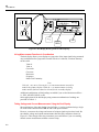
Operation is subject to the following two conditions:
•
This device may not cause harmful interference.
•
This device must accept any interference received, including interference that may
cause undesired operation.
There is no guarantee that interference will not occur in a particular installation. If this
equipment does cause interference to radio or television reception, which can be
determined by turning the equipment off and on, the user is encouraged to try to correct
the interference by one of more of the following measures:
•
Reorient the receiving antenna
•
Relocate the equipment with respect to the receiver
•
Move the equipment away from the receiver
•
Plug the equipment into a different outlet so that the computer and receiver are on
different branch circuits
If necessary, the user should consult the dealer or an experienced radio/television
technician for additional suggestions. The user may find the following booklet prepared
by the Federal Communications Commission helpful: How to Identify and Resolve
Radio-TV Interference Problems. This booklet is available from the U.S. Government
Printing Office, Washington, D.C. 20402. Stock No. 004-000-00345-4.
Declaration of the Manufacturer or Importer
We hereby certify that the Fluke Model 45 Dual Display MultiMeter is in compliance with
BMPT Vfg 243/1991 and is RFI suppressed. The normal operation of some equipment (e.g.
signal generators) may be subject to specific restrictions. Please observe the notices in the
users manual. The marketing and sales of the equipment was reported to the Central Office
for Telecommunication Permits (BZT). The right to retest this equipment to verify compliance
with the regulation was given to the BZT.
Table of Contents
Chapter
1
Title
Page
Introduction ........................................................................................ 1-1
Introducing the Fluke 45 Dual Display Multimeter........................................... 1-1
Options and Accessories .................................................................................... 1-2
Where to go from Here ...................................................................................... 1-2
2
Getting Started ................................................................................... 2-1
Introduction........................................................................................................
Getting Started ...................................................................................................
Unpacking and Inspecting the Meter.............................................................
Front Panel and Rear Panel ...........................................................................
Adjusting the Handle .....................................................................................
Line Power.....................................................................................................
Turning the Meter on .........................................................................................
Using the Pushbuttons........................................................................................
Selecting a Measurement Range ........................................................................
Automatic Input Terminal Selection..................................................................
Taking Some Basic Measurements ....................................................................
Measuring Voltage, Resistance, or Frequency ..............................................
Measuring Current.........................................................................................
Diode/Continuity Testing ..............................................................................
Operating the Meter Under Battery Power (Optional).......................................
Rack Mounting...................................................................................................
3
2-1
2-1
2-1
2-1
2-1
2-1
2-3
2-3
2-5
2-5
2-5
2-6
2-6
2-6
2-9
2-9
Operating the Meter From the Front Panel ....................................... 3-1
Introduction........................................................................................................
Front Panel Operations ......................................................................................
Display ...............................................................................................................
Primary Display.............................................................................................
Secondary Display.........................................................................................
Input Terminals..................................................................................................
Selecting a Measurement Function ....................................................................
Ranging..............................................................................................................
Autoranging...................................................................................................
Manual Ranging ............................................................................................
i
3-1
3-1
3-2
3-2
3-2
3-4
3-5
3-5
3-5
3-8
45
Users Manual
Measuring Frequency.........................................................................................
Frequency Ranging........................................................................................
Frequency Measurement Rates......................................................................
Measuring Frequency of Current (100 mA and 10A) Inputs.........................
Frequency Sensitivity Selection ....................................................................
Selecting A Function Modifier ..........................................................................
REL (Relative Readings) Modifier................................................................
dB (Decibels and Audio Power) Modifier.....................................................
HOLD (Touch Hold) Modifier ......................................................................
MN MX (Minimum Maximum) Modifier.....................................................
Using Function Modifiers in Combination....................................................
Selecting A Measurement Rate (Rate) ..........................................................
Using the S Button ....................................................................................
Using The Compare (Comp) Function...............................................................
The List and Number Editors ........................................................................
Using the List Editor .....................................................................................
Using the Number Editor...............................................................................
Power-Up Configuration....................................................................................
Factory Settings of Power-Up Configuration ................................................
Changing the Power-Up Configuration .........................................................
Calibration .........................................................................................................
4
3-8
3-8
3-9
3-9
3-9
3-10
3-11
3-12
3-13
3-13
3-13
3-14
3-14
3-16
3-16
3-17
3-18
3-19
3-19
3-19
3-20
Applications........................................................................................ 4-1
Introduction........................................................................................................ 4-1
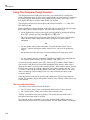
Using the Dual Display...................................................................................... 4-1
Using Measurement Functions in Combination ............................................ 4-2
Taking Voltage and Current Measurements Using the Dual Display ........... 4-2
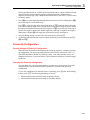
Response Times ................................................................................................. 4-4
How the Meter Makes Dual Display Measurements ......................................... 4-5
Updating the Primary and Secondary Displays with a Single Measurement 4-5
Updating the Primary and Secondary Displays with Separate Measurements 4-5
Update Rate in the Dual Display Mode......................................................... 4-7
External Trigger ................................................................................................. 4-7
Thermal Voltages............................................................................................... 4-8
When Measuring Resistance.............................................................................. 4-9
Two-Wire Configuration ............................................................................... 4-9
Correcting for Test Lead Resistance ............................................................. 4-9
True RMS Measurements .................................................................................. 4-9
Effects of Internal Noise in AC Measurements............................................. 4-10
Calculated (AC + DC) RMS Measurements ................................................. 4-10
Waveform Comparison (True RMS vs. Average-Responding Meters) ........ 4-10
5
Operating the Meter Using the Computer Interface ......................... 5-1
Introduction........................................................................................................
Local and Remote Operations .......................................................................
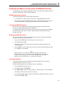
Preparing the Meter for Operations via the RS-232 Interface ...........................
Setting Communication Parameters (RS-232)...............................................
RS-232 Print-Only Mode...............................................................................
Cabling the Meter to a Host or Printer (RS-232)...........................................
Character Echoing and Deletion....................................................................
Device Clear Using ^C (CNTRL C)..............................................................
RS-232 Prompts.............................................................................................
Preparing the Meter to be Operated via IEEE-488 Interface .............................
IEEE-488 Operating Limitations...................................................................
ii
5-1
5-1
5-2
5-2
5-3
5-4
5-4
5-4
5-4
5-5
5-5
Contents (continued)
Installing the IEEE-488 Interface ..................................................................
Enabling the IEEE-488 Interface...................................................................
Addressing the Meter.....................................................................................
Cabling the Meter to a Host...........................................................................
Getting Started With An Installation Test..........................................................
Installation Test for RS-232 Operations ........................................................
Installation Test for IEEE-488 Operations ....................................................
If Test Fails....................................................................................................
How the Meter Processes Input .........................................................................
Input Strings ..................................................................................................
Input Terminators ..........................................................................................
Typical IEEE-488 Input Strings ....................................................................
Sending Numeric Values to the Meter ..........................................................
Sending Command Strings to the Meter........................................................
How the Meter Processes Output.......................................................................
Triggering Output ..............................................................................................
External Triggering from the Front Panel .....................................................
Setting the Trigger Type Configuration ........................................................
External Triggering via the Computer Interface............................................
Service Requests (IEEE-488 Only and Status Registers ...................................
Event Status and Event Status Enable Registers ...........................................
Status Byte Register ......................................................................................
Reading the Status Byte Register ..................................................................
Service Request Enable Register ...................................................................
Computer Interface Command Set.....................................................................
IEEE-488 Capabilities and Common Commands .........................................
Function Commands and Queries..................................................................
Function Modifier Commands and Queries ..................................................
Range and Measurement Rate Commands and Queries................................
Measurement Queries ....................................................................................
Compare Commands and Queries .................................................................
Trigger Configuration Commands.................................................................
Miscellaneous Commands and Queries.........................................................
RS-232 Remote/Local Configurations ..........................................................
Sample Program Using the RS-232 Computer Interface ...................................
Sample Programs Using the IEEE-488 Computer Interface..............................
6
5-5
5-5
5-5
5-6
5-6
5-6
5-6
5-7
5-7
5-7
5-7
5-8
5-8
5-8
5-11
5-11
5-11
5-12
5-12
5-13
5-16
5-17
5-17
5-18
5-19
5-19
5-22
5-22
5-25
5-26
5-27
5-27
5-28
5-29
5-30
5-31
Maintenance........................................................................................ 6-1
Introduction........................................................................................................
Cleaning .............................................................................................................
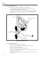
Line Fuse............................................................................................................
Current Input Fuses............................................................................................
Testing Current Input Fuses ..........................................................................
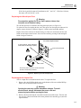
Replacing the 100 mA Input Fuse .................................................................
Replacing the 10 A Input Fuse ......................................................................
Self-Test Diagnostics and Error Codes..............................................................
Performance Tests..............................................................................................
Service ...............................................................................................................
Replacement Parts..............................................................................................
6-1
6-1
6-1
6-2
6-2
6-3
6-3
6-4
6-4
6-5
6-7
Appendices
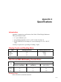
A Specifications .............................................................................................. A-1
B ASCII/IEEE-488 Bus Codes ....................................................................... B-1
C IEEE-488.2 Device Documentation Requirements ..................................... C-1
iii
List of Tables
Table
1-1.
3-2.
3-3.
3-4.
3-5.
3-6.
3-7.
3-8.
3-9.
3-10.
3-11.
3-12.
3-13.
4-1.
4-2.
4-3.
4-4.
4-5.
5-1.
5-2.
5-5.
5-6.
5-7.
5-8.
5-9.
5-11.
5-12.
5-13.
5-14.
5-15.
5-16.
5-17.
5-18.
6-1.
6-2.
Title
Accessories.............................................................................................................
Voltage Ranges and Full Scale Values...................................................................
Current Ranges and Full Scale Values ...................................................................
Ohms Ranges and Full Scale Values......................................................................
Frequency Ranges and Full Scale Values (Slow and Medium*) ...........................
Frequency Measurement Rates ..............................................................................
Maximum Sinewave Inputs for Frequency Measurements ....................................
Reference Impedances in Ohms .............................................................................
Display Measurement Rates for Single Function Measurements...........................
S Button Operations...........................................................................................
Options Available Through List Editor..................................................................
Number Editor Options ..........................................................................................
Power-Up Configuration Set at Factory.................................................................
Sample Dual Display Applications ........................................................................
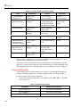
Typical Single Measurement Response Times (in Seconds) .................................
Typical Settling Delays (in Seconds) .....................................................................
Typical Measurement Intervals (in Seconds) for Dual Display Measurements.....
Ohms Test Voltage.................................................................................................
Factory Settings of RS-232 Communication Parameters.......................................
Approximate Print Rates in RS-232 Print-Only Mode...........................................
Status Register Summary .......................................................................................
Description of Bits in ESR and ESE ......................................................................
Description of Bits in the Status Byte Register*....................................................
IEEE-488 Interface Function Subsets ....................................................................
IEEE-488 Common Commands.............................................................................
Function Commands and Queries ..........................................................................
Function Modifier Commands and Queries ...........................................................
Range and Measurement Rate Commands and Queries.........................................
Measurement Queries.............................................................................................
Compare Commands and Queries..........................................................................
Trigger Configuration Commands .........................................................................
Miscellaneous Commands and Queries .................................................................
Remote/Local Configuration Commands...............................................................
Self-Test Error Codes.............................................................................................
Performance Tests for Volts, Diode Test, Ohms, and Frequency, Functions ........
v
Page
1-2
3-6
3-7
3-7
3-7
3-9
3-10
3-12
3-14
3-15
3-18
3-18
3-20
4-3
4-6
4-6
4-8
4-9
5-2
5-3
5-14
5-17
5-18
5-20
5-20
5-22
5-23
5-25
5-26
5-27
5-27
5-28
5-29
6-4
6-5
45
Users Manual
6-3.
6-4.
6-5.
Performance Tests for mA Current Functions ....................................................... 6-7
Performance Tests for A Current Functions........................................................... 6-7
Replacement Parts .................................................................................................. 6-7
vi
List of Figures
Figure
2-1.
2-2.
2-3.
2-4.
2-5.
2-6.
2-7.
2-8.
3-1.
3-2.
3-3.
3-4.
3-5.
3-6.
3-7.
4-1.
4-2.
4-3.
5-1.
5-2.
5-3.
5-4.
5-5.
5-6.
6-1.
6-2.
Title
Front Panel .............................................................................................................
Rear Panel ..............................................................................................................
Adjusting Handle....................................................................................................
Summary of Basic Pushbutton Operations.............................................................
Measuring Voltage, Resistance, or Frequency.......................................................
Measuring Current or Frequency ...........................................................................
Continuity Testing..................................................................................................
Diode Testing .........................................................................................................
Primary Display......................................................................................................
Display Annunciators.............................................................................................
Secondary Display..................................................................................................
Input Terminals ......................................................................................................
Function Selection Buttons ....................................................................................
Range Selection Buttons ........................................................................................
Function Modifier Selection Buttons .....................................................................
Dual Display Showing Volts AC and Frequency...................................................
DC Voltage and DC Current Measurement on Input Signal..................................
Waveform Comparison Chart ................................................................................
Typical IEEE-488 Input Strings .............................................................................
External Trigger Using Receive Pin (RX) of RS-232 Interface.............................
Overview of Status Data Structures .......................................................................
Event Status and Event Status Enable Registers ....................................................
Sample Program for RS-232 Computer Interface ..................................................
Sample Programs for IEEE-488 Computer Interface.............................................
Replacing the Line Fuse.........................................................................................
Replacing the 100mA Input Fuse...........................................................................
vii
Page
2-2
2-2
2-3
2-4
2-7
2-7
2-8
2-8
3-2
3-3
3-3
3-4
3-6
3-8
3-11
4-2
4-4
4-11
5-10
5-13
5-15
5-16
5-31
5-32
6-2
6-3
Chapter 1
Introduction
Introducing the Fluke 45 Dual Display Multimeter
Note
This manual contains information and warnings that must be followed to
ensure safe operation and retain the meter in safe condition.
W Warning
To avoid electric shock or injury, read the "multimeter safety"
sheet preceding Chapter 2 before using the meter.
The Fluke 45 Dual Display Multimeter (also referred to as "the meter") is a 4/2-digit
(30,000 count) meter with a 5-digit (100,000 count) high resolution mode. The meter is
designed for bench-top, field service, and system applications. Complete specifications
are provided in Appendix A.
With the (optional) IEEE-488 computer interface installed, the meter is fully
programmable for use on the IEEE Standard 488.1 interface bus(1987). The meter is also
designed in compliance with supplemental standard IEEE-488.2 (1987).
Some features provided by the meter are:
•
A dual, vacuum fluorescent, display that allows two properties of an input signal to
be displayed at the same time. (e.g., ac voltage in one display and frequency in the
other).
•
Remote operation via the RS-232 interface (included) or the IEEE-488 interface
(optional).
•
True rms ac
•
(AC + DC) rms, calculated
•
Frequency measurements to greater than 1 MHz
•
I µV sensitivity in volts dc
•
Decibels with variable reference impedance and audio power measurement
capability.
•
A compare mode to determine if a measurement is within, above, or below a
designated range.
1-1
45
Users Manual
•
100,000, 30,000, and 3,000 selectable count resolution, with display reading speeds
of 2.5, 5, and 20 readings per second (rps), respectively.
•
Built-in self-tests with closed-case calibration (no internal calibration adjustments).
Options and Accessories
Two options are available. These options can be installed in the meter at the factory or by
the customer on site:
•
The IEEE-488 Interface (Option -O5K) provides full programmability, and
automated calibration. The IEEE-488 computer interface command set is identical to
the RS-232 interface commands wherever possible.
•
The Battery Kit (Option -01 K) consists of a rechargeable, 8 V, lead-acid battery,
with battery bracket and charger assembly. The battery has a typical operating time
of eight hours and is fully operable at ambient temperatures between 0 and 50 °C. For
complete battery specifications, refer to Appendix A.
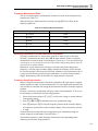
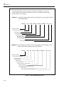
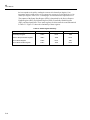
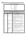
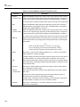
Available accessories are listed and described in Table 1-1.
Table 1-1. Accessories
Model
Description
C40
Soft carrying case. Provides padded protection for the meter. Includes a pocket for the
manual and pouch for the test leads and line cord.
M00-200-634
Rackmount Kit. Allows meter to be mounted on either the right or left side of a standard
19-inch rack.
RS40
RS-232 terminal interface cable. Connects the Fluke 45 to any terminal or printer with
®
®
properly configured DTE connector (DB-25 socket), including an IBM PC , IBM PC/XT
or IBM PS/2 (models 25, 30, 5O, P60, 70, and 80).
RS41
RS-232 modem cable. Connects the Fluke 45 to a modem with properly configured DB-25
male pin connector.
S45
QuickStart ™, a PC software package, simplifies operation of the Fluke 45 when using the
RS-232 computer interface. Readings are recorded in files that can be accessed by Lotus
®
®
1-2-3 , dBase lll and other graphics packages.
Y8021
Shielded IEEE-488 one-meter (39.4 inches) cable, with plug and jack at each end.
Y8022
Shielded IEEE-488 two-meter (78.8 inches) cable, with plug and jack at each end.
Y8023
Shielded IEEE-488 four-meter (13 feet) cable, with plug and jack at each end.
Where to go from Here
This manual has been organized to assist you in getting started quickly. It is not necessary
for you to read the entire manual before using the meter effectively. However, we recommend that you do so in order to use your meter to its full advantage.
Begin by scanning the Table of Contents to familiarize yourself with the organization of
the manual. Then, read Chapter 2, "GETTING STARTED". Refer to the appropriate
chapter of the manual as needed. The contents of each chapter are summarized below.
Chapter 1: Introduction
Introduces the Fluke 45 Dual Display Multimeter, describing its features, options, accessories, and users manual.
1-2
Introduction
Where to go from Here
1
Chapter 2: Getting started
Explains how to prepare the meter for operation and get started quickly taking basic
measurements from the front panel.
Chapter 3: Operating the meter from the front panel
Provides a complete description of each operation that can be performed using the pushbuttons on the front panel. Chapter 3 is organized so that related operations and functions
are grouped together.
Chapter 4: Applications
Describes how to use the meter in more advanced operations and sophisticated applications. Assumes a basic knowledge of the meter and front panel operations.
Chapter 5: Operating the Meter using the Computer Interface
Describes how to connect the meter to a terminal or host and operate it via the RS-232-C
or (optional) IEEE-488 interface. Assumes a basic knowledge of the meter and front
panel operations.
Chapter 6: Maintenance
Describes how to perform basic maintenance and repairs (e.g., replacing fuses) and how
to order replacement parts. Complete service and repair procedures are contained in the
"Fluke 45 Dual Display Multimeter Service Manual" (P/N 856042).
Appendices
A. Specifications
B. ASCII/ IEEE-488 Bus Codes
C. IEEE-488.2 Device Documentation Requirements
1-3
45
Users Manual
1-4
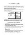
MULTIMETER SAFETY
The Fluke 45 Dual Display Multimeter has been designed and tested according to IEC
Publication 348, Safety Requirements for Electronic Measuring Apparatus. This manual
contains information and warnings which must be followed to ensure safe operation and
retain the meter in safe condition. Use of this equipment in a manner not specified herein
may impair the protection provided by the equipment.
The meter is designed for IEC 664, Installation Category II use. It is designed for use in
circuits with a VA rating of <4800 VA.
Some common international electrical symbols used in this manual are shown below.
B
AC - ALTERNATING
CURRENT
Y
F
DC - DIRECT
CURRENT
J
D
EITHER AC OR DC
CURRENT
W
FUSE
T
I
DANGEROUS
VOLTAGE
EARTH GROUND
SEE EXPLANATION
IN MANUAL
DOUBLE INSULATION
FOR PROTECTION
AGAINST ELECTRIC
SHOCK
Before using the meter, read the following safety information carefully. In this manual,
"WARNING," is reserved for conditions and actions that pose hazard(s) to the user;
"CAUTION," is reserved for conditions and actions that may damage your meter.
W WARNING
TO AVOID ELECTRICAL SHOCK OR OTHER INJURY:
•
•
•
•
•
•
•
•
•
•
•
•
•
Avoid working alone
Follow all safety procedures for equipment being tested.
Inspect the test leads for damaged insulation or exposed metal. Check test lead
continuity. Damaged leads should be replaced.
Be sure the meter is in good operating condition.
Select the proper function for your measurement.
To avoid electrical shock, use caution when working above 60V dc or 30V ac RMS.
Disconnect the live test lead before disconnecting the common test lead.
Disconnect the power and discharge high-voltage capacitors before testing in Ω and
LR.
When making a current measurement, turn the circuit power off before connecting
the meter in the circuit.
Check meter fuses before measuring transformer secondary or motor winding
current. (See Section 6, MAINTENANCE.") An open fuse may allow high voltage
build-up, which is potentially hazardous.
Use clamp-on probes when measuring circuits exceeding 10 amps.
When servicing the meter, use only the replacement parts specified.
Do not allow meter to be used if it is damaged or if its safety is impaired.
Chapter 2
Getting Started
Introduction
Chapter 2 explains how to prepare the meter for operation, discusses general operating
features, and walks you through the basics of taking some common measurements.
Getting Started
Unpacking and Inspecting the Meter
Carefully remove the meter from its shipping container and inspect it for possible damage
or missing items. If the meter is damaged or something is missing, contact the place of
purchase immediately. Save the container and packing material in case you have to return
the meter.
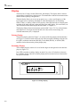
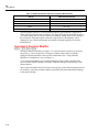
Front Panel and Rear Panel
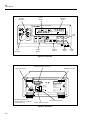
The front panel (shown in Figure 2-1.) has three main elements: the input terminals on
the left, the primary and secondary displays, and the pushbuttons. The pushbuttons are
used to select major functions, ranging operations, and function modifiers. These
elements are described in detail in Chapter 3.
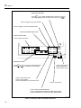
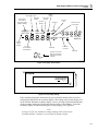
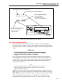
The rear panel (shown in Figure 2-2) contains the power-line cord connector, an RS-232
interface connector, a cutout for the (optional) IEEE-488 interface connector, a serial
number label, and a line fuse. (For fuse testing and replacement procedures, refer to
Chapter 6.) Rotate the rear feet 180 degrees before using the meter.
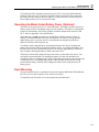
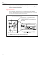
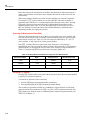
Adjusting the Handle
For bench-top use, the handle can be positioned to provide two viewing angles. To adjust
its position, pull the ends out to a hard stop (about 1/4-inch on each side) and rotate it to
one of the four stop positions shown in Figure 2-3. To remove the handle, adjust it to the
vertical stop position and pull the ends all the way out.
Line Power
WWarning
To avoid shock hazard, connect the instrument power cord to a
power receptacle with earth ground. A protective ground
connection by way of the grounding conductor in the power
cord is essential for safe operation.
2-1
45
Users Manual
Primary
Display
mA Fuse
Receptacle
45
V
DUAL DISPLAY MULTIMETER
REL AUTO
REMOTE SMF MAX dB
MIN HOLD
EXT TRG
mA
mVDCAC UNCAL mA
Mk Hz
10A
600V CAT I
1000V CAT I
Secondary
Display
!
mV DC AC
Mk Hz
CAL
ENABLE
100
mA
COM
Shift
Key
FUSE F1
500 mA
F 250V
V
FUSED
V
A
FREQ
REF#
REF
HOLD
MN MX
RATE
THRESH
ADDR
BAUD
AUTO
COMP
HI
LO
2ND
dB
REL
A
LOCAL
POWER
Input
Terminals
Ranging
Buttons
Function
Buttons
Modifier
Buttons
Reading
Rate
aam01f.eps
Figure 2-1. Front Panel
IEEE-488 Interface Connector*
RS-232 Connector
Serial Number Label
IEEE STD 488 PORT
C
R
US
LISTED
950 Z
SH1, AH1, T5, L4, SR1, RL1,
DC1, DT1, PPO, CO ,E1
RX
DTR
TX GND
IIII
1 2 3 4 5
6 7 8 9
WARNING:
TO AVOID ELECTRIC SHOCK DISCONNECT
MEASURING TERMINALS BEFORE OPENING
CASE
CAUTION:
FOR FIRE PROTECTION
REPLACE ONLY WITH
T 1/8A 250V (SLOW) FUSE
WARNING:
TO AVOID DAMAGE OR INJURY USE ONLY
IN CIRCUITS LESS THAN 4800VA
90-264V
50/60 Hz
20VA
FLUKE CORPORATION
MADE IN USA
PAT. 4,217,543 4,556,867 4,532,470 4,825,392
4,857,878 5,332,963 5,418,464 DES 311,700
RS-232C
*Available with IEEE-488
Interface Option only. Otherwise,
covered with insert
Line Power Fuse Housing
Power-Line Cord Connector
aam02f.eps
Figure 2-2. Rear Panel
2-2
Getting Started
Turning the Meter on
1. Viewing Position
2
2. Alternate Viewing Position
Pull End Out and Towards You.
Then Slide to Left.
3. Carrying Position
4. Removal Position
(to Remove, Pull Ends Out)
aam03f.eps
Figure 2-3. Adjusting Handle
If you have not already done so, plug the line cord into the connector on the rear of the
meter. The meter will operate on any line voltage between 90 V ac and 264 V ac without
adjustment, and any frequency between 45 and 440 Hz. However, it is only warranted to
meet published specifications at 50/60 Hz.
Turning the Meter on
To turn the meter on, press in the green, POWER button located on the lower-right of the
front panel. If the meter is being operated under battery power and you turn the meter off,
you must wait five seconds before turning the meter back on. If you do not, the meter will
not power-up.
When the meter is turned on, the primary and secondary displays light for about 4
seconds while the instrument performs an internal self-test of its digital circuitry. These
tests check RAM, ROM, A/ D, calibration, and the display. The meter has passed all tests
and is ready for normal operation if an error code is not displayed. However, if an error is
detected, the meter will still attempt to operate. (Refer to "Self-Test Diagnostics and
Error Codes" in Chapter 6.)
If any front panel button other than E is held down while the power-up sequence is in
progress, the entire display stays on until another button is pressed. Then, the powerup
sequence continues.
After the meter completes the power-up sequence, it assumes the power-up measurement
configuration stored in non-volatile memory. The power-up configuration set at the
factory is shown in Table 3-13. (To change the power-up configuration, refer to
"Changing the Power-Up Configuration" in Chapter 3.)
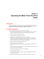
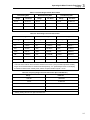
Using the Pushbuttons
The pushbuttons on the front panel select meter functions and operations. A summary of
basic pushbutton operations is shown in Figure 2-4.
Pushbuttons can be used in three ways. You can:
•
Press a single button to select a function or operation.
EXAMPLE: Press Z to select volts ac for the primary display.
Press a combination of buttons, one after the other.
2-3
45
Users Manual
2ND (SHIFT BUTTON):
-Press 2ND then a FUNCTION BUTTON to Select Function for
Secondary Display. (Refer to Section 3 for other uses of 2ND .)
-Press to Toggle In and Out of Decibels
-Press to Toggle In and Out of Relative Mode
FUNCTION MODIFIER BUTTONS
FUNCTION BUTTONS:
-Press to Select a Function
V
V
A
A
FREQ
AUTO
COMP
HI
LO
REL
dB
2ND
REF#
REF
LOCAL
HOLD
MN MX
RATE
THRESH
ADDR
BAUD
POWER
RANGE BUTTONS:
-Press
-Press
AUTO
-Press to Step Through
Measurement Rate
(Slow, Medium, Fast)
to Toggle In and Out of Manual Ranging;
or
to Up Range or Down Range
-Press to Select Touch Hold;
-Press to Force Update;
-Press and Hold Down for 2 Seconds to Exit.
-Press in to Power-Up
-Press to Select the MN MX Modifier;
-Press to Toggle Between Minimum and Maximum Reading;
-Press and Hold Down for 2 Seconds to Exit MN MX Mode.
aam04f.eps
Figure 2-4. Summary of Basic Pushbutton Operations
2-4
Getting Started
Selecting a Measurement Range
2
EXAMPLE: Press Z to select volts ac for the primary display, then press I to
select the decibels modifier.
•
Press multiple buttons simultaneously.
EXAMPLE: Press Z and Ysimultaneously to select true rms volts ac + volts dc
(calculated) in the primary display.
For more details on the uses of each button, refer to Chapter 3, "OPERATING THE
METER FROM THE FRONT PANEL."
Selecting a Measurement Range
Measurement ranges can be selected automatically by the meter in "autorange" or
manually by the user. In the autorange mode, the meter selects the appropriate range for
the measurement reading.
To manually select a range, press E to toggle in (and out) of the manual ranging mode,
or press U or T . In the manual range mode, press U or T to up range or down
range to the desired range. For more details on ranging, refer to "Ranging’’ in Chapter 3.
Automatic Input Terminal Selection
If current (ac or dc) is being measured in the autorange mode and there is no input on the
100 mA terminal, the meter switches automatically between the 100 mA and 10 A input
terminals looking for a signal. A front panel annunciator indicates that the meter is in the
mA range while the meter attempts to select the correct input terminal.
When a signal is detected at either input terminal, the display updates with the
measurement results. If an input signal is not found on either input terminal, a
measurement is taken on the mA terminal.
Automatic input terminal selection is disabled when the meter is in the manual ranging
mode. Use the Uand T buttons to select the appropriate current input terminal and
range.
Taking Some Basic Measurements
W Warning
Read “Multimeter Safety” before operating this meter.
The following procedures describe the basics of taking common measurements from the
front panel. These procedures are provided for the user who needs to get started quickly,
but does not want to read the rest of the manual at this time. However, in order to take
full advantage of your meter, you should read the remainder of this manual carefully and
completely.
W Warning
To avoid electrical shock or damage to the meter, do not apply
more than the rated voltage between any terminal and earth
ground. The meter is protected against overloads up to the
limits shown in Table 3-1. Exceeding these limits poses a
hazard to the meter and operator.
2-5
45
Users Manual
Measuring Voltage, Resistance, or Frequency
To measure voltage, resistance, or frequency, press the desired function button and
connect the test leads as shown in Figure 2-5. The meter will select the appropriate range
in the autorange mode, and an annunciator on the display will indicate measurement
units.
Note
After measuring high voltage to 1000 V dc, errors may occur when making
measurements with 1 to 10 µV resolution. Allow up to two minutes prior to
making low-level measurements.
Measuring Current
To measure current, insert the test leads in the 100 mA input terminal for currents up to
100 mA or in the 10 A input terminal for higher current. Press C or D and connect
the test leads as shown in Figure 2-6 and described in the following procedure:
1. Turn off power in the circuit to be measured.
2. Break the circuit (on the ground side to minimize the common mode voltage), and
place the meter in series at that point. (To measure current without breaking the
circuit, use a current clamp.)
3. Turn on power to the circuit, and read the display. The meter will select the
appropriate range automatically, and an annunciator on the display will indicate the
units of the measurement value shown.
4. Turn off power to the circuit and disconnect the meter from the tested circuit.
Note
After measuring high current using the 10 A input, thermal voltages are
generated that may create errors when making low-level (high sensitivity)
dc measurements of volts, current, or ohms. To make the most accurate
measurements, allow up to ten minutes for the thermals to settle out.
Diode/Continuity Testing
Diode and continuity tests are performed by a diode test function with a continuity beeper
that can be turned on and off.
The continuity test determines whether a circuit is intact (i.e., has a resistance less than
about 30 Ω). The meter detects continuity for intervals as brief as 50 µs. The continuity
test function cannot be selected for the secondary display.
To perform a continuity test, press G , and connect the test leads as shown in Figure
2-7. The beeper emits a single beep when the input drops below +0.8 V (approximately
1 kΩ), and emits a continuous tone when the input goes below +25 mV (approximately
30 Ω).
The diode test measures the forward voltage of a semiconductor junction (or junctions) at
approximately 0.7 mA. Readings are displayed in the 3 V range at the medium and fast
measurement rates. "OL" is displayed for voltages above +2.5 V. If the diode test is
performed at the slow reading rate, readings are displayed in millivolts on the 1000 mV
(1 V) range.
2-6
Getting Started
Taking Some Basic Measurements
+
VOLTAGE
SOURCE
45
V
DUAL DISPLAY MULTIMETER
10A
!
600V CAT I
1000V CAT I
-
2
CAL
ENABLE
100
mA
COM
FUSE F1
500 mA
F 250V
V
FUSED
V
dB
REL
A
A
FREQ
AUTO
COMP
LO
HI
2ND
REF#
REF
HOLD
MN MX
RATE
THRESH
ADDR
BAUD
LOCAL
POWER
V
FREQ
V
aam05f.eps
Figure 2-5. Measuring Voltage, Resistance, or Frequency
45
CURRENT
SOURCE
V
DUAL DISPLAY MULTIMETER
10A
600V CAT I
1000V CAT I
!
CAL
ENABLE
100
mA
COM
FUSE F1
500 mA
F 250V
FUSED
V
A
V
A
dB
REL
FREQ
AUTO
COMP
HI
LO
2ND
REF#
REF
HOLD
MN MX
RATE
THRESH
ADDR
BAUD
LOCAL
POWER
Note: Measurement can be also made using
current clamp without breaking circuit.
A
FREQ
A
aam06f.eps
Figure 2-6. Measuring Current or Frequency
2-7
45
Users Manual
+
45
TEST
CIRCUIT
V
10A
!
600V CAT I
1000V CAT I
-
DUAL DISPLAY MULTIMETER
CAL
ENABLE
100
mA
COM
FUSE F1
500 mA
F 250V
V
FUSED
REL
A
A
V
FREQ
AUTO
COMP
HI
LO
dB
2ND
REF#
REF
HOLD
MN MX
RATE
THRESH
ADDR
BAUD
LOCAL
POWER
Note: This is a Diode Test Function
with a Continuity Beeper.
aam07f.eps
Figure 2-7. Continuity Testing
45
V
DUAL DISPLAY MULTIMETER
10A
600V CAT I
1000V CAT I
!
CAL
ENABLE
100
mA
COM
FUSE F1
500 mA
F 250V
FUSED
V
V
REL
A
A
FREQ
AUTO
COMP
HI
LO
dB
2ND
REF#
REF
HOLD
MN MX
RATE
THRESH
ADDR
BAUD
LOCAL
POWER
aam08f.eps
Figure 2-8. Diode Testing
2-8
Getting Started
Operating the Meter Under Battery Power (Optional)
2
To perform a diode or transistor junction test, press G to select the diode/continuity
function. (Each press of G turns the continuity beeper on and off.) Then connect the
test leads across the diode as shown in Figure 2-8. Notice how the test leads are placed.
Reversing the polarity will reverse-bias the diode.
Operating the Meter Under Battery Power (Optional)
The meter can be powered by an 8 V, lead-acid battery. The battery module consists of a
battery, battery bracket, and battery charger circuit assembly. The battery is rechargeable,
requires no maintenance, and is fully operable at ambient temperatures between 0 and
50 °C. Refer to Appendix A for specifications.
The battery has a typical operating time of eight hours. When less than 1/2-hour of
battery life remains, N turns on. If you turn the meter off when it is being operated
under battery power, you must wait five seconds before turning the meter back on.
Otherwise the meter will not power-up.
To maintain a fully charged battery (and maximize battery life), always recharge the
battery after the meter has been operated on battery power. To recharge the battery, plug
the meter into line power and turn the meter off. It will take approximately 16 hours to
fully recharge a discharged battery with the meter turned off.
The battery remains fully charged as long as the meter is connected to line power. You
need not be concerned about over-charging the battery. Do not store the battery for
extended periods in a discharged state. Always fully charge the battery before storage and
at least once every six months during storage. If the meter has been stored for a long
period with the battery installed, fully recharge the battery before using the meter on
battery power.
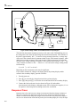
Rack Mounting
You can mount the meter in a standard 19-inch rack using the M00-200-634 Rack Mount
Kit. The rear feet can be rotated to clear a narrow rack space.
To install the rack mount kit, refer to the instructions provided with it.
2-9
45
Users Manual
2-10
Chapter 3
Operating the Meter From the Front
Panel
Introduction
Chapter 3 explains how to operate the meter from the front panel. Refer to Chapter 4 for
information concerning specific applications. Chapter 5 provides instructions on how to
operate the meter using the computer interface (RS-232 or IEEE-488).
Front Panel Operations
The following operations can be performed from the front panel:
•
•
Select a measurement function (volts dc, volts ac, current dc, current ac, resistance,
frequency, and diode/continuity test) for the primary and secondary display.
Take a measurement and display a reading.
•
Select the manual or autorange mode (AUTO).
•
•
•
Manually select a measurement range for the primary display.
Select function modifiers that cause the meter to display relative readings (REL),
minimum or maximum values (MN MX), or decibels (dB), or to enter the Touch
Hold mode (HOLD) to hold a reading on the primary display.
Change the measurement rate (slow, medium, fast).
•
Set the dB reference resistance (REF Ω).
•
Take a measurement and compare (COMP) it against a tolerance range (HI, LO, or
PASS).
•
Use the "editor" to select from option lists, to enter a relative base, or to enter a HILO
range for the compare (COMP) mode.
•
Configure the computer interface (RS-232 or IEEE-488).
•
Take an audio power reading.
•
Send measurements directly to a printer or terminal through the RS-232 interface
(RS-232 print-only mode).
These and other front panel operations are described in the remainder of Chapter 3.
3-1
45
Users Manual
Display
The meter has a 5-digit, vacuum-fluorescent, dual display. This display shows measurement readings, annunciators, and messages. The annunciators indicate measurement units
and the meters operating configuration.
The dual display allows you to see two properties (e.g., volts ac and frequency) of the
input signal you are measuring. Readings are taken and displayed in an alternating
fashion. That is, a reading is taken of one property of the input and sent to a display; then
a reading of the other property is taken and sent to the other display. (For more detail, see
"How the Meter makes Dual Display Measurements" in Chapter 4.)
The display flashes when a measurement exceeds 1000 V dc or 750 V ac, the maximum
rated input level. If an input exceeds the full scale value of the selected range, the
overload annunciator (OL) is displayed.
Primary Display
The primary display (shown in Figure 3-1) consists of the larger digits and annunciators
(see Figure 3-2) and is located on the left side of the front panel. Readings using the relative (REL), minimum maximum (MN MX), Touch Hold (HOLD), or decibels (dB)
modifiers can be shown on the primary display only.
Secondary Display
The secondary display consists of a set of smaller digits on the right side of the dual display (see Figure 3-3).
Press S to turn the secondary display on and off. A series of five dashes is shown in
the secondary display when the secondary display has been turned on but a function has
not yet been selected.
45
DUAL DISPLAY MULTIMETER
REL AUTO
REMOTE SMF MAX dB
MIN HOLD
EXT TRG
mA
mVDCAC
Mk Hz
aam09f.eps
Figure 3-1. Primary Display
3-2
Operating the Meter From the Front Panel
Display
Reading Rate:
Slow, Medium, Fast
Remote State
with or without
Front Panel Lockout
(REMS or RWLS))
3
Relative
Modifier
MIN MAX
Modifier
Touch Hold
Modifier
Decibels
Modifier
Autorange
Continuity
Test
Function and Unit
Annunciators
REL AUTO
REMOTE SMF MAX dB
MIN HOLD
EXT TRG
mA
mVDCAC UNCAL mA
Mk Hz
mV DC AC
MkW Hz
External
Trigger
Enabled
Less Than
1/2 Hour Battery
Power Remains
Calibration
Corrupted
Diode Test
Diode Test
Overload, Out of Limits.
(Placement of Decimal
Point Varies According
to Range.)
aam10f.eps
Figure 3-2. Display Annunciators
45
DUAL DISPLAY MULTIMETER
UNCAL mA
mV DC AC
Mk Hz
aam11f.eps
Figure 3-3. Secondary Display
If the secondary display has been turned on, press a function button (white) to select a
measurement function for the secondary display. The reading in the primary display will
not be affected. When the secondary display is active, pressing any function button turns
off the secondary display and selects that function on the primary display. To turn the
secondary display off without affecting the primary display, press S twice.
Note
If you press G, only a diode test voltage reading will be shown in the
secondary display; continuity is restricted to the primary display.
3-3
45
Users Manual
Neither function modifiers (REL, dB, HOLD, and MN MX) nor the manual range mode
can be selected in the secondary display. Measurement ranges in the secondary display
are always selected through autoranging.
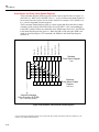
Input Terminals
The input terminals, shown in Figure 3-4, are located on the left of the front panel.
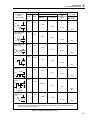
The meter is protected against overloads up to the limits shown in Table 3-1. Exceeding
these limits poses a hazard to both the meter and operator.
Volts, Ohms, Diode Test Input Terminal
Amperes Input Terminal. For Current Measurements up to
10A continuous (or 20A for 30 sec).
Milliamperes Input Terminal. For Current Measurements
up to 100mA.
V
10A
45
600V CAT I
1000V CAT I
!
V
600V CAT I
1000V CAT I
100
mA
COM
!
CAL
ENABLE
100
mA
COM
FUSE F1
500 mA
F 250V
FUSE F1
500 mA
F 250V
DUAL DISPLAY MULTIMETER
10A
FUSED
V
A
V
A
REL
FREQ
AUTO
COMP
HI
LO
dB
2ND
REF#
REF
HOLD
MN MX
RATE
THRESH
ADDR
BAUD
LOCAL
POWER
FUSED
Note: Frequency Measurements are Normally taken
from the VΩ
Input, although the 10A and
100mA Inputs can be used.
Common Terminal. Return Terminal for all Measurements.
aam12f.eps
Figure 3-4. Input Terminals
3-4
Operating the Meter From the Front Panel
Selecting a Measurement Function
3
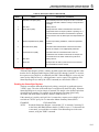
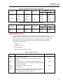
Table 3-1. Input Limits
FUNCTION
INPUT TERMINALS
MAXIMUM INPUT
|
VeG and COM
1000V dc
{ and FREQ
VeG and COM
750V ac rms, 1000V peak, 2 x 10 V-Hz
6
normal mode, or 1 x 10 V-Hz common
mode (whichever is less)
mAD and FREQ
100 mA and COM
300 mA dc or ac rms
\ and FREQ
10A and COM
10A dc or ac rms (or 20A dc or ac rms for
30 sec. Max)
e
VeG and COM
500V dc or ac rms on all ranges
G
VeG and COM
500V dc or ac rms
All Functions
Any terminal to earth
1000V dc or peak ac
7
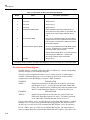
Selecting a Measurement Function
Press a function button (white), shown in Figure 3-5, to select a measurement function To
select ac + dc total rms readings, press Z and Y, or D and C, simultaneously.
When you select a function, annunciators turn on to indicate the function selected. If a
reading is shown on the secondary display when a function button is pressed, the
secondary display will be turned off.
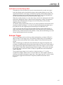
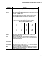
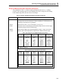
Ranges and full scale values are summarized in Table 3-2 for voltage, Table 3-3 for
current, Table 3-4 for ohms, and Table 3-5 for frequency.
Ranging
(E, U, T)
Ranging operations are performed using the E, U, and T buttons (see Figure 3-6).
Autoranging
When you are in the autorange mode, the AUTO annunciator is lit.
In autorange, the meter automatically selects the next higher range when a reading is
greater than full scale. If no higher range is available, "OL" (overload) is displayed on the
primary or secondary display. The meter automatically selects a lower range when a reading is less than approximately 9 % of full scale.
3-5
45
Users Manual
Amps DC
Volts DC
Resistance
Diode Test/Continuity
V
A
V
A
FUNCTION BUTTONS:
FREQ
-Press to Select the Function Designated
Volts AC
Amps AC
45
V
Frequency
DUAL DISPLAY MULTIMETER
10A
600V CAT I
1000V CAT I
!
CAL
ENABLE
100
mA
COM
FUSE F1
500 mA
F 250V
FUSED
V
A
V
A
REL
FREQ
AUTO
COMP
LO
HI
dB
2ND
REF#
REF
HOLD
MN MX
RATE
THRESH
ADDR
BAUD
LOCAL
POWER
aam13f.eps
Figure 3-5. Function Selection Buttons
Table 3-2. Voltage Ranges and Full Scale Values
Fast Reading Rate
Range
Range
Full Scale
Slow Reading Rate
Range
Full Scale
300 mV
300.0 mV
300 mV
300.00 mV
100 mV
99.999 mV
3V
3.000 V
3V
3.0000 V
1000 mV
999.99 mV
30 V
30.00 V
30 V
30.000 V
10 V
9.9999 V
300 V
300.0 V
300 V
300.00 V
100 V
99.999 V
1000 V*
1000 V*
1000 V*
1000.0 V*
1000 V*
999.99 V*
* 750V for volts ac
3-6
Full Scale
Medium Reading Rate
Operating the Meter From the Front Panel
Ranging
3
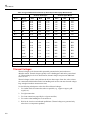
Table 3-3. Current Ranges and Full Scale Values
Fast Reading Rate
Range
Medium Reading Rate
Full Scale
Range
Full Scale
Slow Reading Rate
Range
Full Scale
30 mA
30.00 mA
30 mA
30.000 mA
10 mA
9.9999 mA
100 mA
100.0 mA
100 mA
100.00 mA
100 mA
99.999 mA
10 A
10.00 A*
10 A
10.000 A*
10 A
9.9999 A
* 20 A for maximum of 30 seconds
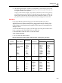
Table 3-4. Ohms Ranges and Full Scale Values
Fast Reading Rate
Range
Full Scale
Medium Reading Rate
Range
Full Scale
Slow Reading Rate
Range
Full Scale*
300 Ω
300.0 Ω
300 Ω
300.00 Ω
100 Ω
98.000 Ω
3 kΩ
3.000 kΩ
3 kΩ
3.0000 kΩ
1000Ω
980.00 Ω
30 kΩ
30.00 kΩ
30 kΩ
30.000 kΩ
10 kΩ
9.8000 kΩ
300 kΩ
300.0 kΩ
300 kΩ
300.00kΩ
100 kΩ
98.000 kΩ
3 MΩ
3.000 MΩ
3 MΩ
3.0000 MΩ
1000 kΩ
980.00 kΩ
30 MΩ
30.00 MΩ
30 MΩ
30.000 MΩ
10 MΩ
9.8000 MΩ
300 MΩ
300 MΩ
300 MΩ
300.0 MΩ
100 MΩ
98.0 MΩ**
*Typical
** Because of the method used to measure resistance, the 100 M (slow) and 300 M (medium and fast)
ranges cannot measure below 3.125 M and 20 M respectively. "UL" (Underload) is shown on the display
for resistances below these nominal points, and the computer interface outputs "+1 E-9".
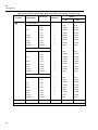
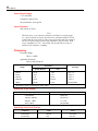
Table 3-5. Frequency Ranges and Full Scale Values (Slow and Medium*)
Range
Full Scale
1000 Hz
999.99 Hz
10 kHz
9.9999 kHz
100 kHz
99 999 kHz
1000 kHz
999.99 kHz
1 MHz
9.9999 MHz
* Fast (F) reading rate has one digit of resolution less.
3-7
45
Users Manual
Press to Toggle In and Out of Manual Ranging.
"AUTO" Annunciator Turns off when Manual Range Selected.
Press to Enter Manual Range and Up Range
Press to Enter Manual Range and Down Range
AUTO
45
V
DUAL DISPLAY MULTIMETER
10A
600V CAT I
1000V CAT I
!
CAL
ENABLE
100
mA
COM
FUSE F1
500 mA
F 250V
FUSED
V
A
V
A
REL
FREQ
AUTO
COMP
HI
LO
dB
2ND
REF#
REF
HOLD
MN MX
RATE
THRESH
ADDR
BAUD
LOCAL
POWER
aam14f.eps
Figure 3-6. Range Selection Buttons
Manual Ranging
Press E to toggle in and out of manual ranging. The range you are in when you enter
the manual range mode becomes the selected range.
In manual range, the meter remains in the selected range regardless of input. Press E to
toggle back to autoranging. Manual ranging can only be performed on readings shown on
the primary display; the secondary display always autoranges.
Press U to up range. If the U is pressed when the meter is still in autorange, manual
ranging is selected, the AUTO annunciator turns off, and the next higher range is selected
(if there is one).
Press T to down range. If the T is pressed when the meter is still in autorange,
manual ranging is selected, the AUTO annunciator turns off, and the next lower range is
selected (if there is one).
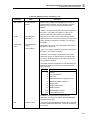
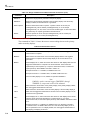
Measuring Frequency
(F)
Frequency Ranging
Frequency measurements from 5 Hz to > 1 MHz are automatically ranged so that a
frequency measurement is always displayed with maximum resolution.
If the frequency function (FREQ) is selected in the primary display, press the Uor T
to manually select a range. (Manual ranging is not allowed in the secondary display.) If
you select a frequency range manually, frequency measurements that exceed the full
scale value of that range cause "OL" (overload) to be displayed. Refer to Table 3-5 for
frequency ranges and full scale values.
3-8
Operating the Meter From the Front Panel
Measuring Frequency
3
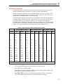
Frequency Measurement Rates
The rate at which frequency measurements are taken is a factor of the frequency being
measured (see Table 3-6).
When the frequency function has been selected, pressing R has no effect on the
frequency update rate.
Table 3-6. Frequency Measurement Rates
Frequency
Reading Rate
@ > 150 Hz
1.8/sec
@ 100 Hz
1.6/sec
@ 60 Hz
1.3/sec
@ 15 Hz
1/1.2sec
@10Hz
1/1.7sec
@5Hz
1/3.2 sec
Measuring Frequency of Current (100 mA and 10A) Inputs
Frequency measurements are always taken using the ac input circuitry of the meter.
Normally, measurements are taken on the Xinput terminal. However, frequency
measurements can also be taken on current inputs. If frequency is to be measured using a
current input, ac current must be selected in the primary display and frequency must be
selected in the secondary display.
When the ac current function in a mA range is selected in the primary display and
frequency is selected as the secondary display function, the frequency of the current at
the 100 mA terminal will be measured. Similarly, when the ac current function in the 10
A range is selected for the primary display and frequency is selected in the secondary
display, the frequency of the current at the 10 A input terminal is measured.
Frequency Sensitivity Selection
Before a frequency measurement is started, the amplitude of the input signal is sampled
and the optimum ac range is selected automatically. For most applications, therefore, the
user need not be concerned with setting the measurement sensitivity for stable frequency
readings.
However, if necessary, measurement sensitivity can be selected manually. To do so, use
the dual display as described in the following procedure:
1. Power-up the meter and press Zor D to select an ac voltage or current function
in the primary display.
2. Press E ,U, or T to manually select an ac measurement range.
3. Press S then press F to select the frequency function in the secondary display.
All frequency measurements on the secondary display will be taken on the selected
ac range.
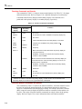
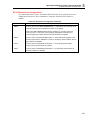
The maximum input voltage that may be applied on any ac measurement range for
reliable frequency measurements is listed in Table 3-7.
The minimum signal for a stable frequency measurement varies depending on the
frequency and waveform being measured.
3-9
45
Users Manual
Table 3-7. Maximum Sinewave Inputs for Frequency Measurements
Range
Maximim Input Voltage
300 mV
1 V rms
3V
6 V rms
30 V
60 V rms
300 V
750 V rms
750 V
750 V rms
The input signal sensitivity is listed under the frequency specifications in Appendix A.
These values are based on sine waveforms. The signal level must be increased for lower
crest factor inputs (the crest factor is the ratio of the peak voltage to the ac rms voltage of
the waveform). If the input signal is below the required level, the frequency will be
displayed as zero. If the measurements are unstable, the input signal may be near the
threshold level.
Selecting A Function Modifier
(K, I, H, J)
Selecting a function modifier (see Figure 3-7) causes the meter to perform an action on
an input (e.g., convert to decibels or compare to another value) before a reading is
displayed. Function modifiers can be used in combination. (See “Using Function
Modifiers in Combination," later in Chapter 3.)
To use a function modifier, press a function button to select a primary function, then
press a function modifier button (or buttons). Modified readings are shown only on the
primary display.
After a function modifier has been selected, pressing any (white) function button turns off
all modifiers, causes the secondary display to go blank, and returns unmodified readings
to the primary display.
3-10
Operating the Meter From the Front Panel
Selecting A Function Modifier
3
-Press to Toggle In and Out of Relative Modifier
-Press to Toggle In and Out of Decibels Modifier
REL
dB
HOLD
MN MX
-Press to Select MN MX Modifier;
-Press to Toggle Between Minimum
and Maximun Reading;
-Press and Hold Down for 2
Seconds to Exit MN MX Modifier.
45
V
-Press to Select Touch Hold Modifier;
-Press to Force New Reading;
-Press and Hold Down for
2 Seconds to Exit.
DUAL DISPLAY MULTIMETER
10A
600V CAT I
1000V CAT I
!
CAL
ENABLE
100
mA
COM
FUSE F1
500 mA
F 250V
FUSED
V
V
REL
A
A
FREQ
AUTO
COMP
HI
LO
dB
2ND
REF#
REF
HOLD
MN MX
RATE
THRESH
ADDR
BAUD
LOCAL
POWER
aam15f.eps
Figure 3-7. Function Modifier Selection Buttons
REL (Relative Readings) Modifier
When the relative modifier (REL) is selected, the reading on the primary display is
always the difference between the relative base and an input measurement. For example,
if the relative base is 15.000 V, and the present reading is 14.100 V, the display will show
-0.900.
WWarning
To avoid electrical shock or damage to the meter, note that a
relative reading may not indicate the presence of dangerous
voltages at the input connectors or test leads.
Press K to toggle in and out of the relative modifier. When the relative modifier is
selected: the last valid reading is stored as the relative base, the primary display zeroes
out, and "K" is shown on the primary display. (The secondary display is unaffected.)
To edit the relative base, use the number editor as described in "Using the Number
Editor" later in Chapter 3).
Note
The relative modifier cannot be selected I the display shows "OL" or is
blank. (The display would be blank, for example, because of external
triggering or range changes.)
Selecting the relative modifier K turns off autoranging and locks in the present range.
Make sure you are in the correct range before selecting the relative modifier. If you press
U or T after the relative modifier has been selected, you will automatically exit K.
When you are in REL, the relative base can be shown in the secondary display by
pressing S and, while holding it down, pressing K. Now, whenever the relative
3-11
45
Users Manual
modifier is selected, the relative base is shown in the secondary display. To turn off this
feature, press S and, while holding it down, press K .
dB (Decibels and Audio Power) Modifier
The decibels modifier takes a voltage measurement, converts it to dBm (measure of
decibels relative to one milliwatt), and displays the result on the primary display.
Press I to toggle in and out of the decibels modifier. When the decibels modifier is
selected, "dB" is shown on the primary display.
Decibels can be selected only when a voltage function is selected on the primary display
(volts ac, volts dc, or volts ac + dc). Decibels are always displayed in a single, fixed
range with 0.01 dB resolution. However, the basic measurement itself (e.g. volts ac)
autoranges.
A voltage measurement is converted to dBm using the following formula:
dBm = 10*log (1000*value2/reference impedance)
where "value" is the measurement value. The reference impedance can be set to any of 21
reference impedances listed in Table 3-8 by using the list editor as described in "Using
the List Editor" later in Chapter 3.
Table 3-8. Reference Impedances in Ohms
8000
300
93
1200
250
75
1000*
150
50
900
135
16†
800
125
8†
600
124
4†
500
110
2†
* Voltage annunciator lit
† Audio power readings possible
To access the reference impedance list, press S then press I (REF e). The reference
impedance currently selected is displayed, along with the db and e annunciators. Press
U or T to scroll to the desired value, then press E to select a reference impedance
and return the primary display to the measurement function. Press any function (white) or
modifier (light grey) button to exit the reference impedance list without selecting a new
value.
Setting the dB reference resistance to 16, 8, 4, or 2 ohms allows you to use the meter to
calculate audio power. After the reference resistance has been set to 16, 8, 4, or 2 ohms,
press I twice to select the audio power modifier. "POWER" will be shown on the
secondary display.
The following equation is used to make a power calculation:
Audio power = Volts /reference resistance
where volts is the measurement value.
3-12
Operating the Meter From the Front Panel
Selecting A Function Modifier
3
HOLD (Touch Hold) Modifier
The Touch Hold modifier allows you to take a measurement and "hold" that
measurement on the display. This feature can be particularly advantageous in difficult or
hazardous circumstances when you might want to keep your eyes fixed on the probes,
and then read the display when it is safe or convenient to do so. When a new, stable
reading is detected, a beep is emitted, and the display is automatically updated.
Press H to select the Touch Hold modifier. When Touch Hold is selected, "HOLD" is
shown in the primary display. In Touch Hold, each press of H forces a new reading to
be displayed. To exit Touch Hold, press down H for two seconds.
If you are in the autorange mode when Touch Hold is selected, you will autorange to the
correct range. If you are in the manual range mode, you will enter Touch Hold in the
selected (fixed) range you were in when Touch Hold was selected.
The Touch Hold modifier can be combined with the MN MX modifier to hold and update
only when a new minimum or maximum value is detected. Pressing H less that two
seconds when Touch Hold has been selected forces the display to update.
The meter allows you some choice when it comes to determining the minimum response
level needed for Touch Hold to capture and display a measurement. You can choose
among three Touch Hold sensitivity levels:
•
Level 1 (5 % of range)
•
Level 2 (7 % of range)
•
Level 3 (8 % of range)
To change this level, press S, then press H . The number “1,” “2,” “ or “ 3 “appears
on the primary display. Press U or T to step to the desired sensitivity level. Then
press E to set the level and return the primary display. You can return to the primary
display without changing the sensitivity level by pressing any button except E , U ,
or T .
MN MX (Minimum Maximum) Modifier
The MN MX modifier causes the meter to store the minimum and maximum inputs
measured since the MN MX modifier was selected.
Press J to select the MN MX modifier. When the MN MX modifier is first selected,
the minimum and maximum values are set to the displayed reading and the "MIN"
annunciator lights. Press J again to display the maximum reading (and the "MAX"
annunciator). Each subsequent press of the J button toggles between the minimum and
maximum measurements taken. To exit the MN MX modifier, press and hold down the
J button for two seconds.
Selecting the MN MX modifier turns off autoranging and locks in the present range.
Make sure you are in the correct range before selecting the MN MX modifier. If you
press U or T after MN MX has been selected, you will automatically exit the MN
MX modifier.
To observe the quantity being measured without resetting the stored MN MX values, use
the secondary display by pressing S , then select the same measurement function that
is selected for the primary display.
Using Function Modifiers in Combination
The meter allows you to use multiple function modifiers (dB, REL, HOLD, MN MX)
simultaneously. The selected modifiers are evaluated in the following order: HOLD, dB,
MN MX, and REL. That is, the meter first looks for a stable measurement for Touch
3-13
45
Users Manual
Hold, then converts the measurement to decibels, then determines if the measurement is
either a new minimum or maximum value, and then subtracts the relative base from the
measurement.
When using multiple modifiers, the order in which modifiers are selected is important.
For example, if K is pressed when you are in the MN MX, either the minimum or
maximum value (which ever is currently displayed) becomes the relative base. Pressing
J again as the next action causes the meter to display the difference between the
minimum and maximum value. If, on the other hand, J is pressed when you are in
REL, the difference between the relative base and the minimum or maximum value
(depending on what was displayed) is shown.
Selecting A Measurement Rate (Rate)
The meter takes measurements at one of three, user-selectable rates: slow, medium, and
fast. Rate selection allows you to maximize either measurement speed or noise rejection,
which affects accuracy (see Table 3-9). The rate selected is indicated by "S." "M," "F"
(slow, medium, or fast, respectively) in the primary display.
Press R , located in the lower-right corner of the front panel, to step through
measurement rates. The selected rate applies to all basic measurements, except frequency.
(When frequency is measured, the rate is a factor of the frequency being measured (see
Table 3-6), and pressing R has no effect on the frequency update rate.)
Table 3-9. Display Measurement Rates for Single Function Measurements
Measurement Rate
Digits
Display Counts
Results Per Second
Slow
5
99,999*
2-1/2
Medium
4-1/2
30,000
5
Fast
3-1/2
3,000
20
* All ranges and functions except ohms will display up to 99999. Ohms displays up to 98000 (typical).
Using the S Button
Pressing S (located on the lower-right of the front panel) causes the next button pushed
to perform a second level operation.
A second level operation can be selected by:
•
Pressing S then pressing another button (or buttons);
•
Pressing and holding down S and pressing another button;
The second level operation available on a pushbutton is engraved below it on the front
panel and enclosed in parentheses in Table 3-10. (The LOCAL function associated with
S operates only when the meter is in REMS [remote without front panel lockout]. See
Table 5-l5 in Chapter 5.)
3-14
Operating the Meter From the Front Panel
Selecting A Function Modifier
3
Table 3-10. S Button Operations
Pushbuttons
Operations
S then Z
Show volts ac reading in secondary display
S then Y
Show volts dc reading in secondary display
S then D
Show amperes ac reading in secondary display
S then C
Show amperes dc reading in secondary display
S then O
Show ohms reading in secondary display
S then F
Show Hz reading in secondary display
S then G
Show diode test reading in secondary display
S then E
Compare mode in primary display. (See "Using the Compare Function” in Chapter
3, below.)
(COMP)
S then T
(LO)
S then U
(Hi)
S and T
(LO)
S and U
Edit Compare mode low point. (See "Using the Compare Function" in Chapter 3,
below.)
Edit Compare mode high point. (See "USING THE COMPARE FUNCTION” in
Chapter 3, below)
Store value on primary display as LO compare point (See "USING THE
COMPARE FUNCTION" in Chapter 3, below.)
(Hl)
Store value on primary display as Hl compare point (See "USING THE COMPARE
FUNCTION" in Chapter 3, below.)
S then K
Edit relative base. (See "Using the List and Number Editor" in Chapter 3 below.)
(REF # )
S and K
Toggle display of relative base in secondary display.
S then H
Select Touch Hold sensitivity threshold
(THRESH)
S then I
Select dB reference impedance.
S then J
(ADDR)
Select computer interface address for IEEE-488 operations or RS-232 print only
rate. (See also "RS-232 Print-Only Mode" in Chapter 5.)
S then R
Select RS-232 baud rate or "IEEE" to enable an installed IEEE-488 interface.
(REF e)
(BAUD)
S Then S
Turn off secondary display, leaving primary display unaffected.
S and E
Store present operating configuration of meter as power-up configuration. (See
"Changing the Power-Up Configuration" later in Chapter 3.)
S and R
Display software version.
3-15
45
Users Manual
Using The Compare (Comp) Function
The compare function (COMP) provides an easy way to determine if a reading falls
within a designated range of values. In the compare mode, the meter displays a reading in
the primary display and indicates in the secondary display if that value is lower (LO)
than, higher (HI) than, or within a range (PASS) you selected.
The compare function can be used with any other function modifier — i.e., REL, MN
MX, HOLD, or dB.
Before selecting the compare function, set the high and low points of the tolerance range
that a reading will be compared against. This can be done in three ways:
•
Set the high and low compare points to the present reading by pressing and holding
down S , and then pressing either U (HI) or T (LO).
The value presently displayed becomes either the high or low point. If the display is
blank, the meter emits a beep and previously set high or low point remains
unchanged.
OR
•
Use the number editor, as described under "Using the Number Editor" later in
Chapter 3. (Before entering the number editor, be sure you are in the appropriate
range.)
The decimal point and input range are fixed according to the range in the editor.
OR
•
Use the computer interface commands COMPHI and COMPLO to set the high and
low compare points remotely. (Refer to Chapter 5 and Table 5-13.)
To select the compare function, press S , then press E (COMP). When COMP is
first selected, Touch Hold is also activated (and annunciated). Before a stable value is
detected, two dashes are shown in the secondary display. When a stable value is detected,
the meter emits a beep, the reading is displayed in the primary display, and "HI", "LO",
or "PASS" is shown in the secondary display. If the value is either HI or LO, the meter
emits a second beep. (If the reading is near zero, only two dashes are shown in the
secondary display.)
Touch Hold can be turned off by pressing and holding down H for longer than one
second. The secondary display then updates each time a new reading is taken, but a beep
is not sounded.
The List and Number Editors
Two editors can be invoked from the front panel:
•
The "list editor" allows you to scroll through and select from a list of options.
•
The "number editor" allows you to edit or enter a numeric value.
"Editing" is performed in the primary display. The normal operation of the meter is
interrupted when either editor is invoked.
If a computer interface command is received by the meter during editing, the edit is
aborted, and the meter returns to normal operation. The item being edited is not changed.
3-16
Operating the Meter From the Front Panel
Using The Compare (Comp) Function
3
Using the List Editor
Use the list editor to select an option from a list. Table 3-11 summarizes the options
available through the list editor.
To use the list editor, proceed as follows:
1. Press S .
2. Press the appropriate modifier button, as indicated in Table 3-11, to call the list editor
on an options list.
The option currently selected is shown in the primary display and an annunciator,
indicating the option list, is shown in the secondary display.
3. Press U or T to step through the list. (Holding down either button for longer
than two seconds causes it to scroll.)
4. As you step through the list, only the selected option is shown in normal intensity
(bright), all others are dimmed. When the desired option is shown, press E to
select it. The selected option is then displayed in normal intensity.
To abort the operation, press any button except E, U , and T. When the option
selection operation is aborted, the editor is exited, and the meter resumes normal
operation.
For example, to set the decibel reference impedance to 16:
1. Press S , then press I .
“e”, “dB”, and the reference impedance are shown in the primary display.
2. Press and hold down T to scroll to 16. (If the refernce impedance is less than 16,
press and hold down U.) Each option other than the selected reference impedance
is dimmed. Also, since power can be selected with this reference, "POWER" is
shown in the secondary display.
3-17
45
Users Manual
Table 3-11. Options Available Through List Editor
To Set
Pushbuttons
Touch Hold Minimum
Response Level
S then H
Decibel Reference
Impedance in Ohms
RS-232 Baud Rate
Options
Annunciator
"1" (5 % of range);
"2" (7 % of range); or
"HOLD"
"3" (8% of range)
S then I
2, 4,8,16,50,75,93,
110,124,125,135,150,
250, 300,500,600, 800,
900,1000,1200, or 8000
"dB" and “e“;
also "V" when
1000Ω
S then R
300,600,1200,2400,
4800, or 9600
"baud"
(BAUD)
Parity options list
displayed
"E" (even), "O" (odd),
"no" (none)
"PAR" for parity
Echo Mode
On or Off
"Echo" and "On"
or "OFF"
IEEE-488 Address(If
IEEE-488 Interface
Installed and selected.)
S then J
Valid addresses between
0-30
"IEEE"
RS-232 PrintOnly
Mode (If RS-232
Interface Selected)
S then T
1,2,5,10,20,50,100, 200,
500,1000,2000,
5000,10000,20000, or
50000
"PRINT"
Trigger Type
E and T
1,2,3,4, 5 (See Table 514.)
"tri"
(THRESH)
(REF e)
(ADDR)
(ADDR)
simultaneously
3. When you have scrolled to 16, press E to set the dB reference impedance. "16" now
becomes bright, indicating that it is the selected value.
This dB reference will remain selected until you change it (as described above), turn the
meter off, or reset the meter to the power-up configuration by pressing and holding down
E during power-up. (See "Changing the Power-Up Configuration" later in Chapter 3.)
Using the Number Editor
Use the number editor to set the relative base, or the low (LO) and high (HI) points for
compare (COMP) operations (see "Using the Compare Function" earlier in Chapter 3).
To use the number editor, proceed as follows:
1. To invoke the desired number editor, press S then press U , T , or K (REF
#). See Table 3-12
Table 3-12. Number Editor Options
Pushbuttons
3-18
Number Editor Invoked On
S then T (LO)
Low Point for Compare Mode
S then U (Hi)
High Point for Compare Mode
S then K (REF #)
Relative Base
Operating the Meter From the Front Panel
Power-Up Configuration
3
The last number entered (or, in REL, the last measured value) is shown with the left most
digit displayed in normal intensity and the remaining digits dim. (If the number is
negative, the minus sign is dim.) Related annunciators are lit, and "EDIT" is shown in the
secondary display.
2. Press U to step the bright digit through numbers between O and 9. Holding down U
causes this digit to scroll continuously.
Press T to select the digit to be edited. Each press of T causes the digit to the right
to be selected and go bright, while causing the previously selected digit to go dim. When
the right most digit has been selected, the next press of T selects the sign: if the sign is
positive, the negative annunciator flashes bright dim; if the sign is negative, the negative
annunciator is bright. U will toggle the sign between positive and negative.
3. Any time during editing, you can store a selected value by pressing E.
4. To abort the edit and return the meter to normal operation, press any button except E,
U, and T .
Power-Up Configuration
Factory Settings of Power-Up Configuration
When the meter is turned on and completes the power-up sequence, it assumes its powerup configuration. The power-up configuration set at the factory is shown in Table 3-13.
The IEEE-488 address, the RS-232 baud rate, parity, echo, and print-only rate are not
changed when power is cycled off and on. These parameters remain as set until changed
by the user.
Changing the Power-Up Configuration
You can change the power-up configuration to one that more closely meets your needs
and preferences. Any combination of meter parameters can become the power-up
configuration.
To save any configuration in which the meter is operating, press S and, while holding
it down, press E. The following parameters are saved:
•
Measurement function and initial range on primary display.
•
Measurement function and initial range on secondary display.
3-19
45
Users Manual
Table 3-13. Power-Up Configuration Set at Factory
Parameter
Configurations
Function Setting
DC volts
Range Mode
Autorange
Reading Rate
Medium (30,000 counts @ 5 readings/second)
Touch Hold Sensitivity Level
Level "2" (1 to 2 % of Range)
Reference Impedance (for dB)
600 ohms
High/Low Values for Compare (COMP) Mode
0
Minimum and Maximum values in MN MX Modifier
0
Relative Base
0
Relative Base in Secondary Display
Disabled
Trigger Type
Internal
•
Range mode on primary display (manual or autorange).
•
Measurement rate ("S" (slow) "M" (medium) or "F" (fast)).
•
Dual display status (active or inactive).
•
Any combination of selected function modifiers (MIN or MAX, HOLD, dB or dB
POWER, REL, and COMP).
•
Touch Hold sensitivity level (“1”, “2”, or “3”).
•
dB reference impedance (see Table 3-8 for available values).
•
Last recorded minimum and maximum values for MN MX modifier.
•
Last recorded relative base.
•
Relative base shown in secondary display (enabled or disabled).
•
Last HI-LO settings in compare mode.
•
Trigger type (see Table 5-3 for available trigger types).
•
Echo (on or off)
To restore the power-up configuration to the factory settings and erase any user-defined
configuration, press and hold down E, while turning the meter on. The meter beeps
when the factory settings are restored.
Calibration
The CAL ENABLE button is located in the lower-right corner of the display. Press and
Hold for three seconds to enable calibration. The meter allows for closed case calibration
using reference sources. See the Fluke 45 Dual Display Multimeter Service Manual (P/N
856042) for calibration procedures.
3-20
Chapter 4
Applications
Introduction
Chapter 4 discusses some applications that will help you use the meter effectively. These
applications assume you are familiar with the basic operation of the meter and have a
basic understanding of electronics. A sophisticated understanding of electrical circuits is
not necessary.
Using the Dual Display
Using the dual display effectively and with ingenuity can greatly enhance your test and
measurement capabilities. By allowing you to make several measurements on a particular
input signal, the dual display makes it easy to take measurements that in the past required
you to use two meters or make a series of measurements.
To see the ease with which the dual display can be used to take a reading of the ac
component of a signal on one display and its frequency on the other, perform the
following procedure to measure the voltage and frequency of line power:
1. Press in POWER to turn the meter on.
2. Plug the test leads into the X and COM input terminals.
3. Press Z to select volts ac for the primary display.
4. Press S , then press F to select frequency for the secondary display.
5. Insert the test lead probes into a wall socket. The display will appear something like
Figure 4-1.
4-1
45
Users Manual
45
V
10A
600V CAT I
1000V CAT I
DUAL DISPLAY MULTIMETER
AUTO
M
!
VAC
Hz
CAL
ENABLE
100
mA
COM
FUSE F1
500 mA
F 250V
FUSED
V
A
V
A
REL
FREQ
AUTO
COMP
HI
+ -
LO
dB
2ND
REF#
REF
HOLD
MN MX
RATE
THRESH
ADDR
BAUD
LOCAL
POWER
V
2ND
FREQ
aam16f.eps
Figure 4-1. Dual Display Showing Volts AC and Frequency
Using Measurement Functions in Combination
The dual display allows you to display two properties of the input signal being measured.
Any combination of two properties from the list below is allowed, even those that may
not be useful:
Volts dc
Volts ac
Current dc
Current ac
Resistance
Frequency
Diode Test/Continuity
Note
Volts (dc + ac) rms or Current (dc + ac) rms measurements can only be
made in the primary display. While (dc + ac) measurements are being
made, another function cannot be selected for the secondary display.
Additional combinations of dual readings are added if you use the function modifiers—
i.e., REL, MN MX, HOLD, or dB.
Some applications of the dual display using common combinations of readings are
provided in Table 4-1.
Taking Voltage and Current Measurements Using the Dual Display
Most applications of the dual display listed in Table 4-1 can be performed using a single
set of test leads connected to the Xand COM input terminals.
However, to measure the voltage and current of an input signal requires three leads. Be
sure that the voltage and current measurements share the same common as shown in
Figure 4-2. Then simply follow the precautions you would follow if you were making
normal current measurements without a current clamp.
4-2
Applications
Using the Dual Display
4
Table 4-1. Sample Dual Display Applications
Primary Display
Secondary Display
Applications
Volts DC
Volts AC
•
Monitor dc level and ac ripple of power supply
Troubleshoot amplifier circuits
Volts DC
Current DC
•
•
•
Check power supply load regulation
Monitor UUT current draw and circuit voltages
Monitor loop current and voltage drop across
transmitter
Volts DC
Current AC
•
•
Line and load regulation tests
dc/ac or ac/dc converters
Volts AC
Current DC
•
•
Line and load regulation tests
dc/ac or ac/dc converters
Volts AC
Current AC
•
•
Line and load regulation tests
Transformer (magnetic circuit) saturation
Volts AC
Frequency
•
Measure ac amplitude and frequency for line
voltage and ac signal analysis
Measure frequency response of an amplifier
Adjust ac motor control
Read noise in telecommunication applications
Adjust portable power generator to optimize
power output
Set frequency compensation for a network
•
•
•
•
•
dB (in Volts dc)
Frequency
•
•
Current DC
Current AC
•
•
•
Use in "print-only" mode (see "RS-232 PrintOnly Mode" in Chapter 5) for quick Bode plots
(frequency vs. amplitude)
Test frequency response
Measure ripple and dc current draw of switching
power supply
Measure current dissipation in protective fuse
resistors used in power supplies
Measure ripple and noise on a line
MN MX
Actual Value
•
Show the minimum or maximum value recorded
and the present measurement
REL
Actual Value
•
Show actual measurement and the difference
between this value and the relative base.
REL
Resistance
•
Select and sort resistors. (See also "Using the
Compare Function" in Chapter 3.)
HOLD
Actual Value
•
Show actual measurement while holding a
previous, stable measurement on the primary
display
4-3
45
Users Manual
CIRCUIT
LOAD
45
V
DUAL DISPLAY MULTIMETER
10A
600V CAT I
1000V CAT I
!
CAL
ENABLE
100
mA
COM
FUSE F1
500 mA
F 250V
FUSED
V
A
V
A
REL
FREQ
AUTO
COMP
HI
LO
dB
2ND
REF#
REF
HOLD
MN MX
RATE
THRESH
ADDR
BAUD
LOCAL
POWER
2ND
V
A
aam17f.eps
Figure 4-2 DC Voltage and DC Current Measurement on Input Signal
The lead from the internal measuring circuitry of the meter to the COM binding post (on
the front panel) is the same for both voltage and current measurements. The resistance of
this lead is approximately .003 Ω. If current is being measured, therefore, a voltage drop
will occur in the resistance that is common to both circuits. This internal resistance, when
added to the external resistance of the lead from the COM input terminal will affect the
accuracy of the voltage reading. For instance, if the external lead resistance is .007 Ω, the
"total" common resistance is .010 Ω. If there is 1 A of current, the voltage reading would
be affected by
(1 A x.01 Ω) = .01 V or 10 m V.
Depending on the circumstances, this may be significant.
If you want to measure dc voltage on an input signal in the primary display and dc
current in the secondary display, proceed as follows:
1. Turn the meter on.
2. Press Y to select the dc voltage function for the primary display.
3. Press S, then press C to select the dc current function for the secondary display.
4. Connect the leads to the test circuit as shown in Figure 4-2 and read the
measurements on the displays. Although current will be displayed as negative, it is in
fact positive when interpreted according current flow convention.
Response Times
Response time is the time between a change in an input and when that change is displayed.
The meter’s response time depends on many factors: the measurement function selected,
number of measurements being made (single measurement when only the primary display is
used, or two measurements when both the primary and secondary display are used), the input
4-4
Applications
How the Meter Makes Dual Display Measurements
4
level, range type (autorange or manual range), the measurement rate (slow, medium, or fast),
and whether measurement types are mixed or not. (Measurements are either ac-type [ac volts
or amps] or dc-type [all others]).
Typical response times for a single measurement are shown in Table 4-2. For a single
measurement, results are displayed as soon as the correct range is found. However, additional
time needs to be allowed for the measurement to be fully settled in order for the displayed
result to meet the meter’s accuracy specifications. This "settling delay" varies, depending on
the differences between the primary and secondary displays.
The settling delay is longer when ac- and dc-type measurements are mixed. Examples of
mixed ac and dc measurements are volts dc and amps ac, and volts ac and amps dc. Settling
times are listed in Table 4-3.
How the Meter Makes Dual Display Measurements
When the meter is in the dual display mode (i.e., both the primary and secondary displays are
on), the meter takes measurements and updates the displays in one of two ways: (1) it takes a
single measurement and updates both displays using that measurement; or (2) it updates each
display using a separate measurement.
Note
When measuring AC + DC, (or any dual display combination of AC and
DC) in the fast reading rate, the Fluke 45 may show significant reading
errors. This results from a lack of filtering on the DC portion of the
measurement for the fast reading rate. To avoid this problem, use only the
"slow" and "medium" reading rates for AC + DC or AC and DC
combinations.
Updating the Primary and Secondary Displays with a Single Measurement
The meter takes a measurement and updates both displays using that measurement only
when the meter is in the autorange mode, and the measurement function and range are
the same for both the primary and secondary displays.
This will happen, for instance, if dB (which always causes the voltage measurement in
the primary display to autorange) or HOLD (with autoranging on) is applied to a
measurement function on the primary display and the same function is selected for the
secondary display.
If for example, the dB value of an ac voltage measurement were shown in the primary
display and the ac voltage itself were shown in the secondary display, the meter would
take a single measurement and update both displays with it.
Updating the Primary and Secondary Displays with Separate Measurements
If the measurement function, range, and ranging mode in the primary display are not
identical to those in the secondary display, the meter updates each display using a
separate measurement.
4-5
45
Users Manual
Table 4-2. Typical Single Measurement Response Times (in Seconds)
Slow Rate
Meas.
Function
Medium Rate
Fast Rate
Auto
1
Range
Single
2
Range
Auto
1
Range
Single
2
Range
Auto
1
Range
Single
2
Range
|
1.00
0.60
0.80
0.40
0.30
0.10
{
2.20
0.80
2.00
0.60
1.00
0.30
[
0.60
0.50
0.40
0.30
0.20
0.10
`
0.60
0.50
0.40
0.30
0.50
0.30
e
1.40
0.60
1.20
0.40
0.40
0.10
GR
0.50
0.50
0.30
0.30
0.10
0.10
1.20
0.50
1.20
0.50
0.70
0.30
3
FREQ
1.
2.
3.
Time to autorange a new measurement from the lowest to the highest range and to display the result.
Typical time to change to the next higher or lower range and display the result.
Frequency greater than 150 Hz. Refer to frequency measurement rates in Table 3-6.
Table 4-3. Typical Settling Delays (in Seconds)
Settling Delay
Single Function or All AC or All
DC Type
Meas.
Function
Range
Slow
Med
Fast
AC & DC Types Mixed
Slow
Med
Fast
|
All
0.30
0.30
0.00
0.40
0.40
0.00
{
All
1.00
1.00
0.20
1.30
1.30
0.20
A
All
0.30
0.30
0.00
0.40
0.40
0.00
B
All
1.00
1.00
0.20
1.30
1 30
0.20
e
300 Ω
3 kΩ
30 kΩ
300 kΩ
3 MΩ
30 MΩ
300 MΩ
0.30
0.30
0.30
0.70
0.70
1.40
1.60
0.30
0.30
0.30
0.70
0.70
1.40
1.60
0.00
0.00
0.00
0.00
0.00
0.00
0.00
N/A
N/A
N/A
N/A
N/A
N/A
N/A
N/A
N/A
N/A
N/A
N/A
N/A
N/A
N/A
N/A
N/A
N/A
N/A
N/A
N/A
GR
NA
0.70
0.50
0.10
N/A
N/A
N/A
FREQ
NA
0.50
0.50
0.30
0.70
0.70
0.30
For example, assume the meter has a 1 volt dc input and is taking measurements and
updating the primary display on the 30 volt range (medium reading rate, autoranging off).
If you then select the volts dc function for the secondary display, the meter will not use
the same measurement to update both displays. It will autorange to the 3 volt range (the
secondary display always autoranges) and take an additional measurement of the input
(on the 3 volt range) for the secondary display.
4-6
Applications
External Trigger
4
Update Rate in the Dual Display Mode
The update rate is the time between successive measurements for a steady state signal.
In the dual display mode (when both the primary and secondary displays are on), if the
measurement functions or the ranges selected for the primary and secondary displays are
different, the update rate for each measurement function will vary from the update rate
for that measurement function when only the primary display is on.
When the secondary display is on, the meter always waits for the measurement to be fully
settled after changing the range or function before displaying a reading. The amount of
delay depends on the functions and ranges selected for the primary and secondary
displays as shown in Table 4-3.
AC and DC voltage measurements, however, are always optimized to be measured with a
minimum of delay (including ac + dc volts). For these measurements, the update rate is
the update rate for each single display measurement plus an additional 75 ms.
Table 4-4 lists the interval between measurements when the measurement function or
range of the primary and secondary display differ. These intervals vary by measurement
function, range, measurement rate (slow, medium, or fast), and measurement type (ac-and
dc-type measurements mixed or not mixed).
External Trigger
The external trigger can be used with or without settling delays, as shown in Table 4-3.
(Refer to Table 5-3 for trigger types.) The amount of trigger delay varies depending on
differences between the primary and secondary displays, as described in the previous
section.
When external trigger is enabled, the meter determines the ranges for the primary and
secondary (if enabled) displays based on the input at that time. The meter is then ready to
begin measuring the input on the optimum range as soon as the trigger is received. If the
input changes so that either display autoranges after the trigger is received, the autoranging response times (as shown in Table 4-2) may be required before each measurement
result is displayed.
The rear panel trigger input is level sensitive. A high level (above +3 V) will be
recognized as a trigger within at most 3 ms (more than 3 ms if the computer interface or
front panel is being used during the trigger time). If the trigger input line is still low when
the previously triggered measurement is completed, another measurement will be
triggered.
4-7
45
Users Manual
Table 4-4. Typical Measurement Intervals (in Seconds) for Dual Display Measurements
All AC or All DC Type
Slow
Med
AC & DC Types Mixed
Meas.
Range
Fast
Slow
Med
Fast
V
300 mV
3V
30V
300V
1000V
0.70
0.70
0.80
0.80
0.80
0.50
0.50
0.60
0.60
0.60
0.10
0.10
0.10
0.10
0.10
1.10
1.00
1.10
1.00
1.00
0.90
0.80
0.90
0.80
0.80
0.10
0.10
0.10
0.10
0.10
W
All
1.80
1.60
0.50
2.30
2.10
0.50
A
All
0.70
0.50
0.10
0 90
0.70
0.10
B
All
1.50
1.30
0.50
1.80
1.60
0.50
e
300 Ω
0.70
0.50
0.10
N/A
N/A
N/A
3 kΩ
0.80
0.60
0.10
N/A
N/A
N/A
30 kΩ
0.90
0.70
0.10
N/A
N/A
N/A
300 kΩ
1.40
1.20
0.10
N/A
N/A
N/A
3 MΩ
1.30
1.10
0.10
N/A
N/A
N/A
30 MΩ
1.90
1.70
0.10
N/A
N/A
N/A
300 MΩ
2.10
1.90
0.10
N/A
N/A
N/A
GR
N/A
0.70
0.50
0.10
N/A
N/A
N/A
FREQ*
N/A
0.50
0.50
0.30
0.70
0.70
0.30
* Frequency greater than 150 Hz. Refer to frequency measurement rates in Table 3-6.
Thermal Voltages
Thermal voltages are the thermovoltaic potentials generated at the junction between
dissimilar metals. Thermal voltages typically occur at binding posts and can be greater than 1
µV. When making low-level tic measurements, thermal voltages can present an additional
source of error.
Thermal voltages can also cause problems in the low ohms ranges. Some low-value resistors
are constructed with dissimilar metals. Just handling such resistors can cause thermal voltages
large enough to introduce measurement errors.
Use the following techniques to reduce the effect of thermal voltages:
1. Use similar metals for connections wherever possible (e.g., copper-to-copper, goldto-gold, etc.).
2. Use tight connections.
3. Use clean connections (especially free of grease and dirt).
4. Use caution when handling the circuit under test.
5. Wait for the circuit to reach thermal equilibrium. (Thermal voltages are generated only
where there is a temperature gradient.)
4-8
Applications
When Measuring Resistance
4
When Measuring Resistance
Two-Wire Configuration
The meter measures resistance in a two-wire configuration using a resistance ratio (sometimes called ratio-ohms) technique. Two-wire resistance measurements are simple to set
up and yield good results for most measurement conditions.
The full-scale voltage for each resistance range is shown in Table 4-5. The z input
test lead is positive with respect to the COM lead.
Correcting for Test Lead Resistance
The resistance of the test leads can introduce error when measuring low resistances. Typical test leads may add as much as 0.5 Ω to readings.
To correct for this error using the relative modifier (REL):
1. Insert test leads in the X and COM input terminals.
2. Turn the meter on and press O to select the resistance function.
3. Select the manual range mode by pressing E, T, or U . Then press U or
T to select the desired range. This is necessary because autoranging is turned off
(and the meter is locked in the range it is in) when the relative mode is selected.
4. Touch the test leads together. The display will show the resistance of the test leads.
5. With the test leads still touching, press K . The resistance in the test leads becomes
the relative base and the meter should show 0 Ω.
6. As long as the relative modifier remains selected, the resistance readings shown on
the display will be the resistance measured minus the relative base, which in this case
is the resistance in the test leads.
Table 4-5. Ohms Test Voltage
Medium and Fast Reading Rates
Range
Typical Full Scale Voltage
300 Ω
3 kΩ
30 kΩ
300 kΩ
3 MΩ
30 MΩ
300 MΩ
0.25
0.24
0.29
0.29
0.3
2.25
2.9
Slow Reading Rate
Range
100 Ω
1000 Ω
10 kΩ
300 kΩ
1000 kΩ
10 MΩ
100 MΩ
Typical Full Scale Voltage
0.09
0.10
0.11
0.11
0.12
0.65
2.75
Open circuit voltage is 3.2 V (maximum) on the 100 Ω, 300 Ω, 30 MΩ, 100 MΩ, and 300 MΩ ranges, and
1.5 V (maximum) on all other ranges.
True RMS Measurements
The meter measures the true rms value of ac voltages and currents. In physical terms, the
rms (root-mean-square) value of a waveform is the equivalent dc value that causes the
same amount of heat to be dissipated in a resistor. True rms measurement greatly
simplifies the analysis of complex ac signals. Since the rms value is the dc equivalent of
the original waveform, it provides a reliable basis for comparing dissimilar waveforms.
4-9
45
Users Manual
By contrast, many meters use average-responding ac converters rather than true rms
converters. The scale factor in these meters is adjusted so that they display the rms value
for a harmonic-free sine wave. However, if a signal is not sinusoidal, average-responding
meters do not display correct rms readings.
Effects of Internal Noise in AC Measurements
With the input shorted in an ac function (volts ac, current ac, or frequency) the display
will read approximately 50 due to internal amplifier noise. Because the meter is a true
rms responding meter, this noise has only minimal contribution to the reading at the
specified floor (1500 counts in the medium rate) of each range. When the rms value of
the two signals (internal noise and range floor) is calculated, the effect of the noise is
shown:
Total rms digits =
(50 2 + 1500 2 ) = 1500.8
The display will read 1501. At the down-range point (2800 display counts in the medium
rate), the display will read 2800 with no observable error.
Note
Do not use the relative modifier (REL) to "zero" the meter because the
relative reading is simply subtracted from the present reading.
Calculated (AC + DC) RMS Measurements
When Y and Z, or C and D are pressed simultaneously, the meter will
alternately take a dc and an ac measurement then calculate and display the rms value:
RMS value =
dc 2 + ac 2
In the dual display mode, when the volts ac and volts dc functions are selected, the 10
MΩ dc input divider is in parallel with the ac-coupled 1 MΩ ac divider.
Note
When measuring AC + DC, (or any dual display combination of AC and
DC) In the fast reading rate, the Fluke 45 may show significant reading
errors. This results from a lack of filtering on the DC portion of the
measurement for the fast reading rate. To avoid this problem, use only the
"slow" and "medium" reading rates for AC + DC or AC and DC
combinations.
Waveform Comparison (True RMS vs. Average-Responding Meters)
Figure 4-3 illustrates the relationship between ac and dc components for common waveforms, and compares readings for true rms meters and average-responding meters. For
example, consider the first waveform, a 1.41421 V (zero-to-peak) sine wave. Both the
Fluke 45 and rms-calibrated average-responding meters display the correct rms reading
of 1.0000 V (the dc component equals 0). However, consider the 2 V (peak-to-peak)
square wave. Both types of meter correctly measure the dc component (0 V), but your
Fluke 45 also correctly measures the ac component (1.0000 V). The average-responding
meter measures 1.111 V, which amounts to an 11 % error.
Since average-responding meters have been in use for so long, you may have
accumulated test or reference data based on them. The conversion factors in Figure 4-3
should help you convert between the two measurement methods.
4-10
Applications
True RMS Measurements
PEAK VOLTAGES
AC-COUPLED
INPUT
WAVEFORM
SINE
METERED VOLTAGES
AC COMPONENT ONLY
PK-PK
0-PK
RMS CAL*
FLUKE 45
4
DC AND AC
TOTAL RMS
DC
COMPONENT TRUE RMS =
ONLY
ac 2 + dc 2
2.828
1.414
PK
1.000
PK-PK
0
1.000
0.000
1.000
RECTIFIED SINE
(FULL WAVE)
1.414
1.414
0.421
0.436
PK
0.900
PK-PK
0
1.000
RECTIFIED SINE
(HALF WAVE)
2.000
2.000
0.779
PK
0.771
PK-PK
0
0.636
1.000
SQUARE
2.000
1.000
PK
1.111
0
1.000
PK-PK
0.000
1.000
RECTIFIED
SQUARE
1.414
1.414
0.785
PK-PK
PK
0.707
0.707
1.000
0
RECTANGULAR
PULSE
2.000
2.000
PK
4.442 K
PK-PK
X
0
2
2K
Y
2D
D = X/Y
2 D
K = D-D 2
TRIANGLE
SAWTOOTH
PK
0
PK-PK
3.464
1.732
0.962
1.000
0.000
1.000
* RMS CAL IS THE DISPLAYED VALUE FOR AVERAGE RESPONDING METERS THAT ARE CALIBRATED
TO DISPLAY RMS FOR SINE WAVES
aam18f.eps
Figure 4-3. Waveform Comparison Chart
4-11
45
Users Manual
4-12
Chapter 5
Operating the Meter Using the Computer
Interface
Introduction
The meter can be operated from a host (e.g., a terminal, controller, PC, or computer) by
sending commands to it through a computer interface on the rear panel.
Chapter 5 describes how to set up, configure, and operate the meter via the RS-232 or
(optional) IEEE-488 computer interface. With the (optional) IEEE-488 computer
interface installed, the meter is fully programmable for use on the IEEE Standard 488.1
interface bus (1987). The meter is also designed in compliance with supplemental
standard IEEE-488.2 (1987).
This chapter assumes you are familiar with the basics of data communication, the RS-232
interface, and the IEEE-488 bus. For an introduction to the IEEE-488 interface, request
Fluke Application Bulletin AB-36, "IEEE Standard 488-1978 Digital Interface for
Programmable Instrumentation."
An annotated sample program, illustrating the use of the RS-232 computer interface, is
provided at the end of Chapter 5. Refer to Chapter 3 for complete descriptions of all
meter functions and features. Remote calibration procedures are provided in the Fluke 45
Dual Display Multimeter Service Manual (P/N 856042).
Local and Remote Operations
When the meter is operated from a host, it is said to be operated "remotely." When the
meter is operated from its front panel, it is said to be operated "locally."
Most operations that can be performed locally can also be performed remotely, over the
computer interface. Some operations, like setting communications parameters for the
RS-232 interface and addressing the meter for IEEE-488 operations, can only be
performed from the front panel.
Computer Interfaces
The meter comes equipped with an RS-232 (serial) interface. The IEEE-488 interface is
optional and is contained on a single printed circuit assembly (pca). Only one computer
interface can be enabled at a time. Using either interface turns the meter into a fully programmable instrument that can be integrated into an automated instrumentation system.
If you are using the RS-232 interface, continue reading. If you are using the IEEE-488
interface, skip to "Preparing Meter for Operations via IEEE-488 Interface" later in
Chapter 5.
5-1
45
Users Manual
To determine which computer interface is enabled, press in POWER to turn the meter on.
Press S, then press R. If "baud" and a rate are displayed, the RS-232 interface is
enabled; if "IEEE" is displayed, the IEEE-488 interface is enabled.
Preparing the Meter for Operations via the RS-232 Interface
The RS-232 interface allows ASCII, asynchronous, serial communication between the
meter and a host, a serial printer, or terminal.
Setting Communication Parameters (RS-232)
The communication parameters for the RS-232 computer interface are shown in Table
5-1 as they are set when the meter leaves the factory. Interface, baud rate and parity
parameters can be set directly by the user; data bit and stop bit parameters cannot.
In order for the meter and host to communicate via the RS-232 interface, the
communication parameters of the meter must match those of the host. Setting RS-232
communication parameters can only be done from the front panel. If the communications
parameters of the host and meter do not match, proceed as follows to select the
appropriate baud rate and parity parameters for the meter:
1. Press in the POWER button on the front panel to turn the meter on.
2. Press S, then press R.
The baud rate currently selected is shown in the primary display, and "baud" is
shown in the secondary display.
Table 5-1. Factory Settings of RS-232 Communication Parameters
Parameter
Interface
Baud Rate
Parity
Number of Data Bits
Number of Stop Bits
Echo
Factory Setting
RS-232 (Print-only rate set to 0)
9600
None (Parity bit 0)
8 (7 Data bits plus 1 parity bit)
1
On
3. Press U or T to scroll to the desired baud; then press E to set the selected
baud rate.
If a baud rate other than "IEEE" is selected, the RS-232 interface is enabled, and the
list editor is invoked on parity.
4. Press U or T to scroll to "E" for even, "Odd", or "no" for none; then press E
to set the parity.
5. "Echo" now appears on the secondary display, and "On" or "OFF" appears on the
primary display.
When Echo is "On", each command sent to the meter over the RS-232 interface is
"echoed" to the host’s display screen. If Echo is "OFF", commands are not echoed.
To select an Echo mode, press T or U to select "OFF" or "On", respectively.
Then press E to set the selected Echo state.
5-2
Operating the Meter Using the Computer Interface
Preparing the Meter for Operations via the RS-232 Interface
5
RS-232 Print-Only Mode
The print-only mode is intended to be used primarily in those cases where you want to
send measurements taken by the meter to a printer or terminal automatically.
While the meter will respond to remote commands during "print-only" operations, we
recommend first setting the meter’s echo mode to "OFF" (see above). This will prevent
mixing echoed command characters and incoming data.
In the print-only mode, the meter sends every Nth reading shown on the primary and/ or
secondary displays out the RS-232 port. The print rate (N) is selected by the user from
the available values for N. provided in Table 5-2. The duration between output is
determined by the reading rate of the meter (slow (2.5), medium (5.0), or fast (13.5) and
the print-only rate. The output is formatted as one measurement per line from the primary
display or two measurements per line from the primary and secondary display.
Table 5-2. Approximate Print Rates in RS-232 Print-Only Mode
Seconds Between Output
Rate (N)
Slow
Medium
Fast
Minutes Between Output
Slow
Medium
Fast
Hours Between Output
Slow
Medium
Fast
1
0.4
0.2
0.07
2
0.8
0.4
0.1
5
2.0
1.0
0.3
10
4.0
2.0
0.6
0.1
20
8.0
4.0
1.0
0.1
0.1
50
20.0
10.0
3.0
0.3
0.2
100
40.0
20.0
6.0
0.7
0.3
0.1
200
80.0
40.0
11.0
1.3
0.7
0.2
500
200.0
100.0
25.0
3.3
1.7
0.4
0.1
1000
400.0
200.0
50.0
6.7
3.3
0.8
0.1
0.1
2000
800.0
400.0
100.0
12.3
6.7
1.7
0.2
0.1
5000
2000.0
1000.0
250.0
33.3
16.7
4.2
0.6
0.3
0.1
10000
4000.0
2000.0
500.0
66.7
33.3
8.3
1.1
0.6
0.1
20000
8000.0
4000.0
1000.0
133.3
66.7
16.7
2.2
1.1
0.3
50000
20000.0
10000.0
2500.0
333.3
166.7
41.7
5.6
2.8
0.7
A 240 milliseconds asynchronous pause in the data output of occurs every three seconds.
Perform the following procedure to select the print-only mode and set a printing rate (N):
1. Press in the POWER button on the front panel to turn the meter on.
2. Press S, then press J (ADDR).
If the RS-232 interface is selected, "PRINT" is shown in the secondary display and
the list editor is invoked on the print rate list.
3. Press U or T to scroll to one of the print rates shown in Table 5-2, then press
E to select that rate. A print rate of "0" disables the print-only mode.
5-3
45
Users Manual
The meter exits the list editor, returns to normal operation, and is configured for
RS-232 print-only operations.
Cabling the Meter to a Host or Printer (RS-232)
The meter communicates with a host through a DB-9 interface connector on the rear
panel of the meter. A connector pinout for the RS-232 interface is on the rear of the
instrument.
Cable the meter to the host or terminal using a cable appropriate to your application (see
Table 1-1) that is less than 50 feet (15 meters) long. Longer cables are permitted,
providing that the load capacitance measured at the interface point (including the signal
terminator) does not exceed 2500 picofarads.
To connect the meter with an IBM PC/ AT (DB-9 connector), use both an RS40 and
RS41 cable connected end-to-end. Alternatively, a cable intended for interconnecting two
IBM PC/ATs can be used.
To connect the meter to a specific brand of RS-232 printer, use the cable that would be
used to connect that printer to an RS-232 port on an IBM PC/AT (DB-9 connector).
After cabling is complete, turn the meter back on, and you are now ready to operate the
meter over the RS-232 interface.
Character Echoing and Deletion
When the meter is operated via the RS-232 interface, you can control whether characters
are echoed to the host’s display screen.
When Echo is set "On", characters sent to the meter are echoed on the host’s display
screen. With Echo "OFF", characters are not echoed. To set the Echo parameter, refer to
the procedure under "Setting Communication Parameters (RS-232)", above.
If you send a character to the meter over the RS-232 interface directly from a keyboard,
pressing the <DELETE> or <BACKSPACE> key deletes the previous character. A
backspace is echoed to the display screen if Echo is "ON".
Device Clear Using ^C (CNTRL C)
^C (CNTRL C) is the RS-232 equivalent of IEEE-488 DCI (device clear), causing "=>"
followed by a carriage return and line feed to be output.
RS-232 Prompts
When the host sends a command to the meter over the RS-232 interface, the meter parses
it, executes it and returns a response (if appropriate), and sends you one of three prompts:
=> No errors were detected and the command was successfully parsed and executed.
?> A Command Error was detected. The command was not executed because it was not
understood.
For instance, this prompt would be returned if the meter was sent an input string that
contained a syntax error.
!> An Execution Error was detected. The command was understood but not executed
(i.e., a device-dependent error).
For instance, this prompt would be returned if you attempted to use the decibels
modifier (dB) on a frequency measurement (FREQ); or if you sent the meter
calibration commands when it was not in calibration mode.
5-4
Operating the Meter Using the Computer Interface
Preparing the Meter to be Operated via IEEE-488 Interface
5
Preparing the Meter to be Operated via IEEE-488 Interface
To turn the meter into a fully programmable element of an automated testing system, use
the IEEE-488 Interface option, as described below.
IEEE-488 Operating Limitations
The following limitations govern the IEEE-488 interface:
•
A maximum of 15 devices can be connected in a single IEEE-488 bus system.
•
The maximum length of IEEE-488 cable used in one IEEE-488 system must be the
lesser of 20 meters or 2 meters times the number of devices in the system.
Installing the IEEE-488 Interface
If the meter was not shipped with the IEEE-488 option installed, install the IEEE-488
interface according to the instructions provided with it.
To determine if the IEEE-488 interface is installed, perform the procedure under "Enabling
the IEEE-488 Interface" (below). "IEEE" is displayed only if the IEEE-488 interface is
installed in the meter.
Enabling the IEEE-488 Interface
The IEEE-488 interface can only be enabled from the front panel. Perform the following
procedure to enable the IEEE-488 interface:
1. Press in the POWER button on the front panel to turn the meter on.
2. Press S, then press R.
The baud rate currently selected is shown in the primary display and "baud" in the
secondary display.
3. Press the T to scroll to "IEEE"; then press E to enable the IEEE-488 interface. RS232 capability is now disabled.
Note
"IEEE" can only be selected if the IEEE-488 interface board has been
installed and the meter is connected to line power. If the meter is under battery power and you attempt to select "IEEE" the N flashes and "IEEE"
cannot be selected until the meter is connected to line power.
Addressing the Meter
After the IEEE-488 interface board has been installed and enabled, the meter must be
assigned an address between "0" and "30".
Perform the following procedure to assign the meter a valid address:
1. Press in POWER to turn the meter on.
2. Press S, then press J (ADDR).
3. Press U or T to scroll to the desired address. Then press E to select that address.
The address will remain selected until it is changed.
4. To exit and return the meter to normal operation without changing the address, press any
button but E, U, or T.
5-5
45
Users Manual
Cabling the Meter to a Host
The meter communicates with a host through an interface connector on the rear panel of
the meter. First turn the meter off, then cable the meter to the host.
Getting Started With An Installation Test
After the meter has been cabled to a host and prepared to communicate with it via the
RS-232 or IEEE-488 interface (as described above), test the system to verify that it is
operational.
Installation Test for RS-232 Operations
The procedure below illustrates how the meter performs a computer interface command
and, at the same time, confirms that the meter has been properly set up and cabled for
remote operations:
1. Press the POWER button in to turn the meter on.
2. Verify that the computer interface parameters (e.g., baud, parity, etc.) are set
correctly.
3. Turn the host on.
4. Send the meter the following command.
*IDN? <CR>
5. Verify that the meter sends the following response
FLUKE, 45, nnnnnnn, n.n Dn.n
=>
nnnnnnn is your meter’s serial number; n.n identifies the main software version; and
Dn.n identifies the display software version. The RS-232 prompt => means that the
command has been executed and the interface is ready to accept another command.
Installation Test for IEEE-488 Operations
The procedure below illustrates how the meter performs a computer interface command
and, at the same time, confirms that the meter has been properly set up and cabled for
IEEE-488 operations:
1. Press the POWER button in to turn the meter on.
2. Verify that the meter’s IEEE-488 address is set correctly.
3. Turn on the host or controller.
4. Enter the following at the host:
Note
This is a program as entered from a Fluke 1722A Instrument Controller
using Fluke BASIC commands. Syntax may vary with the host.
INIT PORT 0<CR>
CLEAR PORT 0<CR>
PRINT @<address of meter>, "*IDN?"<CR>
INPUT LINE @<address of meter>, A$<CR>
PRINT A$<CR>
5-6
Operating the Meter Using the Computer Interface
How the Meter Processes Input
5
5. Verify that the meter sends the following response
FLUKE, 45, nnnnnnn, n.n Dn.n
nnnnnnn is your meter’s serial number, n.n identifies the main software version, and Dn.n
identifies the display software version.
If Test Fails
If the meter does not respond to the test procedure as indicated:
1. Check all cable connections.
2. If you are using the RS-232 interface, check to see that the communication parameters
(e.g., baud rate, parity, etc.) on the meter and host are identical.
3. If you are using the IEEE-488, check to see that it has been properly enabled and
addressed.
How the Meter Processes Input
The following paragraphs summarize how the meter processes input that is received from a
host (or stand-alone terminal).
Note
In this manual "input "means a string sent to the meter from a host. "Output " means a
string sent from the meter through the computer interface to the host.
Input Strings
The meter processes and executes valid "input strings" sent by the host. A valid input
string is one or more syntactically correct commands followed by an "input terminator."
ASCII and IEEE-488 bus codes are provided in APPENDIX B.
When the meter receives input, it stores it in a 350-byte input buffer.
Note
Input strings received over the RS-232 interface are not executed or
checked for proper syntax until an input terminator is received or the input
buffer becomes full.
The meter accepts alphabetic characters in either upper- or lower-case. If a command
cannot be understood (i.e. the equivalent of an IEEE-488 "Command Error’,), the command and the rest of the command line are ignored.
Input Terminators
An input terminator is a character or command (IEEE-488.1) sent by the host that identifies the end of an string.
In RS-232 applications, when the meter receives an input terminator it executes all commands entered since the last terminator was received on a first-in first-out basis. (In
IEEE-488 applications, commands are not delayed until receipt of an input terminator,
but are executed as they are received.)
As input characters are processed and executed, space is made available in the input
buffer for new characters. In RS-232 applications, if a communications error (e.g., parity,
framing, over-run) is detected, a device-dependent error is generated, and the input string
is discarded. If the meter’s input buffer becomes full when it is used with the RS-232
interface, a device-dependent error is generated (see "Event Status and Event Status
5-7
45
Users Manual
Enable Register" later in Chapter 5) and the input string is discarded. If, on the other
hand, the input buffer becomes full when the IEEE-488 interface is used, the meter stops
accepting characters until there is room in the buffer. Characters in the input buffer
cannot be over-written with the IEEE-488 interface.
Valid terminators for the RS-232 interface are:
•
LF (Line Feed)
•
CR (Carriage Return)
•
CR LF (Carriage Return/ Line Feed)
Valid terminators for the IEEE-488 interface are:
•
EOI (End or Identity) on any character
•
LF (Line Feed)
In some instances, a terminator is automatically transmitted at the end of the host’s output
string (i.e., the meter’s input string). For example, in Fluke BASIC, the PRINT statement
finishes with a CR LF pair.
Typical IEEE-488 Input Strings
Two typical strings that could be sent to the meter over the IEEE-488 interface are shown
in Figure 5-1. These strings are written in Fluke BASIC to be sent from a Fluke 1722A
Instrument Controller.
Sending Numeric Values to the Meter
Numeric values can be sent to the meter as integers, real numbers, or real numbers with
exponents as shown in the following examples:
EXAMPLE
EXPLANATION
+12345689
Sends the signed integer "+12345689"
-1.2345E2
Sends-1.2345 x 10²
Sending Command Strings to the Meter
Observe the following rules when you construct strings to be sent to the meter over the
computer interface:
•
RULE 1: READ METER’S OUTPUT BUFFER ONLY ONCE FOR EACH QUERY
COMMAND.
The meters output buffer is cleared after it has been read. This prevents previously
read data from being read a second time by mistake. If you attempt to read the meters
output buffer twice without an intervening query, the meter will not respond to the
second read.
5-8
Operating the Meter Using the Computer Interface
How the Meter Processes Input
•
5
RULE 2: READ QUERY RESPONSES BEFORE SENDING ANOTHER
COMMAND STRING.
Output data remains available in the output buffer until it is read by the host or until
the next command string is received by the meter. This means the meters output
buffer must be read by the host before, rather than after, the next command string is
sent to the meter.
•
RULE 3: THE METER EXECUTES EACH COMMAND COMPLETELY, IN THE
ORDER RECEIVED, BEFORE MOVING ON TO THE NEXT
COMMAND.
If an input string contains a trigger, enter the commands in the following order, that
is, from left to right, as written:
1. Commands to configure the meter (if any).
2. The trigger command.
3. Commands to read the result of a triggered measurement (VAL?), or to reconfigure the instrument (if any).
4. The terminator.
5-9
45
Users Manual
In the following examples, <space> between commands is for readability only. However a
<space> between a command and its argument is required. The PRINT command sends a
terminator at the end of the string.
EXAMPLE 1: The following string configures the meter and triggers an ohms reading to be shown
on the primary display.
PRINT @3,
"*RST;
OHMS;
RANGE 1; RATE M; TRIGGER 2; *TRG;
VAL1?"
IEEE-488 bus address
Reset to power-up configuration
Select W function
Select 300W range
Select medium reading rate
Select external trigger
(Rear panel trigger disabled, no trigger delay)
Trigger a reading
Return reading shown on primary display
EXAMPLE 2: The following string configures the meter and triggers a volts ac reading in primary
display and a frequency reading in the secondary display.
PRINT @3,
"*RST;
VAC; FREQ 2; RANGE 4; TRIGGER 2; *TRG;
VAL1?"
IEEE-488 bus address
Reset to power-up configuration
Select volts ac function
for primary display
Select frequency
for secondary display
Select 300V range for primary display
Select external trigger
(Rear panel trigger disabled, no trigger delay)
Trigger a reading
Return reading shown on primary display
aam19f.eps
Figure 5-1. Typical IEEE-488 Input Strings
5-10
Operating the Meter Using the Computer Interface
How the Meter Processes Output
5
How the Meter Processes Output
The following paragraphs summarize how the meter processes output. The meter outputs
an alphanumeric string in response to a query command from the host. (Query commands
are easily identified because they all end with "?".) An output string is terminated by a
Carriage Return and Line Feed (<CR><LF>) for RS-232 applications or a Line Feed with
End or Identity (<LF><EOI>) for IEEE-488.
After sending the meter a command via the RS-232 interface, wait for the meter to return
a prompt before sending another command. If you do not do so, a device-dependent
command error is generated, and the second string is discarded.
If the meter is part of an IEEE-488 bus system, the output data is not actually sent onto
the bus until the host addresses the meter as a talker. When the output buffer is loaded,
the Message Available (MAV) bit in the Status Byte Register is set true. (For more
information, see "Status Byte Register" later in Chapter 5.)
Numeric output from the meter is displayed as shown in the following examples:
EXAMPLE
EXPLANATION
+1.2345E+0
Measured value of 1.2345
+1.2345E+6
Measured value of 1.2345 x 10⁶
+12.345E+6 OHM
Measured value of 12.345 x 10⁶ ohms (format 2)
+lE+9
Positive overload (OL on the display).
-1E+9
Negative overload (OL on the display).
Triggering Output
The meter takes measurements when it is triggered to do so. The five trigger types
available on the meter (see Table 5-3) fall into two basic categories:
•
An "internal trigger" triggers measurements continuously.
•
An "external trigger" triggers a measurement only at the direction of the user.
A measurement can be externally triggered in four ways:
•
External trigger with rear trigger disabled (Trigger type "2" or "3" from Table 5-3).
See "External Triggering from the Front Panel", below.
•
External trigger with rear trigger enabled (Trigger type "4" or "5" from Table 5-3).
See "External Triggering via the Computer Interface", below.
•
IEEE-488.1 GET command
•
IEEE-488.2 *TRG command (see Table 5-8).
External Triggering from the Front Panel
To enable an external trigger and trigger a measurement from the front panel, perform the
following procedure:
1. Make sure that the RS-232 interface is enabled by pressing S, then R: the RS232 interface is enabled if "baud" and a baud rate are displayed.
If the RS-232 interface is enabled, press any button but E, U, or T .
If the RS-232 interface needs to be enabled, refer to the procedure under "Setting
Communication Parameters (RS-232)" earlier in Chapter 5.
5-11
45
Users Manual
2. Press E and T simultaneously.
"tri" and a number corresponding to the selected trigger type ("1", "2", "3", "4", or
"5" from Table 5-3) are displayed.
Note
If E is pressed before (rather than simultaneously with) T, the meter
will toggle from autorange to manual range or vice-versa, depending upon
the range mode you are in.
3. Press U or T to step up or down the trigger type list.
Step to trigger type "2" (external trigger with settling delay disabled) or "3" (external
trigger with settling delay enabled) to allow measurements to be triggered from the
front panel. (Typical settling delays are provided in Table 4-3.)
4. When the desired trigger type is highlighted, press E to select that trigger type.
If trigger type "2" or "3" has been selected, "REMOTE" and "EXT TRG" will be
displayed, confirming that you are in the remote mode and external trigger has been
enabled. (If you are not in the remote mode, you will not be able to trigger
measurements from the front panel.)
5. Press T to trigger a measurement. Each subsequent press of the T triggers a
measurement.
6. To exit the remote mode, press S.
You will still be in external trigger. In order to return the meter to its internal
(continuous) trigger state, perform steps 1-3 above to select trigger type "1".
If you exit the remote mode with trigger type "4" or "5" selected, the meter will still
be in external trigger, but because it is no longer in the remote mode, you will only be
able to trigger measurements with the rear trigger (types "4" and "5") or over the
computer interface (using the *TRG command). To re-enter the remote mode, reselect trigger type "2" or "3" as described above.
Setting the Trigger Type Configuration
To select a trigger type over the computer interface, send the command:
TRIGGER <type>
where <type> is a number between 1 and 5 that identifies a trigger type. See Table 5-3. If
<type> is not one of these numbers, an Execution Error is generated.
Select a trigger type that enables the settling delay (type 3 or 5) when the input signal is
not stable before a measurement is triggered. Typical settling delays are provided in
Table 4-3. The reading transfer rates are provided in Table 5-4.
External Triggering via the Computer Interface
To trigger a measurement over the RS-232 or IEEE-488 computer interface, send the
meter a *TRG command over the computer interface. See Table 5-8.
The following external triggering methods can be used only when the IEEE-488 interface
is enabled:
•
5-12
When the IEEE-488 interface is enabled, the receive pin (RX) of the RS-232
interface can be configured for use as an external trigger input. (See the TRIGGER
command, Table 5-14).
Operating the Meter Using the Computer Interface
Service Requests (IEEE-488 Only and Status Registers
5
A measurement is triggered while the input is greater than +3 V. A method for using
DTR (pin 4) and an external switch to trigger a measurement is shown in Figure 5-2.
•
Send the IEEE-488 GET interface message (IEEE-488 Operations).
Table 5-3. Trigger Type
Type
Trigger
Rear Trigger
Settling Delay
1
Internal
Disabled
—
2
External
Disabled
Off
3
External
Disabled
On
4
External
Enabled
Off
5
External
Enabled
On
Table 5-4. RS-232 and IEEE-488 Reading Transfer Rates
Readings per Second
RATE
Internal Trigger Operation
Internal Trigger Operation
(Trigger 1)
(Trigger 4)
Slow
2.5
1.5
Medium
4.5
2.4
Fast
4.5
3.8
DTR (PIN 4)
RX (PIN 2)
TRIGGER TO µP
aam20f.eps
Figure 5-2. External Trigger Using Receive Pin (RX) of RS-232 Interface
Service Requests (IEEE-488 Only and Status Registers
Service requests let a meter on the IEEE-488 bus get the attention of the host. Service
requests are sent over the service request (SRQ) bus line.
Note
If the meter is in the remote state without front panel lockout (i.e., REMS), a
service request can be sent from the front panel by pressing U.
If more than one instrument on the bus is capable of sending service requests, the host can
determine which instrument made the request by taking a "serial poll." Each instrument on
5-13
45
Users Manual
the bus responds to the poll by sending the contents of its Status Byte Register. If an
instrument on the bus has made a service request, the request service bit (RQS, bit 6) of its
Status Byte Register will be set to 1, identifying it as an instrument that requested service.
The contents of the Status Byte Register (STB) is determined by the Service Request
Enable Register (SRE), Event Status Register (ESR), Event Status Enable Register
(ESE), and the output buffer. These status registers are discussed below and summarized
in Table 5-5. Figure 5-3 shows the relationship of these registers.
Table 5-5. Status Register Summary
Register
5-14
Read Command
Write Command
Enable Register
Status Byte Register
*STB?
None
SRE
Service Request Enable Register
*SRE?
*SRE
None
Event Status Register
*ESR?
None
ESE
Event Status Enable Register
*ESE?
*ESE
None
e
om que
st
m
an
Ex
d
Er
ec
ro
ut
r
io
D
n
ev
Er
ic
r
o
e
r
D
Q
ep
ue
e
ry
nd
Er
en
R
tE
eq ror
rro
ue
r
st
C
O
on
pe
tro
ra
l
tio
n
C
om
pl
et
e
C
er
se
r
U
Po
w
5
R
O
n
Operating the Meter Using the Computer Interface
Service Requests (IEEE-488 Only and Status Registers
7 6 5 4 3 2 1 0
Standard
Event Status Register
Read Using *ESR?
Logical OR
&
&
&
&
&
&
&
&
7 6 5 4 3 2 1 0
Standard
Event Status Enable
Register
Queue
Not-Empty
Read Using *ESE?
Write to Using *ESE
Output Queue
Read by Serial Poll
RQS
Service
Request
Generation
7 6
ESB MAV
3 2 1 0
Status Byte Register
MSS
Logical OR
Read Using *STB?
&
7
&
&
&
&
&
&
5 4 3 2 1 0
Service Request
Enable Register
Read Using *SRE?
Write to Using *SRE
aam21f.eps
Figure 5-3. Overview of Status Data Structures
Figure 5-3 reprinted from ANSI/IEEE Std 488.2-1987. Copyright 1988. By the Institute of Electrical and Electronics Engineers, Inc. By
permission of the IEEE Standards Department.
5-15
45
Users Manual
Event Status and Event Status Enable Registers
The Event Status Register (ESR) assigns specified events to specific bits (see Figure 5-4
and Table 5-6). When a bit in the ESR is set (i.e., 1), the event that corresponds to that bit
has occurred since the register was last read or cleared. For example, if bit 3 (DDE) is set
to 1, a device-dependent error has occurred.
Operation Complete
Request Control
Query Error
Device Dependent Error
Execution Error
Command Error
User Request
Power On
The Event Status Enable Register (ESE) is a mask register that allows the host to enable
or disable (mask) each bit in the ESR. When a bit in the ESE is 1, the corresponding bit
in the ESR is enabled. When any enabled bit in the ESR changes from O to 1, the ESB bit
in the Status Byte Register also goes to 1. When the ESR is read (using the *ESR? command) or cleared (using the *CLS command), the ESB bit in the Status Byte Register
returns to 0.
7 6 5 4 3 2 1 0
Standard
Event Status Register
*ESR?
Logical OR
&
&
&
&
&
&
&
&
7 6 5 4 3 2 1 0
Standard
Event Status Enable
Register
*ESE *ESE?
Summary Message
Event Summary Bit (ESB)
(Bit 5 of Status Byte Register)
aam22f.eps
Figure 5-4. Event Status and Event Status Enable Registers
Figure 5-4 reprinted from ANSI/IEEE Std 488.2-1987. Copyright 1988. By the Institute of Electrical and Electronics Engineers, Inc. By
permission of the IEEE Standards Department.
5-16
Operating the Meter Using the Computer Interface
Service Requests (IEEE-488 Only and Status Registers
5
Table 5-6. Description of Bits in ESR and ESE
Bit No.
Name
True (Set to 1) Conditions
0
Operation Complete (OPC).
All commands previous to receipt of an *OPC command
have been executed. Interface is ready to accept another
message.
1
Not used.
Always set to 0.
2
Query Error (QYE).
Attempt has been made to read data from the meter’s
output buffer when no output is present or pending. Or, a
new command line has been received before a previous
query has been read. Or, Both input and output buffers are
full.
3
Device-Dependent Error (DDE)
Incorrect input during calibration, or RS-232 input buffer
overflow.
4
Execution Error (EXE)
Command was understood but could not be executed.
Result, for example, of an inappropriate parameter.
5
Command Error (CME)
Command was not executed because it was not
understood. This condition could result, for example, if a
command sent to the meter contained a syntax error.
6
Not used.
Always set to 0.
7
Power On
(PON) Power has been cycled off and on since the last
time the ESR was read or cleared.
Status Byte Register
The Status Byte Register (STB) is a binary-encoded register that contains eight bits. Note
that the Service Request Enable Register (SRE) uses bits I through 5 and bit 7 to set bit 6,
the request service (RQS) bit, as enabled by the SRE. When the RQS bit is set true(l), the
meter sets the SRQ line true (1), which generates a service request. The eight bits of the
Status Byte Register (as read by the *STB? command) are described in Table 5-7.
Reading the Status Byte Register
The host can read the Status Byte Register by taking a serial poll or sending the meter a
"*STB?" query. The value of the status byte is not affected by the STB? query. When the
Status Byte Register is read, an integer is returned. This integer is the decimal equivalent
of an 8-bit binary number. [For example 48 is the decimal equivalent of the binary
00110000, and means that bit 4 (MAY) and bit 5 (ESB) are set to "1".]
If the status byte is read by serial poll, bit 6 is returned as a request service (RQS); if it is
read with an "*STB?" query, bit 6 is returned as Master Summary Status (MSS).
EXAMPLE
*STB?
EXPLANATION
Reads the Status Byte Register. Assume that "32" is returned. Converting 32
to the binary 00100000 indicates that bit 5 (ESB) is set to 1. To determine the
event status, you would have to read the Event Status Register in the same
manner, using the "ESR?" command.
5-17
45
Users Manual
Table 5-7. Description of Bits in the Status Byte Register*
Bit No.
Name
True (Set to 1) Condition
0
Not used.
Always set to 0.
1
Not used.
Always set to 0.
2
Not used.
Always set to 0.
3
Not used.
Always set to 0.
4
Message Available (MAV)
Data is available in the output buffer. Bit set to 1
when response to query placed in output buffer. Bit
cleared (set to 0) when output terminator sent to
host.
5
Event Status (ESB)
One or more of enabled events in the Event Status
Register have occurred. To determine which events
have occurred, send the meter "*ERR?" to read the
Event Status Register.
6
Master Summary Status† (MSS)
Set to 1 if any enabled bit in the STB (MSS) register
is set to 1, otherwise set to 0. Status of MSS bit
returned by STB? query command.
Request Service (RQS) Set to 1 if service requested
from front panel or MSS set to 1. Status of bit
returned by serial poll, which clears RQS.
7
Not used.
Always set to 0.
† As read by *STB? command. If the Status Byte Register is read by a serial poll, bit 6 is returned as RQS.
Service Request Enable Register
The SRE Register is an 8-bit register that enables or disables (i.e., masks) corresponding
summary messages in the Status Byte Register.
The meter may be programmed to make a service request on errors or when output is
available. Conditions that trigger a service request are specified by writing a binaryweighted value to the SRE Register, using the "*SRE" command.
EXAMPLE
*SRE 16
EXAMPLE
*SRE 48
EXPLANATION
Enables the generation of an SRQ when bit 4 (MAY) in the Status
Byte Register is set to 1. 16 is the decimal equivalent of 00010000
binary. This means that bit 4 in SRE Register (that corresponds to the
MAV bit in the Status Byte Register) is I and all other bits are 0.
EXPLANATION
Enables the generation of an SRQ when bits 4 and 5 (MAV and
ESB) in the Status Byte Register are set to 1. The binary equivalent
of 48 is 00110000, indicating that bits 4 and 5 are set to 1.
If any bit in the SRE is set to 1, the RQS bit (bit 6) in the Status Byte Register is enabled,
meaning a service request can be generated when the appropriate bits in STB become 1.
At power-up or on any device-clear command, the SRE Register is set to 00 (decimal).
Use the "*SRE?" query (see Table 5-8) to read the SRE Register. The meter returns a
binary-weighted integer that represents the enabled bits in the register. (The value of bit
5-18
Operating the Meter Using the Computer Interface
Computer Interface Command Set
5
6 will always be zero.) Convert the returned value to binary to determine the status of
register bits.
EXAMPLE
*SRE?
EXPLANATION
Reads the value of the SRE Register. Assume "32" is returned.
Converting 32 to the binary 00100000 indicates that bit 5 in the SRE
is set to 1.
Computer Interface Command Set
The remainder of Chapter 5 describes the RS-232 and IEEE-488 computer interface
commands. RS-232 and IEEE-488 commands are identical, except where indicated.
These commands, grouped by related function, are listed in the tables that follow. A
parameter that must be supplied by the user, or a string returned by the meter is enclosed
in angle brackets (e.g., <value>).
•
IEEE-488 Capabilities and Common Commands (Tables 5-8 and 5-9)
•
Function Commands and Queries (Table 5-11)
•
Function Modifier Commands and Queries (Table 5-12)
•
Range and Measurement Rate Commands and Queries (Table 5-13)
•
Measurement Queries (Table 5-14)
•
Compare Commands and Queries (Table 5-15)
•
Trigger Configuration Commands (Table 5-16)
•
Miscellaneous Commands and Queries (Table 5-17)
•
RS-232 Remote/ Local Configuration Commands (Table 5-18)
IEEE-488 Capabilities and Common Commands
The meter supports the IEEE-488 capabilities shown in Table 5-8.
Table 5-9 Summarizes the IEEE-488 Common Commands.
5-19
45
Users Manual
Table 5-8. IEEE-488 Interface Function Subsets
SH1
AH1
T5
L4
SRI
RL1
DC1
DT1
E1
Source Handshake
Acceptor Handshake
Talker
Listener
Service Request
Remote/Local
Device Clear*
Device Trigger
Electrical interface
^C (CNTRL C) is the RS-232 equivalent of DC1, causing <CR><LF> and a new prompt to be output.
Table 5-9. IEEE-488 Common Commands
Command
*CLS
*ESE <value>
Name
Clear Status
Event Status Enable
Description
Clears all event registers summarized in the status byte,
except for "Message Available," which is cleared only if *CLS
is the first message in the command line.
Sets "Event Status Enable Register" to <value>, an integer
between 0 and 255. <value> is an integer whose binary
equivalent corresponds to the state (1 or 0) of bits in the
register. If <value> is not between 0 and 255, an Execution
Error is generated.
EXAMPLE: decimal 16 converts to binary 00010000. Sets bit
4 (EXE) in ESE to 1.
*ESE?
*ESR?
*IDN
5-20
Event Status Enable
Query
Meter returns the <value> of the "Event Status Enable
Register" set by the *ESE command. <value> is an integer
whose binary equivalent corresponds to the state (1 or 0) of
bits in the register.
Event Status
Register Query
Meter returns the <value> of the "Event Status Register" and
then clears it. <value> is an integer whose binary equivalent
corresponds to the state (1 or 0) of bits in the register.
Identification Query
Meter returns the identification code of the meter as four
fields separated by commas. These fields are: manufacturer
("FLUKE"); model ("45"); seven-digit serial number; version of
main software and version of display software.
*OPC
Operation Complete
Command
Meter sets the Operation Complete bit in the Standard Event
Status Register when parsed.
*OPC?
Operation Complete
Query
Meter places an ASCII "1 " In The output Queue when
parsed.
*RST
Reset
Meter performs power-up reset except that the state of IEEE488 interface is unchanged, including: 1) instrument address,
2) Status Byte and, 3) Event Status Register.
Operating the Meter Using the Computer Interface
Computer Interface Command Set
5
Table 5-10. IEEE-488 Common Commands (cont)
Command
*SRE <value>
Name
Service Request
Enable
Description
Sets the "Service Request Enable Register" to <value>, an
integer between 0 and 255. The value of bit six is ignored
because it is not used by the Service Request Enable
Register.
<value> is an integer whose binary equivalent corresponds to
the state (1 or 0) of bits in the register. If <value> is not
between 0 and 255, an Execution Error is generated.
*SRE?
*STB?*TRG
*TST
Service Request
Enable Query
Read Status Byte
Trigger
Self-Test Query
Meter returns the <value> of the "Service Request Enable
Register" (with bit six set to zero) <value> is an integer whose
binary equivalent corresponds to the state (1 or 0) of bits in
the register.
Meter returns the <value> of the "Status Byte" with bit six as
the "Master Summary" bit.
<value> is an integer whose binary equivalent corresponds to
the state (1 or 0) of bits in the register.
Causes the meter to trigger a measurement when parsed.
Causes the meter to run internal self-test. Test takes about
15 seconds. All display segments are lit during the test. No
user interaction is required.
The number returned corresponds to a state described in the
table below. Meter reverts to power-up configuration after
tests performed.
Number
State
0
Passes
1
A/ D self-test failed
2
A/D dead
4
EEPROM instrument configuration bad
8
EEPROM calibration data bad
16
Display dead
32
Display self-test failed
64
ROM test failed
128
External RAM test failed
256
Internal RAM test failed
EXAMPLE: Decimal 9 (8 plus 1) converts to binary
000010010, meaning the A/D self-test failed and EEPROM
calibration data are bad.
*WAI
Wait-to-continue
Command required by IEEE-488.2 standard. Non-operational
in Fluke 45 Dual Display Multimeter. Command accepted but
has no effect.
5-21
45
Users Manual
Function Commands and Queries
The commands in Table 5-11 relate to measurement functions. See Table 5-13 for ranges
and measurement rates. Refer to Chapter 3 for a detailed description of each function.
Commands under Primary Display and Secondary Display cause functions to be
performed on the primary display or secondary display, respectively.
Table 5-11. Function Commands and Queries
Commands
Primary
Display
Function
Secondary
Display
AAC
AAC2
AC current
AACDC*
—
AC plus DC rms current. Available in the primary display only.
ADC
ADC2
DC current
—
CLR2
Clears measurement from secondary display if one shown
CONT
—
Continuity test. Available in the primary display only.
DIODE
DIODE2
Diode test
FREQ
FREQ2
Frequency
FUNC1 ?
—
Meter returns the function selected for the primary display as
command mnemonic.
EXAMPLE: If frequency is selected for the primary display,
"FUNC1?" returns "FREQ".
FUNC2?
Meter returns the function selected for the secondary display as
command mnemonic. If the secondary display is not in use, an
Execution Error is generated.
EXAMPLE: If frequency is selected for the secondary display,
"FUNC2?" returns "FREQ".
OHMS
OHMS2
Resistance
VAC
VAC2
AC volts
VACDC*
—
AC plus DC rms volts. Available in the primary display only.
VDC
VDC2
DC volts
* If AACDC or VACDC is selected in the primary display, no other function can be selected for the
secondary display. An execution error is generated if this is attempted.
Function Modifier Commands and Queries
The commands in Table 5-12 relate to the function modifiers. A function modifier causes
the meter to modify the normal operation of a measurement function (or perform an
action on a measurement) before displaying a reading. For example, the relative modifier
(REL) causes the meter to display the difference between a measured value and the relative base. The results of function modifier commands can only be shown in the primary
display. Refer to Chapter 3 for a more information about each function modifier.
5-22
Operating the Meter Using the Computer Interface
Computer Interface Command Set
5
Table 5-12. Function Modifier Commands and Queries
Command
DB
Description
Meter enters decibels modifier. Any reading shown in the primary display is in
decibels.
An Execution Error is generated if the meter is not in a volts ac and/or dc function.
DBCLR
Meter exits the decibels modifier and displays readings in normal units. Also clears dB
Power, REL, and MN MX modifiers.
DBPOWER
Meter enters dB Power modifier if the reference impedance is set to 2, 4, 8, or 16
ohms and a voltage function has been selected. Otherwise an Execution Error is
generated. In dB Power, readings shown in the primary display are in Watts.
DBREF <value>
Set dB reference impedance to a <value> shown in Table 5-10A. This value
corresponds to the reference impedance (ohms) indicated.
If <value> is not a value in Table 5-10A, an Execution Error is generated.
Table 5-12A. Reference Impedance Values
Value
1
2
3
4
5
6
7
8
9
10
11
Ref Impedance
2
4
8
16
50
75
93
110
124
125
135
Value
Ref Impedance
12
13
14
15
16
17
18
19
20
21
150
250
300
500
600
800
900
1000
1200
8000
DBREF?
Meter returns a <value> shown in Table 5-11A. This value corresponds to the
reference impedance indicated.
HOLD
Meter enters Touch Hold modifier. (See "HOLD Modifier" in Chapter 3 for more on
Touch Hold.) If HOLD is sent when the meter is already in Touch Hold, a reading is
forced and shown on the display.
HOLDCLR
Meter exits Touch Hold and restores display to normal operation.
HOLDTHRESH
<threshold>
Set HOLD measurement threshold to <threshold>. <threshold> must be "1" (very
stable), "2" (stable), or "3" (noisy). Any other value generates an Execution Error. See
"HOLD Modifier" in Chapter 3.
HOLDTHRESH?
Meter returns Touch Hold <threshold> (i.e., "1", "2", or "3"). See "HOLD Modifier" in
Chapter 3 for a description of Touch Hold thresholds.
MAX
Meter enters MN MX modifier with present reading as maximum value. If already in
MN MX modifier, meter displays maximum value. In MN MX modifier, autoranging is
disabled. See "MN MX Modifier" in Chapter 3.
5-23
45
Users Manual
Table 5-12. Function Modifier Commands and Queries (cont.)
Command
MAXSET
<numeric value>
Description
Meter enters MN MX modifier with <numeric value> as the maximum value.<numeric
value> can be a signed integer, signed real number without exponent, or signed real
number with exponent. Autoranging is disabled. See "MN MX Modifier" in Chapter 3.
If <numeric value> exceeds the measurement range, an Execution Error is generated.
MIN
Meter enters MN MX modifier with present reading as minimum value. If already in
MN MX modifier, meter displays minimum value. In MN MX modifier, autoranging is
disabled. See "MN MX Modifier" in Chapter 3.
MINSET
<numeric value>
Meter enters MN MX modifier with <numeric value> as the minimum value. <numeric
value> can be a signed integer, signed real number without exponent, or signed real
number with exponent. Autoranging is disabled. See "MN MX Modifier" in Chapter 3.
If <numeric value> exceeds the measurement range, an Execution Error is generated.
MMCLR
Meter exits the MN MX modifier. The stored minimum and maximum values are lost,
and the meter returns to the ranging mode and range selected prior to selecting MN
MX modifier.
Note
When the MN MX modifier is selected, you can toggle
between displaying the minimum and maximum reading
without losing the minimum and maximum values stored.
MOD?
Meter returns a numeric value indicating modifiers in use. 1 = MN, 2 = MX, 4=HOLD,
8=dB, 16=dB Power, 32=REL, 64=COMP.
If multiple modifiers are selected, the value returned is equal to the sum of the values of
the selected modifiers. For example, if dB and REL are selected, "40" is returned.
REL
Meter enters the relative (REL) modifier, using the value shown on the primary display
as the relative base. Autoranging is disabled. See "REL Modifier" in Chapter 3 for more
on the relative modifier.
RELCLR
Meter exits the relative modifier and returns to the ranging mode and range selected
prior to selecting the relative modifier.
RELSET
<relative base>
Meter enters the relative (REL) modifier, using <relative base> as the offset <relative
base> value.
<relative base> can be a signed integer, signed real number without exponent, or
signed real number with exponent. Autoranging is disabled.
If <relative base> exceeds the measurement range, an Execution Error is generated.
See "REL Modifier" in Chapter 3 for more on the relative modifier.
RELSET?
5-24
Meter returns <relative base>. If the relative modifier has not been selected, an
Execution Error is generated.
Operating the Meter Using the Computer Interface
Computer Interface Command Set
5
Range and Measurement Rate Commands and Queries
The commands in Table 5-13 relate to ranging and measurement rates (i.e., readings/
second). In the autorange mode, the meter automatically selects a range for each reading;
in the manual range mode, the user selects a fixed range.
Table 5-13. Range and Measurement Rate Commands and Queries
Command
Description
AUTO
Causes the meter to enter the autoranging mode on the primary display. If the
autorange mode cannot be selected (e.g., if REL, dB, MN MX, or diode/continuity test
is selected), an Execution Error is generated.
AUTO?
Causes meter to return "1" if it is in autorange, or "0" if it is not.
FIXED
Causes the meter to exit autoranging on the primary display and enter manual ranging.
The present range becomes the selected range.
RANGE
<range>
Sets the primary display to the range designated by <range>. <range> is a number
between 1 and 7 that corresponds to a range shown in Tables 5-12A and 5-12B.
Table 5-13A. Ranges at Fast & Medium Measurement Rate
Range
Value
Voltage
Range
1
2
3
4
5
6
7
300 mV
3V
30 V
300 V
1000 V dc*
ERROR
ERROR
Ohms
Range
Current
Range
Frequency
Range
300 Ω
3 kΩ
30 kΩ
300 kΩ
3 MΩ
30 MΩ
300 MΩ
30 mA
100 mA
10 A
ERROR
ERROR
ERROR
ERROR
1000 Hz
10 kHz
100 kHz
1000 kHz
1 MHz
ERROR
ERROR
* 1000 V dc, 750 V ac
Table 5-13B. Ranges at Slow Measurement Rate
Range
Value
Voltage
Range
1
2
3
4
5
6
7
100 mV
1000 mV
10 V
100 V
1000 V dc*
ERROR
ERROR
Ohms
Range
Current
Range
Frequency
Range
100 Ω
1000 Ω
10 kΩ
100 kΩ
1000 kΩ
10 MΩ
100 MΩ
10 mA
100 mA
10 A
ERROR
ERROR
ERROR
ERROR
1000 Hz
10 kHz
100 kHz
1000 kHz
1 MHz
ERROR
ERROR
* 1000 V dc, 750 V ac
5-25
45
Users Manual
Table 5-13. Range and Measurement Rate Commands and Queries (cont.)
Command
Description
RANGE1?
Returns the range presently selected on the primary display.
RANGE2?
Returns the range presently selected on the secondary display. If the secondary
display is inactive, an Execution Error is generated.
RATE <speed>
Sets the measurement rate to <speed>. <speed> is either "S" for slow (2.5
readings/second), "M" for medium (5 readings/second), or "F" for fast (20
readings/second). "S", "M", and "F" can be sent as either upper- or lower-case letters.
Any other entry for <speed> generates an Execution Error.
RATE?
Returns <speed> as "S" for slow (2.5 readings/second), "M" for medium (5.0
readings/second), or "F" for fast (20 readings/second).
Measurement Queries
The commands in Table 5-14 cause the meter to return readings shown on the primary
and/or secondary displays.
Table 5-14. Measurement Queries
Command
Description
MEAS1?
Meter returns the value shown on the primary display after the next triggered
measurement is complete
MEAS2?
Meter returns the value shown on the secondary display after the next triggered
measurement is complete If the secondary display is off, an Execution Error is
generated.
MEAS?
If both displays are on, meter returns the value shown on both displays after the next
triggered measurement is complete in the format selected. These values are
separated by a comma (format 1); or a space, measurement units, a comma and
space (format 2). See FORMAT command in Table 5-15.
Example of Format 1: +1.2345E+0,+6.7890E+3<CR><LF>
Example of Format 2: +1.2345E+0 VDC, +6.7890E+3 ADC<CR><LF>
If the secondary display is not on, MEAS? is equivalent to MEAS1?
Note
If MEAS is used in external trigger (TRIGGER 2 through
TRIGGER 5), unexpected results will be obtained.
VAL1?
Meter returns the value shown on the primary display. If the primary display is blank,
the next triggered measurement is returned.
VAL2?
Meter returns the value shown on the secondary display. If the secondary display is
blank, the next triggered measurement is returned. If the secondary display is off, an
execution error is generated.
VAL?
If both displays are on, meter returns the value shown on both displays in the format
selected. These values are separated by a comma (format 1); or a space,
measurement units, a comma and space (format 2). See FORMAT command in Table
5-15.
Example of Format 1: +1.2345E+0,+6.7890E+3<CR><LF> Example of Format 2:
+1.2345E+0 VDC, +6.7890E+3 ADC<CR><LF> If the secondary display is not on,
VAL is equivalent to VAL1. If a display is blank, the next triggered measurement on
that display (or displays) is returned.
5-26
Operating the Meter Using the Computer Interface
Computer Interface Command Set
5
Compare Commands and Queries
The commands in Table 5-15 cause the meter to determine whether a measurement is
higher than, lower than, or within a specified range. These commands correspond to the
COMP, HI, and LO buttons on the front panel.
Table 5-15. Compare Commands and Queries
Command
Description
COMP
Meter enters compare (COMP) function. Touch Hold is automatically turned on.
(Touch Hold can be turned off with "HOLDCLR" command.)
COMP?
Meter returns "Hl" if the last COMP measurement reading was above the compare
range, "LO" if it was below it, "PASS" if within compare range, or "—" if a
measurement has not completed.
COMPCLR
Meter exits compare function (and Touch Hold if it is selected), and restores display to
normal operation.
COMPHI
<high value>
Sets "HI" compare (COMP) value to <high value>. <high value> can be a signed
integer, signed real number without exponent, or signed real number with exponent.
COMPLO
<low value>
Sets "LO" compare (COMP) value to <low value>. <low value> can be a signed
integer, signed real number without exponent, or signed real number with exponent.
HOLDCLR
Meter exits Touch Hold and restores display to normal operation, but does not exit the
compare function.
Trigger Configuration Commands
The commands in Table 5-16 set and return the trigger configuration.
Table 5-16. Trigger Configuration Commands
Command
TRIGGER
<type>
Description
Sets the trigger configuration to <type>.
<type> corresponds to a number between 1 and 5 selected from Table 5-15A. If the
<type> entered is not one of these numbers, an Execution Error is generated.
Table 5-15A. Trigger Type
Type
1
2
3
4
5
Trigger
Rear Trigger
Settling Delay
Internal
External
External
External
External
Disabled
Disabled
Disabled
Enabled
Enabled
Off
On
Off
On
Select a trigger type with the settling delay (type 3 or 5) enabled when the input signal
is not stable before a measurement is triggered. Typical settling delays are provided
in Table 4-4.
TRIGGER?
Returns the trigger <type> set by the TRIGGER command.
5-27
45
Users Manual
Miscellaneous Commands and Queries
Miscellaneous commands and queries are summarized in Table 5-17.
Table 5-17. Miscellaneous Commands and Queries
Command
Description
^C (CNTRL C)
The RS-232 equivalent of IEEE-488 DCL. Causes <CR><LF> and =><CR><LF> to
be output.
FORMAT <frmt>
Set output <frmt> to "1" or "2". Format 1 is compatible with IEEE-488.2.
Format 1 outputs measurement values without measurement units (e.g., "VDC,"
"ADC," "OHMS," etc.).
Format 2 allows measurement units (as represented below) to be output with
measurement values. Format 2 is intended primarily for use with RS-232 print-only
mode.
Table 5-16A. Measurement Units Output with Format 2
5-28
Measurement Function
Units Output As
Volts dc
Volts ac
Amps dc
Amps ac
Resistance
Frequency
Diode/Continuity Test
VDC
VAC
ADC
AAC
OHMS
HZ
VDC
FORMAT?
Meter returns <frmt> in use as "1" or "2”.
SERIAL?
Meter returns its serial number.
Operating the Meter Using the Computer Interface
Computer Interface Command Set
5
RS-232 Remote/Local Configurations
The commands in Table 5-18 are used with the RS-232 interface to set up the Remote/ Local
configuration of the meter. These commands are valid only when the RS-232 interface is
enabled.
Table 5-18. Remote/Local Configuration Commands
Command
REMS
Description
Puts the meter into the IEEE-488 REMS state, i.e., IEEE-488 remote operating mode
without front panel lockout. "REMOTE" is shown on the display.
When in the IEEE-488 REMS state (remote): pressing S (LOCAL) returns the
meter to local (i.e., front panel) control; pressing T triggers a measurement if
external triggering is enabled. All other front panel buttons are disabled.
RWLS
Puts the meter in the IEEE-488 RWLS state, i.e., IEEE-488 remote operating mode
with front panel lockout. "REMOTE" is shown on the display. When in RWLS, all front
panel buttons are disabled.
LOCS
Puts the meter in the IEEE-488 LOOS state, i.e., local operating mode without
lockout. All front panel buttons are enabled.
LWLS
Puts the meter in the IEEE-488 LWLS state, i.e., local operating mode lockout. All
front panel buttons are disabled.
5-29
45
Users Manual
Sample Program Using the RS-232 Computer Interface
Figure 5-5 is an annotated BASIC A program, written for an IBM PC (or compatible),
that demonstrates how the meter can be used with the RS-232 computer interface.
aam23f.eps
Figure 5-5. Sample Program for RS-232 Computer Interface
5-30
Operating the Meter Using the Computer Interface
Sample Programs Using the IEEE-488 Computer Interface
5
Sample Programs Using the IEEE-488 Computer Interface
Figure 5-6 illustrates three annotated GWBASIC programs, that demonstrate how the
meter can be used with three different IEEE-488 Interface driver cards.
aam24s.tif
Figure 5-6. Sample Programs for IEEE-488 Computer Interface
5-31
45
Users Manual
aam25s.tif
Figure 5-6. Sample Programs for IEEE-488 Computer Interface (cont.)
5-32
Operating the Meter Using the Computer Interface
Sample Programs Using the IEEE-488 Computer Interface
5
aam26s.tif
Figure 5-6. Sample Programs for IEEE-488 Computer Interface (cont.)
5-33
45
Users Manual
aam27s.tif
Figure 5-6. Sample Programs for IEEE-488 Computer Interface (cont.)
5-34
Operating the Meter Using the Computer Interface
Sample Programs Using the IEEE-488 Computer Interface
5
5-35
Chapter 6
Maintenance
Note
When servicing the meter, use only the replacement parts specified.
Introduction
Chapter 6 provides the information necessary for the user to perform basic maintenance.
Users should not attempt to perform maintenance not described in this chapter. Qualified
service personnel should refer to the 45 Service Manual (P/N 856042) for complete maintenance, service, and calibration procedures.
Cleaning
WWarning
To avoid electrical shock or damage to the meter, never get
water inside the case.
Caution
To avoid damaging the meters housing, never apply solvents to
the meter.
If the meter requires cleaning, wipe it down with a cloth that is lightly dampened with
water or a mild detergent. Do not use aromatic hydrocarbons, chlorinated solvents, or
methanol-based fluids when wiping down the meter.
Line Fuse
The meter has a T 125mA, 250V, (Slow blow) line fuse in series with the power supply.
This fuse is located on the rear panel. To replace this fuse, unplug the line cord and
remove the fuse holder with fuse as shown in Figure 6-1. The meter is shipped with a
replacement fuse.
W Warning
To avoid electric shock or fire, do not use makeshift fuses or
short-circuit the fuse holder.
6-1
45
Users Manual
Current Input Fuses
The 100 mA and 10 A inputs are protected by user-replaceable fuses.
•
The 100 mA input is protected by a fuse rated at F 500 mA, 250 V (Fast blow),
1500 A minimum breaking capacity, IEC-127 Sheet I.
•
The 10 A input is protected by a fuse rated at F 15 A, 250 V (Fast blow), 10,000 A
breaking capacity, [or F 15 A, 600 V, (Fast blow), 10,000 A minimum breaking
capacity].
Rear Panel
Power-Line Cord Connector
To remove,
Squeeze and slide out
F3 Line Fuse
(T 125 mA, 250 V, Slow Blow)
Fuse Holder
(Spare fuse provided)
qb12f.eps
Figure 6-1. Replacing the Line Fuse
Testing Current Input Fuses
Perform the following procedure to test these fuses:
1. Plug a test lead into the X input terminal and power-up the meter.
2. Press O to select the ohms function.
3. Insert the test lead probe into the 100 mA input terminal.
If the fuse is good, the meter will read between 11 Ω and 15 Ω. If the fuse is blown,
the meter will read >10 MΩ to OL.
4. Remove the test lead probe from the 100 mA input terminal and insert it into the 10A
input terminal.
6-2
Maintenance
Current Input Fuses
6
If the fuse is good, the meter will read between .04 Ω and 1.0 Ω. If the fuse is blown,
the meter will read >10 MΩ to OL.
Replacing the 100 mA Input Fuse
W Warning
For protection against fire or arc flash, replace a blown fuse
only with one of identical rating.
The 100 mA input fuse is mounted in the front panel input jack (see Figure 6-2).
To replace this fuse, first unplug the line cord. Then press in on the input jack and turn it 90
degrees counter-clockwise as shown in Figure 6-2. Slide out the fuse holder and fuse.
Replace a blown fuse with one of identical rating (see Table 6-5) and reinsert the fuse and
holder into the input terminal socket. Secure the fuse holder by pressing in and turning the
holder 90 degrees clockwise.
Front Panel Input Terminal
F1 Fuse (500 mA, 250V, Fast Blow)
1500 A Minimum Breaking Capacity
V
600
100 V CAT
0V
CA
T
10A
CO
M
100 mA Input Socket
100
mA
FU
SE
500 F1
F 2 mA
FU
50V
SE
D
Fuse Holder
To remove, push in and turn counter clockwise.
To insert, reverse this procedure.
qb13f.eps
Figure 6-2. Replacing the 100 mA Input Fuse
Replacing the 10 A Input Fuse
The 10 A input fuse is located inside the meter. To replace the fuse:
1. Remove the single Phillips-head screw on the bottom of the case and the Phillips head screw on each side of the rear bezel.
W Warning
Opening the case may expose hazardous voltages. To avoid
electric shock, always disconnect the power cord and
measuring inputs before opening the case.
2. Remove the bezel and slip the case back from the front of the meter. The fuse and
fuse clip are visible at the front of the main printed circuit assembly (pca) near the
input terminals.
6-3
45
Users Manual
3. Carefully remove the fuse and replace it with one rated as listed above.
4. Reverse the disassembly procedure to reassemble the meter.
Self-Test Diagnostics and Error Codes
If the meter fails the self-test diagnostics performed at power-up, an error code is
displayed in the primary display and "ERROR" is displayed in the secondary display. An
error code is displayed for two seconds or until a button is pressed. Error codes are listed
in Table 6-1.
Table 6-1. Self-Test Error Codes
Error No.
Meaning
1
ROM test failed
2
External RAM test failed
3
Internal RAM test failed
4
Display self-test failed
5
Display dead
6
EEPROM instrument configuration corrupted
7
EEPROM calibration data corrupted
("UNCAL" annunciator also lights)
8
A/D chip dead
9
Measurement self-test failed
Performance Tests
The meter should be calibrated and in operating condition when you receive it.
The following performance tests are provided to ensure that the meter is in proper
operating condition. If the instrument fails any of the performance tests, then calibration
adjustment and/ or repair is needed. To perform these tests, you will need a Fluke 5700A
Multifunction Calibrator and 5725A Amplifier (or equivalents).
Each of the measurements listed in the following steps assume the instrument is being
tested after a one-hour warmup, in an environment with an ambient temperature of 18 °C
to 28 °C, and a relative humidity of less than 90 % (70 % for 1,000 kΩ range and above).
Note
All measurements listed in the performance test tables are made in the
medium reading rate unless otherwise noted.
1. Power-up the meter and allow it to stabilize for one hour.
2. Connect a cable from the Output VA HI and LO connectors of the 5700A to the
Xand COM connectors on the Fluke 45.
Select the function and range on the Fluke 45 and the input level from the 5700A
using the values listed in Table 6-2. The display should read between the minimum
and maximum values listed in the table.
3. Connect a cable from the Output VA HI and LO connectors of the 5700A to the 100
mA and COM connectors on the Fluke 45. Select the function and range on the Fluke
45 and the input level from the 5700A using the values contained in Table 6-3. The
display should read between the minimum and maximum readings listed in the table.
6-4
Maintenance
Service
6
4. The following tests require a Fluke 5725A Amplifier (or equivalent) to be used with
the 5700A. The input level for the performance test will be set on the 5700A but will
be output from the 5725A Amplifier.
Connect a cable from the Output VA HI and LO connectors of the 5725A to the l0A
and COM connectors on the Fluke 45. Select the function and range on the Fluke 45
and the input level from the 5700A using the values contained in Table 6-4. The display should read between the minimum and maximum readings listed in the table.
Service
If you suspect that the meter has failed, review this manual to make sure you are
operating it correctly. If the meter still fails to operate properly, pack it securely (in its
original container if available) and forward it, postage paid, to the nearest Fluke Service
Center. Include a brief description of the problem. Fluke assumes NO responsibility for
damage in transit.
To locate an authorized service center, call Fluke using any of the phone numbers listed
below, or visit us on the World Wide Web: www.fluke.com
1-800-44-FLUKE (1-800-443-5853) in U.S.A and Canada
31 40 267 8200 in Europe
1-425-356-5500 from other countries
Table 6-2. Performance Tests for Volts, Diode Test, Ohms, and Frequency, Functions
Function
Range (Rate)
100 mV (slow)
1000 mV (slow)
300 mV
3V
30 V
300 V
1000 V
—
—
W
300 mV
Input Level
Short
+90 mV
+900 mV
short
300 mV
+3 V
-3 V
+30 V
+300 V
+1000 V
short
open
Short
15 mV
300 mV
3V
30 V
300 V
750 V
3.0 V
30 V
300 V
750 V
Display
Frequency
—
—
—
—
—
—
—
—
—
—
—
1 kHz
100 kHz
1 kHz
100 kHz
1 kHz
1 kHz
1 kHz
1 kHz
Min
Max
-0.006
89.971
899.71
-0.02
299.90
2.9990
-3.0010
29.990
299.90
999.5
0.0008
(tone)
OL
—
14.87
13.75
299.30
284.50
2.9930
29.930
299.30
747.5
0.006
90.029
900.29
0.02
300.10
3.0010
-2.9990
30.010
300.10
1000.5
0.0008
(tone)
OL
<75
15.13
16.25
300.70
315.50
3.0070
30.070
300.70
752.5
6-5
45
Users Manual
Table 6-2. Performance Tests for Volts, Diode Test, Ohms, and Frequency, Functions (cont.)
Function
Range (Rate)
Input Level
Display
Frequency
Min
Max
Using decades of 3:
300 Ω
Short
—
0.00
0.04
300 Ω
—
299.83
300.19
short
—
0.0000
0.0002
3 kΩ
—
2.9983
3.0017
30 kΩ
30 kΩ
—
29.983
30.017
300 kΩ
300 kΩ
—
299.83
300.17
3 MΩ
3 MΩ
—
2.9980
3.0020
30 MΩ*
30 MΩ
—
29.922
30.078
300 MΩ*
300 MΩ
—
294.0
306.0
Short
—
0.00
0.04
190 Ω
—
189 88
190.14
short
—
0.0000
0.0002
1.9 kΩ
—
1.8988
1.9012
19 kΩ
—
18.988
19.012
300 kΩ
190 kΩ
—
189.88
190.12
3 MΩ
1.9 MΩ
—
1.8987
1.9013
30 MΩ*
19 MΩ
—
18.949
19.051
300 MΩ*
190 MΩ
—
186.2
193.8
Short
—
0.00
0.04
100 Ω
—
99.93
100.09
3 kΩ
short
—
0.0000
0.0002
3 kΩ
1 kΩ
—
0.9993
1.0007
30 kΩ
10 kΩ
—
9.993
10.007
300 kΩ
100 kΩ
—
99.93
100.07
3 MΩ
1 MΩ
—
0.9992
1.0008
30 MΩ*
10 MΩ
—
9.972
10.028
300 MΩ*
100 MΩ
—
98.0
102.0
10/100 kHz
0.1 V to 10 V
9.9949
10.006
3 kΩ
Using decades of 1.9:
300 Ω
3 kΩ
30 kΩ
Using decades of 1:
300 Ω
FREQ
10 kHz
* Optional test points that can be used if standards are available.
6-6
Maintenance
Replacement Parts
6
Table 6-3. Performance Tests for mA Current Functions
Function
Range (Rate)
Input Level
Display
Frequency
Min
[ (mA)
\ (mA)
Max
30 mA
+30 mA
—
29.982
30.018
100 mA
+100 mA
—
99.93
100.07
30 mA
30 mA
1 kHz
29.840
30.160
100 mA
100 mA
1 kHz
99.40
100.60
Table 6-4. Performance Tests for A Current Functions
Function
Range (Rate)
Input Level
Display
Frequency
Min
Max
[
10 A
+10 A
—
9.975
10.025
\
10 A
10 A
1 kHz
9.890
10.110
Replacement Parts
Parts that can be replaced by the user are listed in Table 6-5. Other parts must be replaced
by qualified service personnel only, following the procedures in the Service Manual.
Replacement parts and price information can be obtained from Fluke or an authorized
Fluke distributor. To ensure prompt and efficient handling, include the following
information with your order:
•
Quantity
•
Fluke Part Number
•
Part Description
•
Instrument Model and Serial number.
Table 6-5. Replacement Parts
ITEM
DESCRIPTION
FLUKE PART NO.
C40*
Soft Carrying Case (Optional)
F1 W
mA Input Fuse. F 500 mA, 250 V, (Fast blow), 1500 A breaking
capacity
838151
F2 W
10 A Input Fuse. F 15 A, 250 V, (Fast blow), 10,000 A minimum
breaking capacity; Or, F 15 A, 600 V, (Fast blow), 10,000 A minimum
breaking capacity 820829
830802
F3 W
Line Fuse. T 125 mA, 250 V, (Slow blow)
822254
F5 W
See Supplement
—
RS40*
RS-232 terminal interface cable. Connects Fluke 45 to any properly
configured DTE connector (DB-25, male pins). IBM PC or IBM
PC/XT, IBM PS/2 (Models 25,30,50, 60,70,80).
—
—
6-7
45
Users Manual
Table 6-5. Replacement Parts (cont.)
ITEM
DESCRIPTION
FLUKE PART NO.
RS41 *
RS-232 modem cable. Connects Fluke 45 to any modem.
—
TL20*
Industrial Test Leads (Optional)
—
TL70*
Test Leads (Standard)
TM1
User’s Manual (English)
855981
TM2
User’s Manual (German/French)
856034
TM3
User’s Manual (Japanese)
857859
TM4
Service Manual
856042
TM5
Quick Reference Guide
856021
Y8021 *
Shielded IEEE-488 one-meter (39.4-inch) cable. Plug and jack at
each end.
—
Y8022*
Shielded IEEE-488 two-meter (78.8-inch) cable. Plug and jack at
each end.
—
Y8023*
Shielded IEEE-488 four-meter (13-feet) cable. Plug and jack at each
end.
—
—
* Fluke accessories that are available from your authorized Fluke distributor. In USA, for Fluke parts, call
1 -800-356-4731.
W To ensure safety, use exact replacement only.
6-8
Appendices
Appendix
A
B
C
Title
Page
Specifications ...................................................................................................... A-1
ASCII/IEEE-488 Bus Codes ............................................................................... B-1
IEEE-488.2 Device Documentation Requirements............................................. C-1
45
Users Manual
Appendix A
Specifications
Introduction
Appendix A contains the specifications of the Fluke 45 Dual Display Multimeter.
These specifications assume:
•
A 1-year calibration cycle
•
An operating temperature of 18 °C to 28 °C (64.4 °F to 82.4 °F)
•
Relative humidity not exceeding 90 % (non-condensing) (70 % for 1,000 kΩ
range
Accuracy is expressed as +(percentage of reading + digits).
Display Counts and Reading Rates
Rate
Readings per Second
Full Range Display Counts
Slow
2.5
Medium
5
30,000
Fast
20
3,000
99,999*
* Ohms full range will typically be 98,000 counts
RS-232 and IEEE-488 Reading Transfer Rates
Reading Per Second
Rate
Internal Trigger
Operation (TRIGGER 1)
Internal Trigger Operation
(TRIGGER 4)
Print Mode Operation
(Print set at 1)
Slow
2.5
1.5
2.5
Medium
4.5
2.4
5.0
Fast
4.5
3.8
13.5
Response Times
Refer to Section 4 for detailed information.
A-1
45
Users Manual
DC Voltage
Range
Resolution
Slow
Accuracy
Medium
300 mV
—
10 µV
3V
—
30 V
—
300 V
1000 V
Fast
(6 Months)
(1 Year)
100 µV
002 % + 2
0.025 % + 2
100 µV
1 mV
0.02 % + 2
0.025 % + 2
1 mV
10 mV
0.02 % + 2
0.025 % + 2
—
10 mV
100 mV
0.02 % + 2
0.025 % + 2
—
100 mV
1V
0.02 % + 2
0.025 % + 2
100 mV
1 µV
—
—
0.02 % + 6
0.025 % + 6
1000 mV
10 µV
—
—
0.02 % + 6
0.025 % + 6
10 V
100 µV
—
—
0.02 % + 6
0.025 % + 6
100 V
1 mV
—
—
0.02 % + 6
0.025 % + 6
1000 V
10 mV
—
—
0.02 % + 6
0.025 % + 6
Input Impedance
10 Me in parallel with <100 pF
Note
In the dual display mode, when the volts ac and volts dc functions are
selected, the 10 MΩ dc input divider is in parallel with the 1 MΩ ac
divider.
Normal Mode Rejection Ratio
>80 dB at 50 Hz or 60 Hz, slow and medium rates
>54 dB for frequencies between 50-440 Hz, slow and medium rates
>60 dB at 50 Hz, fast rate (Note: Fast rate has no filtering)
Maximum Allowable AC Voltage While Measuring DC Voltage or (AC + DC)
Voltages
Range
Max Allowable Peak AC
Voltage
Peak Normal Mode Signal
NMRR* >80 dB†
NMRR >60 dB†
300 mV
100 mV
15 V
15 V
15 V
3V
1000 mV
15 V
15 V
15 V
30 V
10 V
1000 V
50 V
300 V
300 V
100 V
1000 V
50 V
300 V
1000 V
1000 V
1000 V
200 V
1000 V
* NMRR is the Normal Mode Rejection Ratio
† Normal Mode Rejection Ratio at 50 Hz or 60 Hz ±0.1 %
Common Mode Rejection Ratio
>90 dB at do, 50 or 60 Hz, (1 ke unbalanced, medium and slow rates)
Appendices
Specifications
A
Maximum Input
1000V dc or peak ac on any range
True RMS AC Voltage, AC-Coupled
Resolution
Range
Slow
300 mV
—
3V
30 V
Medium
Fast
10 µV
100 µV
—
100µV
1 mV
—
1 mV
10 mV
300 V
—
10 mV
100 mV
750 V
—
100 mV
1V
100 mV
1 µV
—
—
1000 mV
10 µV
—
—
10 V
100 µV
—
—
100 V
1 mV
—
—
750 V
10 mV
—
—
Accuracy
Linear Accuracy
dB Accuracy
Frequency
Power*
Slow/Med
Fast
Max
Input at
Upper
Freq
Slow
Medium
Fast
20-50 Hz
1 % + 100
1 % + 10
7%+2
0.15
0.72
2 % + 10
750 V
50 Hz-10 kHz
0.2 % + 100
0.2 % + 10
0.5 % + 2
0.08
0.17
0.4 % + 10
750 V
10-20 kHz
0.5 % + 100
0.5 % + 10
0.5 % + 2
0.11
0.17
1 % + 10
750 V
20-50 kHz
2 % + 200
2 % + 20
2%+3
0.29
0.34
4 % + 20
400 V
50-100 kHz
5 % + 500
5 % + 50
5%+6
0.70
0.78
10 % + 50
200 V
* Error in power mode will not exceed twice the linear accuracy specification
Accuracy specifications apply within the following limits, based on reading rate:
Slow Reading Rate: Between 15,000 and 99,999 counts (full range)
Medium Reading Rate: Between 1,500 and 30,000 counts (full range)
Fast Reading Rate: Between 150 and 3,000 counts (full range)
Decibel Resolution
Resolution
Slow & Medium
0.01 dB
Fast
0.1 dB
A-3
45
Users Manual
Decibel Reference Resistance
*
†
8000 Ω
500 Ω
124 Ω
8 Ω†
1200 Ω
300 Ω
110 Ω
4 Ω†
1000 Ω
250 Ω
93 Ω
2 Ω†
900 Ω
150 Ω
75 Ω
800 Ω
135 Ω
50 Ω
600 Ω*
125 Ω
16 Ω†
Default resistance
Reading displayed in watts (POWER)
Input Impedance
1 Me in parallel with <100 pF
Maximum Crest Factor
3.0
Common Mode Rejection Ratio
>60 dB at 50 Hz or 60 Hz (1 ke unbalanced medium rate)
Maximum Input
750 V rms, 1000 V peak
2 X 10⁷ Volt-Hertz product on any range, normal mode input
1 x 10⁶ Volt-Hertz product on any range, common mode input
(AC + DC) Voltage Accuracy
Total Measurement Error will not exceed the sum of the separate ac and dc accuracy
specifications, plus 1 display count. Refer to the table under "Maximum Allowable AC
Voltage while Measuring DC Voltage or (AC + DC) Voltages" located on page A3.
Note
When measuring ac + dc, (or any dual display combination of ac and dc) in
the fast reading rate, the Fluke 45 may show significant reading errors.
This results from a lack of filtering on the dc portion of the measurement
for the fast reading rate. To avoid this problem, use only the "slow" and
"medium" reading rates for ac + dc or ac and dc combinations.
Maximum Frequency of AC Voltage Input While Measuring AC Current
When the meter makes ac current and ac voltage measurements using the dual display,
the maximum frequency of the voltage input is limited to the maximum frequency of the
current function. For example, if you are making an ac current measurement on the 10 A
range, the maximum frequency of the voltage input must be less than 2 kHz.
Appendices
Specifications
A
DC Current
Resolution
Range
Burden
Voltage
Accuracy
Slow
30 mA
—
100 mA
10 A
Medium
Fast
1 µA
10 µA
0.05 % + 3
0.45 V
—
10 µA
100 µA
0.05 % + 2
1.4 V
—
1 mA
10 mA
0.2 % + 5
0.25 V
10 mA
100 nA
—
—
0.05 % +
0.14 V
100 mA
1 µA
—
—
50.05 % + 5
1.4 V
10 A
100 µA
—
—
0.2 % + 7
0.25 V
* Typical at full range
Maximum Input
To be used in protected, low energy circuits only, not to exceed 250 V or 4800
Volt-Amps. (IEC 664 Installation Category II.)
mA
300 mA dc or ac rms. Protected with a 500 mA, 250V, IEC 127-sheet 1, fast
blow fuse
A
10 A dc or ac rms continuous, or 20 A dc or ac rms for 30 seconds maximum.
Protected with a 15 A, 250 V, 10,000 A interrupt rating, fast blow fuse.
Note
Resistance between the COM binding post and the meter’s internal
measuring circuits is approximately .003 Ω.
AC Current
Resolution
Range
Slow
10 mA
30 mA
100 nA
—
Medium
—
Fast
—
Burden
Voltage*
0.14 V
1 µA
10 µA
0.45 V
100 mA
1 µA
10 µA
100 µA
1.4 V
10 A
100 µA
1 mA
10 mA
0.25 V
* Typical at full range
A-5
45
Users Manual
Accuracy
Accuracy
Range
Frequency
Slow
Medium
Fast
mA (To 100 mA)
20-50 Hz
2 % + 100
2 % + 10
7%+2
mA (To 100 mA)
50 Hz-10 kHz
0.5 % + 100
0.5 % + 10
0.8 % + 2
mA (To 100 mA)
10 -20 kHz
2 % + 200
2 % + 20
2%+3
A (1-10A)
20-50 Hz
2 % + 100
2 % + 10
7%+2
A (1-10A)
50 Hz-2 kHz
1 % + 100
1 % + 10
1.3 % + 2
A (0.5 to 1A)
20-50 Hz
2 % + 300
2 % + 30
7%+4
A (0.5 to 1A)
50Hz-2 kHz
1 % + 300
1 % + 30
1.3 % + 4
mA accuracy specifications apply within the following limits, based on reading rate:
Slow Reading Rate:
Between 15,000 and 99,999 counts (full range)
Medium Reading Rate:
Between 1,500 and 30,000 counts (full range)
Fast Reading Rate:
Between 150 and 3,000 counts (full range)
Maximum Crest Factor
3.0
Maximum Input
To be used in protected, low energy circuits only, not to exceed 250 V or 4800
Volt-Amps. (IEC 664 Installation Category II.)
mA
300 mA dc or ac rms. Protected with a 500 mA, 250 V, IEC 127-sheet 1, fast
blow fuse
A
10 A dc or ac rms continuous, or 20 A dc or ac rms for 30 seconds maximum.
Protected with a 15 A, 250 V, 10,000 A interrupt rating, fast blow fuse.
Note
Resistance between the COM binding post and the meter’s internal
measuring circuits is approximately .003Ω.
Appendices
Specifications
A
Ohms
Resolution
Range
Accuracy
Slow
Medium
Fast
Typical Full
Scale
Voltage
Max Current
Through the
Unknown
300 Ω
—
10 mΩ
100 MΩ
0.05 % + 2 + 0.02Ω
0.25
1 mA
3 kΩ
—
100 MΩ
1Ω
0.05 % + 2
0.24
120µA
30 kΩ
—
1Ω
10 Ω
0.05 % + 2
0.29
14 µA
300 kΩ
—
10 Ω
100 Ω
0.05 % + 2
0.29
1.5 µA
3 MΩ
—
100 Ω
1 kΩ
0.06 % + 2
0.3
150 µA
30 MΩ
—
1 kΩ
10 kΩ
0.25 % + 3
2.25
320 µA
300 MΩ*
—
100 kΩ
1 MΩ
2%
2.9
320 µA
100 Ω
1 mΩ
—
—
0.05 % + 8 + 0.02 Ω
0.09
1 mA
1000 Ω
10 mΩ
—
—
0.05 % + 8 + 0.02Ω
0.10
120 µA
10 kΩ
100 mΩ
—
—
0.05 %+8
0.11
14 µA
100 kΩ
1Ω
—
—
0.05 % + 8
0.11
1.5 µA
1000 kΩ
10 Ω
—
—
0.06 % + 8
0.12
150 µA
10 MΩ
100 Ω
—
—
0.25 % + 6
1.5
150 µA
100 MΩ*
100 kΩ
—
—
2%+2
2.75
320 µA
*Because of the method used to measure resistance, the 100 MΩ (slow) and 300 MΩ (medium and fast)
ranges cannot measure below 3.2 MΩ and 20 MΩ, respectively. "UL" (underload) is shown on the display for
resistances below these nominal points, and the computer interface outputs "+1 E-9".
Open Circuit Voltage
3.2 V maximum on the 100 Ω, 300 Ω, 30 MΩ, 100 MΩ, and 300 MΩ ranges, 1.5 V
maximum on all other ranges.
Input Protection
500 V dc or rms ac on all ranges
Diode Test/Continuity
Maximum Reading
Resolution
Slow
999.99 mV
10 µV
Medium
2.5 V
100 µV
Fast
2.5 V
1 mV
Test Current
Approximately 0.7 mA when measuring a forward biased junction.
Audible Tone
Continuous tone for continuity. Brief tone for normal forward biased diode or
semiconductor junction.
A-7
45
Users Manual
Open Circuit Voltage
3.2 V maximum
Continuity Capture Time
50 us maximum, 10 us typical
Input Protection
500 volts dc or rms ac
Note
When the meter is set to measure frequency and there is no input signal
(i.e., input terminals are open), the meter may read approximately 25 kHz
(rather than the expected zero). This is due to internal capacitive pickup of
the inverter power supply into the high-impedance, input circuitry. With
source impedance of <2 kΩ, this pickup will not affect the accuracy or
stability of the frequency a reading.
Frequency
Frequency Range
5 Hz to >1 MHz
Applicable Functions
Volts ac and Current AC
Resolution
Range
Accuracy
Slow & Medium
Fast
1000 Hz
.01 Hz
.1 Hz
05% + 2
10 kHz
.1 Hz
1 Hz
.05% + 1
100 kHz
1 Hz
10 Hz
.05% + 1
1000 kHz
10 Hz
100 Hz
.05% + 1
1 MHz*
100 Hz
1 kHz
Not Specified
* Specified to 1 MHz, but will measure above 1 MHz.
Sensitivity of AC Voltage
Frequency
Level (sine wave)
5 Hz-100 kHz
30 mV rms
100 kHz - 300 kHz
100 mV rms
300 kHz - 1 MHz
1 V V rms
Above 1 MHz
Not specified
Sensitivity Level of AC Current
Frequency
Input
Level
5 Hz-20 kHz
100 mA
>3 mA rms
45 Hz-2 kHz
10 A
>3 A rms
Appendices
Specifications
A
Note
When the meter is set to measure frequency and there is no input signal
(i.e., the input terminals are open), the meter may read approximately 25
kHz (rather than zero). This is due to internal capacitive pickup of the
inverter power supply into the high-impedance, input circuitry. With source
impedance of <2 kΩ, this pickup will not affect the accuracy or stability of
the frequency reading.
Environmental
Warmup time
1 hour to rated specifications for warmup < 1 hour, add 0.005 % to all
accuracy specifications.
Temperature Coefficient
<0.1 times the applicable accuracy specification per degree C for 0 °C to
18 °C and 28 °C to 50 °C (32 °F to 64.4 °F and 82.4 °F to 122 °F)
Operating Temperature
0 °C to 50 °C (32 °F to 122°F)
Storage Temperature
-40 °C to + 70 °C (-40 °F to 158°F)
Elevated temperature storage of battery will accelerate battery
self-discharge. Maximum storage time before battery must be
recharged:
20 °C – 25 °C
Relative Humidity
(non-condensing)
1000 days
50 °C
180 days
70 °C
40 days
To 90 % at 0 °C to 28 °C (32-82.4 °F),
To 80 % at 28 °C to 35 °C (82.4-95 °F),
To 70 % at 35 ° C to 50 °C (95 °F -122 ° F) except to 70 % at 0 °C to 50
°C (32 °F -122 °F) for the1000 kΩ, 3 MΩ, 10 MΩ, 30 MΩ, 100 MΩ,and
300 MΩ ranges.
Altitude
Electromagnetic
Compatibility
Vibration
Shock
Operating
0 to 10,000 feet
Non-operating
0 to 40,000 feet
In an RF field of 1 V/m on all ranges and functions: Total Accuracy =
Specified Accuracy +0.4% of range. Performance above 1 V/m is not
specified
3 G @ 55 Hz
Half sine 40 G. Per Mil-T- 28800D, Class 3, Style E.
Bench Handling. Per Mil-T-28800D, Class 3.
A-9
45
Users Manual
General
Common Mode Voltage
1000 V dc or peak ac maximum from any input to earth
Size
9.3 cm high, 21.6 cm wide, 28.6 cm deep (3.67 in high,8.5 in wide,
11.27 in deep)
Weight
Net, 2.4 kg (5.2 Ibs) without battery;
3.2 kg (7.0 Ibs) with battery;
Shipping, 4.0 kg (8.7 Ibs) without battery;
4.8 (10.5 Ibs) with battery
Power
Standards
90 V to 264 V ac (no switching required), 50 Hz and 60 Hz < 15 VA
maximum
Complies with: IEC 348, UL1244, CSA Bulletin 566B
RS-232-C
EMC: Part 15 subpart J of FCC Rules, and VDE 0871.
Baud rates: 300, 600,1200,2400,4800 and 9600
Odd, even or no parity
One stop bit
Options
Battery (Option -01 K)
IEEE-488 (Option -05K)
Type
8 V, Lead-Acid
Operating Time
8 hours (typical). N lights when less than
1/2 hour of battery operation remains.
Meter still meets specifications.
Recharge Time
16 hours (typical) with meter turned off
and plugged into line power. Battery will
not charge when meter is turned on.
Capability codes
SH1, AH1, T5, L4, SRI, RL1, PP0, DC1,
DT1, E1, TED, LEO and C0
External Trigger Input
VIH
1.35 V minimum
VIL
1.25 V maximum
Input Threshold Hysteresis
0.6 V minimum
Appendix B
ASCII/IEEE-488 Bus Codes
B-1
45
Users Manual
Appendices
ASCII/IEEE-488 Bus Codes
B
B-3
Appendix C
IEEE-488.2 Device Documentation
Requirements
Introduction
Section 4.9 of the IEEE Standard 488.2-1987 states: "All devices shall supply
information to the user about how the device has implemented this standard. " (In this
context, "device" means the Fluke 45 Dual Display Multimeter.) The information in
Appendix C is provided in compliance with this requirement.
Implementation of IEEE Standard 488.2-1987
Items 1-23 below correspond, one-to-one, to the specific items of information required by
Section 4.9, "Device Documentation Requirements", of the Standard. The information
supplied by Fluke in response is italicized. (Throughout Appendix C, the word "Section"
refers to the section(s) in the Standard, not this manual.)
1. A list of IEEE 488.2 Interface Function subsets implemented, Section 5.
IEEE-488. 1 interface functions implemented in the Fluke 45 are listed under
"IEEE-488 (Option -05)"capability codes in Appendix A.
2. A description of device behavior when the address is set outside the range 0-30,
Section 5.2.
It is not possible to set the Fluke 45 address outside the specified range.
3. A description of when a user initiated address change is recognized by the device.
An address change is recognized when set via the address editor which is entered by
pressing S), then J (ADDR). This address will be used until it is changed.
4. A description of the device setting at power-on, Section 5.12. Any commands which
modify the power-on settings shall also be included.
C-1
45
Users Manual
The default meter setting is: volts tic, autoranging, secondary display inactive. A
different power-up configuration can be set by pressing S and E at the same
time; the present configuration of the meter then becomes the power-up
configuration.
A description of message exchange options:
5A. The size and behavior of the input buffer.
The input buffer size is 350 bytes. If the input buffer fills, the IEEE-488.1 bus will be
held off until there is room in the buffer for a new byte.
5B. Which queries return more than one <RESPONSE MESSAGE UNIT>, Section 6.4.3.
The *IDN? query always returns four<RESPONSE MESSAGE UNITS>. The CAL?
and MEAS? queries may return one or two <RESPONSE MESSAGE UNITS>—one
if only the primary display is in use, two if both the primary and secondary displays
are in use.
5C. Which queries generate a response when parsed, Section 6.4.5.4.
All queries generate a response when parsed.
5D. Which queries generate a response when read, Section 6.4.5.4.
No queries generate a response when read by the controller.
5E. Which commands are coupled, Section 6.4.5.3.
No commands are coupled.
6. A list of functional elements used in constructing device-specific commands.
Whether <compound command program header> elements are used must also be
included, Section 7.1.1 and 7.3.3.
Device-specific commands used:
<PROGRAM MESSAGE> <PROGRAM MESSAGE TERMINATOR> <PROGRAM
MESSAGE UNI T> <PROGRAM MESSAGE UNIT SEPARATOR> <COMMAND
MESSAGE UNIT> <QUERY MESSAGE UNIT> <COMMAND PROGRAM
HEADER> <QUERY PROGRAM HEADER> <PROGRAM DATA>
<CHARACTER PROGRAM DATA> <DECIMAL NUMERIC PROGRAM DATA>
7. A description of any buffer size limitations related to block data, Section 7.7.6.5.
No block data is used.
8. A list of <PROGRAM DATA> elements which may appear within an <expression>
as well as the maximum sub-expression nesting depth Any additional syntax
restrictions which the device may place on the <expression> shall also be included.
No sub-expressions are used. The only <PROGRAM DATA> functional elements
used are <CHARACTER PROGRAM DATA> AND <DECIMAL NUMERIC
PROGRAM DATA>.
9. A description of the response syntax for every query, Section 8.
RATE?, FUNC1?, FUNC2?, RANGE1?, RANGE2?, BUTTON?, EEREG?, DBREF?,
HOLDTHRESH?, RELBASE?, *ESR?, *SRE?, *TST?, and *OPC? all return <NRI
NUMERIC RESPONSE DATA>.
FUNC1?, FUNC2?, COMP?, and SERIAL? all return <CHARACTER RESPONSE
DATA>.
Appendices
IEEE-488.2 Device Documentation Requirements
C
MEAS?, MEAS1?, MEAS2?, VAL?, VAL1?, and VAL2? return one of two possible
formats (set with the FORMAT command). In addition, the VAL?, and MEAS?
queries will return two comma-separated values if both displays are in use:
•
Format 1: <NR3 NUMERIC RESPONSE DATA>
•
Format 2: <NR3 NUMERIC RESPONSE DATA> < UNIT>
MEASUREMENT <UNITS>
Volts dc
VDC
Volts ac
VAC
Current dc
ADC
Current ac
AAC
Resistance
OHMS
Frequency
HZ
Continuity Test
VDC
Diode Test
VDC
10. A description of any device-to-device message transfer traffic which does not follow
the rules for <RESPONSE MESSAGE> elements, Section 8.1.
There are no device-to-device messages.
11. The size of any block data responses, Section 8.7.9.4.
There are no block data responses.
12. A list of common commands and queries which are implemented, Section 10.
See Table 5-9 in the Users Manual.
13. A description of the state of the device after successful completion of the Calibration
query, Section 10.2.
The *CAL? command not implemented (an optional command).
14. The maximum length of the block used to define the trigger macro, if *DDT is
implemented, Section 10.4.
*DDT is not implemented.
15. The maximum length of macro labels, the maximum length of the block used to
define a macro, and how recursion is handled during macro expansion, if the macro
commands are implemented, Section 10.7.
Macros are not implemented.
16. A description of the response to the identification common query, *IDN?, Section
10.14.
The *IDN? query returns, for example:
FLUKE, 45, 1234567, 1.0 D1.0
where "1234567" will be replaced by the serial number of an actual meter, and "1.0
Dl .0 " are the version numbers of the main software and the display sub-system
software, respectively.
17. The size of the protected user data storage area, *PUD, Section 10.27.
*PUD not implemented. There is no protected user data storage area.
C-3
45
Users Manual
18. The size of the resource description, if the *RDT command or *RDT? query are
implemented, Sections 10.30 and 10.31.
The *RDT and *RAT? commands are not implemented.
19. A description of the states affected by *RST (Section 10.32), *LRN? (Section 10.17),
*RCL (Section 10.29), and *SAY (Section 10.33).
*LRN.2, *RCL, and *SAT are not implemented. *RST restores the meter to the state
assumed at power-up (using the stored configuration), except for those items
specifically forbidden by the *RST command definition.
20. A description of the scope of the self-test performed by the *TST? query, Section
10.38.
*TST? performs the tests listed under "*TAT?" in Table 5-8 of the Users Manual.
The meter reverts to the stored configuration after performing these tests.
21. A description of additional status data structures used in the device’s status reporting,
Section 11.
There are no additional data structures.
22. For each command, a statement describing whether is overlapped or sequential.
All commands are sequential; none are overlapped.
23. For each command, the device documentation shall specify the functional criteria that
are met when an operation complete message is generated in response to that
command, Section 12.8.3.
Operation complete is generated when the command is parsed. Note that MEAS?,
MEAS1?, and MEAS2? prevent the parser from continuing until all requested
measurements have completed. (This includes any time waiting for the trigger). The
VAL, VAL2?, and VAL2? queries will also wait for trigger if the needed display
measurements have never been done