1
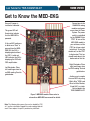
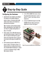
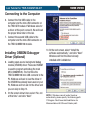
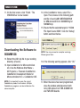
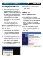
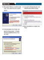
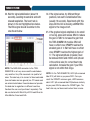
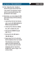
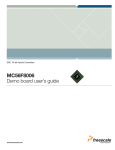
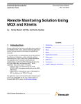
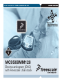
Lab Tutorial for TWR-S08MM128-KIT
LAB
1
MC9S08MM128
Electrocardiogram (EKG)
with Freescale USB stack
TOWER SYSTEM
TOWER SYSTEM
Introduction
This lab is a step-by-step guide to run
the EKG demo. The EKG demo uses
the S08MM128 on-chip analog modules
(TRIAMPs, OPAMPs, DAC and ADC)
along with noise filters to condition the
EKG signal. The EKG signal condition
includes the following stages:
1) Instrumentation amplification using on-chip
TRIAMP1, TRIAMP2 and OPAMP1
2) Band pass filtering
3) Amplification using on-chip OPAMP2
programmable gain
4) Notch filtering
5) Amplification using an off-chip OPAMP
6) Automatic baseline compensation
using on-chip 12-bit DAC
7) Digital filtering with the pre-programmed
MC56F8006 Freescale DSC
After digital filtering tuning, the end results
are sent from DSC via I2C protocol back
to S08MM128. The S08MM128 then uses
the Freescale USB stack to forward the
results to the computer, which are then
displayed on the Freescale MED-EKG
graphical user interface (GUI).
NOTE: The official marking for S08MM devices is MC9S08MM.
In this document, the MC9 prefix is omitted for simple
referencing.
NOTE: Please refer to the MED-EKG schematic for circuit
detail. The schematic is included in the DVD. Stages 6 and 7
may not be necessary in your own EKG application. They are
included in the MED-EKG to allow you to use off-chip devices
to help prototyping.
Required materials:
• TWR-S08MM128-KIT Quick Start Guide
• Tower System—Built according to
TWR-S08MM128-KIT Quick Start Guide
• MED-EKG module • Two mini-USB cables—One for TWRSER and one for TWR-S08MM128
• LAB1.zip—Located under the “Software”
tab, in the “Labs” section in the DVD.
Follow the lab guide for installation
• Computer installed with:
o CodeWarrior for Microcontrollers v6.3
oLatest S08MM128 service pack
oFreescale MED-EKG GUI (installation
file, MED_EKG_GUI.exe, included in
LAB1.zip)
oMicrosoft .NET Framework 2.0 or 3.5
(required to run MED-EKG GUI)
NOTE: This lab was tested with Windows® XP, Vista and
Windows 7.
Lab Tutorial for TWR-S08MM128-KIT
TOWER SYSTEM
Get to Know the MED-EKG
Ensure J2 jumper is
installed as indicated.
Connections to the
S08MM128 analog
modules and power
source from the Tower
System. The power
switch is controlled
by the S08MM128 pin
PTE7. To turn on the
MED-EKG module in
your software, set the
PTE7 pin to low output
(active low). To turn the
module off, set the PTE7
to high output. This has
already been done in the
demo code of this lab.
This green LED will
illuminate to indicate
that the MED-EKG is
powered.
If this red LED continues
to blink once “Start” is
pressed from the MEDEKG GUI, the GUI is
displaying data without
the DSC. A solid red
LED indicates the GUI is
displaying the EKG with
DSC amplification.
Right Electrodes: Place
right hand fingers here
for EKG reading. See lab
guide below.
Left Electrodes: Place
left hand fingers here for
an EKG reading. See lab
guide below.
Another way to sample
the user EKG is by using
“Welch Allyn® ECG Lead
Wires for Atlas Monitor,
3-lead AHA” or similar.
Not included in the
TWR-S08MM128-KIT.
Figure 1. MED-EKG module. Please refer to
schematic or MED-EKG user manual for details.
Note: The following lab assumes the user has loaded the DVD
at f:\ and has extracted all zipped files under working folder d:\
work. Please replace the path if your directory is different.
TOWER SYSTEM
LAB
1
Step-by-Step Guide
Configuring the Hardware
1. Assemble the Tower System and configure
the jumpers to the default settings as
shown in Step 2 of the Quick Start Guide
(QSG). Ensure that all of the boards are
pressed securely together.
Tip: It is easier to set the default jumpers
before assembling the Tower System. You
can follow the jumper settings shown in
Step 2 of the QSG.
2. Ensure jumper J16 on TWR-SER has pins 3
and 4 connected as shown in Figure 2 of the
QSG. This selects the USB port to support
device class transmission which is required
for printing the EKG signal to the MED-EKG
GUI.
3. Set the default jumpers for MED-EKG as
shown in Step 2 of the QSG or Figure 1 in
this lab. Note the J2 setting: there are two
silk-screened labels indicating pin 1 around
J2. Set J2 as indicated in Figure 1 MEDEKG module in this lab.
4. On the TWR-S08MM128 module, remove
the jumpers that connect pins 1 and 2, 9
and 10, 11 and 12, and 13 and 14 from
header J18.
5. Connect the MED-EKG board to the TWRS08MM128 board. Ensure that the pin
alignment is correct. See Figure 2.
Figure 2 Connecting the MED-EKG to the Tower System
Lab Tutorial for TWR-S08MM128-KIT
TOWER SYSTEM
Connecting to the Computer
6. Connect the first USB cable to the
computer and the mini-USB connector on
the TWR-SER module. If Windows asks for
a driver at this point, cancel it. We will load
the proper driver later in the lab.
7. Connect the second USB cable to the
computer and the mini-USB connector on
the TWR-S08MM128 module.
Installing OSBDM Debugger
Driver (Optional)
8. Loading open-source background debug
module (OSBDM) driver: Freescale OSBDM
is used to program and debug the main
MCU (S08MM128). The first time the
TWR-S08MM128 mini-USB connects to the
PC, Windows will ask to load the driver. If
the OSBDM has already been used on your
PC, Windows will not ask for the driver and
you can skip to Step 12.
9. On the screen shown here, select “No, not
at this time” and click “Next.”
10.At the next screen, select “Install the
software automatically,” and click “Next.”
Windows will find the driver already
installed with CodeWarrior.
NOTE: If Windows cannot locate the driver
automatically, please specify the following path:
C:\Program Files\Freescale\CodeWarrior for
Microcontrollers V6.3\Drivers\Osbdm-jm60
TOWER SYSTEM
11.On the final screen, click “Finish.” The
OSBDM driver is now loaded.
Downloading the Software to
S08MM128
12.Extract the LAB1.zip file to your working
directory (d:\work).
13.Open CodeWarrior for Microcontrollers
v6.3. Use the Windows Start Menu >
All Programs > Freescale CodeWarrior>
CodeWarrior Development Studio for
Microcontrollers V6.3 > CodeWarrior IDE.
NOTE: It is important to open the correct
CodeWarrior product and version. Multiple
CodeWarrior programs can be installed on the
same computer.
14.In the CodeWarrior menu, select File >
Open. Then, browse to the following path
and file: d:\work\LAB1\MEDEKGSW\SW
for MM devices\ECG for S08MM\Ecg for
S08MM.mcp
15.Ensure that the selected target is “HCS08
FSL Open Source BDM.” Click the “Debug”
button as shown below.
NOTE: You may encounter compiler warnings.
Please ignore them.
16.If the following warning appears, click “OK.”
17.When the device has been programmed,
close the window and disconnect both
mini-USB cables from TWR-S08MM128
and TWR-SER boards.
Lab Tutorial for TWR-S08MM128-KIT
Installing the MED EKG GUI
18.Microsoft .NET Framework 2.0 (support
up to Windows XP) or 3.5 (support up to
Windows 7) is required to run the MED-EKG
GUI. Please check if it is installed on your
computer by going to the “Add or Remove
Programs” feature from the Windows
Control Panel. If not, visit microsoft.com/
downloads/
Search for “.NET Framework” and
download the corresponding version.
NOTE: .Net 4.0 does not support the MED-EKG GUI.
If you have .NET 4.0 installed, you will still need to
install .NET 2.0 or 3.5.
19.Double click on file “MED_EKG_GUI.exe”
to start the GUI installation. It is located
in the folder d:\work\LAB1\MEDEKGSW\
MED_EKG_GUI.exe
20.In the installation popup windows, leave
the default settings and keep clicking the
“Next” button to start the installation.
21.During installation, the window below will
pop up. Click “OK” to continue.
TOWER SYSTEM
22.When installation is complete, click the
“Finish” button.
Installing the
Virtual Com Port Driver
23.Once the MED EKG GUI is installed,
reconnect the mini-USB cable to the TWRSER USB port. The “Found New Hardware
Wizard” will start to install the virtual
com USB CDC driver for the programmed
S08MM128.
24.At the “Found New Hardware Wizard”
screen, select “No, not at this time,” and
click “Next.”
TOWER SYSTEM
25.When asked “What do you want the wizard
to do?” click “Install from a list or specific
location.”
26.In the next window, click “Browse” and
select the following folder: c:\Program
Files\Freescale\MED-EKG\Driver\. Then,
click “Next.”
27.If you see the following dialog box, click
“Install this driver software anyway.”
28.When the installation is complete, click
“Finish.”
Lab Tutorial for TWR-S08MM128-KIT
TOWER SYSTEM
Running the MED-EKG DEMO
31.Select the COM port number found in Step
29. Then, click the “Start” button. You
will see the GUI start to display a random
waveform.
29.Once the CDC driver installation is
complete, find the exact COM port that
Windows assigned to the CDC device
in device manager. To access Device
Manager, right click the My Computer
icon from your Windows desktop, then
select “Manage.” Find the COM number as
indicated in the figure below.
NOTE: Program S08MM128 with LAB1 source code
and connect the USB to TWR-SER before opening the
GUI. Otherwise, close and reopen the GUI.
NOTE: COM10 is just an example. Each computer
may assign a different Virtual Com Port number.
30.Open the Graphical User Interface from
Start > All Programs > Freescale MED-EKG.
32.Remove rings from your fingers before
touching the electrodes as shown in the
images below.
TOWER SYSTEM
33.Wait for signal stabilization (about 10
seconds), avoiding movements and with
relaxed respiration. The heart rate is
shown in the red highlighted box below.
The EKG signal should be similar to the
one shown below.
NOTE: The MED-EKG connector to the TWRS08MM128 is not very secure and the electrode is
very sensitive. Very little movement can yield lot of
noise. The ideal way is to connect a three-lead cable
(two electrodes and one ground) via J12 header and
use external electrodes. Freescale does not provide
this lead due to regulations in different countries,
therefore the user must purchase it separately. This
lab was tested with Welch Allyn ECG Lead Wires for
Atlas Monitor, three-lead AHA.
34.If the signal varies, try different finger
positions, but wait for stabilization time
(usually 10 seconds). Experiment with this
step until the GUI is drawing a similar EKG
signal to the image at left.
35.If the graphed signal amplitude is too small
or too big, press and release SW4 to reduce
the gain or SW2 to increase the gain from
the TWR-S08MM128 module. SW4 will
have no effect once OPAMP2 reaches the
smallest gain of 2. SW2 will have no effect
once OPAMP2 reaches the highest gain of
17. The signal amplitude (in peaks) must
be between 8000 and 20000 units (shown
in the vertical axis) for correct heart rate
calculation. Increase the gain if your EKG
signal is not within that range.
NOTE: On the TWR-S08MM128, LED2 (silk-screened
label D10) will blink as you press SW2. Once you
reach the OPAMP2 maximum gain, LED2 becomes
solid. LED1 (silk-screened label D9) behaves similarly
as you press SW4 to reduce the OPAMP2 gain. The
heart rate may not be accurate when there is noise.
Lab Tutorial for TWR-S08MM128-KIT
36.If the “Display Raw Data” checkbox is
selected, the graph’s data will be shown
in the column on the right side. It may be
useful to copy and paste the data to the
spreadsheet for later analysis.
37.Alternatively, you can also display the EKG
signal without using the DSC by following
these steps:
• Open the Ecg.h file from the following
path: d:\work LAB1\MEDEKGSW\SW for
MM devices\app\ekg\Med-EKG
• In the Ecg.h file comment out #define
ECG_DSC to //#define ECG_DSC
• Reprogram the S08MM128 (repeat
step 13 to 17)
• Reconnect the mini-USB cable to
TWR-SER USB port
• Repeat steps 29 to 36. You will notice
the EKG amplitude will be much smaller.
This is because you are no longer
reading the results amplified by the
DSC. You will also notice the red LED
mentioned under the “Get to Know
the MED-EKG” section in Figure 1 will
continue to blink.
TOWER SYSTEM
TOWER SYSTEM
Information in this document is provided solely to enable system and software implementers to use Freescale Semiconductor
products. There are no express or implied copyright licenses granted hereunder to design or fabricate any integrated circuits or
integrated circuits based on the information in this document.
Freescale Semiconductor reserves the right to make changes without further notice to any products herein. Freescale
Semiconductor makes no warranty, representation, or guarantee regarding the suitability of its products for any particular
purpose, nor does Freescale Semiconductor assume any liability arising out of the application or use of any product or circuit, and
specifically disclaims any liability, including without limitation consequential or incidental damages. “Typical” parameters that may
be provided in Freescale Semiconductor data sheets and/or specifications can and do vary in different applications and actual
performance may vary over time. All operating parameters, including “Typicals,” must be validated for each customer application by
customer’s technical experts. Freescale Semiconductor does not convey any license under its patent rights nor the rights of others.
Freescale Semiconductor products are not designed, intended, or authorized for use as components in systems intended for
surgical implant into the body, or other applications intended to support or sustain life, or for any other application in which failure
of the Freescale Semiconductor product could create a situation where personal injury or death may occur. Should Buyer purchase
or use Freescale Semiconductor products for any such unintended or unauthorized application, Buyer shall indemnify Freescale
Semiconductor and its officers, employees, subsidiaries, affiliates, and distributors harmless against all claims, costs, damages, and
expenses, and reasonable attorney fees arising out of, directly or indirectly, any claim of personal injury or death associated with
such unintended or unauthorized use, even if such claims alleges that Freescale Semiconductor was negligent regarding the design
or manufacture of the part.
RoHS-compliant and/or Pb-free versions of Freescale products have the functionality and electrical characteristics as their
non-RoHS-complaint and/or non-Pb-free counterparts.
For further information, visit freescale.com or contact your Freescale sales representative.
For information on Freescale’s Environmental Products program, visit freescale.com/epp.
To learn more about the TWR-S08MM128-KIT and other Freescale medical products,
please visit freescale.com/s08mm, freescale.com/medical and freescale.com/tower.
Freescale, the Freescale logo and CodeWarrior are trademarks
of Freescale Semiconductor, Inc. Reg. U.S. Pat. & Tm. All other
product or service names are the property of their respective
owners. © 2010 Freescale Semiconductor, Inc.
Doc Number: S08MMMELAB1 / REV 0
Agile Number: 926-78433 / Rev A