1
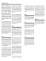
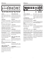
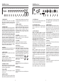
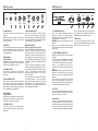
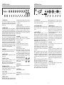
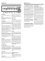
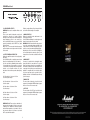
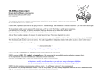
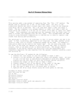
Congratulations on your purchase of this
all-valve, hand-wired amplifier – part of
Marshall’s revered Handwired Series.
Every head and combo in this expertly-crafted range has been designed, engineered
and constructed to the highest possible standards at the Marshall factory in the heart
of England. Based on original vintage Marshall amps produced in the ‘60s and early
‘70s, the Handwired Series has been created to be both sonically and visually as
authentic as possible. But why did Marshall founder, the late, great Jim Marshall
OBE, want to produce such a range?
The reason Jim decided to create the Handwired Series was simple – public demand.
One of the things Jim loved was meeting with and talking to guitarists at the many
trade shows, music fairs and shop appearances he attended all over the world. A
subject that almost always seemed to come up in conversation at such events was
hand-wiring. Jim realised that, even in this mass-produced digital age, there was still
a demand for authentically hand-crafted guitar amplifiers. The continuing success of
the Marshall Handwired Series is testament to Jim’s thinking.
In order to recreate the look, feel and tone of those much sought-after originals,
the Marshall team of designers have gone to enormous lengths to seek out and/
or reproduce all of the original components and materials, whilst also revisiting
the original methods of construction. From the hand-wired tag-board circuit to the
custom-manufactured Dagnall output and mains transformers, we are extremely
proud of the incredible accuracy and authenticity of these re-issued amplifiers.
We sincerely hope that this hand-wired piece of Marshall history will provide you with
countless hours of playing pleasure.
Yours Sincerely,
The Marshall Team
Follow all instructions and heed all warnings
KEEP THESE INSTRUCTIONS !
EUROPE ONLY - Note: This equipment has been tested and found to comply with the requirements of the EMC
Directive (Environments E1, E2 and E3 EN 55103-1/2) and the Low Voltage Directive in the E.U.
EUROPE ONLY - Note: The Peak Inrush current for the 1974X is 10 amps.
The Peak Inrush current for the 1958X is XX amps.
The Peak Inrush current for the 1973X is XX amps.
The Peak Inrush current for the 1962HW is 26 amps.
The Peak Inrush current for the 2061X is 11 amps.
The Peak Inrush current for the 2245THW is XX amps.
The Peak Inrush current for the 1959HW is 76 amps.
1
Handwired Series Overview
Our goal when designing the UK made
Handwired Series was both obvious and
simple: to make all the models in the range
as close to the originals as possible in terms
of components, circuitry, constructional
methods,
materials,
specifications,
aesthetics, signal path, performance, tonal
characteristics and feel. We’ve gone to
incredible lengths to achieve maximum
authenticity and are delighted to report that
our suppliers were equally as exacting in
their tasks.
Every model in the Handwired range possesses
it’s own unique tonal identity and yet they all share
a common sonic ‘DNA’. Namely those aggressive
yet sweetly distorted, harmonically rich, musical
tones resulting from perfectly crafted circuitry
and overdriven power valves. When ‘cranked’ the
amps and combos deliver pure vintage crunch and
become incredibly touch-sensitive, cleaning up or, if
desired, sitting right on the edge of distortion when
the guitar’s volume is turned down. Not surprisingly,
all the Handwired models respond extremely well to
picking dynamics, indefatigably ‘in-your-face’ when
you play like you really mean it and cleaning up as
you pull back on your picking attack.
The 1959HW is a Class-A/B, all-valve, 100 Watt, twochannel head. The circuit we have revisited for the
1959HW boasts several ‘tonally significant’ variants
when compared to the slightly later circuit we use for
our critically acclaimed, standard-production Plexi
re-issue - the 1959SLP. The most sonically relevant
technical departures in question lie in the negative
feedback circuit.
painstakingly revisited by our friends at Celestion
– right the way down to recreating the original
“Amplification by Marshall” gold label and also
painting the back of the magnet silver. The speakers
obviously play a vital sonic role as well as a cosmetic
one so Celestion’s meticulous nature is greatly
appreciated.
As you can see from its front panel layout, the
1959HW is an extremely straightforward amplifier. Its
two channels - Channel I and Channel II - each have
two inputs (High and Low sensitivity) and separate
Volume controls, while sharing the amplifier’s
four tone controls: Presence, Bass, Middle and
Treble. Like all Marshall, all-valve amplifiers, the
1959 sounds at its very best when turned up full and because of its conservative power rating and
astonishing projection, is a formidable live amplifier
in even the largest of venues.
2245THW
The 2245THW can be thought of as either the original
2245 with added tremolo (hence the ‘T’ in the model
name), or as a head version of the 1962HW. Either
way, all the features and components (minus the
speakers of course) are identical to the 1962HW.
1962HW
The 1962HW is an all-valve, 30 Watt, two channel,
2x12” combo and is a faithful recreation of the
legendary ‘Bluesbreaker’, harkening back to the
original format and circuit topology of the first
production run back in 1965. Both channels feature
high and low sensitivity inputs with separate Volume
controls and a shared an EQ section containing
Presence, Bass, Middle and Treble. The 1962HW’s
Tremolo circuit is governed by Speed and Intensity
controls.
1959HW
As is now rock folklore, the 1959 came to be when
The Who’s guitarist, Pete Townshend, approached
Marshall in the mid ’60s and asked Jim to build him
a ‘weapon’ that would allow him to play so loud that
he wouldn’t be able to hear what the members of the
audience were saying, should they have the sheer
audacity to talk whilst he was performing! Jim and
his team obliged and within weeks of Pete’s request
one of rock’s most instantly recognisable icons was
born - the 100 Watt Marshall stack.
Over the years the Tremolo circuit has been the main
target for many design improvements. However,
despite the Tremolo being reconfigured to give an
undoubtedly superior effect, its connection to the
signal path was also changed which, in turn, had a
sonic influence. For this tonal reason, we’ve reverted
back to the original valve Tremolo circuit as it’s
undeniably part of the 1962’s “mojo”.
The transformers are supplied by our long-time
partners at Drake who manufactured the originals all
those years ago. To add to the authenticity of these
all important components, the Drake engineers
used the original designs and worked meticulously
to duplicate the originals. Needless to say, with
the exception of a few necessary adjustments to
satisfy strict modern safety standards, the resulting
transformers are as close as humanly possible to the
originals.
The 1959 head first saw the light of day in late 1965
and was affectionately dubbed the Plexi because
of the material used for its front panel. Although we
continued to build 1959s, the now legendary Plexiera came to an end in July 1969 when we started
using gold anodised aluminium panels instead of
Plexiglas. While all original Plexi 1959s are held in
the highest esteem, several subtly different but
tonally significant circuit variations existed - the
most celebrated and revered versions being those
made between 1967 and 1969.
A definite contributing factor in the sound of the
vintage 1974 amplifiers is the way the Celestion
Greenback loudspeaker sound softens with age.
Celestion revisited the 1967 recipe for the original
20 Watt, ceramic magnet, 15 Ohm, Greenback
T1221 speaker used in the 1974 and supply it to
us exclusively. They meticulously duplicated every
critical vintage parameter from winding lengths, coil
former dimensions and edge treatment to using the
original dustcap material and adhesive. In sound
tests these speakers were close, but still lacked
something of the sonic signature of the originals.
1958X and 1973X
Both of these combos are variants of the 1974X; the
1958X features 2 x 10” Celestion aged Greenbacks
while the 1973X house the same quantity of
12” Celestion ‘Greenbacks’. All other features,
components and construction are identical to the
1974X.
2061X
The 2061X is an all-valve, 20 Watt, two-channel head
with no negative feedback in its cathode-biased
output stage. As you can see from its front panel
layout, the 2061X is an extremely straightforward
amplifier with both of its channels only boasting a
Volume and Tone control each.
Unlike its 18 Watt predecessors which boasted
an EZ81 rectifier, the 2061X features a solid-state,
silicon diode rectifying device, and is a much more
aggressive and surprisingly modern sounding
amplifier, while still possessing that unmistakable
and highly desirable, vintage all-valve tone.
1974X
The 1974X is an all-valve, 18 Watt, two-channel,
1x12” combo with valve driven tremolo and, just
like the 2061X, no negative feedback in its cathodebiased output stage. Channel 1 (the non-tremolo
channel) only boasts two, self-explanatory controls:
Volume and Tone; while Channel 2, the Tremolo
Channel, boasts four – namely Volume and Tone,
plus Speed and Intensity for the valve driven tremolo
circuit.
The 15 Ohm, G12 T652 Alnico magnet speakers
used in the original Series II model 1962 have been
2
3
1974X Front Panel
1
2
3
1974X Rear Panel
4
5
6
7
8
9
10
11
1. INDICATOR
This filament bulb indicator will light up when your
amplifier is switched on. It will not be lit when the
amplifier is switched off and/or is not receiving
mains power.
5. TREMOLO INTENSITY CONTROL
This controls the intensity or depth of the tremolo
oscillation when the effect is being used. The effect
depth increases when the Intensity control is turned
clockwise and decreases when it is turned
2. STANDBY SWITCH
The Standby Switch is used in conjunction with the
Power Switch (item 3) to ‘warm up’ the amplifier
before use and to prolong the life of the output
valves.
When powering up the amplifier always engage the
Power Switch first, leaving the Standby switch on
‘Standby’. This allows the application of the voltage
required to heat the valves to their correct operating
temperature – hence the switch’s name. After
approximately two minutes the valves will
have reached the correct operating temperature and
the Standby Switch can be engaged. Upon doing
this the H.T. (High Tension) voltage required by the
two EL84 output valves to pass signal (and hence
produce sound) is applied.
In order to prolong valve life, the Standby Switch
alone should also be used to turn the amplifier ‘on’
and ‘off’ during breaks in a performance. Also, upon
full power down, always disengage the Standby
Switch prior to the main Power Switch.
6. TONE CONTROL
This adjusts the tonal character of the Tremolo
Channel. Turning this control clockwise increases
the amount of high frequencies (treble) present in
the sound.
7. VOLUME CONTROL
This controls the volume of the Tremolo Channel.
Turning it clockwise increases the volume level of
the channel.
8. CHANNEL 2 INPUTS
These are the guitar inputs for the Tremolo Channel.
The top one is the ‘high sensitivity’ input for this
channel, the bottom one is the ‘low sensitivity’ input
which is 6dB lower (i.e. half) than the ‘high sensitivity’
input and has a darker sound. Always use a high
quality screened guitar lead.
CHANNEL 1 - THE NON-TREMOLO CHANNEL
9. TONE CONTROL
This controls the tonal character of Channel 1.
Turning the tone control clockwise increases the
amount of high frequencies (treble) present in the
sound.
3. POWER SWITCH
This is the On/Off switch for mains power to the
amplifier.
Note: Please ensure the amplifier is switched off
and unplugged from the mains electricity supply
whenever it is moved.
1
2
1. TREMOLO FOOTSWITCH JACK
This is where the supplied Tremolo on/off footswitch
is plugged in.
2. LOUDSPEAKER OUTPUTS
There are two parallel loudspeaker output jacks
provided for connection to the internal speaker and/
or an external load, i.e. speaker extension cabinet(s).
When connecting speaker(s) please always ensure
that the amplifier’s output impedance is set correctly
(item 3).
WARNING! Never use the combo without a load
attached! Always use a non-screened Marshall
approved speaker lead when connecting an
extension cabinet to these units.
5
6
4. MAINS FUSE
The correct value of mains fuse is specified on the
rear panel of the amplifier. NEVER attempt to bypass
the fuse or fit one of the incorrect value.
5. H.T. FUSE
The correct value of H.T. fuse is specified on the rear
panel of the amplifier. NEVER attempt to bypass the
fuse or fit one of the incorrect value.
3. OUTPUT IMPEDANCE SELECTOR
Matches the amplifier’s output to the load (speaker)
impedance.
As is the case with any Marshall all-valve amplifier
it is imperative that: a) the amplifier is connected
to a load whilst in operation and b) the impedance
selected on the amplifier matches the total
impedance of the internal speaker and/or extension
speaker cabinets.
The combo’s internal speaker is 15 Ohms so when
it is being used by itself the Impedance Selector
must be set to 16 Ohms. If an additional 16 Ohm
extension speaker cabinet is used in conjunction
with the internal speaker the Impedance Selector
should be set to 8 Ohms.
6. MAINS INPUT
Your amp is provided with a detachable mains
(power) lead, which is connected here. The specific
mains input voltage rating that your amplifier has
been built for is shown on the back panel. Before
connecting for the first time, please ensure that your
amplifier is compatible with your electricity supply.
If you have any doubt, please get advice from a
qualified technician. Your Marshall dealer will help
you in this respect.
11. CHANNEL 1 INPUTS
These are the guitar inputs for this Channel and both
are identical.
4
4
WARNING! An extension speaker cabinet with an
impedance of less than 16 Ohms should NOT be
used in conjunction with the internal speaker. The
amp should be completely powered down before
the Output Impedance Selector is turned. Failure to
comply with any of the points raised in this section
will result in damage to the amplifier.
10. VOLUME CONTROL
This controls the volume of Channel 1. Turning it
clockwise increases the volume level of the channel.
CHANNEL 2 - THE TREMOLO CHANNEL
4. TREMOLO SPEED CONTROL
This controls the speed of tremolo oscillation
when this effect (which can be switched on/off via
the supplied footswitch) is being used. Oscillation
speed increases when the Speed control is
turned clockwise and decreases when it is turned
anticlockwise.
3
5
1958X Front Panel
1
2
3
1958X Rear Panel
4
5
6
7
8
9
10
11
1. INDICATOR
This filament bulb indicator will light up when your
amplifier is switched on. It will not be lit when the
amplifier is switched off and/or is not receiving
mains power.
5. TREMOLO INTENSITY CONTROL
This controls the intensity or depth of the tremolo
oscillation when the effect is being used. The effect
depth increases when the Intensity control is turned
clockwise and decreases when it is turned
2. STANDBY SWITCH
The Standby Switch is used in conjunction with the
Power Switch (item 3) to ‘warm up’ the amplifier
before use and to prolong the life of the output
valves.
When powering up the amplifier always engage
the Power Switch first, leaving the Standby switch
on ‘Standby’. This allows the application of the
voltage required to heat the valves to their correct
operating temperature – hence the switch’s name.
After approximately two minutes the valves will have
reached the correct operating temperature and
the Standby Switch can be engaged. Upon doing
this the H.T. (High Tension) voltage required by the
two EL84 output valves to pass signal (and hence
produce sound) is applied.
In order to prolong valve life, the Standby Switch
alone should also be used to turn the amplifier ‘on’
and ‘off’ during breaks in a performance. Also, upon
full power down, always disengage the Standby
Switch prior to the main Power Switch.
6. TONE CONTROL
This adjusts the tonal character of the Tremolo
Channel. Turning this control clockwise increases
the amount of high frequencies (treble) present in
the sound.
7. VOLUME CONTROL
This controls the volume of the Tremolo Channel.
Turning it clockwise increases the volume level of
the channel.
8. CHANNEL 2 INPUTS
These are the guitar inputs for the Tremolo Channel.
The top one is the ‘high sensitivity’ input for this
channel, the bottom one is the ‘low sensitivity’ input
which is 6dB lower (i.e. half) than the ‘high sensitivity’
input and has a darker sound. Always use a high
quality screened guitar lead.
CHANNEL 1 - THE NON-TREMOLO CHANNEL
9. TONE CONTROL
This controls the tonal character of Channel 1.
Turning the tone control clockwise increases the
amount of high frequencies (treble) present in the
sound.
3. POWER SWITCH
This is the On/Off switch for mains power to the
amplifier.
Note: Please ensure the amplifier is switched off
and unplugged from the mains electricity supply
whenever it is moved.
1
2
1. TREMOLO FOOTSWITCH JACK
This is where the supplied Tremolo on/off footswitch
is plugged in.
2. LOUDSPEAKER OUTPUTS
There are two parallel loudspeaker output jacks
provided for connection to the internal speaker and/
or an external load, i.e. speaker extension cabinet(s).
When connecting speaker(s) please always ensure
that the amplifier’s output impedance is set correctly
(item 3).
WARNING! Never use the combo without a load
attached! Always use a non-screened Marshall
approved speaker lead when connecting an
extension cabinet to these units.
5
6
4. MAINS FUSE
The correct value of mains fuse is specified on the
rear panel of the amplifier. NEVER attempt to bypass
the fuse or fit one of the incorrect value.
5. H.T. FUSE
The correct value of H.T. fuse is specified on the rear
panel of the amplifier. NEVER attempt to bypass the
fuse or fit one of the incorrect value.
3. Output Selector
Matches the amplifier’s output to the load
impedance. With all-valve amplifiers it is imperative
that the amplifier is connected to a load whilst in
operation and that the impedance selected on the
amplifier matches the total impedance of the internal
speakers and/or extension speaker cabinets.
Important Note: Failure to do so will result in damge
to the amplifier. The two internal speakers are 16
Ohms each. These are wired in parallel giving an
overall impedance of 8 Ohms, therefore the output
selector should be set to 8 Ohms. If a 16 Ohm
extension speaker cabinet is used instead of the
internal speakers the output selector should be set
to 16 Ohms.
6. MAINS INPUT
Your amp is provided with a detachable mains
(power) lead, which is connected here. The specific
mains input voltage rating that your amplifier has
been built for is shown on the back panel. Before
connecting for the first time, please ensure that your
amplifier is compatible with your electricity supply.
If you have any doubt, please get advice from a
qualified technician. Your Marshall dealer will help
you in this respect.
11. CHANNEL 1 INPUTS
These are the guitar inputs for this Channel and both
are identical.
6
4
Note: No additional extension speaker cabinet
with an impedance lower than 8 Ohms should be
used. Failure to comply with these points will result
in damage to the amplifier. Your amp should be
completely powered down before the selector is
turned.
10. VOLUME CONTROL
This controls the volume of Channel 1. Turning it
clockwise increases the volume level of the channel.
CHANNEL 2 - THE TREMOLO CHANNEL
4. TREMOLO SPEED CONTROL
This controls the speed of tremolo oscillation
when this effect (which can be switched on/off via
the supplied footswitch) is being used. Oscillation
speed increases when the Speed control is
turned clockwise and decreases when it is turned
anticlockwise.
3
7
1973X Front Panel
1
2
3
1973X Rear Panel
4
5
6
7
8
9
10
11
1. INDICATOR
This filament bulb indicator will light up when your
amplifier is switched on. It will not be lit when the
amplifier is switched off and/or is not receiving
mains power.
5. TREMOLO INTENSITY CONTROL
This controls the intensity or depth of the tremolo
oscillation when the effect is being used. The effect
depth increases when the Intensity control is turned
clockwise and decreases when it is turned
2. STANDBY SWITCH
The Standby Switch is used in conjunction with the
Power Switch (item 3) to ‘warm up’ the amplifier
before use and to prolong the life of the output
valves.
When powering up the amplifier always engage
the Power Switch first, leaving the Standby switch
on ‘Standby’. This allows the application of the
voltage required to heat the valves to their correct
operating temperature – hence the switch’s name.
After approximately two minutes the valves will have
reached the correct operating temperature and
the Standby Switch can be engaged. Upon doing
this the H.T. (High Tension) voltage required by the
two EL84 output valves to pass signal (and hence
produce sound) is applied.
In order to prolong valve life, the Standby Switch
alone should also be used to turn the amplifier ‘on’
and ‘off’ during breaks in a performance. Also, upon
full power down, always disengage the Standby
Switch prior to the main Power Switch.
6. TONE CONTROL
This adjusts the tonal character of the Tremolo
Channel. Turning this control clockwise increases
the amount of high frequencies (treble) present in
the sound.
7. VOLUME CONTROL
This controls the volume of the Tremolo Channel.
Turning it clockwise increases the volume level of
the channel.
8. CHANNEL 2 INPUTS
These are the guitar inputs for the Tremolo Channel.
The top one is the ‘high sensitivity’ input for this
channel, the bottom one is the ‘low sensitivity’ input
which is 6dB lower (i.e. half) than the ‘high sensitivity’
input and has a darker sound. Always use a high
quality screened guitar lead.
CHANNEL 1 - THE NON-TREMOLO CHANNEL
9. TONE CONTROL
This controls the tonal character of Channel 1.
Turning the tone control clockwise increases the
amount of high frequencies (treble) present in the
sound.
3. POWER SWITCH
This is the On/Off switch for mains power to the
amplifier.
Note: Please ensure the amplifier is switched off
and unplugged from the mains electricity supply
whenever it is moved.
1
2
1. TREMOLO FOOTSWITCH JACK
This is where the supplied Tremolo on/off footswitch
is plugged in.
2. LOUDSPEAKER OUTPUTS
There are two parallel loudspeaker output jacks
provided for connection to the internal speaker and/
or an external load, i.e. speaker extension cabinet(s).
When connecting speaker(s) please always ensure
that the amplifier’s output impedance is set correctly
(item 3).
WARNING! Never use the combo without a load
attached! Always use a non-screened Marshall
approved speaker lead when connecting an
extension cabinet to these units.
5
6
4. MAINS FUSE
The correct value of mains fuse is specified on the
rear panel of the amplifier. NEVER attempt to bypass
the fuse or fit one of the incorrect value.
5. H.T. FUSE
The correct value of H.T. fuse is specified on the rear
panel of the amplifier. NEVER attempt to bypass the
fuse or fit one of the incorrect value.
3. Output Selector
Matches the amplifier’s output to the load
impedance. With all-valve amplifiers it is imperative
that the amplifier is connected to a load whilst in
operation and that the impedance selected on the
amplifier matches the total impedance of the internal
speakers and/or extension speaker cabinets.
Important Note: Failure to do so will result in damge
to the amplifier. The two internal speakers are 16
Ohms each. These are wired in parallel giving an
overall impedance of 8 Ohms, therefore the output
selector should be set to 8 Ohms. If a 16 Ohm
extension speaker cabinet is used instead of the
internal speakers the output selector should be set
to 16 Ohms.
6. MAINS INPUT
Your amp is provided with a detachable mains
(power) lead, which is connected here. The specific
mains input voltage rating that your amplifier has
been built for is shown on the back panel. Before
connecting for the first time, please ensure that your
amplifier is compatible with your electricity supply.
If you have any doubt, please get advice from a
qualified technician. Your Marshall dealer will help
you in this respect.
11. CHANNEL 1 INPUTS
These are the guitar inputs for this Channel and both
are identical.
8
4
Note: No additional extension speaker cabinet
with an impedance lower than 8 Ohms should be
used. Failure to comply with these points will result
in damage to the amplifier. Your amp should be
completely powered down before the selector is
turned.
10. VOLUME CONTROL
This controls the volume of Channel 1. Turning it
clockwise increases the volume level of the channel.
CHANNEL 2 - THE TREMOLO CHANNEL
4. TREMOLO SPEED CONTROL
This controls the speed of tremolo oscillation
when this effect (which can be switched on/off via
the supplied footswitch) is being used. Oscillation
speed increases when the Speed control is
turned clockwise and decreases when it is turned
anticlockwise.
3
9
1962HW Front Panel
MAINS
STANDBY
1962HW Rear Panel
SPEED
JTM
INTENSITY
4
6
0
10
2
ON
1
8
4
6
0
10
2
PRESENCE
8
4
6
0
10
2
BASS
8
MIDDLE
4
6
0
10
2
8
4
6
0
10
2
8
TREBLE
VOLUME I
VOLUME II
4
6
4
6
4
6
0
10
0
10
0
10
2
8
2
8
2
1
8
1
ON
2
2
INPUTS
FOOT PEDAL
2
Bar Code
PANL-00303 v1
1962HW 230V
3
4
5
6
7
1. Power Switch
On/Off Switch for mains power to the amplifier.
Please ensure the amplifier is switched off and
unplugged from the mains electricity supply before
being moved.
2. Standby Switch
The Standby Switch is used in conjunction with the
Power Switch to ‘warm up’ the amplifier before use
and to prolong the life of the output valves. When
powering up the amplifier always engage the Power
Switch first. This allows the application of the voltage
required to heat the valves to their correct operating
temperature. After about 2 minutes, when the valves
are up to the correct temperature, the Standby
Switch can be engaged. Upon doing this the H.T.
(High Tension) which is the high voltage required by
the output valves to pass signal (and hence produce
sound) is applied. To prolong valve life, the Standby
Switch alone should be used to turn the amplifier on
and off during breaks in a performance. Also, upon
full power down, always disengage the Standby
Switch prior to the main Power Switch.
8
9
10
11
12
13 14
15
4
230V - T500mAE250V
100V/120V - T500mAE250V
230V ~ 50Hz
175 Watts
230V - T1AE250V
100V/120V - T2AE250V
5
6
7
4. Mains Selector
Matches the amplifier mains transformer voltage to
the incoming mains voltage. Ensure that the rotary
Mains Selector is set to the correct mains voltage
applicable to the country where used. If you do
not know the mains input voltage contact your
authorised Marshall dealer.
Your amp should be completely powered down
before the selector is turned. Adjustment from 230v
to 120v to 100v or vice versa will require the mains
fuse to be changed to the corresponding value as
detailed on the rear panel.
3. Output Selector
Matches the amplifier’s output to the load
impedance. With all-valve amplifiers it is imperative
that the amplifier is connected to a load whilst in
operation and that the impedance selected on the
amplifier matches the total impedance of the internal
speakers and/or extension speaker cabinets.
Important Note: Failure to do so will result in damge
to the amplifier. The two internal speakers are 16
Ohms each. These are wired in parallel giving an
overall impedance of 8 Ohms, therefore the output
selector should be set to 8 Ohms. If a 16 Ohm
extension speaker cabinet is used instead of the
internal speakers the output selector should be set
to 16 Ohms.
Note: No additional extension speaker cabinet
with an impedance lower than 8 Ohms should be
used. Failure to comply with these points will result
in damage to the amplifier. Your amp should be
completely powered down before the selector is
turned.
Note: The electrical characteristics of the 1962HW’s
transformers are identical in every single aspect to
the original ones used back in 1965. The inclusion
of the 100V Line tap, while being historically correct,
is of little or no use on this particular model, if truth
be told. The reason it was present in the 60s was
because certain amps were able to drive multiple
remote 100V line speakers in various locations
5. H.T. Fuse
The correct value of H.T. fuse is specified on the rear
panel of the amplifier.
6. Mains Input
Your amp is provided with a detachable mains
(power) lead which is connected here. The specific
mains input voltage rating that your amplifier has
been built for is shown on the back panel. Before
connecting for the first time, please ensure that your
amplifier is compatible with your electricity supply.
If you have any doubt, please get advice from a
qualified person. Your Marshall dealer will help in
this respect.
7. Mains Fuse
The correct value of mains fuse is specified on the
rear panel of the amplifier.
15. Input Jack
Connects the guitar to the lower sensitivity input on
Channel 2.
8. Middle Control
Dictates the middle register of the amplifier. Turning
this up will make your guitar sound fatter. Conversely
10
3
MAINS FUSE
2. Loudspeaker Output
This is for connection to either the internal speakers
and/or an external load, i.e. speaker extension
cabinet.
14. Input Jack
Connects the guitar to Channel 2.
7. Bass Control
Controls the amount of low frequencies or bottom
end in your tone.
MAINS
MAINS INPUT
9. Treble Control
Controls the high frequencies of the guitar tone,
making your guitar sound brighter when increased.
Note: The tone network is highly interactive and
altering one control can change the shape of
the sound in relation to the other tone controls.
Experimentation is the best way to achieve your
desired sounds.
13. Input Jack
Connects the guitar to the lower sensitivity input on
Channel 1.
6. Presence Control
Adds higher frequencies to the guitar tone, creating
crispness and bite. Turning this up will make the
sound more cutting and ‘present’.
OUTPUT
H.T FUSE
within a particular venue. This option is effectively
the 1962HW’s appendix – an anatomically correct
but vestigial feature!
12. Input Jack
Connects the guitar to Channel 1.
Note: Though the first input of the first channel is
the input that most guitarists use, don’t be afraid
to experiment. Some guitar players prefer to mix
the two channels together by connecting a short,
screened patch lead between the second input of
Channel 1 and the first input of Channel 2. If you
then plug your guitar into the
2
first input of Channel 1 (item 12), 1
you can mix the different tonal
INPUTS
characters of each channel for 1
2
greater flexibility.
5. Intensity Control
Controls the intensity of oscillation (i.e. the effect
depth) when using the Tremolo effect.
Note: The tremolo effect will only work when playing
through Channel 2 of the 1962 combo.
2
SELECTOR
1. Footpedal Jack
For connection of the supplied footswitch to allow
Tremolo to be switched on and off.
11. Volume II
Controls the overall output level of Channel 2.
Note: Channel 2 is voiced for normal response.
4. Speed Control
Controls the speed of oscillation when using the
Tremolo effect.
CONNECT SPEAKERS BEFORE USE
OUTPUT: 30 WATTS RMS
SELECTOR
reducing the amount of middle in your tone will result
in a sharper and thinner guitar sound for a more
‘scooped’ tone.
10. Volume I
Controls the overall output level of Channel 1.
Note: This channel is voiced for a higher treble
response than Channel 2.
3. Indicator
The Indicator will be lit when your amplifier is on and
will not be lit when the amplifier is switched off.
1
SPEAKER
11
2061X Front Panel
1
2061X Rear Panel
2
3
4
5
6
7
8
1. POWER SWITCH
This is the On/Off switch for mains power to the
amplifier.
Note: Please ensure the amplifier is switched off
and unplugged from the mains electricity supply
whenever it is moved.
8. BASS CHANNEL INPUTS
These are the guitar inputs for the Bass Channel.
The top input is ‘high sensitivity’ and the bottom
input is ‘low sensitivity’, the latter being 6dB lower in
volume than the former with a darker sound. Always
use a high-quality, screened guitar cable.
2. INDICATOR
This 6.3 Volt incandescent filament indicator will light
up when your amplifier is switched on. It will not be
lit when the amplifier is switched off and/or is not
receiving mains power.
PERFORMANCE NOTE
Bridging or ‘jumping’ the two channels
Because both Channels of the 2061X have the same
number of gain stages (one) and are therefore in
phase with each other, it is possible to bridge them
together (a.k.a. ‘slaving’, ‘jumping’, ‘linking’ or even
‘daisy-chaining’) and use them both at the same
time, enabling you to expand upon the amps tonal
possibilities by mixing the Lead and Bass channels
together.
The most common way of doing this is to plug your
guitar into the top (high sensitivity) input of one of the
two channels and then run a short ‘jumper’ guitar
cable (i.e. a screened cable) from that channel’s
bottom (low sensitivity) input to one of the other
channel’s two inputs.
It is also possible to plug your guitar into the bottom
(low sensitivity) input of one of the two channels
and then run the ‘jumper’ cable from its top (high
sensitivity) input to one of the other channel’s two
inputs. This less-common approach can also yield
some interesting tonal variations.
LEAD CHANNEL
3. TONE CONTROL
This adjusts the tonal character of the Lead Channel.
Turning this control clockwise increases the amount
of high frequencies (treble) in the sound.
4. VOLUME CONTROL
This controls the volume of the Lead Channel.
Turning it clockwise increases the volume level of
the channel.
5. LEAD CHANNEL INPUTS
These are the guitar inputs for the Lead Channel.
The top input is ‘high sensitivity’ and the bottom
input is ‘low sensitivity’, the latter being 6dB lower in
volume than the former with a darker sound. Always
use a high-quality, screened guitar lead.
BASS CHANNEL
6. TONE CONTROL
This adjusts the tonal character of the Bass Channel.
Turning this control clockwise increases the amount
of high frequencies (treble) in the sound.
1
2
1. LOUDSPEAKER OUTPUTS
There are two parallel loudspeaker output jacks
provided for connection to speaker extension
cabinet(s). Please always ensure that the amplifier’s
output impedance is set correctly .
WARNING! Never use the head without a load
attached!
Always use a non-screened Marshall approved
speaker lead when connecting an extension cabinet
to these units.
12
4
5
with your electricity supply. If you have any doubt,
please get advice from a qualified technician. Your
Marshall dealer will help you in this respect.
5. MAINS FUSE
The correct value of mains fuse is specified on the
rear panel of the amplifier. NEVER attempt to bypass
the fuse or fit one of the incorrect value.
2. OUTPUT IMPEDANCE SELECTOR
Matches the amplifier’s output to the load (speaker)
impedance.
As is the case with any Marshall all-valve amplifier
it is imperative that: a) the amplifier is connected
to a load whilst in operation and b) the impedance
selected on the amplifier matches the total
impedance of the extension speaker cabinets being
used.
WARNING! An extension speaker cabinet with an
impedance of less than 4 Ohms, or two extension
cabinets of 4 Ohms or less should NOT be used with
this head.
The amp should be completely powered down
before the Output Impedance Selector is turned.
Failure to comply with any of the points raised in this
section will result in damage to the amplifier.
3. H.T. FUSE
The correct value of H.T. fuse is specified on the rear
panel of the amplifier. NEVER attempt to bypass the
fuse or fit one of the incorrect value.
4. MAINS INPUT
Your amp is provided with a detachable mains
(power) lead, which is connected here. The specific
mains input voltage rating of your amplifier is shown
on the back panel. Before connecting for the first
time, please ensure that your amplifier is compatible
7. VOLUME CONTROL
This controls the volume of the Bass Channel.
Turning it clockwise increases the volume level of
the channel.
3
13
2245THW Front Panel
MAINS
STANDBY
SPEED
JTM
INTENSITY
4
6
0
10
2
ON
1
2245THW Rear Panel
8
4
6
0
10
2
PRESENCE
8
4
6
0
10
2
BASS
8
MIDDLE
4
6
0
10
2
8
4
6
0
10
2
8
TREBLE
VOLUME I
VOLUME II
4
6
4
6
4
6
0
10
0
10
0
10
2
8
2
8
2
1
8
1
ON
2
2
INPUTS
FOOT PEDAL
2
Bar Code
PANL-00303 v1
2245THW 230V
3
4
5
6
7
1. Power Switch
On/Off Switch for mains power to the amplifier.
Please ensure the amplifier is switched off and
unplugged from the mains electricity supply before
being moved.
2. Standby Switch
The Standby Switch is used in conjunction with the
Power Switch to ‘warm up’ the amplifier before use
and to prolong the life of the output valves. When
powering up the amplifier always engage the Power
Switch first. This allows the application of the voltage
required to heat the valves to their correct operating
temperature. After about 2 minutes, when the valves
are up to the correct temperature, the Standby
Switch can be engaged. Upon doing this the H.T.
(High Tension) which is the high voltage required by
the output valves to pass signal (and hence produce
sound) is applied. To prolong valve life, the Standby
Switch alone should be used to turn the amplifier on
and off during breaks in a performance. Also, upon
full power down, always disengage the Standby
Switch prior to the main Power Switch.
8
9
10
11
12
13 14
15
4
230V - T500mAE250V
100V/120V - T500mAE250V
230V ~ 50Hz
175 Watts
230V - T1AE250V
100V/120V - T2AE250V
5
6
7
4. Mains Selector
Matches the amplifier mains transformer voltage to
the incoming mains voltage. Ensure that the rotary
Mains Selector is set to the correct mains voltage
applicable to the country where used. If you do
not know the mains input voltage contact your
authorised Marshall dealer.
Your amp should be completely powered down
before the selector is turned. Adjustment from 230v
to 120v to 100v or vice versa will require the mains
fuse to be changed to the corresponding value as
detailed on the rear panel.
3. Output Selector
Matches the amplifier’s output to the load
impedance. With all-valve amplifiers it is imperative
that the amplifier is connected to a load whilst in
operation and that the impedance selected on the
amplifier matches the total impedance of the internal
speakers and/or extension speaker cabinets.
Important Note: Failure to do so will result in damge
to the amplifier. The two internal speakers are 16
Ohms each. These are wired in parallel giving an
overall impedance of 8 Ohms, therefore the output
selector should be set to 8 Ohms. If a 16 Ohm
extension speaker cabinet is used instead of the
internal speakers the output selector should be set
to 16 Ohms.
Note: No additional extension speaker cabinet
with an impedance lower than 8 Ohms should be
used. Failure to comply with these points will result
in damage to the amplifier. Your amp should be
completely powered down before the selector is
turned.
Note: The electrical characteristics of the 2245THW’s
transformers are identical in every single aspect to
the original ones used back in 1965. The inclusion
of the 100V Line tap, while being historically correct,
is of little or no use on this particular model, if truth
be told. The reason it was present in the 60s was
because certain amps were able to drive multiple
remote 100V line speakers in various locations
5. H.T. Fuse
The correct value of H.T. fuse is specified on the rear
panel of the amplifier.
6. Mains Input
Your amp is provided with a detachable mains
(power) lead which is connected here. The specific
mains input voltage rating that your amplifier has
been built for is shown on the back panel. Before
connecting for the first time, please ensure that your
amplifier is compatible with your electricity supply.
If you have any doubt, please get advice from a
qualified person. Your Marshall dealer will help in
this respect.
7. Mains Fuse
The correct value of mains fuse is specified on the
rear panel of the amplifier.
15. Input Jack
Connects the guitar to the lower sensitivity input on
Channel 2.
8. Middle Control
Dictates the middle register of the amplifier. Turning
this up will make your guitar sound fatter. Conversely
14
3
MAINS FUSE
2. Loudspeaker Output
This is for connection to either the internal speakers
and/or an external load, i.e. speaker extension
cabinet.
14. Input Jack
Connects the guitar to Channel 2.
7. Bass Control
Controls the amount of low frequencies or bottom
end in your tone.
MAINS
MAINS INPUT
9. Treble Control
Controls the high frequencies of the guitar tone,
making your guitar sound brighter when increased.
Note: The tone network is highly interactive and
altering one control can change the shape of
the sound in relation to the other tone controls.
Experimentation is the best way to achieve your
desired sounds.
13. Input Jack
Connects the guitar to the lower sensitivity input on
Channel 1.
6. Presence Control
Adds higher frequencies to the guitar tone, creating
crispness and bite. Turning this up will make the
sound more cutting and ‘present’.
OUTPUT
H.T FUSE
within a particular venue. This option is effectively
the 2245THW’s appendix – an anatomically correct
but vestigial feature!
12. Input Jack
Connects the guitar to Channel 1.
Note: Though the first input of the first channel is
the input that most guitarists use, don’t be afraid
to experiment. Some guitar players prefer to mix
the two channels together by connecting a short,
screened patch lead between the second input of
Channel 1 and the first input of Channel 2. If you
then plug your guitar into the
2
first input of Channel 1 (item 12), 1
you can mix the different tonal
INPUTS
characters of each channel for 1
2
greater flexibility.
5. Intensity Control
Controls the intensity of oscillation (i.e. the effect
depth) when using the Tremolo effect.
Note: The tremolo effect will only work when playing
through Channel 2 of the 2245THW head.
2
SELECTOR
1. Footpedal Jack
For connection of the supplied footswitch to allow
Tremolo to be switched on and off.
11. Volume II
Controls the overall output level of Channel 2.
Note: Channel 2 is voiced for normal response.
4. Speed Control
Controls the speed of oscillation when using the
Tremolo effect.
CONNECT SPEAKERS BEFORE USE
OUTPUT: 30 WATTS RMS
SELECTOR
reducing the amount of middle in your tone will result
in a sharper and thinner guitar sound for a more
‘scooped’ tone.
10. Volume I
Controls the overall output level of Channel 1.
Note: This channel is voiced for a higher treble
response than Channel 2.
3. Indicator
The Indicator will be lit when your amplifier is on and
will not be lit when the amplifier is switched off.
1
SPEAKER
15
1959HW Front Panel
1
2
3
1959HW Front Panel cont.
4
5
6
1. POWER SWITCH
This is the On/Off switch for mains power to the
amplifier.
Note: Please ensure the amplifier is switched off
and unplugged from the mains electricity supply
whenever it is moved.
7
8
9
10
11 12
13
frequencies. Turning it clockwise increases the
mids and fattens your sound, giving it more punch.
Turning it anticlockwise reduces the mids, producing
a more ‘scooped’ tone.
7. TREBLE CONTROL
This adjusts the top-end. Turning it clockwise
increases the amount of high frequencies (treble)
present in the sound, making your guitar tone
brighter.
Note: The following four controls - PRESENCE (item
4), BASS (item 5), MIDDLE (item 6) & TREBLE (item
7) - are all shared, meaning that they all work on both
Channel I and Channel II. They are highly interactive
and altering one control can change the way the
other two behave. For this reason, experimentation
is recommended.
2. STANDBY SWITCH
The Standby Switch is used in conjunction with the
Power Switch (item 1) to ‘warm up’ the amplifier
before use and to prolong the life of the output
valves.
When powering up the amplifier always engage the
Power Switch first, leaving the Standby switch on
‘Standby’. This allows the application of the voltage
required to heat the valves to their correct operating
temperature - hence the switches name.
After approximately two minutes the valves will have
reached the correct operating temperature and the
Standby Switch can be engaged.
In order to prolong valve life, the Standby Switch
alone should also be used to turn the amplifier on
and off during breaks in a performance. Also, when
switching off, always disengage the Standby Switch
prior to the main Power Switch.
11. LOW SENSITIVITY INPUT FOR CHANNEL I
This is the ‘low sensitivity’ guitar input for Channel
I. It is 6dB lower in volume than the ‘high sensitivity’
input and has a darker sound as well due to its
significantly lower input impedance.
Interesting aside: Back in the day, a ‘high sensitivity’
input jack was recommended for use with a guitar
loaded with low-output pickups (e.g: single coils)
while the ‘low sensitivity’ input was recommended
for higher output pickups (e.g: humbuckers). This
said, the majority of guitarists - then and now - ignore
these recommendations and plug high-output
guitars into the ‘high sensitivity’ input because it
further boosts the strength of their signal.
Performance Note:
Bridging or ‘jumping’ the two channels
Because both Channels of the 1959HW have the
same number of gain stages (two) and are therefore
in phase with each other, it is possible to bridge
them together (‘slaving’, ‘jumping’, ‘linking’ or even
‘daisychaining’) and use them both at the same
time. Doing this enables you to expand upon the
amp’s tonal possibilities by mixing the two channels
together.
The most common way of doing this is to plug your
guitar into the top (high sensitivity) input of Channel
I and then run a short ‘jumper’ guitar cable (i.e. a
screened cable) from the Channel I’s bottom (low
sensitivity) input to the top (high sensitivity) input of
Channel II. (fig. 1)
The ‘reverse’ is also possible – namely plugging your
guitar into Channel II’s top input and then running
the ‘jumper’ cable from Channel II’s bottom input to
Channel I’s top input. This less common approach
can yield some interesting tonal variations. (fig. 2)
12. HIGH SENSITIVITY INPUT FOR CHANNEL II
This is the ‘high sensitivity’ guitar input for Channel II,
the so-called ‘Normal’ channel.
13. LOW SENSITIVITY INPUT FOR CHANNEL I
This is the ‘low sensitivity’ guitar input for Channel
II. It is 6dB lower in volume than the ‘high sensitivity’
input and has a darker sound as well due to its
significantly lower input impedance.
8. VOLUME I
This controls the overall output level of Channel I,
turning it clockwise increases the volume. This
channel is voiced for a higher treble response than
Channel II.
Tonal Note 5: The value of the capacitor across
Volume I is 0.005μF. This rather large value makes
this channel aggressive and bright at relatively
low settings. Many players bridge (see page 6 for
details) Channels I and II (which has a darker, less
aggressive tone) in order to have more control over
their overall tone. Many earlier versions of the 1959
(from 1965 to 1967) used a 100pf capacitor across
Volume I which gives a less aggressive sound at all
volume levels less than 8.
3. INDICATOR
This 6.3 Volts incandescent filament indicator will
light up when your amplifier is receiving the correct
mains power and is switched on. It will not be
lit when the amplifier is switched off and/or is not
receiving mains power.
4. PRESENCE CONTROL
This control operates in the 1959HW’s power section
and adds high frequencies to your sound by altering
the power amplifier’s negative feedback. Turning this
control clockwise adds more edge and ‘sparkle’ to
your sound, making it crisper and more cutting.
9. VOLUME II
This controls the overall output level of Channel II,
turning it clockwise increases the volume level. This
channel is voiced for a ‘normal’, flatter response and
is labelled as the ‘Normal’ Channel in later versions
of the 1959.
5. BASS CONTROL
This adjusts the bottom end, turning it clockwise
increases the amount of low frequencies in the
sound.
10. HIGH SENSITIVITY INPUT FOR
CHANNEL I
This is the ‘high sensitivity’ guitar input for Channel
I - the brighter of the two channels - and is the most
commonly used input. Always use a high quality
screened guitar lead.
6. MIDDLE CONTROL
This adjusts the level of those all-important midrange
16
17
1959HW Rear Panel
1
1. LOUDSPEAKER OUTPUTS
WARNING! Never use the amplifier without a load
attached!
There are two parallel loudspeaker output jacks
provided for connection to speaker extension
cabinet(s). Please always ensure that the amplifier’s
output impedance selector is set correctly (see
item 2) and ALWAYS ensure you use good quality
speaker (unshielded) cables. NEVER use guitar
(shielded) cables.
Always use a non-screened Marshall approved
speaker lead when connecting an extension cabinet
to these units.
2
3
4
5
6
Failure to comply with any of the points raised in this
section will result in damage to the amplifier.
3. MAINS SELECTOR
Matches the amplifier’s mains transformer to the
incoming mains voltage.
Your 1959HW should always be completely powered
down before the mains selector is turned.
WARNING! ALWAYS ensure that this rotary selector
is set to the correct mains voltage applicable for the
country where the 1959HW is being used. If you do
not know, consult your authorized Marshall dealer.
Adjusting the selector from 230V to 120/100V or
vice-versa will require the mains fuse (item 5) to be
changed to the correct value as detailed on the rear
panel.
2. OUTPUT IMPEDANCE SELECTOR
Matches the amplifier’s output to the load (speaker)
impedance.
Your 1959HW should be completely powered down
before the Output Impedance Selector is turned.
As is the case with any Marshall all-valve amplifier
it is imperative that: a) the amplifier is connected
to a load whilst in operation and b) the impedance
selected on the amplifier matches the total
impedance of the extension speaker cabinet(s being
used.
4. MAINS INPUT
Your amp is provided with a detachable mains
(power) lead, which is connected here. The specific
mains input voltage rating that your amplifier has
been built for is indicated on the back panel. Before
connecting for the first time, please ensure that your
amplifier is compatible with your electricity supply.
If you have any doubt, please get advice from a
qualified technician. Your Marshall dealer will help
you in this respect.
1x16 Ohm cabinet - Selector on 16 Ohm
Use either speaker output
5. MAINS FUSE
The correct value of mains fuse is specified on the
rear panel of the amplifier. NEVER attempt to bypass
the fuse or fit one of the incorrect value.
2x16 Ohm cabinets - Selector on 8 Ohm
Use both outputs
1x8 Ohm cabinet - Selector on 8 Ohm
Use either output
6. H.T. FUSE
The correct value of this H.T. fuse is specified on the
rear panel of the amplifier. NEVER attempt to bypass
the fuse or fit one of the incorrect value.
2x8 Ohm cabinets - Selector on 4 Ohm
Use both outputs
1x4 Ohm cabinet - Selector on 4 Ohm
Use either output
WARNING! Do NOT use any other combination of
cabinets and/or impedances. Doing so may result
in damage to the amplifier! An extension speaker
cabinet with an impedance of less than 4 Ohms, or
two extension cabinets of 4 Ohms or less should
NOT be used with this amplifier.
18
19