1
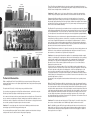
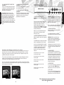
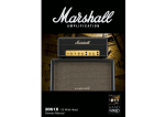
Overview: Historical, Tone and Tech Talk
From the Chairman
Congratulations on your purchase of this handwired
re-issue of a model 1959 100 Watt, all-valve, Super
Lead head. The original versions of this world famous
amplifier - nicknamed the ‘Plexi’ because of its front
panel material - were produced from late 1965 to mid
1969 and are now extremely rare and highly collectable.
This authentic reiteration of an SL/A head made pre-July
of 1969 is part of an ongoing series, which will feature handwired re-issues of revered historical
Marshall products. The reason I have decided to do this is simple - public demand!
One of the things I love doing most is meeting and talking to Marshall users at the many trade
shows, music fairs and shop appearances I do all over the world every year. A subject that almost
always seems to come up in conversation at such events is hand-wiring. In fact, in recent years so
many people have asked me to please start building handwired re-issue products that I’ve lost count!
Not surprisingly, given its much discussed tonal legacy and impressive list of groundbreaking, worldfamous users, the most frequently requested vintage Marshall amps to appear in such a guise is an
early version of the model 1959 Plexi head you've just bought - hence its inclusion as one of our first
handwired re-issues.
Just like its well-known vintage predecessor, the JTM45, the 1959HW is relatively simple in terms of
controls, features and circuitry, but sounds and feels fantastic. To recreate the incredible tone and
feel of the original, as well as its eye-catching good looks, my team of designers has gone to
enormous lengths to seek out and reproduce all of the original components and materials plus revisit
the original methods of construction we used back in the mid 1960s. From the handwired tag-board
circuits to the custom-manufactured Dagnall output and mains transformers, I am extremely proud of
the incredible accuracy and authenticity of this re-issue.
I sincerely hope that this handwired landmark of Marshall history will provide you with countless
hours of playing pleasure.
Yours Sincerely,
The 1959HW is a Class-A/B, all-valve, 100 Watt, two-channel
head. When building this handwired re-issue of an amazing
sounding, original Plexi head made in 1969, our goal was both
obvious and simple: to make it as close to the original as
possible in terms of components, circuitry, constructional
methods, materials, specifications, aesthetics, signal path,
performance, tonal characteristics and feel. We went to
incredible lengths to achieve maximum authenticity and are
delighted to report that our suppliers were equally as exacting
in their tasks - none-more-so than our long-time partner,
Dagnall Transformers.
As is now rock folklore, the 1959 came to be when The Who’s
guitarist, Pete Townshend, approached Marshall in the mid
’60s and asked Jim to build him a ‘weapon’ that would allow
him to play so loud that he wouldn’t be able to hear what the
members of the audience were saying, should they have the
sheer audacity to talk whilst he was performing! Jim and his
team obliged and within weeks of Pete’s request one of rock’s
most instantly recognisable icons was born - the 100 Watt
Marshall stack.
As Jim Marshall has already stated, the 1959 head first saw
the light of day in late 1965 and was affectionately dubbed the
Plexi because of the material used for its front panel. Although
we continued to build 1959s, the now legendary Plexi-era
came to an end in July 1969 when we started using gold
anodised aluminium panels instead of Plexiglas. While all
original Plexi 1959s are held in the highest esteem, several
subtly different but tonally significant circuit variations existed the most celebrated and revered versions being those made between 1967 and 1969.
The circuit we have revisited for the 1959HW boasts several of said ‘tonally significant’ variants when
compared to the slightly later circuit we use for our critically acclaimed, standard-production Plexi re-issue the 1959SLP. The most sonically relevant technical departures in question lie in the negative feedback
circuit. Where relevant, specific details concerning these ‘deviations’, and others, are inserted into the text
labelled as ‘Tonal Notes’.
As you can see from its front panel layout, the 1959HW is an extremely straightforward amplifier. Its two
channels - Channel I and Channel II - each have two inputs (High and Low sensitivity) and separate Volume
controls, while sharing the amplifier’s four tone controls: Presence, Bass, Middle and Treble. Like all
Marshall, all-valve amplifiers, the 1959 sounds at its very best when turned up full - and because of its
conservative power rating and astonishing projection, is a formidable live amplifier in even the largest of
venues. A truth its impressive history has proven time-and-time again, from the mid ’60s to current day.
In keeping with its other non-master-volume, all-valve, Marshall brethren such as the JTM45 head and the
1962 ‘Bluesbreaker’ combo, the 1959HW's aggressive yet sweetly distorted, harmonically rich, thick,
musical tones result from its power valves being overdriven. As a result, when ‘cranked’ the 1959HW’s
instantly recognisable, guttural, ‘punch you in the chest’ roar is incredibly touch-sensitive, cleaning up or, if
desired, sitting right on the edge of distortion when the guitar's volume is turned down. Not surprisingly, it
responds well to picking dynamics too, indefatigably ‘in-your-face’ when you play like you really mean it and,
once again, cleaning up as you pull back on your picking attack.
1
ENGLISH
ENGLISH
Introduction
OUTPUT
TRANSFORMER
MAINS
TRANSFORMER
Tone Circuit: In typical Marshall fashion, the shared tone network of this handwired 1959 re-issue is
post gain, passive and interactive - the latter simply meaning that the settings of the Bass and Treble controls
affect the amount of mid-dip available via the Middle control.
Tonal Note 2: The Middle control is a 10% log pot, unlike the linear one found in the regular production
1959SLP. This greatly changes the dynamic of the whole tonal network and the interaction of its controls.
CHOKE
Components: Where possible we have gone back to the original suppliers for all components, to
ENGLISH
Tag Boards: The tag boards used in your handwired re-issue is exactly the same as that in the original in
terms of thickness and matrix pitch. The material we're using is made exclusively for us and is registered with
UL as ‘Marshall EM42 brown’. The reason we didn’t use a board with the exact same chemical composition
as in the original units is because that material doesn't pass current safety legislation regarding flammability.
Transformers: As you are no doubt aware, the output and mains transformers are vital components in
an amplifier as they influence performance, sound and feel. Consequently, we worked extremely closely with
our associates in Dagnall’s R&D department in order to duplicate the original transformers. To do this we
spent a great deal of time and attention studying and analysing the constructional methods and materials
used in both transformers so we could match everything as closely as possible and also ensure that the allimportant electrical characteristics and performance were identical.
EL34 POWER
VALVES
SINGLE CUSTOM-BUILT
50µF CAPACITOR
ECC83 VALVES
V1
V2
V3
Technical Information
Output Transformer: Just like the 1.5" original, it is an exact replica in terms of both performance and
dimensions, the re-issue transformer is upright-mounting and sits entirely above the chassis. To be exact,
this transformer is a C1998 which has a specification date of August 1967
Tonal Note 3: In the vast majority of Marshall valve amplifiers it is a standard design trait that the negative
feedback (a circuit that drops the output impedance and thus controls the damping factor of the powerstage)
applied around the amplifier is taken from the 8 Ohm tap on the output transformer. Doing this sets the
power-amp up for a certain amount of damping that is independent of where you have the amplifier's
impedance selector set. This means that, regardless of whether you use a 16, 8 or 4 Ohm cabinet, the
damping on the speakers is the same.
This said, as is the case with quite a number of ‘Plexi’ era 100 Watt heads, the negative feedback on the
original 1969 circuit we've used for this reissue is taken off the actual speaker output itself. This means that
the lower the impedance setting, the lower the damping factor - and the lower the damping factor is, the
more loose and more resonant the sound. Consequently, if you’re using a 4 x 12" cabinet loaded with
16 Ohm speakers that offers 16 Ohm and 4 Ohm mono inputs (e.g.: the Marshall 1960A, 1960B, 1960AV or
1960BV cabinets), the 4 Ohm input will be more loose and more resonant on the low end, while the 16 Ohm
input will be tighter and more controlled.
Not surprisingly, of the ‘tonally significant’ variants mentioned in this manual, this one is probably the most
significant.
Valve compliment: Three ECC83s (12AX7s) in the pre-amp and a quartet of EL34 power valves
working in push-pull. All valves are of the highest quality available and are subjected to meticulous grading
and testing processes.
The way the three ECC83s (V1, V2 & V3) in the pre-amp are utilised is as follows:
V1 acts as the pre-amp gain stage for the High Treble and Normal channels - each half of the valve (the
ECC83 being a dual-triode) acting as a dedicated gain stage for each channel.
V2 is common to both channels, which are passively summed before reaching this valve. The first half of V2
acts as a common second gain stage, boosting the combined signal, and then directly driving the second
half of the valve which is configured as a cathode follower. The cathode follower is a unity gain device which
acts as a buffer, providing a low impedance signal to drive the tone network.
Tonal Note 1: The second gain stage of the 1969 circuit we’ve faithfully reproduced boasts an extra
cathode bypass capacitor which boosts upper-mids and top-end.
V3 acts as the amplifier's phase-splitter. This device divides the signal into two halves that are 180 degree
out-of-phase with each other, and then feed the 1959's push-pull output stage.
2
Mains (Power) Transformer: While the original transformer is large, the custom-made Dagnall reissue has been made even larger in order to satisfy strict, current-day safety legislation. Just like the original,
the re-issue transformer is what is called a ‘drop through, half-shroud’, which sits horizontally as opposed to
vertically. As with the output transformer, we went to great lengths to ensure that its performance mirrors that
of the original, paying particular attention to exactly replicating an effect called ‘regulation’ - which is the way
that the voltage from the transformer that feeds the valve circuitry varies according to load. In terms of the
concentric design and performance, this transformer embodies the performance of the 1203-80 original
specification first drawn up for us by Drake in February 1967. The original was a 2.5" transformer. Due to the
aforementioned modern legislations, the reissue is 3".
Tonal Note 4: This circuit has the same filtering on the H.T. (high voltage DC, a.k.a. the B+ voltage) line as
later versions, a factor that contributes to the 1959HW having a tighter sound than earlier versions.
Note: The 1959HW incorporates 47nF/630V capacitors fitted in parallel with each of the four diodes in the
bridge rectifier circuit. These are present for today’s approval requirements that necessitate a reduction in
electrical interference that may be generated and put back on the mains electricity supply. The addition of
these capacitors has no sonic impact.
3
ENGLISH
maintain the highest quality - including, as per the original, a U-clamp mounted choke as opposed to the
fully-shrouded, stand-up smoothing choke used in the majority of Marshall valve amplifiers. Also included is a
custom-built 50µF single can, smoothing capacitor. These are just two examples of the many steps we have
taken in order to ensure maximum authenticity.
Chassis: We are using a box-section chassis made from 16 gauge mild steel with butt-welded corner
10
12
11
13
1959HW Front Panel
Front Panel: Extra thick, gold coloured Plexiglas (actually Perspex, causing some people to refer to it
as ‘Perplexi!’) - exactly as the original. Specific details pertaining to the front panel features can be found on
page 5 of this manual.
1
2
3
4
5
Rear Panel: Once again, gold Plexiglas - just like the original we referenced.
1. POWER SWITCH
Cabinet Construction: High-grade, flawless (knot-free) Baltic birch-ply with fingerlocked joints for
This is the On/Off switch for mains power to the
amplifier.
maximum strength. The main cabinet frame (both sides, top and bottom) are 15mm ply, the front baffle is
constructed from 12mm ply while the back of the cabinet is 9mm ply. All edges have a 15mm radius.
Cabinet Cosmetics: The 6" gold Marshall logo, black Levant covering, beading and piping model the
look and style of the original.
6
7
8
9
the mids and fattens your sound, giving it more
punch. Turning it anticlockwise reduces the mids,
producing a more ‘scooped’ tone.
7. TREBLE CONTROL
Note: Please ensure the amplifier is switched off
and unplugged from the mains electricity supply
whenever it is moved.
This adjusts the top-end. Turning it clockwise
increases the amount of high frequencies (treble)
present in the sound, making your guitar tone
brighter.
2. STANDBY SWITCH
The Standby Switch is used in conjunction with the
Power Switch (item 1) to ‘warm up’ the amplifier
before use and to prolong the life of the output
valves.
When powering up the amplifier always engage the
Power Switch first, leaving the Standby switch on
‘Standby’. This allows the application of the voltage
required to heat the valves to their correct
operating temperature - hence the switches name.
After approximately two minutes the valves will
have reached the correct operating temperature
and the Standby Switch can be engaged.
In order to prolong valve life, the Standby Switch
alone should also be used to turn the amplifier on
and off during breaks in a performance. Also, when
switching off, always disengage the Standby Switch
prior to the main Power Switch.
Note: The following four controls - PRESENCE
(item 4), BASS (item 5), MIDDLE (item 6) &
TREBLE (item 7) - are all shared, meaning that
they all work on both Channel I and Channel II.
They are highly interactive and altering one control
can change the way the other two behave. For this
reason, experimentation is recommended.
8. VOLUME I
This controls the overall output level of Channel I,
turning it clockwise increases the volume. This
channel is voiced for a higher treble response than
Channel II.
Tonal Note 5: The value of the capacitor across
Volume I is 0.005µF. This rather large value makes
this channel aggressive and bright at relatively low
settings. Many players bridge (see page 6 for
details) Channels I and II (which has a darker, less
aggressive tone) in order to have more control over
their overall tone. Many earlier versions of the 1959
(from 1965 to 1967) used a 100pf capacitor across
Volume I which gives a less aggressive sound at all
volume levels less than 8.
3. INDICATOR
This 6.3 Volts incandescent filament indicator will
light up when your amplifier is receiving the correct
mains power and is switched on. It will not be lit
when the amplifier is switched off and/or is not
receiving mains power.
4. PRESENCE CONTROL
Technical Specification
Power Output
Weight
Size
EUROPE ONLY
100W RMS
21.4 kg
740mm x 270mm x 210mm
- Note: This equipment has been tested and found to comply with the
This control operates in the 1959HW’s power
section and adds high frequencies to your sound
by altering the power amplifier’s negative feedback.
Turning this control clockwise adds more edge and
‘sparkle’ to your sound, making it crisper and more
cutting.
9. VOLUME II
5. BASS CONTROL
10. HIGH SENSITIVITY INPUT FOR
CHANNEL I
requirements of the EMC Directive (Environments E1, E2 and E3 EN 55103-1/2) and the Low Voltage
Directive in the E.U.
This adjusts the bottom end, turning it clockwise
increases the amount of low frequencies in the
sound.
EUROPE ONLY - Note: The Peak Inrush current for the 1959HW is 76 amps.
6. MIDDLE CONTROL
This controls the overall output level of Channel II,
turning it clockwise increases the volume level.
This channel is voiced for a ‘normal’, flatter
response and is labelled as the ‘Normal’ Channel in
later versions of the 1959.
This is the ‘high sensitivity’ guitar input for Channel I
- the brighter of the two channels - and is the most
commonly used input. Always use a high quality
screened guitar lead.
This adjusts the level of those all-important midrange frequencies. Turning it clockwise increases
4
5
ENGLISH
ENGLISH
joints. The steel is also passivated giving lifelong resistance to corrosion.
Our original chassis has a lot of extra holes drilled in it that weren't used. No doubt these existed because
the same exact chassis was also used for other products made at the time. The most noticeable ‘extra hole’
is one on top for a fourth ECC83 and on our reference unit, this particular hole has been covered up with a
disc of steel that's been riveted into the two screw holes that would have been used to secure the valve
holder, were it there. For the sake of authenticity we have copied all the holes on our reference chassis and
have even duplicated the aforementioned circular steel cover!
12. HIGH SENSITIVITY INPUT FOR
CHANNEL II
This is the ‘low sensitivity’ guitar input for Channel I.
It is 6dB lower in volume than the ‘high sensitivity’
input and has a darker sound as well due to its
significantly lower input impedance.
This is the ‘high sensitivity’ guitar input for Channel II,
the so-called ‘Normal’ channel.
Interesting aside: Back in the day, a ‘high
sensitivity’ input jack was recommended for use
with a guitar loaded with low-output pickups (e.g.:
single coils) while the ‘low sensitivity’ input was
recommended for higher output pickups (e.g.:
humbuckers). This said, the majority of guitarists then and now - ignore these recommendations and
plug high-output guitars into the ‘high sensitivity’
input because it further boosts the strength of their
signal.
This is the ‘low sensitivity’ guitar input for Channel II.
It is 6dB lower in volume than the ‘high sensitivity’
input and has a darker sound as well due to its
significantly lower input impedance.
1959HW Rear Panel
13. LOW SENSITIVITY INPUT FOR
CHANNEL I
1
2
3
4
5
6
WARNING! Do NOT use any other combination of
cabinets and/or impedances. Doing so may result
in damage to the amplifier! An extension speaker
cabinet with an impedance of less than 4 Ohms, or
two extension cabinets of 4 Ohms or less should
NOT be used with this amplifier.
1. LOUDSPEAKER OUTPUTS
WARNING! Never use the amplifier without a load
attached!
There are two parallel loudspeaker output jacks
provided for connection to speaker extension
cabinet(s). Please always ensure that the
amplifier's output impedance selector is set
correctly (see item 2) and ALWAYS ensure you use
good quality speaker (unshielded) cables. NEVER
use guitar (shielded) cables.
Failure to comply with any of the points raised in
this section will result in damage to the amplifier.
3. MAINS SELECTOR
Matches the amplifier’s mains transformer to the
incoming mains voltage.
Always use a non-screened Marshall approved
speaker lead when connecting an extension
cabinet to these units.
Your 1959HW should always be completely
powered down before the mains selector is turned.
2. OUTPUT IMPEDANCE SELECTOR
WARNING! ALWAYS ensure that this rotary
selector is set to the correct mains voltage
applicable for the country where the 1959HW is
being used. If you do not know, consult your
authorized Marshall dealer.
Matches the amplifier’s output to the load (speaker)
impedance.
Your 1959HW should be completely powered down
before the Output Impedance Selector is turned.
Performance Note: Bridging or ‘jumping’ the two channels
Because both Channels of the 1959HW have the same number of gain stages (two) and are therefore in
phase with each other, it is possible to bridge them together (‘slaving’, ‘jumping’, ‘linking’ or even ‘daisychaining’) and use them both at the same time. Doing this enables you to expand upon the amp’s tonal
possibilities by mixing the two channels together.
The most common way of doing this is to plug your guitar into the top (high sensitivity) input of Channel I
and then run a short ‘jumper’ guitar cable (i.e. a screened cable) from the Channel I’s bottom (low
sensitivity) input to the top (high sensitivity) input of Channel II. (fig. 1)
The ‘reverse’ is also possible – namely plugging your guitar into Channel II’s top input and then running the
‘jumper’ cable from Channel II’s bottom input to Channel I’s top input. This less common approach can yield
some interesting tonal variations. (fig. 2)
Adjusting the selector from 230V to 120/100V or
vice-versa will require the mains fuse (item 5) to be
changed to the correct value as detailed on the
rear panel.
As is the case with any Marshall all-valve amplifier
it is imperative that: a) the amplifier is connected to
a load whilst in operation and b) the impedance
selected on the amplifier matches the total
impedance of the extension speaker cabinet(s)
being used.
4. MAINS INPUT
Your amp is provided with a detachable mains
(power) lead, which is connected here. The specific
mains input voltage rating that your amplifier has
been built for is indicated on the back panel. Before
connecting for the first time, please ensure that
your amplifier is compatible with your electricity
supply. If you have any doubt, please get advice
from a qualified technician. Your Marshall dealer
will help you in this respect.
1x16 Ohm cabinet - Selector on 16 Ohm
Use either speaker output
2x16 Ohm cabinets - Selector on 8 Ohm
Use both outputs
1x8 Ohm cabinet - Selector on 8 Ohm
Use either output
5. MAINS FUSE
2x8 Ohm cabinets - Selector on 4 Ohm
Use both outputs
The correct value of mains fuse is specified on the
rear panel of the amplifier. NEVER attempt to
bypass the fuse or fit one of the incorrect value.
1x4 Ohm cabinet - Selector on 4 Ohm
Use either output
6. H.T. FUSE
The correct value of this H.T. fuse is specified on
the rear panel of the amplifier. NEVER attempt to
bypass the fuse or fit one of the incorrect value.
Fig. 1
Fig. 2
Follow all instructions and heed all warnings
KEEP THESE INSTRUCTIONS !
6
7
ENGLISH
ENGLISH
11. LOW SENSITIVITY INPUT FOR
CHANNEL I