1
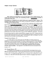
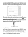
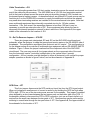
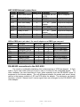
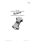
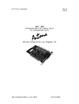
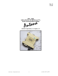
Rev. C
$ 5.00
ANC - 6085
RS-485/422 Serial Communications Adapter
Antona Corporation, Los Angeles, CA
Antona Corporation
(818 )783-4299
i
Antona Corporation
Copyright
Copyright (c) 2002-2003 by Antona Corporation. All rights reserved. No part of this
publication may be reproduced, transmitted, transcribed, stored in a retrieval system, or
translated into any language or computer language, in any form or by any means, electronic,
mechanical, magnetic, optical, chemical, manual or otherwise, without the prior written
permission of the Antona Corporation of Los Angeles, California.
Warranty
Antona Corporation products are warranted to be free from defects in materials and
workmanship for a period of one (1) year from the date of original shipment to customer.
This warranty is limited to the replacement or repair of parts not subjected to misuse,
neglect, unauthorized repair, alteration (except card options), accident, or failure due to the
effects of static electricity discharge.
In no event shall Antona Corporation be liable to the purchaser for loss of use, profit, or
consequential damages, or damages of any kind, including, but not limited to, accidental loss or
damage to other equipment, arising out of use of Antona Corporation equipment, whether or not
said equipment was used properly. The designer is responsible for the determining the
suitability and use of the product.
This warranty is in lieu of any other warranty, expressed, implied, or statutory, including,
without limitation, any implied warranty or merchantability or fitness for a particular purpose. No
amendment of this warranty may be effected except in writing by an officer of the Antona
Corporation.
ALL REPAIR SERVICES SHALL BE PERFORMED AT THE ANTONA CORPORATION PLANT IN
LOS ANGELES, CA.
THE PURCHASER MUST OBTAIN A RETURN
AUTHORIZATION FROM THE ANTONA CORPORATION PRIOR TO
RETURNING ANY PIECE OF EQUIPMENT.
SHIPMENT TO THE ANTONA
CORPORATION WILL BE AT THE EXPENSE OF THE PURCHASER, RETURN SHIPMENT WILL BE AT
THE EXPENSE OF THE ANTONA CORPORATION FOR ALL WARRANTY REPAIRS.
Antona Corporation
(818 )783-4299
1
TABLE OF CONTENTS
FEATURES
3
OVERVIEW
3
MECHANICAL SPECIFICATIONS
ELECTRICAL SPECIFICATIONS
ADAPTER INSTALLATION
SERIAL PORT POWERING
EXTERNAL POWERING
3
3
4
4
4
ADAPTER JUMPER OPTIONS
5
Figure 1 - ANC-6085 jumper locations
TRANSMIT CONTROL ENABLE - JP1
AUTO TRANSMIT SOURCE - JP2
Photo 1 – Auto Transmit Operation
figure 2 – RTS low to Tx enable
RECEIVE ENABLE - JP3
CABLE TERMINATION - JP4
TX - RX PIN REVERSE JUMPERS – JP5/JP6
figure 3 – Tx/Rc Pin Reverse Jumpers
DCD DRIVE – JP7
5
5
5
6
6
6
7
7
7
7
ANC-6085 EXTERNAL CONNECTIONS
8
DB9 TO DB25 PIN TO PIN CHART - FOR USE OF ADAPTER ON A DB25 TYPE COM PORT
8
RS-485/422 CONNECTIONS TO THE ANC-6085
8
DB9 RS-485/422 SIGNALS FOR MASTER (MULTIMEDIA CONTROLLER)
DB9 RS-485/422 SIGNALS FOR SERVER (RECEIVE FROM MASTER)
9
9
RS-485 TWO AND FOUR WIRE INTERFACING
9
2-WIRE
figure 4 – typical 2-wire RS-485 interface
Photo 2 – 2-wire interface example
4-WIRE
9
10
10
10
APPENDIX A – TROUBLESHOOTING GUIDE
11
LOOPBACK TEST
CABLING (MOST COMMON PROBLEM)
PIN SIGNAL DEFINITION (4-WIRE INTERFACES)
MULTIDROP CABLING (2-WIRE INTERFACES)
DATA DIRECTION JUMPERS
SIGNAL CONTROL JUMPERS
CABLE TERMINATION
POWERING
PROGRAM OPERATION
RS422/485 EQUIPMENT
PLUGGED IN BACKWARDS
NOW WHAT?
11
11
11
11
12
12
12
12
13
13
13
13
APPENDIX B -CIRCUIT BOARD SCHEMATIC
14
Antona Corporation
(818 )783-4299
2
Features
Auto-transmit (AutoXmit) enable is available at baud rates up to 64 KBPS.
Transmit data at distances up to 4000 feet (1219.2 m)
Baud rates to 1 Mbaud
Powered from serial port for most installations
4 wire full duplex or 2 wire half duplex operation
Operate in multidrop / multipoint applications (RS-485)
Jumperable terminate (120 ohms) on input
Selectable data loopback feature or data echo suppression (in 2-wire applications)
Choice of fixed, auto or RTS high controlled transmit
Latest surface mount technology (SMT) for low power and small size
Plug compatible with DB-9 Pc RS-232C serial ports
Pin connections on converted RS-485/422 signal side mate directly to many professional
multimedia units (SMPTE interface for Sony, BTS, Grass Valley, Ampex, etc.)
Overview
The ANC-6085 adapter converts the serial port RS-232C level transmit and receive
signals on an IBM compatible personal computer (Pc), or any device with an RS-232C type
interface, into bipolar-current RS-485 or RS-422 compatible signals. The adapter interface
voltage levels produced meet the EIA-232, TIA-232, RS-485 and RS-485/422 signals. These
adapters find wide use in high-speed long distance serial communications, multidropped 2-wire
interfaces or to interface a Pc with equipment that uses an RS-485 or RS-485/422 type
input/output. The adapter is powered by the host system’s signal lines the same way a serial
port “mouse” interface is powered. For most installations this eliminates the need for an
external power supply making the adapters an ideal choice for portable use. Extended cable
runs and/or terminated RS-485/422 connections may require more current than the serial port
power can provide so the RS-485/422 connector can accept +3v to +12v regulated DC at 100
milliamps to provide the added power to drive the adapter.
Mechanical Specifications
Adapter case size: 2.2" X 1.2"
Connectors:
Female DB9 to Pc
Female DB9 to RS-485/422 equipment
Electrical Specifications
Power requirements = 6 ma for short cable, non-terminated applications
100 ma for long and/or terminated cable applications
RS-485/422 output drive= short proof output, non-terminated operation to 150 feet,
terminated operation with external power supply to 4000 feet.
RS232 output drive=short proof output, under worse case conditions, ±5v switching
to exceed ±3v EIA RS232 specification
Antona Corporation
(818 )783-4299
3
Adapter Installation
Turn off the personal computer and any other remote equipment before performing the
adapter installation. Never install or remove the adapter with the power applied to the Pc
or any of the attached equipment. This could result in permanent damage to the adapter
due to static discharge.
Normally the adapter is plugged directly into the serial port male DB-9 jack on the back of
the Pc. Be sure to look at the label on the adapter to identify and insure that the proper
DB9 is plugged into the Pc’s serial jack. The ANC-6085 has female DB9s at both ends. The
user should screw the 2 mounting screws into the serial port’s hex nuts for permanent
installations to assure good long-term connection.
The adapter may be attached to a ribbon cable type extension from the Pc to the Antona
adapter. This is sometimes useful when the space is limited behind the Pc. The ribbon cable
extension should not exceed 3 feet. A 12’ shielded wire cable could also be used. Remember
that the signal is still RS-232C level leaving the computer and entering the adapter. Also note
that if the designer is using a DB9 to DB25 adapter an A-B selector box or break-out box for
testing, that all 9 pins should be connected through the adapter or test setup. The main ANC6085 adapter power is drawn from the host system’s RTS and DTR lines, like a mouse
interface.
Serial Port Powering
Three of the Pc’s serial port RS-232C level signals can be used by the Antona adapter to
derive power from: RTS, DTR and TX. The user must therefore insure that the RTS and DTR
signals from the Pc’s serial port are brought to a high output level 100 ms before communicating
over the adapter. Usually this is performed once during the user’s program initialization. When
the appropriate jumper is set, RTS is lowered and raised to receive and transmit respectively for
use in 2-wire interfaces.
External Powering
An external DC power source may be feed into pin 9 on the RS-485/422 DB-9 connector to
supply the additional current that the adapter may need. The table “RS-485/422 Connections to
the ANC-6085” (page 9) shows the pins for using an external source of DC to power the
adapter. There are also two pads on the ANC-6085 circuit board you can solder leads to for
applying external power. A small hole in the plastic case would need to be added to run the
power supply leads away from the adapter. Figure 1 below shows the pad as black dots. The
+3v to +12v regulated DC is soldered to the pin located just to the right of JP7, and the power
supply ground pin is soldered to the pad just above JP4.
Antona Corporation
(818 )783-4299
4
Adapter Jumper Options
Figure 1 - ANC-6085 jumper locations
When shipped, the ANC-6085 is set for transmit and receive enabled always. The
output pins are set for ‘master’, the terminating resister is disconnected and RTS is
connected to DCD (JP7).
All references to ‘horizontal’ and ‘vertical’ below are in respect to figure 1 above. The
schematic gives another view of each jumper showing the settings on isolated block
drawings of each jumper function.
To open the enclosure hood use a small flat blade screwdriver and carefully pry the
plastic latches on one side of the enclosure and gently separate the sides slightly (about .020”).
Place a paper clip or coin between the separated sides of the enclosure to keep it from relatching shut while you repeat the process on the two plastic latches on the other side of the
hood. The two sides of the hood should now come apart. The computer side mounting screws
are loose within the enclosure so be careful of these small parts. To reassemble the enclosure
hood back around the adapter electronics, place the circuit board into the enclosure half that
designates signal direction with the RS-485/422 connector (the DB-9 connector that has the
jackscrews) on the arrowed end pointed to by the small “RS485/422” designation. Now place
the small screws back into position on the RS232, or computer side, DB-9. Double check that
the hood labeled with which end is RS-232 and RS-485/422 is properly oriented before closing
the sides and relatching all four plastic holds. The RS-485/422 end of the adapter is the end
with the jack nuts mounted onto the female DB-9 connector.
Transmit Control Enable - JP1
For single adapter 4-wire setups where the ANC-6085 is controlling one piece of
equipment, JP1 can be set in the horizontal position, as shipped, so that the transmit data RS485/422 driver lines are always asserted. For battery powered applications, it may be desirable
to turn off the transmit drivers to save current when there is no data being transmitted. When
using either the transmit data control or RTS signal control to automatically control driver
output, the vertical position should be set and JP2 (below) should be set for the desired
transmit control condition. See Appendix B, the middle left hand of the schematic for the
location of JP1.
Auto Transmit Source - JP2
The designer can automatically turn on the RS-485/422 transmit driver lines by using
either the transmitted data itself (JP2 set to the vertical position) or the RTS line (as shipped,
JP2 set to the horizontal position). See Appendix B, the lower left hand of the schematic for the
location of JP2. As shipped the ANC-6085 is set for one character time at 9600 baud, or about
1 millisecond. When the TX RS-232C data line starts to transmit by toggling a logic ‘high’ on
Antona Corporation
(818 )783-4299
5
the serial port producing the raising edge of the ‘start’ bit, circuitry on the ANC-6085 will detect
and turn on the transmit RS-485/422. The photo below shows how a RS-232 character being
transmitted (top trace) triggers the transmit driver enable line (lower trace) to perform the auto
transmit function. There are actually two 9600 baud characters superimposed to show how the
transmit enable line always allows about 1ms from the falling edge of the last bit.
Photo 1 – Auto Transmit Operation
RTS may also be used to turn on/off the transmit driver lines. Normally when RTS is used,
asserting the signal ‘high’ to the adapter enables transmitting. This makes sense because more
current is used from the RTS line during transmit in self powered applications. If your
application software requires RTS to be low on transmit, you can use a wire jumper either wirewrapped to the top side of the circuit board or a short piece of wire soldered to the bottom side
of the circuit board to select RTS enable transmit ‘low’ and set RS-485/422 drive output as
pictured in figure 2 below. Note that DTR must be set high when RTS is low in order for the
adapter to operate when an external power supply is not being used.
figure 2 – RTS low to Tx enable
Receive Enable - JP3
This 3-pin straight vertical jumper can be set to enable receiving RS-485/422 data
always (as shipped, JP3 set on the lower and middle pin), or turned off automatically whenever
the transmit driver is active which is set by JP1 and JP2 above (JP3 set on the middle and
upper pin. See Appendix B, the middle left hand of the schematic for the location of JP3. On a
2-wire interface if data is being transmitted and the receiver is also enabled, anything
transmitted will be ‘looped-back’ into the serial port. Since the echoed signal is the actual data
that was transferred to the interface cable, being able to see the transmitted data echoed back
may be of use for testing, authenticating or diagnostics of data output.
Antona Corporation
(818 )783-4299
6
Cable Termination - JP4
For site lengths greater than 150 feet, resister termination across the remote receive pair
end of the cable may be necessary. The ANC-6085 has a ½W 120 ohm termination resister
built in that can be placed across the receive wire pair by setting jumper 4 (JP4) located over
the transmit/receive setting jumpers. As described above, an external DC power source may be
feed into pin 9 on the RS-485/422 connector to supply the additional current that the adapter
may need when terminating resisters are installed on the receive/transmit wire pairs. Note that
some multimedia equipment have internally connected circuitry for 120 ohm resister
termination. If So, then even if the separation distance is less than 150 feet, it may be
necessary to provide an external source of DC. Some equipment also allows the user to
disconnect the internal termination network for short cable runs. See Appendix B, the upper
middle of the schematic for the location of JP4.
Tx - Rx Pin Reverse Jumpers – JP5/JP6
These two jumper sets, designated JP5 and JP6 on the ANC-6085 circuit board and
schematic, allow the designer to swap the transmit and receive pairs on the RS-485/422 side of
the adapter. The configuration as shipped from Antona is set for ‘master’. This configuration is
for the adapter acting as a controller to multimedia type equipment with an RS-485/422 SMPTE
interface. Figure 1 shows the jumper locations from the component side of the ANC-6085
circuit board. The user may move all four jumper shunts on the component side of the card
from the horizontal ‘master’ (controller) configuration to the vertical ‘slave’ (remote)
configuration. All four jumpers must be changed to either all horizontal or all vertical for proper
adapter operation as shown in figure 3 below, and on the schematic of Appendix B.
figure 3 – Tx/Rc Pin Reverse Jumpers
DCD Drive – JP7
This 2-pin jumper disconnects the DCD serial port input line from the RTS signal output.
When not jumpered a small amount of current is saved by not holding the DCD line high when
RTS is high. RTS is one of the two main power sources for the adapter. This jumper is enabled
when shipped by a short trace between the two jumper pads on the solder side of the PCB. If
the designer wishes to disconnect the RTS to DCD connection, just use an Exacto knife to cut
and remove the small trace between the two pads of JP7. Reconnection may be performed by
soldering in a small wire through the two pad holes of JP7. See Appendix B, the upper middle of
the schematic for the location of JP7.
Antona Corporation
(818 )783-4299
7
ANC-6085 External connections
Signal
DCD/R
LSD
RX
TX
DTR
GND
DSR
RTS
CTS
RI
Function
DB-9 Pin # Comment
Data Carrier Detect
1
Connected via JP7
to RTS
RECEIVE DATA
2
RS-232 level input
TRANSMIT DATA
3
RS-232 level output
Data Term Ready
4
+v
to
power
adapter
GROUND
5
Signal ground
Data Set Ready
6
Tied to DTR (pin 4)
Ready to Send
7
+v
to
power
adapter
Clear to Send
8
Tied to RTS (pin 7)
Ring Indicator
9
Not connected
Data Direction
input to computer
input to computer
output from computer
output from computer
I/O signal ground
input to computer
output from computer
input to computer
input to computer
DB9 to DB25 pin to pin chart - for use of adapter on a DB25 type com port
Signal
DCD/RLSD
RX
TX
DTR
GND
DSR
RTS
CTS
RI
Function
Data Carrier Detect
RECEIVE DATA
TRANSMIT DATA
Data Term Ready
GROUND
Data Set Ready
Ready to Send
Clear to Send
Ring Indicator
DB-9 Pin #
1
2
3
4
5
6
7
8
9
DB-25 Pin
8
3
2
20
7
6
4
5
22
Comment
RS-232 level input
RS-232 level output
+v to power adapter
signal ground
tied to DTR (pin 4)
+v to power adapter
RS-485/422 connections to the ANC-6085
For normal or multimedia interfacing, this is the jumpering of JP5/6 as shipped. A 9-pin
male to 9-pin male cable wired pin-to-pin is used to connect to the multimedia device. For
other interfaces, the user hand-wires a 9-pin cable assembly from the RS-485/422 piece of
equipment to the Antona adapter. The only difference between the master and server (slave)
version is the jumper positions of JP5 and JP6 within the adapter. The electronics are exactly
the same, only the 2 transmit and 2 receive signal lines are exchanged on the RS-485/422 side
of the adapter.
Antona Corporation
(818 )783-4299
8
DB9 RS-485/422 Signals for Master (Multimedia Controller)
DB9 CONN (J2) FUNCTION
1
GROUND
2
3
4
5
6
7
8
9
RCTX+
GROUND
RC+
TX+V
IDENTIFICATION
ground for RS-485/422 and/or external
power (same function as pin 5)
RS-485/422 minus side input
RS-485/422 plus side output
-not usedground for RS-485/422 and/or external
power (same function as pin 1)
-not usedRS-485/422 plus side input
RS-485/422 minus side output
Optional +3V to +12V DC @ 100ma
DB9 RS-485/422 Signals for Server (Receive from Master)
DB9 CONN (J2) FUNCTION
1
GROUND
2
3
4
5
TXRC+
GROUND
6
7
8
9
TX+
RC+V
IDENTIFICATION
ground for RS-485/422 and/or external
power (same function as pin 5)
RS-485/422 minus side output
RS-485/422 plus side input
-not usedground for RS-485/422 and/or external
power (same function as pin 1)
-not usedRS-485/422 plus side output
RS-485/422 minus side input
Optional +3V to +12V DC @ 100ma
RS-485 Two and Four Wire Interfacing
2-wire
One of the key features of using a controlled transmit adapter like the ANC-6085 is for
applications using multidrop 2-wire interfacing with other RS-485 type equipment. Usually a two wire
interface with multiple peripherals uses a ‘polled-response’ half-duplex software protocol where each
device has a unique device code. Generally, this requires externally powering of the adapter, but for
short cable runs to non-terminated equipment operating at medium baud rates (like 9600 or less) an
external power supply may not be needed. The designer should use twisted pair wire witha impedance
of 100 to 120 ohms. Plain old low-cost CAT-5 UTP (Unshielded Twisted Pair) wire works fine. The user
must externally wire the cable with pin 3 connected to pin 7 (TX+ to RC+) and pin 8 to pin 2 (TX- to RC-)
on the RS-485 connector side of the adapter. The 2 conductor cable which connects to the outside
world is then wired to pin 7 (+DATA) and to pin 2 (-DATA) of the RS-485 compatible peripheral. We
offer an ANC-CKIT cable kit, with all the hardware needed and 25 feet of UTP CAT-5 wire for this
application.
Antona Corporation
(818 )783-4299
9
figure 4 – typical 2-wire RS-485 interface
The photo below (photo 2) shows a typical transmission and reception over an RS-485 2-wire interface
using the ‘AutoXmit’ adapter feature. The top trace shows the data transmitted from the ANC-6085 with
a scope probe on the TX+/RC+ combined line. The 2nd group of noisy looking characters is the
response received from a remote device about 4 ms after the last character is sent through the ANC6085. The lower trace (#2) shows the RS-232 level signal on pin 2 of the RS-232 DB-9 going back to
the Pc after being cleaned up by the adapter and converted back to a bipolar signal. The ‘autoxmit’
feature was used to perform the control of transmitting and receiving the 9600 baud data depicted
through a MODCOM protocol based polled-response type industrial controller.
Photo 2 – 2-wire interface example
4-Wire
A 4-wire RS-485 interface uses 2-wires to transmit to all connected peripheral receive
data lines, and 2-wires connected from all peripheral transmit pairs back to the server’s receive
wire pair. In such an arrangement, the server can be transmitting and receiving at the same
time (full duplex) and no ‘polled-response’ protocol or unique device code is necessary resulting
in an overall improvement in communication speed.
Antona Corporation
(818 )783-4299
10
Appendix A – Troubleshooting Guide
RS232/RS422/RS485 Serial Interfaces
Here are the most common sources of interfacing problems and tests you can make to diagnose
your interface:
Loopback Test
You can verify that the Antona adapter is working by doing a simple loopback test using a
male DB9 connector with a wire connection from pin 3 to 7 and pin 8 to 2. You can also add
external power by soldering a 9v battery clip between pin 1 (ground) and pin9 (+V). Use a
simple terminal program to just test that characters sent out the serial port are echoed back
through the adapter. Make sure that your terminal program is turning on RTS and/or DTR to
power the Antona adapter, and that the program is set to control the com port that the adapter is
connected to. Put the signal control jumpers (JP1/2/3) back to default condition if they have
been moved. The adapter operation does not rely on baud rate, parity, stop bits - but the actual
application program you are using with the adapter may (see PROGRAM OPERATION below).
CABLING (most common type problem)
If one of the interface wires used is not connected (open) or shorted, the whole interface will
appear not to be working. Try using another cable or try the loopback test described above at
the end of the cable to verify operation. If you can not get the loopback test to work through the
cable, it will not work in your application. Even cables purchased with molded ends can be
damaged. We test all of the cables we sell before shipping them out.
Pin Signal Definition (4-wire interfaces)
Take a look at the manual of the RS422/485 equipment that you are trying to control. Be sure
that the pin definition on the equipment tells you the signal names, not what they are suppose to
connect to. This sounds simple, but unless you know which direction the pinouts are defined
from, you will connect TX+ to TX+ which is incorrect. Make sure that you have the TX+ on the
Antona adapter connected to the RC+ on the RS422/485 equipment and TX- connected to
RC- (same for the signal coming back from the RS422/485 side - make sure that the
Antona adapter's RC+ is connected to the TX+ and that the RC- is connected to the TXon the RS422/485 side. Pin 5 on the Antona adapter's RS422 output side should be connected
to the ground of the RS422/485 equipment.
Multidrop Cabling (2-wire interfaces)
Check to make sure you have connected the ‘plus’ signal lines to the like ‘plus’ signal lines and
ditto for the ‘negative’ to the ‘negative’ signals. Try connecting just one piece of equipment to
the adapter for debugging both the cabling and the software interfacing. Remember that
multidropped peripherals must each be assigned a unique ‘device code’. Check with the
specific equipment’s User’s Manual for setting this, along with protocol, baudrate, character
length, parity and stop bits.
Antona Corporation
(818 )783-4299
11
Data Direction Jumpers
When shipped the Antona adapter is set for a SMPTE MASTER interface. Connector pinouts
are in this manual for both MASTER and SERVER (SLAVE) mode, so be sure you are looking
at the correct table. You may also want to open the Antona adapter up and verify the jumpers
JP5/6 are set for the mode you desire. All 4 jumpers should be installed, they each represent
one of the 4 signals being transmitted and received. The Appendix B Schematic shows how
and where these jumpers are located.
Signal Control Jumpers
There are three main jumpers – JP1/2/3 that control the operation of the signal switching on the
ANC-6090 for transmit and receive enabling. Double check that you have set the jumpers
correctly for your application. All three jumpers must be installed for the adapter to work
properly and it is possible to have one mis-setting cause the adapter to appear non-operational.
Check the adapter jumper settings against the Appendix B schematic (left hand side). As a
baseline, restore all jumper settings to the factory defaults shown on the schematic.
Cable Termination
Reflected signal produced by cabling that is not terminated properly will cause data
transmission errors. A terminated cable matched to the impedance of the cable wire produces
the maximum signal transfer and dampens the ringing of a reflected signal.
If you are using the adapter to interface with one piece of equipment with a short cable run
(under 150 feet) in an electrically ‘clean’ environment (like an office) then you probably do not
need the cable to be terminated. If on the other hand you are using the ANC-6090 to interface
with 2 or more RS-485 devices in an industrial environment with hundreds of feet of cable runs
– terminating both ends of the cable at the end points would be required. The adapter has a
jumper enabled 120 ohm resister (JP4) that takes care of the adapter end of the cable. The
user must connect a similar resister at the far end of the cable run. An unterminated cable will
not work generally with long cable runs, and baudrates above 2400 baud. Externally
powering the adapter for such an application would certainly be required. The best way to
determine if termination is causing your interface not to work is to just enable the ANC-6090
terminating resister and install a 120 ohm resister onto the last piece of RS-485 equipment on
the cable. Check also, that you have not over-terminated the cable by having more than two
resisters installed other than one at each end of the cable run. Access one end of the cable
and use a multimeter set to the 200 ohm scale. You should measure about 60 ohms if there are
two 120 ohm resisters in parallel across the cable. If you are using multiple Antona adapter’s,
only one at each end of the cable should have JP4 enabled. Likewise, check any other piece(s)
of equipment on the cable to make sure if they contain termination resisters that only one of
them is enabled at the end of the cable.
Powering
Be sure that the RTS and/or DTR line on your RS232 interface are high - this is what powers
the Antona adapter (like a mouse interface). Some portable computers just do not have enough
power to run the adapter and/or the RS422/485 piece of equipment you are interfacing. Or it
may be over a long cable run and/or terminated with a 120 ohm resister. You can try
disconnecting the termination resister also - some types of equipment, like the ANC-6090, give
you a jumper option (JP4) for enabling the termination resister. It might be necessary to
externally power the adapter through the RS422/485 side by applying +3v to +12v DC power to
pin 9 and ground to pin 5 or 1.
Antona Corporation
(818 )783-4299
12
Program Operation
The application program you are using may need some setup performed - selecting the serial
com port, baud rate, parity, number of data bits, stop bits and setting the level of the
handshaking signals (RTS and DTR lines high to power the adapter). Usually, for multimedia
type interfaces, the baud rate is 38.4 Kbaud, Odd parity, 8 data bits and 1 stop bit. For many
RS-485 multidrop industrial control applications, the baud rate is much slower, like 9600, no
parity, 8 data bits and 1 stop bit. Here again, if the program is not setup right, the adapter will
appear not to be working at all.
RS422/485 Equipment
Try to verify the operation of the target equipment independent of the Antona adapter by using
another setup - a different cable connected to another RS422/485 signal generating device
would be the best. Using a different computer with the Antona adapter would also be a good
test.
Plugged in Backwards
The adapter is shipped with a set of jumpers preset for the most common configuration,
sometimes, after a customer has opened the adapter, changed some settings to suit their
application, the adapter’s plastic shell will be refitted around the adapter backwards to the label
indications. This mistake is easy to do as both ends of the adapter have a female DB-9. If in
doubt, note that the end with the jack-nuts is the RS-422/485 end of the adapter. We have had
adapters returned as broken, which were fine, except the shell had been put on backward.
Now What?
If none of the above seems to fix the problem, but the loopback test works, the adapter is
working and you may now need to connect an oscilloscope up to examine and monitor the
RS422/485 signals and the RS232 signals being generated by the Antona adapter with the
plastic cover removed and running with your RS422 device and program. Refer to the
schematic, Appendix B in this manual. It is easy to put a scope probe onto the tops of the 4
jumpers (JP5/6) and verify that RS422/485 signals are coming and going to the adapter. Test
the +power to the adapter by attaching a probe to the +lead of the 22uf capacitor near the +3v
regulator. Look for excess noise on any of the lines that might be fouling up the transmissions.
If the loopback test does not work, connect a temporary external power supply up to the
adapter by using a +9v battery and battery clip wired onto the loopback connector described
above. Each adapter is tested prior to shipment with every combination of character transmitted
and received at 38.4 Kbaud, but like everything, occasionally they can go bad. Of the hundreds
we have shipped, there have been maybe 10 or so that arrived non-operational. Damaged in
shipping or infant component burnout. We do warranty our adapters, so if it still does not work,
call Antona and we will work out an adapter exchange.
Antona Corporation
(818 )783-4299
13
Appendix B -Circuit Board Schematic
The following page contains the schematic for the 6085 adapter. The schematic and
card artwork are copyright protected by Antona Corporation and are included only to aid the end
user to configure the adapter or for competent technical service personnel to use in
maintenance or repair.
Note: The schematic is included with the purchase of the product.
Antona Corporation
(818 )783-4299
14