1
A N T O N A Corporation
Rev. B
$ 5.00
ANC - 1008
8 Channel Discrete Relay Card
Pc Compatible Card
Antona Corporation, Los Angeles, CA
1643 1/2 Westwood Blvd.,L.A.,CA 90024
(310) 473-8995
Antona Corporation
Copyright
Copyright (c) 1986 by Antona Corporation. All rights reserved. No part of this
publication may be reproduced, transmitted, transcribed, stored in a retrieval system, or
translated into any language or computer language, in any form or by any means,
electronic, mechanical, magnetic, optical, chemical, manual or otherwise, without the prior
written permission of the Antona Corporation of Los Angeles, California.
Warranty
Antona Corporation products are warranted to be free from defects in materials and
workmanship for a period of two (2) years from the date of original shipment to customer.
This warranty is limited to the replacement or repair of parts not subjected to
misuse, neglect, unauthorized repair, alteration (except card options), accident, or failure
due to the effects of static electricity discharge.
In no event shall Antona Corporation be liable to the purchaser for loss of use,
profit, or consequential damages, or damages of any kind, including, but not limited to,
accidental loss or damage to other equipment, arising out of use of Antona Corporation
equipment, whether or not said equipment was used properly.
This warranty is in lieu of any other warranty, expressed, implied, or statutory,
including, without limitation, any implied warranty or merchantability or fitness for a
particular purpose. No amendment of this warranty may be effected except in writing by an
officer of the Antona Corporation.
All repair services shall be performed at the Antona Corporation plant in Los
Angeles, CA. THE PURCHASER MUST OBTAIN A RETURN AUTHORIZATION FROM
THE ANTONA CORPORATION PRIOR TO RETURNING ANY PIECE OF EQUIPMENT.
Shipment to the Antona Corporation will be at the expense of the purchaser, return
shipment will be at the expense of the Antona Corporation for all warranty repairs.
i
Table of Contents
1.0 OVERVIEW ........................................................................................................... 1
1.1 CARD INITIALIZATION .............................................................................................. 1
1.3.1 I/O PORT ADDRESSING .......................................................................................... 1
2.0 CARD GENERAL HARDWARE INFORMATION .......................................... 2
2.1 CARD HARDWARE OPTIONS ..................................................................................... 3
2.1.1.0 CARD ADDRESS - 10-BIT SWITCH ....................................................................... 4
2.1.1.4 CABLE CONNECTIONS - J1 .................................................................................. 5
2.1.1.5 LED STATUS DISPLAY........................................................................................ 6
3.0 SOFTWARE OPERATION ................................................................................ 7
APPENDIX A - SAMPLE CARD PROGRAM............................................................. 8
APPENDIX B HIGH VOLTAGE SHIELD ............................................................... 10
APPENDIX C CIRCUIT CARD SCHEMATIC......................................................... 11
ii
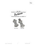
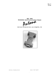
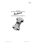
ANC-1008 IBM Pc/XT/AT Compatible Discrete Relay Card
1.0 Overview
♦
♦
♦
♦
♦
♦
♦
♦
Discrete relays with "C" type configuration
Programmable directly in BASIC
Relays handle 115 VAC at 1 Amp.
LED display of card and relay status
User selectable I/O address
Read-back of relay output condition
System reset opens all relays
User snubber capacitor locations for all contacts
Providing 8 - "C" type discrete relay contacts for general purpose application the
ANC-1008 occupies a short card slot in the IBM Pc, /XT, /AT or IBM System/2-30
computer. Each relay provides a normally open and normally closed output ("C" type
configuration). The card occupies a short card slot in the Pc and signal output is obtained
by way of a DB-25 "D" shell type connector. Upon system power-up or system reset, all of
the relays are initialized in a "off" condition. The user may then set the desired relay
configuration and enable the relay drivers. A 9-LED display array, viewable under the rear
mounted DB-25 connector, shows card reset and relay status. The ANC-1008 uses a
single user selectable I/O address for its operation and the output relay configuration may
be read back into the Pc. The user may add capacitors across each of the normally open
and normally closed contacts to attenuate noise when switching DC voltages.
Programming can be performed directly in BASIC or by ASSEMBLY LANGUAGE.
The appendix included provides sample driver software which designers may use as a
basis for developing their own device drivers.
1.1 Card Initialization
Upon power-up, all relays are initialized off. The user may of course, use the
normally closed contact on any of the discrete relays so that at power-up a circuit is closed
rather than open. Upon system power-up the card's relay latch register should be loaded
with the desired relay configuration, and then a 'dummy' read operation is performed to
enable the relay drivers. A sample initialization program is included as Appendix A of this
manual.
The general procedure for initialization of the card is as follows:
1. Setting the initial condition of the relays on the card.
2.Enable the relay card for operation by doing a "read" of the relay status
port (same address as relay control port).
3 Transfer control to start execution of user stored BASIC (or ASSEMBLY
LANGUAGE program).
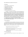
1.3.1 I/O Port Addressing
The following table details the address and function performed for I/O port
operation.
1
Card
bit weight
Port 9 8 7 6 5 4 3 2 1 0
Hex Value
as Shipped
XX XXXX XXXX
XX XXXX XXXX
310H
310H
Comment
8-bit relay control port
8-bit relay status port
Note that the "X"s are user selected bits set on the 10-bit switch on the ANC-1008 card.
The user has the ability to set the card to any single I/O address.
The output/input bits are directed to the 25-pin "D" shell connector located at the
right side of the ANC-1008 card. See the hardware connector section or schematic for
pinouts.
RELAY DATA PORT
Bit Wt.
0
1
2
3
4
5
6
7
Function
"1" = turn relay D0 on, "0" = turn relay off
"1" = turn relay D1 on, "0" = turn relay off
"1" = turn relay D2 on, "0" = turn relay off
"1" = turn relay D3 on, "0" = turn relay off
"1" = turn relay D4 on, "0" = turn relay off
"1" = turn relay D5 on, "0" = turn relay off
"1" = turn relay D6 on, "0" = turn relay off
"1" = turn relay D7 on, "0" = turn relay off
The user should note that the "sense" of the bit is "TRUE" in that writing a "1" turns
on a relay. Operating the card in BASIC consists of the following command:
OUT RELAY,(Variable)
Where "RELAY" is the data port address, and "variable" is the byte of data desired to
output to the relay card.
SOME EXAMPLES:
OUT &H310,&H80
;TURN ON D7 RELAY, ALL OTHERS OFF
OUT &H310,&H81
;TURN ON D7 AND D0 RELAY
OUT&H310,(INP(&H310)+&H04)
;READ CURRENT STATE,
;COMBINE IN RELAY D2
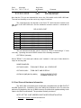
2.0 Card General Hardware Information
The ANC-1008 is electrically and mechanically compatible with the IBM Pc/XT/AT
and IBM System/2-30. Installation of the card within the mainframe of the Pc should be
performed as detailed by the any of IBM's Inventory Checklist which explains adding circuit
cards to the IBM Pc motherboard. The procedure basically consists of:
NOTE: SET THE 10-BIT ADDRESS SWITCH BEFORE INSTALLATION.
1. Remove the power cord from the base unit
2
2. Remove the screws on the back of the unit, and pull the unit cover
forward.
3. Remove the metal plate at any unused card slot location, you will need
the #6-32 screw.
4. Install the ANC-1008 Card (set card address before insertion).Refasten
#6-32 removed from step 3.
5. Replace cover, screws and power cord last. Connect the mating male
DB-25 cable connector to ANC-1008 at rear of unit.
NOTE: For System/2-30 User's, follow the procedure that IBM details within the
PS/2-30 User's Manual.
2.1 Card Hardware Options
The following sections detail the use and changes of the strap options on the circuit
card. Note that the following instructions apply to all products manufactured by ANTONA
CORP.
To properly identify the pin locations, the card should be placed component side-up with
the card's gold connector pointed towards you. The "common connection" designates
where one end of the jumper should always be connected to the desired card action or
operation. Some jumpers merely enable functions (like interrupt vector), while others allow
selection of hardware modes of operation. Some of the strap options require a circuit
trace on the solder side of the card between pads to be cut with an X-Acto Knife or Dremel
Tool.
3
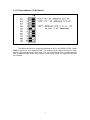
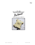
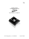
2.1.1.0 Card Address - 10-Bit Switch
Figure 2.1
The switch can be set to occupy any address on the Pc from 000H to 3F8H. When
shipped, the card is set to address 310H. This means that the relay control port is 310H,
and the relay read-back port is also 310H. The user must take care not to assign the relay
card an address which would conflict with the other option cards and system functions of
the computer.
4
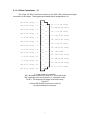
2.1.1.4 Cable Connections - J1
The 25-pin I/O DB 25 connector located on the ANC-1008 provides input/output
connection for all 8 relays. The diagram below details the pin assignments of J1:
NC of D4 relay - 1
NO of D0 relay - 2
NC of D0 relay - 3
NO of D1 relay - 4
C of D1 relay - 5
NC of D2 relay - 6
NO of D3 relay - 7
C of D3 relay - 8
NC of D5 relay - 9
C of D5 relay -10
C of D6 relay -11
NO of D7 relay -12
NC of D7 relay -13
|
|
|
|
|
|
|
|
|
|
|
|
|
|
|
|
|
|
|
|
|
|
|
|
|
o
o
o
o
o
o
o
o
o
o
o
o
o
o
o
o
o
o
o
o
o
o
o
o
14 - C of D4 relay
|
|
|
|
|
|
|
|
|
|
|
|
|
|
|
|
|
|
|
|
|
15 - NO of D4 relay
16 - C of D0 relay
17 - NC of D1 relay
18 - NO of D2 relay
19 - C of D2 relay
20 - NC of D3 relay
21 - not used
22 - NO of D5 relay
23 - NO of D6 relay
24 - NC of D6 relay
25 - C of D7 relay
o
C = relay Common connection
NC = Normally Closed circuit (relay off, C connected to NC)
NO = Normally Open circuit (relay on, C connected to NO)
D0-D7 = The respective bit weight to control the relay
Figure 2.2
J1 25-pin DB 25 cable connector for relay I/O
as viewed looking into connector
5
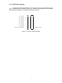
2.1.1.5 LED Status Display
programmer with a visual display of the relay status and relay enable state (green
LED). An illuminated LED indicates a relay "on" condition, and the green LED on indicates
that the relays are enabled. The display definition is as follows:
D7 RELAY
D6 RELAY
D5 RELAY
D4 RELAY
D3 RELAY
D2 RELAY
D1 RELAY
D0 RELAY
RELAYS ENABLED
8
7
6
5
4
3
2
1
O
O
O
O
O
O
O
O
*
(GREEN LED)
Figure 2.3 - Relay / Card Status LEDs
6
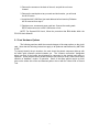
3.0 Software Operation
The ANC-1008 may be controlled under BASIC or Assembly Language (or ANY
language which can control discrete Pc Input / Output addresses). The most common use
is probably with BASIC, but in applications where speed of operation is critical Assembly
Language may be the only choice. Note that a user may write driver software that is
"CALLed" from BASIC.
Driver software may be divided into 2 basic tasks, initialization and writing to the
card. Initialization should be performed as soon after power up as possible. The designer
should consider this factor if the ANC-1008 is intended for control application where drive
signals could be applied with the card uninitialized. A common practice is to have one
output bit assigned as a low enabled "system enable". In this way only after the card has
been initialized and the enable bit set, will the control signals to the peripheral device under
control be honored. In all cases the designer is responsible for handling powerfail or other
computer problems. Once the relay card is initialized, the user need only format the 8-bit
data to output and write it to the data port for operation. This process may sound
complicated, but really is not. Examine the sample BASIC driver in Appendix A to get a
better feel for the whole operation.
7
Appendix A - Sample Card Program
The following listing provides a sample software driver for card initialization, and
writing - it is a sample only and is not supported in any way by the Antona Corporation. It is
supplied only as a basis for the purchaser of the ANC-1008 to get an idea of the
capabilities and features of the card.
10 REM
20 REM ANC-1008 SAMPLE TEST DRIVER
30 REM
40 REM CARD SET TO ADDR 310H
50 REM
60 A=&H310
70 REM
80 REM SET PORT UP FOR OUTPUT
90 REM
100 OUT A,&H0
110 Z=INP(A)
120 REM
130 REM ON/OFF BIT ON PORT
140 REM
150 OUT A,0
160 PRINT: PRINT
170 PRINT "RELAY PORT"
180 IF (INP(A)) THEN SOUND 100,10
190 PRINT HEX$(INP(A))
200 INPUT "
RELAYS OFF (00) - PRESS ENTER",A$
210 OUT A,255
220 IF (255-INP(A)) THEN SOUND 100,10
230 PRINT HEX$(INP(A))
240 INPUT "
LAMPS ON (FF) - PRESS ENTER",A$
250 REM
260 REM OUTPUT ALL POSSIBLE BINARY PATTERNS TO THE PORT
270 REM
280 PRINT "BINARY COUNT TO TOGGLE ALL RELAYS - PRESS ENTER"
290 FOR X=0 TO 255
300 OUT A,X
310 IF (X-INP(A)) THEN SOUND 500,1:PRINT HEX$(X),HEX$(INP(A))
320 A$=INKEY$
330 IF LEN(A$)=1 THEN GOTO 410
340 NEXT X
350 REM
360 SOUND 2000,1:PRINT "PASS ";
370 GOTO 290
380 REM
390 REM TOGGLE BITS ON/OFF LIKE RING
400 REM
410 PRINT:PRINT "WALKING 0'S TEST IN RING - PRESS ANY KEY FOR NEXT"
420 V=&HFE:Y=1
430 FOR X=0 TO 7
440 OUT A,V: OUT B,V: OUT C,V
450 Y=Y*2: V=&HFF-Y
460 A$=INKEY$
470 IF LEN(A$)=1 THEN GOTO 550
480 FOR Z=1 TO 100
490 NEXT Z
8
500 NEXT X
510 FOR Z=1 TO 50
520 NEXT Z
530 GOTO 420
540 REM
550 PRINT "WALKING 1'S TEST IN RING - PRESS ANY KEY TO REPEAT"
560 V=1:Y=1
570 FOR X=0 TO 7
580 OUT A,V: OUT B,V: OUT C,V
590 Y=Y*2: V=Y
600 A$=INKEY$
610 IF LEN(A$)=1 THEN GOTO 150
620 FOR Z=1 TO 100
630 NEXT Z
640 NEXT X
650 FOR Z=1 TO 50
660 NEXT Z
670 GOTO 560
9
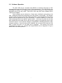
Appendix B High Voltage Shield
HIGH-VOLTAGE SHIELD FOR ANC-1008 DISCRETE RELAY CARD
The ANC-1008 is now shipped with an optional high-voltage shield for use, if
appropriate, with the 8-channel relay card. As the user may be switching high-voltage (and
hopefully low current) loads with the ANC-1008, installation of the shield adds another level
of protection to the card. For user's who are only switching 5v to 24v through the relay
card, the shield is probably not necessary. Mounting of the shield is accomplished by the
following procedure:
1. If connected, disconnect the user supplied DB-25 from the ANC-1008 card.
2. Press the nylon 4-40 screws through the component side of the circuit board at the 4
silk-screened circled hole sites (screws have a tight fit).
3. Next on the solder side of the card, place the 4 nylon spacers onto each screw.
4. Remove the protective sticky paper on both sides of the clear plastic shield and then
place it onto the 4 protruding 4-40 screw shafts on the solder side of card. It will only fit on
one-way due to the offset screw placed near the board-mounted DB-25 (J1).
5. Lastly, use the nylon 4-40 nuts to secure the shield to the relay card. The protruding
nylon screw shafts can be cut off with a pair of diagonals or wire cutters.
10
Appendix C Circuit Card Schematic
The following pages contain the electronic schematics for the ANC-1008 to be used
help in understanding the operation of the relay card.
11