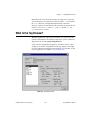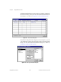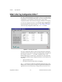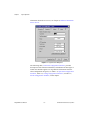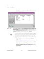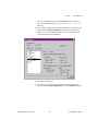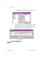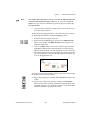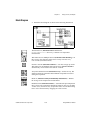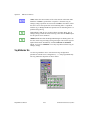
1
BridgeVIEW™
User Manual
BridgeVIEW User Manual
October 1996 Edition
Part Number 321294A-01
© Copyright 1996 National Instruments Corporation. All rights reserved.
Internet Support
BridgeVIEW: [email protected]
E-mail: [email protected]
FTP Site: ftp.natinst.com
Web Address: http://www.natinst.com
Bulletin Board Support
BBS United States: (512) 794-5422 or (800) 327-3077
BBS United Kingdom: 01635 551422
BBS France: 01 48 65 15 59
FaxBack Support
(512) 418-1111
Telephone Support (U.S.)
Tel: (512) 795-8248
Fax: (512) 794-5678
International Offices
Australia 03 9879 5166, Austria 0662 45 79 90 0, Belgium 02 757 00 20,
Canada (Ontario) 905 785 0085, Canada (Québec) 514 694 8521, Denmark 45 76 26 00,
Finland 90 527 2321, France 01 48 14 24 24, Germany 089 741 31 30, Hong Kong 2645 3186,
Israel 03 5734815, Italy 02 413091, Japan 03 5472 2970, Korea 02 596 7456,
Mexico 95 800 010 0793, Netherlands 0348 433466, Norway 32 84 84 00, Singapore 2265886,
Spain 91 640 0085, Sweden 08 730 49 70, Switzerland 056 200 51 51, Taiwan 02 377 1200,
U.K. 01635 523545
National Instruments Corporate Headquarters
6504 Bridge Point Parkway
Austin, TX 78730-5039
Tel: (512) 794-0100
Important Information
Warranty
The media on which you receive National Instruments software are warranted not to fail to execute programming
instructions, due to defects in materials and workmanship, for a period of 90 days from date of shipment, as evidenced
by receipts or other documentation. National Instruments will, at its option, repair or replace software media that do
not execute programming instructions if National Instruments receives notice of such defects during the warranty
period. National Instruments does not warrant that the operation of the software shall be uninterrupted or error free.
A Return Material Authorization (RMA) number must be obtained from the factory and clearly marked on the outside
of the package before any equipment will be accepted for warranty work. National Instruments will pay the shipping
costs of returning to the owner parts which are covered by warranty.
National Instruments believes that the information in this manual is accurate. The document has been carefully
reviewed for technical accuracy. In the event that technical or typographical errors exist, National Instruments reserves
the right to make changes to subsequent editions of this document without prior notice to holders of this edition. The
reader should consult National Instruments if errors are suspected. In no event shall National Instruments be liable for
any damages arising out of or related to this document or the information contained in it.
EXCEPT AS SPECIFIED HEREIN , NATIONAL INSTRUMENTS MAKES NO WARRANTIES, EXPRESS OR IMPLIED, AND
SPECIFICALLY DISCLAIMS ANY WARRANTY OF MERCHANTABILITY OR FITNESS FOR A PARTICULAR PURPOSE .
CUSTOMER’S RIGHT TO RECOVER DAMAGES CAUSED BY FAULT OR NEGLIGENCE ON THE PART OF N ATIONAL
INSTRUMENTS SHALL BE LIMITED TO THE AMOUNT THERETOFORE PAID BY THE CUSTOMER . NATIONAL INSTRUMENTS
WILL NOT BE LIABLE FOR DAMAGES RESULTING FROM LOSS OF DATA , PROFITS , USE OF PRODUCTS, OR INCIDENTAL OR
CONSEQUENTIAL DAMAGES , EVEN IF ADVISED OF THE POSSIBILITY THEREOF. This limitation of the liability of National
Instruments will apply regardless of the form of action, whether in contract or tort, including negligence. Any action
against National Instruments must be brought within one year after the cause of action accrues. National Instruments
shall not be liable for any delay in performance due to causes beyond its reasonable control. The warranty provided
herein does not cover damages, defects, malfunctions, or service failures caused by owner’s failure to follow the
National Instruments installation, operation, or maintenance instructions; owner’s modification of the product;
owner’s abuse, misuse, or negligent acts; and power failure or surges, fire, flood, accident, actions of third parties, or
other events outside reasonable control.
Copyright
Under the copyright laws, this publication may not be reproduced or transmitted in any form, electronic or mechanical,
including photocopying, recording, storing in an information retrieval system, or translating, in whole or in part,
without the prior written consent of National Instruments Corporation.
Trademarks
BridgeVIEW™, LabVIEW® , National Instruments™, natinst.com™, and NI-DAQ® are trademarks of National
Instruments Corporation.
Product and company names listed are trademarks or trade names of their respective companies.
WARNING REGARDING MEDICAL AND CLINICAL USE OF NATIONAL INSTRUMENTS PRODUCTS
National Instruments products are not designed with components and testing intended to ensure a level of reliability
suitable for use in treatment and diagnosis of humans. Applications of National Instruments products involving
medical or clinical treatment can create a potential for accidental injury caused by product failure, or by errors on the
part of the user or application designer. Any use or application of National Instruments products for or involving
medical or clinical treatment must be performed by properly trained and qualified medical personnel, and all traditional
medical safeguards, equipment, and procedures that are appropriate in the particular situation to prevent serious injury
or death should always continue to be used when National Instruments products are being used. National Instruments
products are NOT intended to be a substitute for any form of established process, procedure, or equipment used to
monitor or safeguard human health and safety in medical or clinical treatment.
Table
of
Contents
About This Manual
Organization of This Manual ...........................................................................................xix
BridgeVIEW Concepts......................................................................................xx
G Tutorial ..........................................................................................................xxi
Appendices, Glossary, and Index ......................................................................xxii
Conventions Used in This Manual...................................................................................xxii
Related Documentation....................................................................................................xxiii
Customer Communication ...............................................................................................xxiv
BridgeVIEW Concepts—Chapter 1 through Chapter 8
Chapter 1
Introduction
Welcome To BridgeVIEW! .............................................................................................1-1
Required System Configuration ........................................................................1-2
Installing BridgeVIEW......................................................................................1-2
What Is BridgeVIEW?.....................................................................................................1-3
How Does BridgeVIEW Work? ......................................................................................1-3
G Programming .................................................................................................1-4
Tag Configuration .............................................................................................1-5
Data Type............................................................................................1-5
Connection ..........................................................................................1-6
Scaling.................................................................................................1-6
Operations ...........................................................................................1-6
Alarms ...............................................................................................................1-6
Events ................................................................................................................1-7
Historical Data Logging and Extraction............................................................1-7
Security..............................................................................................................1-7
What Is the BridgeVIEW System Architecture? .............................................................1-8
User MMI Application ......................................................................................1-9
BridgeVIEW Engine .........................................................................................1-9
Industrial Automation Device Servers ..............................................................1-9
Where Should I Start?......................................................................................................1-10
© National Instruments Corporation
v
BridgeVIEW User Manual
Table of Contents
Chapter 2
BridgeVIEW Environment
What Is G?....................................................................................................................... 2-1
How Does G Work? ........................................................................................................ 2-2
Virtual Instruments ........................................................................................... 2-2
Front Panel.......................................................................................... 2-2
Block Diagram.................................................................................... 2-3
Icon/Connector ................................................................................... 2-4
Tools Palette...................................................................................................... 2-4
Controls Palette ................................................................................................. 2-5
Functions Palette ............................................................................................... 2-6
Controls and Indicators ..................................................................................... 2-6
Numeric .............................................................................................. 2-7
Boolean ............................................................................................... 2-7
String .................................................................................................. 2-7
Tag ...................................................................................................... 2-8
BridgeVIEW Environment Project Menu ....................................................................... 2-11
What Is the BridgeVIEW Engine Manager? ................................................................... 2-13
What Are System Errors and Events? ............................................................................. 2-16
What Is the Tag Browser? ............................................................................................... 2-17
What Is the Tag Monitor?................................................................................................ 2-20
How Do You Access Online Help?................................................................................. 2-23
Simple/Complex Help View ............................................................................. 2-23
Links to Online Help Files ................................................................................ 2-24
Chapter 3
Tag Configuration
What Is a Tag?................................................................................................................. 3-1
What Is the Tag Configuration Editor? ........................................................................... 3-2
How Do You Create, Edit, or Delete a Tag? .................................................... 3-3
How Do You Edit Multiple Tags Simultaneously? .......................................... 3-3
How Do You Set Default Values for Tag Configuration Fields? ..................... 3-4
How Do You Use Spreadsheet Files for Tag Configuration?........................... 3-4
How Do You Configure Tags?........................................................................................ 3-6
Data Type.......................................................................................................... 3-6
Analog Tags........................................................................................ 3-7
Discrete Tags ...................................................................................... 3-7
Bit Array Tags .................................................................................... 3-7
String Tags.......................................................................................... 3-7
BridgeVIEW User Manual
vi
© National Instruments Corporation
Table of Contents
Connection.........................................................................................................3-7
What is a Memory Tag?......................................................................3-10
When Should You Use a Memory Tag?...............................3-10
Example 1—When Not to Use a Memory Tag ......3-10
Example 2—When to Use a Memory Tag .............3-11
How Do You Import Items from the Server Registry?.......................3-11
How Do You Connect a Tag to a DDE Server? .................................3-12
How Do You Define a Group of Tags for Alarming? ........................3-12
Operations..........................................................................................................3-12
What Is Deadband? .............................................................................3-15
How Do You Use Deadband to Increase Engine Throughput? ..........3-15
How Do You Configure a Tag to Log Its Data or Events?.................3-16
How Do You Set Initial Tag Value at Startup? ..................................3-16
Scaling ...............................................................................................................3-16
Analog Tags ........................................................................................3-18
Example—Linear Scaling.....................................................3-19
Example—Square Root Scaling ...........................................3-19
How Do You Assign Units to an Analog Tag?...................................3-19
Discrete Tags.......................................................................................3-19
Bit Array Tags.....................................................................................3-20
Alarms ...............................................................................................................3-21
How Do You Configure Alarms for a Tag?........................................3-24
Analog Tags..........................................................................3-25
Discrete Tags ........................................................................3-25
Bit Array Tags ......................................................................3-26
String Tags............................................................................3-27
What Is Alarm Deadband on Analog Tags? .......................................3-27
How Do You Keep an Alarm Unacknowledged after the Alarm
Returns to Normal? ..........................................................................3-28
Auto Ack on Normal ............................................................3-29
User Must Ack......................................................................3-29
How Do You Configure Other Engine Parameters?........................................................3-35
How Do You Turn on Historical and Event Logging at Startup? .....................3-35
How Do You Set the File Paths for Historical and Events Files? .....................3-35
How Do You Configure Shifts? ........................................................................3-35
How Do You Configure Engine Parameters? ...................................................3-35
How Do You Launch Server Configuration Utilities from the Tag
Configuration Editor? .....................................................................................3-36
How Do You Access or Change Tag Configuration Information
in Your Application?.....................................................................................................3-37
© National Instruments Corporation
vii
BridgeVIEW User Manual
Table of Contents
Chapter 4
Man Machine Interface
What Is an MMI?............................................................................................................. 4-1
How Do You Build an MMI?.......................................................................................... 4-2
Front Panel Objects ........................................................................................... 4-3
MMI G Wizard.................................................................................................. 4-3
Generate the Block Diagram .............................................................. 4-7
Front Panel Object and Wizard Subdiagram Association .................. 4-7
How Do You Customize Front Panel Objects? ................................................ 4-11
Control Editor ..................................................................................... 4-11
Importing Graphics............................................................................. 4-12
How Do You Configure Front Panel Objects Programmatically? ..... 4-15
How Do You Monitor and Control Tags?....................................................................... 4-15
Tag Data Type................................................................................................... 4-16
Tags VIs and Alarms and Events VIs ............................................................... 4-18
Front Panel ........................................................................................................ 4-20
Block Diagram .................................................................................................. 4-20
How Do the Tags, and Alarms and Events VIs Affect
Startup/Shutdown?........................................................................... 4-23
General Principles of G MMI Programming................................................................... 4-23
How Do You Implement Event-Driven Programming in G? ........................... 4-24
How Do You Implement Polled Programming in G?....................................... 4-26
How Do You Initialize and Shut Down Multiple-Loop Applications? ............ 4-27
How Do You Display Real-Time Trends?........................................................ 4-28
How Can You Use Tag Attributes to Configure MMI Indicators
Programmatically? ......................................................................................... 4-30
Chapter 5
Alarms and Events
What are Alarms and Events? ......................................................................................... 5-1
Alarm States ...................................................................................................... 5-1
Alarm Limit....................................................................................................... 5-1
Alarm Priority ................................................................................................... 5-2
Alarm Summary ................................................................................................ 5-2
Event History .................................................................................................... 5-2
How Do You Display Alarm Summary Information? .................................................... 5-2
How Do You Display Event History Information?......................................................... 5-6
How Do You Acknowledge Alarms?.............................................................................. 5-7
How Do You Configure Logging and Printing of Alarms and Events?.......................... 5-10
How Do You Log Alarms and Events? ............................................................ 5-13
How Do You Print Alarms and Events? ........................................................... 5-14
How Do You View Alarms and Events? .......................................................... 5-14
BridgeVIEW User Manual
viii
© National Instruments Corporation
Table of Contents
Chapter 6
Historical Data Logging and Extraction
What Is a Trend?..............................................................................................................6-1
Real-Time Trend ...............................................................................................6-1
Historical Trend.................................................................................................6-1
What is Citadel?...............................................................................................................6-2
How Do You Log Historical Data? .................................................................................6-2
How Do You Configure Historical Logging? ...................................................6-3
How Do You Extract and View Data from Historical Log Files?...................................6-4
Historical Data VIs ............................................................................................6-4
Historical Trend Viewer (HTV) ........................................................................6-9
How Do You Select the Tags To Display? .........................................6-10
How Do You Change the Time Axis? ................................................6-11
Panning Buttons....................................................................6-11
Manual Changes ...................................................................6-11
How Do You Change the Timespan of Data Displayed? ...................6-12
How Do You View the Value of a Tag at a Specific Point
in Time? ...........................................................................................6-12
How Do You Change the Y Axis?......................................................6-12
How Do You Change the Plot Colors and Style in the Trend?...........6-13
How Do You Zoom In on the Trend? .................................................6-13
How Do You Export Data to a Spreadsheet?......................................6-13
How Do You Get Online Help for the HTV?....................................................6-13
How Do You Set Tag, Time, and Color Preferences? ........................6-14
How Do You Incorporate the HTV into Your MMI Application? .....6-14
Chapter 7
Advanced Application Topics
BridgeVIEW System Control ..........................................................................................7-1
System VIs.........................................................................................................7-1
How Do You Start or Stop the BridgeVIEW Engine from Your
Application? .....................................................................................7-2
How Do You Start or Stop Historical Logging from Your
Application? .....................................................................................7-2
How Do You Start or Stop Event Logging from Your
Application? .....................................................................................7-2
How Do You Start or Stop Event Printing from Your
Application? .....................................................................................7-2
VI Control VIs...................................................................................................7-2
How Do You Control Panel Size? ......................................................7-3
How Do You Control Panel Visibility? ..............................................7-3
Tag Attributes VIs ...........................................................................................................7-4
© National Instruments Corporation
ix
BridgeVIEW User Manual
Table of Contents
BridgeVIEW Security ..................................................................................................... 7-8
Environment Security ....................................................................................... 7-8
How Do You Log In and Out? ........................................................... 7-9
How Do You Find Your Access Level? ............................................. 7-9
How Do You Find Your Environment Access Privileges? ................ 7-10
How Do You Change Your Password? .............................................. 7-10
How Do You Prompt the Operator to Log In to Your
Application?..................................................................................... 7-11
How Do You Identify the Current Operator? ..................................... 7-11
How Do You Restrict Access to the BridgeVIEW Environment? ..... 7-11
How Do You Create and Modify User Accounts? ............................. 7-11
How Do You Modify the List of Available User Access Levels? ..... 7-12
How Do You Modify Access Privileges in the BridgeVIEW
Environment?................................................................................... 7-13
Operator Interface Security ............................................................................... 7-14
How Do You Limit User Access to MMI Objects? ........................... 7-14
Chapter 8
Industrial Automation Device Servers
What Are Industrial Automation (IA) Device Servers? .................................................. 8-1
How Do You Install and Configure a Device Server? .................................................... 8-2
Installing and Configuring the NI-DAQ Server................................................ 8-3
Installing and Configuring Device Servers from the BridgeVIEW Device
Servers CD ..................................................................................................... 8-4
Registering Simulation Servers......................................................................... 8-4
How Do You View BridgeVIEW Server Configuration?............................................... 8-5
Registered Server Device and Item Parameters ................................................ 8-7
How Do You Use DDE Servers with BridgeVIEW?...................................................... 8-8
How Do You Develop an IA Device Server? ................................................................. 8-9
G Tutorial—Chapter 9 through Chapter 15
Chapter 9
Creating and Customizing VIs
What is a Virtual Instrument?.......................................................................................... 9-1
How Do You Build a VI?................................................................................................ 9-1
VI Hierarchy ..................................................................................................... 9-1
Controls, Constants, and Indicators .................................................................. 9-2
Terminals .......................................................................................................... 9-4
BridgeVIEW User Manual
x
© National Instruments Corporation
Table of Contents
Wires..................................................................................................................9-4
Tip Strips.............................................................................................9-5
Wire Stretching ...................................................................................9-6
Selecting and Deleting Wires..............................................................9-6
Bad Wires............................................................................................9-7
VI Documentation .............................................................................................9-11
What is a SubVI? .............................................................................................................9-13
Hierarchy Window ............................................................................................9-14
Search Hierarchy.................................................................................9-15
Icon and Connector............................................................................................9-15
Opening, Operating, and Changing SubVIs ......................................................9-20
Front Panel.........................................................................................................9-20
Block Diagram...................................................................................................9-21
How Do You Debug a VI? ..............................................................................................9-23
How Do You Customize a VI? ........................................................................................9-26
Set Window Options..........................................................................................9-26
SubVI Node Setup.............................................................................................9-26
Front Panel ..........................................................................................9-28
Block Diagram ....................................................................................9-28
Front Panel............................................................................9-31
Block Diagram......................................................................9-32
Chapter 10
Loops and Charts
What is a Structure? .........................................................................................................10-1
Charts ...............................................................................................................................10-2
Chart Modes ......................................................................................................10-2
Faster Chart Updates .........................................................................................10-3
Stacked Versus Overlaid Plots ..........................................................................10-3
While Loops.....................................................................................................................10-4
Front Panel.........................................................................................................10-5
Block Diagram...................................................................................................10-6
Mechanical Action of Boolean Switches ..........................................................10-7
Timing ...............................................................................................................10-9
Preventing Code Execution in the First Iteration ..............................................10-11
Shift Registers..................................................................................................................10-12
Front Panel.........................................................................................................10-14
Block Diagram...................................................................................................10-14
Using Uninitialized Shift Registers ...................................................................10-16
Front Panel.........................................................................................................10-18
Block Diagram...................................................................................................10-19
© National Instruments Corporation
xi
BridgeVIEW User Manual
Table of Contents
For Loops......................................................................................................................... 10-21
Numeric Conversion ......................................................................................... 10-23
Front Panel ........................................................................................................ 10-24
Block Diagram .................................................................................................. 10-24
Chapter 11
Case and Sequence Structures
Case Structure.................................................................................................................. 11-1
Front Panel ........................................................................................................ 11-2
Block Diagram .................................................................................................. 11-3
VI Logic ............................................................................................................ 11-4
Sequence Structures......................................................................................................... 11-5
Front Panel ........................................................................................................ 11-5
Block Diagram .................................................................................................. 11-6
Chapter 12
Attribute Nodes
Front Panel ........................................................................................................ 12-3
Block Diagram .................................................................................................. 12-4
Chapter 13
Arrays, Clusters, and Graphs
What is Polymorphism? .................................................................................................. 13-1
Arrays .............................................................................................................................. 13-2
How Do You Create and Initialize Arrays? ...................................................... 13-2
Array Controls, Constants, and Indicators.......................................... 13-3
Auto-Indexing ................................................................................................... 13-3
Front Panel ........................................................................................................ 13-4
Block Diagram .................................................................................................. 13-5
Multiplot Graphs ............................................................................................... 13-8
Using Auto-Indexing to Set the For Loop Count.............................................. 13-10
Using Array Functions ...................................................................................... 13-11
Build Array ......................................................................................... 13-11
Initialize Array.................................................................................... 13-12
Array Size ........................................................................................... 13-13
Array Subset ....................................................................................... 13-14
Index Array......................................................................................... 13-14
Front Panel ........................................................................................................ 13-17
Block Diagram .................................................................................................. 13-18
Efficient Memory Usage: Minimizing Data Copies ......................................... 13-18
Clusters ............................................................................................................................ 13-19
BridgeVIEW User Manual
xii
© National Instruments Corporation
Table of Contents
Graphs ..............................................................................................................................13-19
Customizing Graphs ..........................................................................................13-19
Graph Cursors .....................................................................................13-20
Graph Axes .........................................................................................13-21
Data Acquisition Arrays ....................................................................................13-21
Front Panel.........................................................................................................13-22
Block Diagram...................................................................................................13-23
Chapter 14
VI Control VIs
What Are VI Control VIs? ................................................................................14-2
Front Panel.........................................................................................................14-4
Block Diagram...................................................................................................14-5
Chapter 15
Program Design
Use Top-Down Design ....................................................................................................15-1
Make a List of User Requirements....................................................................15-1
Design the VI Hierarchy....................................................................................15-1
Write the Program .............................................................................................15-3
Plan Ahead with Connector Panes...................................................................................15-3
SubVIs with Required Inputs ............................................................................15-4
Good Diagram Style ........................................................................................................15-5
Watch for Common Operations.........................................................................15-5
Use Left-to-Right Layouts.................................................................................15-6
Check for Errors ................................................................................................15-6
Avoid Overuse of Sequence Structures.............................................................15-8
Study the Examples ...........................................................................................15-8
Appendix A
MMI Function Reference
Error Handling in the BridgeVIEW VI Library...............................................................A-1
Errors Reported by the BridgeVIEW Engine....................................................A-1
Errors Not Reported by the BridgeVIEW Engine.............................................A-1
BridgeVIEW VI Library ..................................................................................................A-3
Alarms and Events VIs......................................................................................A-4
Acknowledge Alarm ..........................................................................A-4
Get Alarm Summary Status ...............................................................A-5
Read Alarm Summary ........................................................................A-6
Read Event History ............................................................................A-9
Read Tag Alarm .................................................................................A-13
© National Instruments Corporation
xiii
BridgeVIEW User Manual
Table of Contents
Historical Data VIs............................................................................................ A-15
Call HTV ........................................................................................... A-15
Decimate Historical Trend ................................................................. A-17
Decimate Historical Trends ............................................................... A-18
Get Historical Tag List ...................................................................... A-19
Get Historical Trend Info .................................................................. A-20
Historical Trend Statistics ................................................................. A-21
Historical Trends to Spreadsheet ....................................................... A-22
Read Historical Trend ........................................................................ A-24
Read Historical Trends ...................................................................... A-25
System VIs ........................................................................................................ A-27
Enable Event Logging ....................................................................... A-27
Enable Historical Data Logging ........................................................ A-28
Enable Printing .................................................................................. A-28
Engine Launch ................................................................................... A-29
Engine Shutdown ............................................................................... A-30
Get Operator Name ............................................................................ A-30
Get Tag Status Info ............................................................................ A-30
Invoke Login Dialog .......................................................................... A-31
Post System Error or Event ............................................................... A-32
Security Monitor ................................................................................ A-32
Tag Status Handler ............................................................................ A-33
Tags VIs ............................................................................................................ A-35
Read Tag ............................................................................................ A-35
Read Tag (bit array) ........................................................................... A-37
Read Tag (discrete) ............................................................................ A-38
Read Tag (string) ............................................................................... A-40
Trend Tags ......................................................................................... A-41
Write Tag ........................................................................................... A-42
Write Tag (bit array) .......................................................................... A-43
Write Tag (discrete) ........................................................................... A-44
Write Tag (string) .............................................................................. A-45
Write Tag on Change ......................................................................... A-46
Write Tag on Change (bit array) ........................................................ A-47
Write Tag on Change (discrete) ......................................................... A-48
Write Tag on Change (string) ............................................................ A-49
Tag Attributes VIs............................................................................................. A-50
Get Analog Tag Alarm Limit ............................................................ A-51
Get Bit Array Tag Alarm Setting ...................................................... A-52
Get Discrete Tag Alarm Setting ........................................................ A-53
Get Group List ................................................................................... A-54
Get Tag Alarm Enabled ..................................................................... A-54
Get Tag Attribute ............................................................................... A-55
BridgeVIEW User Manual
xiv
© National Instruments Corporation
Table of Contents
Get Tag Bad Status Alarm Info ..........................................................A-56
Get Tag Description Group ................................................................A-57
Get Tag IO Connection Info ..............................................................A-57
Get Tag List .......................................................................................A-58
Get Tag Logging Info ........................................................................A-59
Get Tag Range and Units ...................................................................A-60
Set Multiple Tag Attributes ................................................................A-61
Set Tag Attribute ................................................................................A-62
Appendix B
Citadel and Open Database Connectivity
Appendix C
Customer Communication
Glossary
Index
Figures
Figure 1-1.
BridgeVIEW Architecture ......................................................................1-8
Figure 2-1.
Figure 2-2.
Figure 2-3.
Figure 2-4.
Figure 2-5.
Figure 2-6.
Engine Manager Display ........................................................................2-13
Engine Manager with System Events Displayed ...................................2-15
Tag Browser Utility ................................................................................2-17
Tag Monitor Utility ................................................................................2-20
Status Details Dialog Box ......................................................................2-22
Select Tags to Monitor Dialog Box ........................................................2-22
Figure 3-1.
Figure 3-2.
Figure 3-3.
Figure 3-4.
Figure 3-5.
Figure 3-6.
Figure 3-7.
Figure 3-8.
Figure 3-9.
Tag Configuration Editor .......................................................................3-2
Tag Connection Dialog Box ...................................................................3-8
Tag Operations Dialog Box ....................................................................3-13
Analog Tag Scaling Dialog Box ............................................................3-18
Scaling for Discrete Tag Configuration .................................................3-20
Scaling for Bit Array Tag Configuration ...............................................3-21
Alarms for Analog Tag Configuration ...................................................3-25
Alarms for Discrete Tag Configuration ..................................................3-26
Alarms for Bit Array Tag Configuration ................................................3-27
© National Instruments Corporation
xv
BridgeVIEW User Manual
Table of Contents
Figure 4-1.
Figure 4-2.
Figure 4-3.
Figure 4-4.
Figure 4-5.
Figure 4-6.
Figure 4-7.
Figure 4-8.
MMI G Wizard Dialog Box ................................................................... 4-6
Control Dialog Box ................................................................................ 4-11
Monitor Tag Value and Alarm VI ......................................................... 4-25
Process View Display VI ....................................................................... 4-27
Two Trend Display VI ........................................................................... 4-29
Initializing the Waveform Chart Indicator for a Real-Time Trend
Display ................................................................................................... 4-30
Using the Tag Attributes VIs to Initialize Front Panel Indicators,
Frame 0 .................................................................................................. 4-31
Using the Tag Attributes VIs to Initialize Front Panel Indicators,
Frame 1 .................................................................................................. 4-32
Figure 5-1.
Event Configuration Dialog Box ........................................................... 5-10
Figure 6-1.
Figure 6-2.
Historical Logging Configuration Dialog Box ...................................... 6-3
Select Tags Dialog Box ......................................................................... 6-10
Figure 7-1.
Figure 7-2.
Figure 7-3.
Figure 7-4.
Figure 7-5.
Access Levels Dialog Box ..................................................................... 7-9
Privileges Dialog Box ............................................................................ 7-10
Edit User Accounts Dialog Box ............................................................. 7-12
Privileges Dialog Box ............................................................................ 7-13
Using the Security Monitor VI to Control Visibility ............................. 7-15
Figure 8-1.
Figure 8-2.
Server Browser ....................................................................................... 8-6
View Server Device Information Dialog Box ....................................... 8-7
Tables
Table 2-1.
Table 2-2.
Table 2-3.
Table 2-4.
BridgeVIEW Project Menu Items .......................................................... 2-11
Engine Manager Field Descriptions ....................................................... 2-14
Tag Browser Field Descriptions ............................................................ 2-18
Tag Monitor Utility Field Descriptions ................................................. 2-21
Table 3-1.
Table 3-2.
Table 3-3.
Table 3-4.
Table 3-5.
Table 3-6.
Table 3-7.
Table 3-8.
Table 3-9.
Table 3-10.
Connection Configuration Attributes ..................................................... 3-9
Operations Configuration Attributes ...................................................... 3-14
Scaling Configuration Attributes ........................................................... 3-16
Bit Array Scaling Examples ................................................................... 3-21
Alarms Configuration Attributes ........................................................... 3-22
Events with Alarm Deadband = 0.0% .................................................... 3-28
Events with Alarm Deadband = 1.0% .................................................... 3-28
Configuration Settings for Activity 3-1 ................................................. 3-31
Configuration Modifications for Activity 3-1 ........................................ 3-32
Configurable Memory Allocation Parameters ....................................... 3-36
BridgeVIEW User Manual
xvi
© National Instruments Corporation
Table of Contents
Table 4-1.
MMI G Wizard Operations ....................................................................4-4
Table 5-1.
Table 5-2.
Tag Configuration Editor Event Configuration Selections ....................5-11
Event Configuration, Log and Print Format Selections .........................5-12
Table 6-1.
Table 6-2.
Parameters You Can Configure for Historical Logging .........................6-4
Panning Button Functions ......................................................................6-11
Table 7-1.
Default Environment Access Levels and Privileges ..............................7-8
Table B-1.
Data Transform Commands ...................................................................B-1
Activities
Activity 2-1.
Open and Run a VI .................................................................................2-8
Activity 3-1.
Configure a Tag, and View the Tag Configuration Parameters and
Tag Values ..............................................................................................3-29
Activity 4-1.
Activity 4-2.
Activity 4-3.
Use the MMI G Wizard ..........................................................................4-8
Import a Graphic Image into BridgeVIEW ............................................4-12
Read a Tag ..............................................................................................4-20
Activity 5-1.
Activity 5-2.
Build an Alarm Summary Display .........................................................5-3
Acknowledge Alarms in the Alarm Summary Display ..........................5-7
Activity 6-1.
Activity 6-2.
Use the Historical Data VIs ....................................................................6-6
Use the Historical Trend Viewer ............................................................6-15
Activity 7-1.
Activity 7-2.
Use Tag Attributes ..................................................................................7-5
Apply Security to the Alarm Summary Display ....................................7-16
Activity 9-1.
Activity 9-2.
Activity 9-3.
Activity 9-4.
Activity 9-5.
Activity 9-6.
Create a VI ..............................................................................................9-7
Document a VI .......................................................................................9-12
Create an Icon and Connector ................................................................9-18
Call a SubVI ...........................................................................................9-20
Debug a VI in BridgeVIEW ...................................................................9-24
Use Setup Options for a SubVI ..............................................................9-27
Activity 10-1.
Activity 10-2.
Activity 10-3.
Activity 10-4.
Experiment with Chart Modes ...............................................................10-3
Use a While Loop and a Chart ...............................................................10-5
Change the Mechanical Action of a Boolean Switch .............................10-9
Control Loop Timing ..............................................................................10-10
© National Instruments Corporation
xvii
BridgeVIEW User Manual
Table of Contents
Activity 10-5. Use a Shift Register ............................................................................... 10-14
Activity 10-6. Create a Multiplot Chart and Customize Your Trends .......................... 10-18
Activity 10-7. Use a For Loop ....................................................................................... 10-23
Activity 11-1. Use the Case Structure ........................................................................... 11-2
Activity 11-2. Use a Sequence Structure ....................................................................... 11-5
Activity 12-1. Use an Attribute Node ........................................................................... 12-3
Activity 13-1.
Activity 13-2.
Activity 13-3.
Activity 13-4.
Create an Array with Auto-Indexing ..................................................... 13-4
Use Auto-Indexing on Input Arrays ...................................................... 13-9
Use the Build Array Function ................................................................ 13-17
Use the Graph and Analysis VIs ............................................................ 13-22
Activity 14-1. Use a VI Control VI ............................................................................... 14-4
BridgeVIEW User Manual
xviii
© National Instruments Corporation
About
This
Manual
The BridgeVIEW User Manual contains the information you need to get
started with the BridgeVIEW software package.
This manual explains the BridgeVIEW environment, tag configuration,
man machine interfaces, alarms and events, and historical data logging
and extraction. This manual also reviews the concepts of G
programming.
Throughout both sections of this manual, there are activities that teach
you what you need to know to build your own virtual instruments, and
ultimately, your own SCADA system. This manual presumes that you
know how to operate your computer and that you are familiar with its
operating system.
Organization of This Manual
This manual covers two subject areas. Chapters 1 through 8 introduce
BridgeVIEW concepts, and Chapters 9 through 15 describe the
G programming language, and how it works within BridgeVIEW. Each
chapter in the G Tutorial section discusses a different G concept,
although you can design a VI that might incorporate several of these
basic concepts. Therefore, we encourage you to work through all the
activities in this manual before you begin building your applications.
You should save all of the VIs you create with the BridgeVIEW
activities in the BridgeVIEW\Tutorial directory. To view the VI(s)
for an activity that you have not completed yourself, see the
BridgeVIEW\Tutorial\Solutions directory.
© National Instruments Corporation
xix
BridgeVIEW User Manual
About This Manual
BridgeVIEW Concepts
BridgeVIEW User Manual
•
Chapter 1, Introduction, describes the unique BridgeVIEW
approach to Man Machine Interface (MMI) and Supervisory
Control and Data Acquisition (SCADA). It also contains system
configuration, installation instructions and basic information that
explains how to start using BridgeVIEW to develop industrial
automation applications. This chapter refers you to other chapters
or manuals for more information.
•
Chapter 2, BridgeVIEW Environment, describes the BridgeVIEW
environment. It explains the basic concepts behind G, the
programming language upon which BridgeVIEW is built, the
BridgeVIEW Engine Manager, system errors and events, the Tag
Monitor utility, and the Tag Browser utility. This chapter also
explains how to access online help for BridgeVIEW and provides
an activity that illustrates how to examine the front panel and block
diagram of a virtual instrument (VI).
•
Chapter 3, Tag Configuration, explains tags, the Tag Configuration
Editor, and how you edit tags within the BridgeVIEW system.
Before you can run a BridgeVIEW application, you must specify a
tag configuration. This chapter also includes an activity that
illustrates how to use the Tag Configuration Editor.
•
Chapter 4, Man Machine Interface, explains what a Man Machine
Interface (MMI) is and how you can monitor and control tags from
your MMI. This chapter also describes several general principles of
MMI programming in G, and provides activities that illustrate how
to build your MMI using the MMI G Wizard and customize front
panel objects with imported graphics.
•
Chapter 5, Alarms and Events, introduces the basic concepts of
alarms and events, and explains how to view, acknowledge and
configure them within the BridgeVIEW system. This chapter also
provides activities that explain how to build an alarm summary
display and acknowledge alarms from your MMI.
•
Chapter 6, Historical Data Logging and Extraction, explains the
concept of a trend, how to log and extract historical data, and how
to use the Historical Trend Viewer (HTV), a utility that displays
historical data that has been logged to disk with BridgeVIEW.
•
Chapter 7, Advanced Application Topics, explains the advanced topics
you need to understand to make optimum use of BridgeVIEW for
developing applications. The advanced topics covered in this
chapter are BridgeVIEW System Control, Tag Attributes VIs, and
BridgeVIEW Security.
xx
© National Instruments Corporation
About This Manual
•
Chapter 8, Industrial Automation Device Servers, explains Industrial
Automation (IA) device servers, how to install and configure a
device server, and how to view that configuration within
BridgeVIEW. This chapter also describes how to use DDE servers
with BridgeVIEW and how you can develop your own device
servers.
•
Chapter 9, Creating and Customizing VIs, introduces the basic
concepts of virtual instruments and provides activities that explain
how to create the icon and connector, how to use a VI as a subVI,
how to use the VI Setup… option, and how to use the SubVI Node
Setup… option.
•
Chapter 10, Loops and Charts, introduces structures and explains
the basic concepts of charts, the While Loop, and the For Loop.
This chapter also provides activities that illustrate how to
experiment with different chart modes, use a While loop and a
chart, change the mechanical action of a Boolean switch, control
loop timing, use a shift register, create a multiplot chart and
customize your trend, and use a For Loop.
•
Chapter 11, Case and Sequence Structures, introduces the basic
concepts of Case and Sequence structures, and provides activities
that explain how to use the Case structure, how to use the Sequence
structure, and what sequence locals are and how to use them.
•
Chapter 12, Attribute Nodes, describes objects called attribute
nodes, which are special block diagram nodes that control the
appearance and functional characteristics of controls and
indicators.
•
Chapter 13, Arrays, Clusters, and Graphs, introduces the basic
concepts of polymorphism, arrays, clusters, and graphs and
provides activities that explain auto-indexing and the Graph and
Analysis VIs.
•
Chapter 14, VI Control VIs, introduces VI Control VIs and provides
an activity that explains how to use them within BridgeVIEW. The
VI Control VIs allow you to control when a VI is loaded into
memory, run, and unloaded from memory. These VIs also allow
you to accomplish the following dynamically: resize a VI front
panel, monitor the status of VI execution (running or idle), and
monitor the status of a VI front panel (closed, open, or active).
G Tutorial
© National Instruments Corporation
xxi
BridgeVIEW User Manual
About This Manual
•
Chapter 15, Program Design, suggests some techniques to use when
creating programs and offers programming style recommendations.
Appendices, Glossary, and Index
•
Appendix A, MMI Function Reference, describes error handling for
BridgeVIEW VIs and contains an explanation of the VIs in the
BridgeVIEW VI library. In this appendix, the VIs are arranged
alphabetically, first by VI Library name (Alarms and Events,
Historical Data, System, Tags, and Tag Attributes), then by VI
name.
•
Appendix B, Citadel and Open Database Connectivity, describes the
Citadel database and the Open Database Connectivity (ODBC)
driver, and includes a table that lists data transform commands.
•
Appendix C, Customer Communication, contains forms to help you
gather the information necessary to help us solve your technical
problems and a form you can use to comment on the product
documentation.
•
The Glossary contains an alphabetical list of terms used in this
manual, including abbreviations, acronyms, metric prefixes,
mnemonics, and symbols.
•
The Index contains an alphabetical list of key terms and topics in
this manual, including the page where you can find each one.
Conventions Used in This Manual
The following conventions are used in this manual:
bold
Bold text denotes a parameter, menu name, palette name, menu item,
return value, function panel item, or dialog box button or option.
italic
Italic text denotes mathematical variables, emphasis, a cross reference,
or an introduction to a key concept.
bold italic
Bold italic text denotes an activity objective, note, caution, or warning.
monospace
Text in this font denotes text or characters that you should literally enter
from the keyboard. Sections of code, programming examples, and
syntax examples also appear in this font. This font also is used for the
proper names of disk drives, paths, directories, programs, subprograms,
subroutines, device names, variables, filenames, and extensions, and for
statements and comments taken from program code.
BridgeVIEW User Manual
xxii
© National Instruments Corporation
About This Manual
<>
Angle brackets enclose the name of a key on the keyboard—for
example, <PageDown>.
-
A hyphen between two or more key names enclosed in angle brackets
denotes that you should simultaneously press the named keys—for
example, <Control-Alt-Delete>.
<Control>
Key names are capitalized.
»
The » symbol leads you through nested menu items and dialog box
options to a final action. The sequence
File»Page Setup»Options»Substitute Fonts directs you to pull down
the File menu, select the Page Setup item, select Options, and finally
select the Substitute Fonts option from the last dialog box.
paths
Paths in this manual are denoted using backslashes (\) to separate drive
names, directories, and files, as in
C:\dir1name\dir2name\filename.
This icon to the left of bold text denotes the beginning of an activity, which
contains step-by-step instructions you can follow to learn more about
BridgeVIEW.
This icon to the left of bold text denotes the end of an activity, which
contains step-by-step instructions you can follow to learn more about
BridgeVIEW.
This icon to the left of bold italicized text denotes a note, which alerts
you to important information.
This icon to the left of bold italicized text denotes a caution, which
alerts you to the possibility of data loss or a system crash.
This icon to the left of bold italicized text denotes a warning, which
alerts you to the possibility of damage to you or your equipment.
Abbreviations, acronyms, metric prefixes, mnemonics, symbols, and
terms are listed in the Glossary.
Related Documentation
The following documents contain information that you might find
helpful as you read this manual:
•
G Programming Reference Manual
•
BridgeVIEW Online Reference, available online by selecting
Help»Online Reference
© National Instruments Corporation
xxiii
BridgeVIEW User Manual
About This Manual
Customer Communication
National Instruments wants to receive your comments on our products
and manuals. We are interested in the applications you develop with our
products, and we want to help if you have problems with them. To make
it easy for you to contact us, this manual contains comment and
configuration forms for you to complete. These forms are in
Appendix C, Customer Communication, at the end of this manual.
BridgeVIEW User Manual
xxiv
© National Instruments Corporation
Chapter
1
Introduction
This chapter describes the unique BridgeVIEW approach to Man
Machine Interface (MMI) and Supervisory Control and Data
Acquisition (SCADA). It also contains system configuration,
installation instructions and basic information that explains how to start
using BridgeVIEW to develop industrial automation applications. This
chapter refers you to other chapters or manuals for more information.
Welcome To BridgeVIEW!
BridgeVIEW adds real-time process monitoring, historical trending,
alarm and event reporting, online configuration tools and PLC
connectivity to a premiere graphical development environment, G.
BridgeVIEW makes use of an intuitive graphical user interface
combined with a powerful graphical programming language, G, that
enables you to perform data acquisition and analysis, create an operator
interface or Man Machine Interface (MMI), and develop advanced
supervisory control applications.
BridgeVIEW provides the following features for the development of
your Industrial Automation applications.
•
Graphical man-machine interface (MMI)
•
Easy-to-use, fill in the blank configuration utilities
•
Graphical programming tools
•
Real-Time Database (RTDB)
•
Historical data collection and trending (Citadel)
•
Alarm and event reporting and logging
•
Security
•
Connectivity to PLC and industrial device networks
© National Instruments Corporation
1-1
BridgeVIEW User Manual
Chapter 1
Introduction
Required System Configuration
BridgeVIEW is distributed on a CD-ROM that includes the complete
BridgeVIEW 1.0 release.
The Windows95/NT version of BridgeVIEW runs on any system that
supports Windows 95 or Windows NT 3.51 or later. You should have a
minimum of 24 MB of RAM for this version to run effectively. We
recommend 32 MB of RAM and at least 30 MB of swap space available
on your system.
Note:
The standard BridgeVIEW installation requires approximately 85 MB of
disk space. A full installation requires approximately 100 MB. If you plan
to install the NI-DAQ Server as well, you will need an additional 30 MB.
Installing BridgeVIEW
1.
Insert the CD in your CD-ROM drive.
2.
Run the BridgeVIEW installer.
a.
If you have Windows 95 or Windows NT 4.0 and your system
uses the AutoPlay feature, the Welcome to BridgeVIEW screen
appears a short time after you insert the CD.
b.
If you have Windows NT 3.51 or a system not using AutoPlay,
run the following program:
X:\bvsetup.exe
where X is the letter of your CD-ROM drive.
Note:
BridgeVIEW User Manual
3.
Choose an installation. The installer offers several installation
types: Standard, Full, Minimum, and Custom. The Standard
installation requires approximately 85 MB. The Full installation,
which also includes Data Acquisition, GPIB, and VISA libraries
and examples, requires approximately 100 MB of disk space. The
Standard installation is recommended.
4.
After selecting an installation, follow the instructions that appear
on your screen.
If you plan to use National Instruments Data Acquisition (DAQ) devices,
VISA, or GPIB instrumentation, you can perform either a Full
installation, which installs all necessary drivers and example programs, or
a custom installation, in which you select the items to install.
1-2
© National Instruments Corporation
Chapter 1
Introduction
After you have installed BridgeVIEW completely, it is ready to run.
You might need to re-boot your machine after installation so that
updated system, DAQ, VISA, or GPIB drivers can be loaded properly.
What Is BridgeVIEW?
BridgeVIEW is a software package specifically targeted at industrial
automation applications. BridgeVIEW provides configurable solutions
for common MMI and SCADA functions while leveraging the
flexibility of graphical programming. BridgeVIEW is built around the
G programming language, created by National Instruments
Corporation.
With BridgeVIEW, you can acquire data and control one or more
distributed devices in an overall facility. BridgeVIEW can change set
points or send control instructions to the individual devices while
monitoring the entire system. It also can gather information like alarms
and measurement points from these devices.
Common devices used for data acquisition include Progammable Logic
Controllers (PLCs), plug-in Data Acquisition boards, and other
distributed Input/Output (I/O) modules. BridgeVIEW device servers
communicate with these non-plug-in devices through RS-232, RS-485,
TCP/IP, DDE, netDDE, direct I/O, or other proprietary interfaces.
BridgeVIEW device servers provide the necessary protocol software to
communicate with these devices.
How Does BridgeVIEW Work?
BridgeVIEW uses a combination of tags, events, and data. A tag is a
connection to a real-world I/O point, while an event is anything that
happens to a tag or to the BridgeVIEW Engine in general. The
BridgeVIEW Engine communicates with device servers on one end, and
with your MMI application at the other end. The BridgeVIEW Engine
maintains a Real-Time Database (RTDB) of tag information and logs
historical data and events. You can build your MMI to interface with the
BridgeVIEW Engine using virtual instruments (VIs) to read and write
tag values, view alarm information and trend data. A virtual instrument
is a BridgeVIEW function, written in the graphical programming
language G. For more information about G, see any of the chapters in
the G Tutorial section of this manual.
© National Instruments Corporation
1-3
BridgeVIEW User Manual
Chapter 1
Introduction
Start by configuring all the tags in your system with the Tag
Configuration Editor. Then, you can launch the BridgeVIEW Engine,
which reads your configuration file and starts monitoring tags, logging
data and events. You can create your MMI application to display tag
values, trends, and alarms. You also can acknowledge alarms and
control output tags. You can build the MMI using BridgeVIEW VIs to
read and write tag values, view alarm information, acknowledge alarms,
view real-time trends and retrieve historical data. For more information
about how to get started with BridgeVIEW, see the Where Should I
Start? section at the end of this chapter.
G Programming
G is the easy to use graphical data flow programming language on
which BridgeVIEW is based. G simplifies scientific computation,
process monitoring and control, and test and measurement applications,
and you also can use it for a wide variety of other applications.
G was first introduced by National Instruments as the programming
language behind LabVIEW, the program development application used
commonly for test and measurement purposes. BridgeVIEW has taken
all the functionality of G and enhanced it for your industrial automation
needs.
The G Tutorial section of this manual covers the functionality of G that
you need to get started with most BridgeVIEW applications. For a more
extensive explanation of BridgeVIEW functionality, see the
G Programming Reference Manual.
The basic concepts of G that are covered in this manual are as follows:
BridgeVIEW User Manual
•
VIs—Virtual instruments (VIs) have three main parts: the front
panel, the block diagram, and the icon/connector. The front panel
specifies the user interface of the VI. The block diagram consists of
the executable code that you create using nodes, terminals, and
wires. With the icon/connector, you can use a VI as a subVI in the
block diagram of another VI. For more information about VIs, refer
to Chapter 9, Creating and Customizing VIs.
•
Loops and Charts—G has two structures to repeat execution of a
sub-diagram—the While Loop and the For Loop. Both structures
are resizable boxes. You place the subdiagram to be repeated inside
the border of the loop structure. The While Loop executes as long
as the value at the conditional terminal is TRUE. The For Loop
executes a set number of times. Charts are used to display real-time
1-4
© National Instruments Corporation
Chapter 1
Introduction
trend information to the operator. For more information about loops
and charts, refer to Chapter 10, Loops and Charts.
•
Case and Sequence Structures—The Case structure is a conditional
branching control structure, which executes a subdiagram based on
certain input. A Sequence structure is a program control structure
that executes its subdiagrams in numeric order. For more
information about Case or Sequence structures, refer to Chapter 11,
Case and Sequence Structures.
•
Attribute Nodes—Attribute nodes are special block diagram nodes
that you can use to control the appearance and functional
characteristics of controls and indicators. For more information
about attribute nodes, refer to Chapter 12, Attribute Nodes.
•
Arrays, Clusters and Graphs—An array is a resizable collection of
data elements of the same type. A cluster is a statically sized
collection of data elements of the same or different types. Graphs
commonly are used to display data. For more information about
arrays, clusters, and graphs, refer to Chapter 13, Arrays, Clusters,
and Graphs.
•
VI Control VIs—A VI Control VI is a front panel object for
entering data to a VI or a subVI. Use VI Control VIs to control
window behavior (open, close, re-size) of other VIs. For more
information about VI Control VIs, refer to Chapter 14, VI Control
VIs.
Tag Configuration
A tag value is acquired and/or controlled by a device server that
communicates with the BridgeVIEW Engine and can be read or set by
a VI in your MMI application. Tags can be of the following types: input,
output, Input/Output, or memory. You can configure tags through the
Tag Configuration Editor. A tag configuration consists of its data type,
connection, scaling, operations, and alarms settings. For more
information about this topic, refer to Chapter 3, Tag Configuration.
Data Type
A tag data type can be analog, discrete, bit array, or string. Analog tags
have continuous values with a specified range (such as 0.0 to 100.0).
Discrete tags have values that are either ON (1) or OFF (0). Bit array
tags are comprised of up to 32 bits, each of which can have an ON (1)
or OFF (0) state. String tags consist of ASCII characters or binary data
and can be of any length.
© National Instruments Corporation
1-5
BridgeVIEW User Manual
Chapter 1
Introduction
Connection
Connection includes the following tag attributes:
•
Name
•
Description
•
Group
•
Access rights (input only, output only, Input/Output, or memory)
•
Server name
•
Device name
•
Item name
•
Length (for bit array and string tags)
Scaling
Scaling controls the type of scaling to perform on a tag when
communicating with a device server, and the expected engineering
range and units for the tag.
Operations
You can specify how the BridgeVIEW Engine updates the Real-Time
Database (RTDB), when it will log the tag data to disk, if it will log
events associated with the tag, and what value exists in the database at
startup. The operations that can be performed on a tag are as follows:
•
Updating the Real-Time Database
•
Historical logging
•
Event logging
•
Event printing
Alarms
An alarm is an abnormal process condition. For example, an analog tag
can be configured to be in a HI alarm state when its value is greater than
25. You can set alarm limits for a tag in the Tag Configuration Editor.
Each alarm limit has a priority associated with it to determine the
severity of the alarm.
BridgeVIEW User Manual
1-6
© National Instruments Corporation
Chapter 1
Introduction
Events
An event is something that happens within the BridgeVIEW system.
Events can be divided into two groups, those that pertain to individual
tags and those that pertain to the overall BridgeVIEW system. Events
pertaining to tags include:
•
A tag going in or out of alarm
•
An operator changing the value of a tag
•
An operator acknowledging an alarm
Events pertaining to the system include:
•
The launching or shutting down of the Engine
•
A new operator logging on
•
An error from a server
The Engine also maintains alarm summary and event history
information pertaining to tags. This information can be viewed by the
user’s MMI and/or be logged to disk.
Historical Data Logging and Extraction
You can extract data from the historical database to view the trend of
tag data over time. The BridgeVIEW Engine manages logging data to
the Citadel Historical Database. A trend is a view of data over time.
Trends can be real-time (current data) or historical (logged data). You
can view logged data with a user interface (MMI) or with the Historical
Trend Viewer (HTV). For more information about historical data
logging and extraction or the Citadel Historical Database, see
Chapter 6, Historical Data Logging and Extraction, or Appendix B,
Citadel and Open Database Connectivity.
Security
Environment security is built into BridgeVIEW and determines access
to certain parts of the BridgeVIEW environment. BridgeVIEW security
is broken into two general categories:
•
BridgeVIEW Environment Access Privileges
•
Operator Interface Security
© National Instruments Corporation
1-7
BridgeVIEW User Manual
Chapter 1
Introduction
What Is the BridgeVIEW System Architecture?
The BridgeVIEW system contains three sets of processes: the user MMI
Application, the BridgeVIEW Engine, and industrial automation device
servers, as shown in Figure 1-1, BridgeVIEW Architecture. These
processes interact through a client-server relationship.
MMIS
VIs
Tags
• EU Scaling
BridgeVIEW
Engine
Real-Time Database
• Alarming
• Event/Alarm Logging
• Trending
Servers PLC
DAQ
DDE
Other
Figure 1-1. BridgeVIEW Architecture
The BridgeVIEW Engine, with any device servers, runs as a separate
process independent of your MMI application. Your MMI application is
built as a collection of VIs developed using the G programming language.
BridgeVIEW maintains a high performance Real-Time Database in the
BridgeVIEW Engine that provides information to client applications.
The BridgeVIEW Engine also performs other functions including the
following:
•
Data acquisition, engineering unit (EU) scaling, and alarm
processing
•
Alarm and event logging
•
Historical data collection and trending
EU scaling converts the Raw Range value from the device server to the
engineering value used in the user application and vice versa.
BridgeVIEW User Manual
1-8
© National Instruments Corporation
Chapter 1
Introduction
User MMI Application
The end user of the BridgeVIEW system sees and interacts with an
MMI. The MMI application is a collection of VIs that you build with
the G programming language in BridgeVIEW. You build VIs that
interact with the BridgeVIEW Engine to read and write tag values,
acknowledge alarms, access historical data, and read and write tag
attributes.
BridgeVIEW makes development of operator graphic displays easy and
fast. Floating palettes provide controls and functions necessary to
develop effective MMI and SCADA applications. The Controls palette
provides a number of predefined objects, selected from the automation
symbol library, for building your MMI. The Functions palette provides
a set of functions and VIs you can use for I/O, analysis, historical data,
and networking.
BridgeVIEW Engine
The BridgeVIEW Engine is the heart of the BridgeVIEW System. It
runs as a separate process, independent of your MMI application. This
minimizes interference between the Engine and your MMI. The
BridgeVIEW Engine maintains the Real-Time Database of all tag
values and alarm states. It reads values from the various device servers.
These values are scaled and compared with their alarm limits. If a tag is
in an alarm state, the Engine generates appropriate events and logs them
to disk.
The Real-Time Database (RTDB) is an in-memory snapshot of the state
of all tags in the system. If a tag value changes more than its update
deadband, or its alarm state changes, the RTDB is updated. Along with
tag values, the RTDB also stores status, date, time, and alarm
information.
Industrial Automation Device Servers
A device server is the application that communicates with the I/O
devices such as PLCs and plug-in cards. All device servers are written
to a standard client/server Application Programming Interface (API) for
the BridgeVIEW Engine. There are different servers for different
device manufacturers and communication networks.
The device servers that support the BridgeVIEW Engine are
stand-alone programs launched by the BridgeVIEW Engine, and
thereafter run in the background, reading selected input items and
© National Instruments Corporation
1-9
BridgeVIEW User Manual
Chapter 1
Introduction
writing them on demand. Each server has a specific configuration utility
that determines communication parameters, I/O poll rates, and device
addresses. A server completes operation only when the BridgeVIEW
Engine shuts down.
Input items are polled at a rate determined by the server configuration.
For each input item, the device server passes the value, the timestamp
of when the item was sampled, and status information to the
BridgeVIEW Engine. Output items are written on demand only, for
example, when the BridgeVIEW Engine passes a new output value.
The device server monitors the items and encapsulates all device- and
hardware-specific details, thereby providing a hardware- and
software-independent layer to the user MMI and SCADA application.
For more information about device servers, see Chapter 8, Industrial
Automation Device Servers.
Where Should I Start?
We recommend that you work through the activities in this manual.
These activities comprehensively illustrate how BridgeVIEW works. If
you are new to the G programming language, begin with the activities
in chapters 9 through 15, and then continue with those in chapters 2
through 8. If you are an experienced G programmer, begin with
chapter 2 and continue through the entire manual so that you might
learn the important BridgeVIEW concepts, and review any G
programming techniques that you might be familiar with already.
Save all of the VIs you create with the BridgeVIEW activities in the
BridgeVIEW\Tutorial directory. There is also a Solutions directory
(BridgeVIEW\Tutorial\Solutions) that contains the completed VIs
for each activity in this manual. You can view the VI for an activity that
you have not completed yet, or use the VIs in this directory as a means
of verifying your work.
Another good place to start is the Examples directory. Use the VI called
readme.vi, at the top level of this directory, to browse through the
available examples.
If you are going to use device servers, read Chapter 8, Industrial
Automation Device Servers, which contains very important information
about servers. If you are going to develop device servers of your own,
use the BridgeVIEW Device Server Toolkit.
BridgeVIEW User Manual
1-10
© National Instruments Corporation
Chapter
BridgeVIEW Environment
2
This chapter describes the BridgeVIEW environment. It explains the
basic concepts behind G, the programming language upon which
BridgeVIEW is built, the BridgeVIEW Engine Manager, system errors
and events, the Tag Monitor utility, and the Tag Browser utility. This
chapter also explains how to access online help for BridgeVIEW and
provides an activity that illustrates how to examine the front panel and
block diagram of a virtual instrument (VI).
What Is G?
G is a programming language, much like various commercial C or
BASIC development languages. However, G is different from those
applications in one important respect. Other programming languages
are text-based languages that create lines of code, while G is a graphical
programming language that creates programs in block diagram form.
You can use G with little programming experience. G engineers and
programmers rely on graphical symbols and data flow rather than
textual language to describe programming actions. Data flow is a
programming system in which nodes execute when they have received
all required input data, and produce output automatically when they
have executed.
G has extensive libraries of functions and subroutines for most
programming tasks. BridgeVIEW includes conventional program
development tools for G, so you can set breakpoints, animate program
execution to see how data passes through the program, and single-step
through the diagram to make debugging and program development
easier.
© National Instruments Corporation
2-1
BridgeVIEW User Manual
Chapter 2
BridgeVIEW Environment
How Does G Work?
G includes libraries of functions and development tools designed
specifically for MMI development, data acquisition, and instrument
control. G programs are called virtual instruments (VIs) because their
appearance and operation imitate actual instruments. However, they are
analogous to functions in conventional programming languages.
Virtual Instruments
VIs have both an interactive user interface and a source code equivalent,
and accept parameters from higher-level VIs. VIs have three main parts:
•
The front panel
•
The block diagram
•
The icon/connector
With these features, G promotes and adheres to the concept of modular
programming. You divide an application into a series of tasks, which
you can divide again until a complicated application becomes a series
of simple subtasks. You build a VI to accomplish each subtask and then
combine those VIs on another block diagram to accomplish the larger
task. Finally, your top-level VI contains a collection of subVIs that
represent application functions.
Because you can execute each subVI by itself, apart from the rest of the
application, debugging is much easier. Furthermore, many low-level
subVIs often perform tasks common to several applications, so you can
develop a specialized set of subVIs and re-use them in different
applications.
For more information about VIs, see Chapter 9, Creating and
Customizing VIs, in this manual, or refer to the G Programming
Reference Manual.
Front Panel
VIs contain an interactive user interface, which is called the front panel,
because it simulates the panel of a physical device. The front panel can
contain knobs, push buttons, graphs, and other controls and indicators.
You input data using a keyboard, mouse, touch screen, or other device
and then view the results on the computer screen.
BridgeVIEW User Manual
2-2
© National Instruments Corporation
Chapter 2
BridgeVIEW Environment
The front panel contains a toolbar of command buttons and status
indicators that you use for running and debugging VIs. It also contains
font options and alignment and distribution options for editing VIs.
Pictures of the Front Panel toolbar, and its buttons, are shown below.
Run button—Runs the VI.
Continuous Run button—Runs the VI over and over; useful for
debugging.
Stop button—Aborts VI execution.
Pause/Continue button—Pauses VI execution/Continues VI
execution.
Font ring—Sets font options, including font type, size, style, and color.
Alignment ring—Sets alignment options, including vertical, top edge,
left, and so on, for two or more objects.
Distribution ring—Sets distribution options, including gaps,
compression, and so on, for two or more objects.
Block Diagram
VIs are executed from a block diagram, which you construct in G. The
block diagram supplies a pictorial solution to a programming problem.
The block diagram contains the source code for the VI.
The block diagram toolbar contains additional options that are not
included on the front panel toolbar. Use these additional options for
debugging VIs. The block diagram toolbar is shown below.
© National Instruments Corporation
2-3
BridgeVIEW User Manual
Chapter 2
BridgeVIEW Environment
Hilite Execute button—Displays data as it passes through wires.
Step Into button—Steps into loops, subVIs, and so on.
Step Over button—Begins single stepping, steps over a loop, subVI,
and so on.
Step Out button—Completes execution of loops, VIs, block diagrams,
and so on.
Icon/Connector
VIs use a hierarchical and modular structure. You can use them as
top-level programs, or as subprograms within other programs. A VI
within another VI is called a subVI. The icon/connector pane of a VI
works like a graphical parameter list so that other VIs can pass data to
it as a subVI.
Tools Palette
BridgeVIEW has a floating Tools palette, which you can use to edit and
debug VIs. You use the <Tab> key to tab through the commonly used
tools on the palette. If you have closed the Tools palette, select
Windows»Show Tools Palette to display the palette. A shortcut for
bringing up the Tools palette is to right click while pressing the
<Shift> key. The following illustration shows the Tools palette.
Operating tool—Places Controls and Functions palette items on the
front panel and block diagram.
Positioning tool—Positions, resizes, and selects objects.
Labeling tool—Edits text and creates free labels.
BridgeVIEW User Manual
2-4
© National Instruments Corporation
Chapter 2
BridgeVIEW Environment
Wiring tool—Wires objects together in the block diagram.
Object pop-up menu tool—Brings up a pop-up menu for an object.
Scroll tool—Scrolls through the window without using the scrollbars.
Breakpoint tool—Sets breakpoints on VIs, functions, loops, sequences,
and cases.
Probe tool—Creates probes on wires.
Color Copy tool—Copies colors for pasting with the Color tool.
Color tool—Sets foreground and background colors.
Note:
You can pop up on an object by clicking on it with the right mouse button.
Controls Palette
The Controls palette consists of a graphical, floating palette that opens
when you launch BridgeVIEW. You use this palette to place controls
and indicators on the front panel of a VI. Each top-level icon contains
subpalettes. If the Controls palette is not visible, you can open it by
selecting Windows»Show Controls Palette from the front panel menu.
You also can right-click, or pop up, on an open area in the front panel
to access a temporary copy of the Controls palette. The Controls
palette is available only when the front panel is the active window. The
following illustration displays the top-level of the Controls palette.
© National Instruments Corporation
2-5
BridgeVIEW User Manual
Chapter 2
BridgeVIEW Environment
Functions Palette
The Functions palette consists of a graphical, floating palette that
opens automatically when you switch to the block diagram. You use this
palette to place nodes (constants, indicators, VIs, and so on) on the
block diagram of a VI. Each top-level icon contains subpalettes.
If the Functions palette is not visible, you can select Windows»Show
Functions Palette from the block diagram menu to display it. You can
also pop up on an open area in the block diagram to access the
Functions palette. The Functions palette is available only when the
block diagram is the active window. The following illustration displays
the top-level of the Functions palette.
Controls and Indicators
Controls and indicators in G are similar to input and output parameters
or graphs in traditional programming languages. BridgeVIEW contains
a variety of controls and indicators that you can choose according to the
kind of values or quantities you want to evaluate or display.
You can configure all the controls and indicators using options from
their pop-up menus. Popping up on individual components of controls
and indicators displays menus for customizing those components. An
easy way to access the pop-up menu is to click the right mouse button
on any object that has a pop-up menu.
The primary data types you will use in BridgeVIEW applications are
numeric, Boolean, string, and tag, and are described in detail in the
following sections.
BridgeVIEW User Manual
2-6
© National Instruments Corporation
Chapter 2
BridgeVIEW Environment
Numeric
You use numeric controls to enter numeric quantities, while numeric
indicators display numeric quantities. The two most commonly used
numeric objects are the digital control and the digital indicator, shown
below. You can find these controls and indicators in the Numeric
subpalette of the Controls palette.
Label
Increment Buttons
Digital Control
Label
Digital Indicator
Boolean
You use Boolean controls and indicators for entering and displaying
Boolean (TRUE/FALSE) values. Boolean objects simulate switches,
buttons, and LEDs. The most commonly used Boolean objects are the
vertical switch and the round LED, shown below, found in the Boolean
subpalette.
String
You use string controls and indicators for entering and displaying
ASCII characters. You can use strings for simple text messages
displayed to the user and for character streams sent to serial devices,
instruments, or files.
© National Instruments Corporation
2-7
BridgeVIEW User Manual
Chapter 2
BridgeVIEW Environment
You can find the string control and indicator in Controls»String Table
Tags. You can enter or change text inside a string control using the
Operating tool or the Labeling tool. Enlarge string controls and
indicators by dragging a corner with the Positioning tool.
If you want to minimize space that a front panel string control or
indicator occupies, select Show»Scrollbar. If this option is dimmed,
you must increase the vertical size of the window to make it available.
Tag
You use tag controls and indicators for entering and displaying tag
names or group names contained in the loaded tag configuration ( .scf)
file. You can find tag controls and indicators in Controls»String Table
Tags. For more information about the tag data type, see the section Tag
Data Type, in Chapter 4, Man Machine Interface.
Activity 2-1. Open and Run a VI
Your objective is to familiarize yourself with the basic concepts of
virtual instruments. You will open, examine, and operate the front
panel and block diagram of a VI.
1.
Select File»Open, and open Tank Simulation.vi from the
BridgeVIEW\Examples\G Examples\tankmntr.llb. The front
panel appears as shown in the following illustration.
BridgeVIEW User Manual
2-8
© National Instruments Corporation
Chapter 2
BridgeVIEW Environment
2.
Run the VI by clicking on the Run button in the toolbar. The button
changes appearance to indicate that the VI is running.
3.
Use the Operating tool to change the values of the Inflow Rates and
other controls. First, highlight the old value, either by
double-clicking on the value you want to change, or by clicking and
dragging across the value with the Labeling tool. When the initial
value is highlighted, type a new value and press <Enter>. You also
can click on the Enter button in the toolbar, or click the mouse in
an open area of the window to enter the new value.
4.
Stop the VI by clicking on the Stop button.
5.
Open the block diagram of the Tank Simulator VI by choosing
Windows»Show Diagram.
© National Instruments Corporation
2-9
BridgeVIEW User Manual
Chapter 2
BridgeVIEW Environment
The following illustration shows the block diagram.
6.
Examine the different objects in the block diagram.
Every front panel in BridgeVIEW has an accompanying block diagram,
which is the VI equivalent of a program. You can think of the block
diagram as source code. The components of the block diagram represent
program nodes such as For Loops, Case structures, and multiplication
functions. The components are wired together to show the flow of data
within the block diagram.
The outermost structure in this diagram is the While Loop. It continues
to run until the power switch is turned off. The objects inside the loop
include functions and subVIs that generate simulated data that is
displayed on the historical trends and other objects on the front panel.
BridgeVIEW User Manual
2-10
© National Instruments Corporation
Chapter 2
BridgeVIEW Environment
At this point, you do not need to understand all of the structures and
objects completely. Chapters 9 through 15 of this manual describe in
greater detail each element that appears in a VI.
7.
Close the VI.
End of Activity 2-1.
BridgeVIEW Environment Project Menu
The BridgeVIEW system is comprised of the G programming language
and a collection of software tools designed specifically for industrial
automation applications. You can access these tools through the
Project menu in your BridgeVIEW system. Table 2-1, BridgeVIEW
Project Menu Items, provides a brief description of the items in the
Project menu.
Table 2-1.
BridgeVIEW Project Menu Items
Project Menu Item
Description
Historical Trend Viewer
Launches the Historical Trend Viewer (HTV). You can use the
HTV to view historical data that has been logged in the Citadel
Historical Database. For more information about the HTV, see
Chapter 6, Historical Data Logging and Extraction.
Launch Engine
Launches the BridgeVIEW Engine. The BridgeVIEW Engine
manages the Real-Time Database, communicates with device
servers, and performs alarm management and historical data
logging. The BridgeVIEW Engine runs according to a
configuration file called a .scf (SCADA Configuration File) file.
You can create and edit .scf files using the Tag Configuration
Editor. For more information about the BridgeVIEW Engine, see
the section What Is the BridgeVIEW Engine Manager? in this
chapter.
Security»Access Levels
Opens a utility you can use to add, remove, and modify access
levels in your BridgeVIEW system. If user accounts are defined
in your system, you must have Administration privileges to edit
the list of access levels. For more information about security and
access levels, see Chapter 7, Advanced Application Topics.
© National Instruments Corporation
2-11
BridgeVIEW User Manual
Chapter 2
BridgeVIEW Environment
Table 2-1.
BridgeVIEW Project Menu Items (Continued)
Project Menu Item
Description
Security»Change Password
Opens a dialog box to change the current user’s password. You
must be logged in to change your password. For more information
about security and passwords, see Chapter 7, Advanced
Application Topics.
Security»Edit User Accounts
Opens a utility you can use to create and edit user accounts in your
BridgeVIEW system. If user accounts are defined in your system,
you must have Administration privileges to create and edit user
accounts. For more information about security and user accounts,
see Chapter 7, Advanced Application Topics.
Security»Login
Opens a dialog box you can use to log in to the system. For more
information about security, see Chapter 7, Advanced Application
Topics.
Security»Logout
Opens a dialog box you can use to log out of the system. For more
information about security, see Chapter 7, Advanced Application
Topics.
Security» Privileges
Opens a utility you can use to view your access privileges. For
more information about security and access levels, see Chapter 7,
Advanced Application Topics.
Server Tools»Server Browser
Launches the Server Browser. You can use the Server Browser to
view information about the servers registered with BridgeVIEW.
For more information about the Server Browser, see Chapter 8,
Industrial Automation Device Servers.
Tag»Browser
Launches the Tag Browser. You can use the Tag Browser to view
information on all of the tags in the currently-loaded .scf file. If
the BridgeVIEW Engine is not running, you can use the Tag
Browser to load a different .scf file. For more information about
the Tag Browser, see the section What Is the Tag Browser? in this
chapter.
BridgeVIEW User Manual
2-12
© National Instruments Corporation
Chapter 2
Table 2-1.
BridgeVIEW Environment
BridgeVIEW Project Menu Items (Continued)
Project Menu Item
Description
Tag»Configuration
Launches the Tag Configuration Editor. You can use the Tag
Configuration Editor to define all of the tags in your BridgeVIEW
system. Also, you can configure other Engine parameters in the
Tag Configuration Editor. For more information about the Tag
Configuration Editor, see Chapter 3, Tag Configuration.
Tag»Monitor
Launches the Tag Monitor. You can use the Tag Monitor to
monitor the value, alarm state, and status of all tags in the system.
The Tag Monitor launches the BridgeVIEW Engine if it is not
already running. For more information on the Tag Monitor, see the
section What Is the Tag Monitor? in this chapter.
What Is the BridgeVIEW Engine Manager?
When you run any G application that accesses the BridgeVIEW
Real-Time Database, the BridgeVIEW Engine launches automatically,
opening either the tag configuration (.scf) file that you edited most
recently or the one that your application has selected programmatically.
Launching the BridgeVIEW Engine brings up the Engine Manager
Display, shown in Figure 2-1. The Engine Manager is a window into the
BridgeVIEW Engine, through which you can control some of the
behavior of the BridgeVIEW Engine.
Figure 2-1. Engine Manager Display
Table 2-2, Engine Manager Field Descriptions, provides a description of
each of the fields in the Engine Manager dialog box. This table provides
basic information about the Engine Manager dialog box options. For a
more complete understanding of how or why you might use the Engine
© National Instruments Corporation
2-13
BridgeVIEW User Manual
Chapter 2
BridgeVIEW Environment
Manager in a BridgeVIEW application, you must understand how to
configure tags. See Chapter 3, Tag Configuration.
Table 2-2.
Engine Manager Field Descriptions
Field
Description
Engine Status
Displays the current status of the BridgeVIEW Engine—whether launching,
running, or stopped.
Log Historical
Data
Turns on or off logging of historical data to file. This button is pressed
automatically if you selected Start logging on system start-up in your
configuration file. If you do not have a valid event log path configured, or do
not have a printer configured, this checkbox is disabled.
Log Events
Turns on or off logging of alarms and events to file. This button is pressed
automatically if you selected Start event logging on system start-up in your
configuration file. If you do not have a valid event log path configured, this
checkbox is disabled.
Print Events
Turns on or off printing of alarms and events to your line printer. This button
is pressed automatically if you selected Start printing on system start-up in
your configuration file. If you do not have a printer configured, this checkbox
is disabled.
Run/Stop Engine
Starts the BridgeVIEW Engine, or stops the BridgeVIEW Engine and shuts
down any loaded servers.
Quit Engine
Closes and exits the BridgeVIEW Engine process.
Enable Error
Dialog
Enables or disables the showing of the Error dialog box. If this box is checked,
a System Error Display dialog box pops up for you to acknowledge the event
when a system error occurs.
Server Browser
Launches the Server Browser Utility. With this utility, you can see the servers
in your system, view server registration information, and display the server
front panel if the server is running.
Show/Hide
System Event
Display
Shows or hides the System Event Display.
BridgeVIEW User Manual
2-14
© National Instruments Corporation
Chapter 2
BridgeVIEW Environment
The Engine Manager shows the current state of the Engine, and has a
System Event Display that shows the following:
•
BridgeVIEW System Events
•
When the Engine started and stopped
•
Which servers have been launched
•
Any System Errors that have occurred
This information is written to the current BridgeVIEW System Log
File, found in the BridgeVIEW\Syslog folder. Figure 2-2 shows how
the Engine Manager Display looks when the Show System Events
Display button is enabled.
Figure 2-2. Engine Manager with System Events Displayed
Once the BridgeVIEW Engine is launched and running, the Engine
Manager is minimized and appears in your Windows taskbar. Click on
the BridgeVIEW Engine icon in your taskbar to bring up the Engine
Manager Display.
You can leave the BridgeVIEW Engine Manager Display minimized
unless you need to start or stop the Engine, or start or stop historical
logging, event logging and printing, view system events, or view server
information.
From the Engine Manager, you can reach the Server Browser Utility,
shown below, by pressing the Server Browser… button. With this
utility, you can see the servers in your system, view server registration
information, and display the server front panel if the server is running.
© National Instruments Corporation
2-15
BridgeVIEW User Manual
Chapter 2
BridgeVIEW Environment
The Server Browser is shown in the following illustration. For more
information about device servers, see Chapter 8, Industrial Automation
Device Servers.
The Show Server User Interface button appears on the Server Browser
dialog box only when you invoke the Server Browser from the Engine
Manager.
If your application does not shut down within a few seconds after you
close the BridgeVIEW Engine Manager, BridgeVIEW displays a dialog
box notifying you to shut down your MMI application. You can ensure that
your application shuts down when the Engine shuts down by monitoring
the shutdown output of any Tags or Alarms VI in your diagram. This
technique is explained in Chapter 4, Man Machine Interface.
What Are System Errors and Events?
System errors are conditions on a system level (as opposed to on a per
tag basis) that result in problematic functioning of the BridgeVIEW
system. When a system error occurs, BridgeVIEW prompts the user
with a dialog box. You can turn this dialog box on or off.
System events are changes in the system that cause a change in behavior
that is not problematic. These include events reported by utilities such
as the Tag Configuration Editor.
BridgeVIEW User Manual
2-16
© National Instruments Corporation
Chapter 2
BridgeVIEW Environment
Detailed system error and event messages are logged to a system log
file. The messages are written to an ASCII file with a .log extension in
the SYSLOG directory. BridgeVIEW automatically creates this
directory, if it does not exist already. The system log file names take the
format, YYMMDDHHMM.log where YY = year, MM = month, DD = day,
HH = hour, and MM = minute.
What Is the Tag Browser?
With the Tag Browser utility, shown in Figure 2-3, you can view the
general configuration of all configured tags in the system. Launch the
Tag Browser by selecting Project»Tag»Browser.
A list of all the configured tags appears in the listbox. Select a tag by
clicking on it, and the configuration for that tag displays on the right.
For more detailed tag configuration information or to learn how to edit
a tag configuration, see Chapter 3, Tag Configuration.
Figure 2-3. Tag Browser Utility
© National Instruments Corporation
2-17
BridgeVIEW User Manual
Chapter 2
BridgeVIEW Environment
Table 2-3, Tag Browser Field Descriptions, describes each of the fields
in the Tag Browser Utility dialog box.
Table 2-3.
Tag Browser Field Descriptions
Field
Description
Configuration
File
Displays the name of the configuration file that you are browsing.
Browse
If the BridgeVIEW Engine is not running, press this button to select a different
configuration file.
Location
Displays the full path of the directory containing the configuration file that you are
browsing.
Engine Status
Displays the current state of the BridgeVIEW Engine, whether it is loaded,
running or stopped.
Configured
Tags
Displays the list of all tags currently configured. Click on a tag to display the tag
configuration on the right.
Name
Displays the name of the currently selected tag. Use this display to select and copy
the tag name and paste it into your MMI diagram.
Description
Displays the description field for the currently selected tag.
Type
Displays the type of the currently selected tag: analog, discrete bit array, or string.
Access
Displays the access rights for the currently selected tag: Memory, Input, Output,
or Input/Output.
Group
Displays the group to which the selected tag belongs. If this field is blank, the tag
does not belong to a group.
Server
Displays the name of the server that is connected to the currently selected tag.
If the tag is a memory tag, no server is associated with it.
Device
Displays the name of the device connected to the currently selected tag. If the tag
is a memory tag, no server or device is associated with it.
Item
Displays the name of the item connected to the selected tag. If the tag is a memory
tag, no server, device or item is associated with it.
BridgeVIEW User Manual
2-18
© National Instruments Corporation
Chapter 2
Table 2-3.
BridgeVIEW Environment
Tag Browser Field Descriptions (Continued)
Field
Description
Alarms
Enabled
Displays whether alarms are enabled for the selected tag.
Auto Ack
Displays whether alarms for the selected tag are acknowledged automatically.
Full Scale
Displays the full scale engineering value for the tag. This is displayed for analog
tags only.
Zero Scale
Displays the zero scale engineering value for the tag. This is displayed for analog
tags only.
Units
Displays the engineering unit for the tag. This is displayed for analog tags only.
If the BridgeVIEW Engine is loaded, you can view the tags currently
loaded with the Tag Browser. If the BridgeVIEW Engine is not loaded,
the Tag Browser displays the currently loaded .scf file. Use the
Browse… button to change the .scf file.
The Tag Browser is a useful tool if you need to look at how a tag is
configured while you are building your MMI VIs. You can use the Tag
Browser to change the loaded configuration file.
If you want to access the configuration information for a tag
programmatically, you can use the VIs in the Tag Attributes palette.
For more information about the Tag Attributes VIs, refer to
Appendix A, MMI Function Reference.
© National Instruments Corporation
2-19
BridgeVIEW User Manual
Chapter 2
BridgeVIEW Environment
What Is the Tag Monitor?
With the Tag Monitor, you can monitor the value, unit, timestamp,
alarm state, and status for selected tags in the system. You launch the
Tag Monitor by selecting Project»Tag»Monitor. When you first launch
the Tag Monitor, a tag selection dialog box displays all the tags
configured in the currently selected tag configuration file. For more
information about configuring tags, refer to Chapter 3, Tag
Configuration. Figure 2-4 shows the Tag Monitor.
Figure 2-4. Tag Monitor Utility
Note:
Selecting the Tag Monitor from the Project menu automatically launches
the BridgeVIEW Engine if it is not running already.
Tag information is shown in a table format, sorted by tag name. When
a tag has a non-zero tag status, the Status column indicates if the tag
status is Warning or Error.
BridgeVIEW User Manual
2-20
© National Instruments Corporation
Chapter 2
BridgeVIEW Environment
Each of the fields and captions in the Tag Monitor Utility are described
in Table 2-4, Tag Monitor Utility Field Descriptions.
Table 2-4.
Tag Monitor Utility Field Descriptions
Field
Descriptions
Tag Display Table
Shows information for tags you have selected in alphabetical order. This
information includes the value, units, timestamp, status, alarm state and
error if any.
Trigger Tag
Displays which tag, if any, you have selected to trigger refreshing of the Tag
Display Table. If you have selected a tag to trigger refreshing of the Tag
Display Table, the display refreshes when that tag changes value in the
database, or the monitor timeout period is exceeded, whichever occurs first.
Monitor Timeout
(secs)
Displays the time interval in seconds that the Tag Display Table is
configured to refresh or update. If no trigger tag is selected, the display
updates at this time interval. Otherwise, the Tag Display Table refreshes
when the tag changes or the timeout interval is exceeded, whichever occurs
first.
Status Details
Brings up the Status Details dialog box, shown in Figure 2-5, that displays a
summary of the status for each tag in the system. Tags that have a warning
are highlighted in blue, and tags in error are red. BridgeVIEW provides a
description of the error or warning when possible. Internal codes are
reported by BridgeVIEW; the Server Code is returned by the server of the
tag.
Select Tags to
Monitor
Brings up the Select Tags to Monitor dialog box, shown in Figure 2-6, that
lets you select which tags to monitor and configure how often to refresh the
monitor display. The Available Tags list box shows the tags that are not
displayed in the Tag Display Table. By default, the timeout is set to 1.00
second. This controls how often the Tag Display Table is refreshed. By
default, no tag is selected to trigger a refresh of the Tag Display Table. Select
a tag to trigger a refresh of the Tag Display Table from the Trigger Tag Ring.
Then, the Tag Display Table refreshes each time that tag is updated in the
database, or when the timeout interval elapses, whichever occurs first.
© National Instruments Corporation
2-21
BridgeVIEW User Manual
Chapter 2
BridgeVIEW Environment
The Status Details dialog box, shown in Figure 2-5, displays a summary of
the status for each tag in the system. For more detailed information about
this dialog box, see Table 2-4, Tag Monitor Utility Field Descriptions.
Figure 2-5. Status Details Dialog Box
With the Select Tags to Monitor dialog box, shown in Figure 2-6, you can
select which tags to monitor and configure how often to refresh the monitor
display. For more detailed information about this dialog box, see Table 2-4,
Tag Monitor Utility Field Descriptions.
Figure 2-6. Select Tags to Monitor Dialog Box
BridgeVIEW User Manual
2-22
© National Instruments Corporation
Chapter 2
BridgeVIEW Environment
How Do You Access Online Help?
Choose Help»Show Help. When you place one of the tools on a subVI
node, the Help window shows the icon for the subVI with wires
attached to each terminal. The following illustration shows an example
of online help. This is the Acknowledge Alarm VI from the
Functions»Alarms & Events subpalette.
Simple/Complex Help View
In the Help window, you can specify whether you want to display the
simple or complex view for block diagram objects.
Note:
When you open the Help window, BridgeVIEW automatically defaults to
the simple help view.
In simple help view, BridgeVIEW displays only the required and
recommended inputs for VIs and functions. In complex help view,
BridgeVIEW displays the required, recommended, and optional inputs
for VIs and functions. It also displays the full path name of a VI. To
access the simple help view, press the Simple/Complex Diagram Help
switch or choose Help»Simple Help.
In the Help window, required inputs appear in bold text, recommended
inputs appear in plain text, and optional inputs appear in gray text.
When designing your own VIs, you can specify which inputs are
required, recommended, or optional by popping up on an input or output
© National Instruments Corporation
2-23
BridgeVIEW User Manual
Chapter 2
BridgeVIEW Environment
on the connector pane and selecting the correct option from the This
Connection Is submenu.
Links to Online Help Files
In the Help Window, you can click on the Online Help button to access
BridgeVIEW online help as well as help files you have created using a
help compiler. For more information on creating help files, see the
section Creating Your Own Help Files, in Chapter 1, Introduction to
Programming in G, in the G Programming Reference Manual.
BridgeVIEW User Manual
2-24
© National Instruments Corporation
Chapter
3
Tag Configuration
This chapter explains tags, the Tag Configuration Editor, and how you
edit tags within the BridgeVIEW system. Before you can run a
BridgeVIEW application, you must specify a tag configuration. This
chapter also includes an activity that illustrates how to use the Tag
Configuration Editor.
What Is a Tag?
A tag is a connection to a real-world I/O point. The BridgeVIEW
system supports four types of tags: analog, discrete, string, and bit
array. You can define and configure tags with the Tag Configuration
Editor. You can consider a tag to be any piece of data in the Engine. The
BridgeVIEW system can log tag values and calculate alarms
automatically, if configured accordingly.
A memory tag is not connected directly to an I/O point. For more
information about memory tags, see the Connection section later in this
chapter.
The BridgeVIEW Engine manages the Real-Time Database (RTDB)
which contains information about all the tags in the system. The Engine
handles the following tasks:
•
Communicates with device servers
•
Scales tag values
•
Tracks alarms and events associated with tags, system errors and
events
•
Logs tag values, alarms, events and system messages to disk
© National Instruments Corporation
3-1
BridgeVIEW User Manual
Chapter 3
Tag Configuration
What Is the Tag Configuration Editor?
The Tag Configuration Editor is a tool that assists you in configuring all
the parameters of the BridgeVIEW Engine. The chief component of this
configuration is the definition of all tags in the system. Other
components include Alarm and Event Logging, and Historical Logging.
To start the Configuration Editor, select Project»Tag»Configuration
from the menu bar of an open VI. Figure 3-1, Tag Configuration Editor,
shows the Tag Configuration Editor with tanks.scf loaded.
Figure 3-1. Tag Configuration Editor
The Tag Configuration Editor records all tag information and Engine
parameters and stores this information in a BridgeVIEW Configuration
File with the extension.scf (SCADA Configuration File). The
BridgeVIEW Engine reads this file to determine all of the parameters
for execution. With the Tag Configuration Editor, you can specify the
following:
•
Tags used in the system
•
File paths for historical data and event logging
The .scf file does not contain any information about the VIs in your
MMI. In fact, it is not specific to a single user application. Multiple user
applications can run concurrently as long as they use the same set of
BridgeVIEW User Manual
3-2
© National Instruments Corporation
Chapter 3
Tag Configuration
tags. When you launch the Tag Configuration Editor, the last
opened.scf file opens automatically.
Note:
Only one.scf file can be loaded and running in the BridgeVIEW Engine
at a time.
If you edit a.scf file while the Engine is running, when you select
Save or Save As… a dialog box prompts you to confirm that you want
the Engine to shut down and restart with the updated configuration file.
Note:
Communication between the BridgeVIEW Engine and any device servers
is stopped temporarily when the Engine shuts down and restarts.
How Do You Create, Edit, or Delete a Tag?
From the main panel of the Configuration Editor, press one of the
following buttons: Create Analog Tag(s), Create Discrete Tag(s),
Create String Tag(s), or Create Bit Array Tag(s). A separate window
prompts you to define a new tag. The tag name must be unique within a
given configuration (.scf) file. Select Done on the pop-up window
when you finish creating the new tag. The change is not written to disk
until you select Save from the File menu. For step by step instructions
on using the Tag Configuration Editor to create a tag, see
Activity 3-1, Configure a Tag, and View the Tag Configuration
Parameters and Tag Values, later in this chapter.
To edit an existing tag, double-click on the tag name in the main screen
of the Tag Configuration Editor, or select the tag name and then press
the Edit Tag button. To delete an existing tag, select the tag name in the
main panel of the Configuration Editor and select Delete Tag.
Note:
If you delete a tag, the tag and its configuration information are removed
completely from the .scf file. Once you delete a tag, you lose the
configuration information pertaining to the tag. You still can retrieve
historical and event information about the tag, but information such as the
tag description, units, range, and alarm settings is lost.
How Do You Edit Multiple Tags Simultaneously?
Use File»Export to export the tag information to a spreadsheet file, edit
the fields, and then use File»Import to import the tag configuration
information from the edited spreadsheet file. For more information, see
the section How Do You Use Spreadsheet Files for Tag Configuration? in
this chapter.
© National Instruments Corporation
3-3
BridgeVIEW User Manual
Chapter 3
Tag Configuration
How Do You Set Default Values for Tag Configuration Fields?
You can simplify the tag configuration process by defining default
values for several fields. For example, you might want to set data or
event logging on by default, or have the log deadband set to a particular
value by default. You can set default values for tag parameters using the
Set Tag Parameter Defaults dialog box, shown below. To access this
dialog box, select Configure»Tag Defaults….
The default values apply when creating a new tag, importing a tag from
the server registry, or importing a tag from a spreadsheet. In the case of
spreadsheet, a value in the spreadsheet overrides the default value for
the field. For more information about the individual fields, see the
section How Do You Configure Tags? in this chapter.
How Do You Use Spreadsheet Files for Tag Configuration?
With the Tag Configuration Editor, you can export tag configuration
information to spreadsheet files, and import tag configuration
information from spreadsheet files. The files are tab-delimited text
(.txt) files.
Select File»Export to save the file as a tab-delimited .txt file. When
you select Export, a dialog box prompts you to select and order the
fields you want in your spreadsheet file. If you intend to edit the
BridgeVIEW User Manual
3-4
© National Instruments Corporation
Chapter 3
Tag Configuration
spreadsheet file and then import the edited information back into the
Tag Configuration Editor, select the All >> button to select all available
fields. For easy viewing and editing in the spreadsheet, press the
Use Default Order button.
After you have edited the file, save it as a .txt file. Then, from the Tag
Configuration Editor, select File»Import to import the information
from the spreadsheet file.
If you use spreadsheet files with the Tag Configuration Editor, it is very
important that you understand the following points:
•
If you do not choose all of the fields when exporting your data, you
will lose configuration information when you import it back to the
Tag Configuration Editor.
•
You might choose to export a subset of information, and then rely
on tag default parameters when you import the data back in to the
Configuration Editor. However, each row in the spreadsheet file
must contain the tag name and data type fields, or the import
mechanism cannot read it.
•
Some configuration parameters, such as Historical Logging
Configuration and Event Configuration, are inherited from the
currently open .scf file when you import spreadsheet data.
© National Instruments Corporation
3-5
BridgeVIEW User Manual
Chapter 3
Tag Configuration
Note:
If the tag name and data type fields are missing, the File»Import option
does not work on the spreadsheet file.
For detailed information about the tag attributes you can include in any
spreadsheet you import, see the How Do You Configure Tags? section in
this chapter.
How Do You Configure Tags?
When you configure a tag with the Tag Configuration Editor, you define
several attributes for the tag. You can consider these attributes
segmented into four categories: connection, operations, scaling, and
alarms. Each of these categories is explained in detail later in this
chapter.
This chapter contains four tables that provide descriptions of the
attributes for each of these categories, and indicates the data types to
which each attribute applies. You can find each of these tables, listed
below, in the Connection, Operations, Scaling, and Alarms sections,
respectively, of this chapter.
•
Table 3-1, Connection Configuration Attributes
•
Table 3-2, Operations Configuration Attributes
•
Table 3-3, Scaling Configuration Attributes
•
Table 3-5, Alarms Configuration Attributes
If you import tag configuration information from a spreadsheet, your
spreadsheet should follow the same format as indicated in the Attribute
column of each of the tables listed above. For more information about
using spreadsheets, see the section How Do You Use Spreadsheet Files
for Tag Configuration? in this chapter.
Data Type
Configuration of a tag varies slightly depending on the data type. The
sections below discuss the details of tag configuration for each data
type.
BridgeVIEW User Manual
3-6
© National Instruments Corporation
Chapter 3
Tag Configuration
Analog Tags
An analog tag is a continuous value representation of a connection to a
real-world I/O point or memory variable. This type of tag can vary
continuously over a range of values within a signal range.
Use an analog tag when you want to express a continuous value (for
example, 0 to 100).
Discrete Tags
A discrete tag is a two-state (ON/OFF) value representation of a
connection to a real-world I/O point or memory variable. This type of
tag can be either a 1 (TRUE) or a 0 (FALSE).
Use a discrete tag when you want to express a two-state (ON/OFF)
value.
Bit Array Tags
A bit array tag is a multi-bit value representation of a connection to a
real-world I/O point or memory variable. This type of tag can be
comprised of up to 32 discrete values.
Use a bit array tag when you have a multi-bit value in which each of the
bits represents a flag or single value that is turned on or off. The
maximum length of a bit array tag is 32.
String Tags
A string tag is an ASCII character representation of a connection to a
real-world I/O point or memory variable.
Use a string tag when you have binary information or an ASCII value.
For instance, you might use a string tag to obtain values from a bar code
reader, or if you have data that does not fit into any other data type.
Connection
You associate a tag with its real-world I/O point by assigning it a
Server, Device, and Item in the Connection tab of the Tag
Configuration dialog box, shown in Figure 3-2, Tag Connection Dialog
Box. When you edit a tag, use the ring inputs to assign these values to
the tag. BridgeVIEW cannot connect to a device server until you run the
configuration or registration utility for your device server. For more
© National Instruments Corporation
3-7
BridgeVIEW User Manual
Chapter 3
Tag Configuration
information about device servers, see Chapter 8, Industrial Automation
Device Servers.
Figure 3-2. Tag Connection Dialog Box
The following table, Connection Configuration Attributes, provides
descriptions of the connection attributes, and indicates the data types to
which each attribute applies. For tag attribute information about the
other configuration categories, see Table 3-2, Operations Configuration
Attributes, Table 3-3, Scaling Configuration Attributes, or Table 3-5,
Alarms Configuration Attributes, in this chapter.
BridgeVIEW User Manual
3-8
© National Instruments Corporation
Chapter 3
Table 3-1.
Tag Configuration
Connection Configuration Attributes
Attribute
Applies to
Data Types
Tag Name
all
Determines the name of the tag you are configuring. Always refer
to a tag by its name. Tag names are not case sensitive and can
include any combination of printable characters (including
space) with the exception of “/” (forward slash) and “\”
(backslash).
Data Type
all
Determines the data type of the tag you are configuring.
BridgeVIEW tags can be analog, discrete, bit array, or string.
Tag
Description
all
Provides a description of the tag.
Group
all
Determines the group name to use for this tag. You can use
groups to assist in alarm management and reporting and to help
organize tags in an application.
Tag Access
all
Determines the access rights for a tag. Tags can have access
rights of Memory, Input only, Output only, or Input/Output.
Memory tags are not directly connected to real-world I/O points.
You can use memory tags to monitor and control calculated
values and enable historical trending and alarming on these
values. Input only, Output only, and Input/Output tags are
connected to real-world I/O points according to the Server,
Device, and Item fields.
Server
all
Determines the device server that manages the communication of
the tag value. If the tag is a memory tag, this attribute is not used.
Device
all
Determines the specific device used by the server for this tag. For
example, a PLC server might communicate with multiple PLCs.
The device field determines which PLC is used for this tag. If the
tag is a memory tag, this attribute is not used.
© National Instruments Corporation
Description
3-9
BridgeVIEW User Manual
Chapter 3
Tag Configuration
Table 3-1.
Attribute
Connection Configuration Attributes (Continued)
Applies to
Data Types
Description
Item
all
Determines the register, channel, or item on the device for this
tag. This might be a PLC register, a data acquisition channel, or
a DDE item, depending on the server used for this tag. If the tag
is a memory tag, this field is not used.
Length
string,
bit array
Determines the maximum number of bits in the bit array. The
length is between 1 and 32 for bit array tags. String tags can be of
any length.
What is a Memory Tag?
Memory tags are not connected directly to I/O points. They exist only
in the BridgeVIEW RTDB. To configure a memory tag, set the Access
Rights of a tag to Memory.
When Should You Use a Memory Tag?
Use memory tags when you want to perform alarm calculations, or log
historical data and event information on data that is either a
software-generated value or a combination of values from different I/O
tag readings. Below are some examples illustrating when to use
memory tags.
Example 1—When Not to Use a Memory Tag
You do not need to use a memory tag for program variables unless you
want to use the historical and event logging or alarm management
capabilities of the BridgeVIEW Engine.
An MMI displays the trend of a temperature tag and the difference
between the current reading and a previous reading to allow operators
to see the current rate of change in the temperature value. Although the
individual values are logged for historical trends, the current difference
is not.
BridgeVIEW User Manual
3-10
© National Instruments Corporation
Chapter 3
Tag Configuration
You can configure the BridgeVIEW Engine to include the tag reading
temperature. The block diagram of the MMI reads the tag value and
passes it to a real-time trend indicator. The difference between the
current reading and the previous value is calculated in the diagram and
passed to a front panel numeric indicator. The diagram retains the
current temperature value and uses it after taking the next reading.
Because the system does not need to perform any alarm management or
historical logging based on the difference, no memory tag is used.
Example 2—When to Use a Memory Tag
A simple device server returns several items of data that, through a
linear combination of values, represent a meaningful measurement in
engineering units. The design of the device and its server software
makes it difficult to combine these values within the server to make a
single tag. The value of interest is not the individual points but the
linear combination of these I/O points. The operators need historical
trends and alarm management based on this single value.
In this situation, you can define a separate tag for each server item and
a memory tag with engineering range and units of the final
measurement. In the block diagram of the MMI VI, read individual tag
values and calculate the linear combination of values in the diagram.
Write the calculated value to the memory tag in the Real-Time Database
and the BridgeVIEW Engine performs historical logging and alarm
calculations according to the memory tag configuration.
Note:
To learn more about how to build MMI VIs, refer to Chapter 4, Man
Machine Interface.
How Do You Import Items from the Server Registry?
Use the Configuration Wizard to import items from the server registry.
When you run the server configuration utilities for the servers on your
system, you can define devices and items for the I/O points that the
servers monitor and control. You can import these items into the Tag
Configuration Editor automatically with the Configuration Wizard.
The Configuration Wizard is useful particularly if you want the
BridgeVIEW Engine to monitor a large number of the I/O points in your
system. To invoke the Configuration Wizard, press the Configuration
Wizard button on the main screen of the Tag Configuration Editor. For
more information on server registry, see Chapter 8, Industrial
Automation Device Servers.
© National Instruments Corporation
3-11
BridgeVIEW User Manual
Chapter 3
Tag Configuration
How Do You Connect a Tag to a DDE Server?
Although most BridgeVIEW servers are not based on Dynamic Data
Exchange (DDE), you can connect a tag to any existing DDE Server.
Select DDE Server as your server in the connection tab of the Tag
Configuration Editor to communicate with DDE servers. DDE Servers
have an Application Name, Topic, and Item. In BridgeVIEW, the
device is set to appname|topic (“|” = the “pipe” symbol) and the item
is set to item. For example, to connect a tag to cell R1C1 (item) of
spreadsheet sheet1 (topic) in Excel (application), set the tag fields to
the following:
Server: DDE Server
Device: Excel|sheet1
Item: R1C1
To specify a particular sheet ("sheet one") within an open Excel file
(book1.xls), set the device field to the following:
Device: Excel|[book1.xls]sheet1
How Do You Define a Group of Tags for Alarming?
While editing a tag, pull down the Group Ring. You can select an
existing group or define a new group by selecting Enter New…. To
create, edit, or delete group definitions, select Groups… from the
Configure menu from the main Configuration Editor panel.
You can use groups to help define a subset of tags in the system. Groups
are helpful when you want to examine the alarm states for a subset of
tags in the system. See Chapter 5, Alarms and Events, for more
information on alarm groups.
Operations
The operations attributes include when to update the tag value in the
RTDB, whether to log data to a historical file, whether to log events
associated with the tag, and information about the initial value of the tag
at Engine startup. Figure 3-3, Tag Operations Dialog Box, shows the
Operations Tab of the Analog Tag Configuration dialog box. With this
BridgeVIEW User Manual
3-12
© National Instruments Corporation
Chapter 3
Tag Configuration
section of the dialog box, you can inform the BridgeVIEW Engine of
what to do with the data in the RTDB.
Figure 3-3. Tag Operations Dialog Box
The following table, Operations Configuration Attributes, provides
descriptions of the operations attributes, and indicates the data types to
which each attribute applies. For tag attribute information about the
other configuration categories, see Table 3-1, Connection Configuration
Attributes, Table 3-3, Scaling Configuration Attributes, or Table 3-5,
Alarms Configuration Attributes, in this chapter.
© National Instruments Corporation
3-13
BridgeVIEW User Manual
Chapter 3
Tag Configuration
Table 3-2.
Attribute
Operations Configuration Attributes
Applies to
Data Types
Description
Update
Deadband
all
Determines when the Real-Time Database (RTDB) updates the
value for this tag. It is used to improve system performance and
prevent unnecessary processing of tag values in the RTDB. The
field is expressed differently for analog, discrete, string, and bit
array tags. For analog tags, Update Deadband is a percent of full
scale. The database updates analog tags only when a new tag
value is different than the currently stored value by at least the
Update Deadband. Use 0% if you want each new value for the tag
to be saved in the RTDB. For discrete, string, and bit array tags,
Update Deadband is expressed as either Always or On Change.
Log Data
analog,
discrete,
bit array
Determines whether a tag value is logged to historical files.
Log Data
Deadband
analog,
discrete,
bit array
Determines when tag values are logged to disk. It is used to
improve system performance and prevent unnecessary logging of
data to disk. Like Update Deadband, the field is expressed
differently for analog, discrete, and bit array tags. For analog
tags, Update Deadband is a percent of full scale. The
BridgeVIEW Engine writes new analog tag values to historical
files only when a new tag value is different than the last logged
value by at least the Log Data Deadband. Use 0% if you want
each new value for the tag to be logged. For discrete and bit array
tags, Update Deadband is expressed as either Always or On
Change.
Log
Resolution
analog
Determines the resolution in engineering units for logging a tag
value in the Citadel Historical Database. Tag values are written
to the database in a compressed format with the resolution
specified by Log Resolution. Use 0.0 if you want the exact value
written to the Citadel Historical Database. Notice that logging the
exact value requires more time and disk space. The default value
is 0.1.
Log/Print
Events
all
Determines whether events associated with the tag (for example,
changes in alarm state) are logged to event log files or printed to
a line printer.
BridgeVIEW User Manual
3-14
© National Instruments Corporation
Chapter 3
Table 3-2.
Attribute
Tag Configuration
Operations Configuration Attributes (Continued)
Applies to
Data Types
Description
Set Initial
Value
all
Determines whether an initial value is used for this tag. If Set
Initial Value is OFF for this tag, the tag value is marked as
uninitialized until its value is updated.
Initial Value
all
The initial value used for this tag when Set Initial Value is ON. If
the tag is an Output only or Input/Output tag, the BridgeVIEW
Engine sends the Initial Value to the server at Engine startup. If
the tag is an Input only or Memory tag, the Initial Value is stored
in the RTDB at startup.
What Is Deadband?
In process instrumentation, deadband is the range through which an
input signal can vary without initiating an observable change in output
signal. Deadband usually is expressed in percent of full scale. Although
the term deadband generally applies only to analog tags, other tag types
have a limited type of deadband. A checkbox allows you to determine
if updates to the RTDB and historical data files should occur with any
new data from the device server or if the value has changed.
Note:
The BridgeVIEW Engine performs historical logging and alarm
management operations based on new values in the RTDB. If you set the
Update Deadband too high, the RTDB might not be updated. This could
result in inadequate historical logging or alarm management.
How Do You Use Deadband to Increase Engine
Throughput?
The BridgeVIEW Engine uses Update Deadband and Log Deadband
values to eliminate unnecessary processing on minor data value
changes. Deadband allows you to define a significant change. The
Engine ignores an operation if the change in data is not considered
significant. Deadband is expressed as percent of full scale. For example,
if the tag engineering range is 0 to 200 liters, a deadband of 5% is
10 liters.
© National Instruments Corporation
3-15
BridgeVIEW User Manual
Chapter 3
Tag Configuration
How Do You Configure a Tag to Log Its Data or
Events?
While editing a tag, click on the Log Data or Log/Print Events
checkbox. If you want to log historical data or events, the BridgeVIEW
Engine must have these processes enabled. To turn them on, open the
Engine Manager and manually turn on the processes with the panel
buttons, or, configure the Engine to turn on these processes
automatically at startup. To configure the Engine in this way, pull down
the Configure menu from the Tag Configuration Editor and select
Historical… or Events…. You also can enable these parameters
programmatically with System VIs that enable event or historical data
logging.
How Do You Set Initial Tag Value at Startup?
While editing a tag, select the Set Initial Value checkbox. Then enter
the initial value in the adjacent Initial Value field.
Scaling
These attributes include what type of scaling to perform on a tag when
communicating with the device server and the expected engineering
range and units for the tag.
The following table, Scaling Configuration Attributes, provides
descriptions of the scaling configuration attributes, and indicates the
data types to which each attribute applies. For tag attribute information
about the other configuration categories, see Table 3-1, Connection
Configuration Attributes, Table 3-2, Operations Configuration Attributes,
or Table 3-5, Alarms Configuration Attributes, in this chapter.
Table 3-3.
Attribute
Scaling Configuration Attributes
Applies to
Data Types
Description
Raw Full
Scale
analog
Determines the full scale (maximum) value used by the server for
a tag.
Raw Zero
Scale
analog
Determines the zero scale (minimum) value used by the server
for a tag.
BridgeVIEW User Manual
3-16
© National Instruments Corporation
Chapter 3
Table 3-3.
Attribute
Tag Configuration
Scaling Configuration Attributes (Continued)
Applies to
Data Types
Description
Eng Full
Scale
analog
Determines the full scale (maximum) value used by the
BridgeVIEW Engine and the user application for a tag.
Engineering Full Scale must be greater than Engineering Zero
Scale.
Eng Zero
Scale
analog
Determines the zero scale (minimum) value used by the
BridgeVIEW Engine and the user application for a tag.
Engineering Zero Scale must be less than Engineering Full Scale.
Units
analog
Determines the engineering units for a tag. Examples include
degrees Celsius, liters, and kg.
Scaling
analog,
discrete,
bit array
Determines the type of scaling algorithm to be used for a tag. The
scaling methods differ according to tag data type. You can
configure analog tags to have linear or square root scaling. You
can configure discrete tags to have invert scaling. You can
configure bit array tags to have mask scaling. All tags can be
configured to have no scaling.
Coerce
analog
Determines whether to coerce data so that it is valid for the target.
If scaling to output, the value must be within the raw (device
server) range. If scaling to input, the value must be within the
engineering (MMI) range.
Scaling Invert
Mask
bit array
Determines which bits are inverted for a bit array tag. Bits in the
mask that are 1 are inverted; bits that are 0 are not inverted. The
default mask is 0, indicating that none of the bits are inverted. In
bit-wise logic terminology, the Engine performs an XOR with the
Invert Mask to produce the scaled value.
Scaling Select
Mask
bit array
Determines which bits are used for the bit array tag. Bits in the
mask that are 1 have their values passed through to the RTDB;
bits that are 0 are set to zero, regardless of the value received
from the server. In bit-wise logic terminology, the Engine
performs an AND with the Select Mask to produce the scaled
value.
© National Instruments Corporation
3-17
BridgeVIEW User Manual
Chapter 3
Tag Configuration
The next sections explain how to scale data. Often your application
needs BridgeVIEW to manipulate the raw data used in the device server
to put it in a form, called engineering units, suitable for the operators.
The following sections describe the options for individual data types.
Note:
There is no scaling for string tags.
Analog Tags
You can define the raw range and engineering range for a tag to perform
simple conversions between the two ranges. The raw range, defined by
Raw Full Scale and Raw Zero Scale, refers to the values used by the
device server. Engineering range, defined by Engineering Full Scale
and Engineering Zero Scale, refers to the values used by the
BridgeVIEW Engine and MMI. Pull down the Scaling ring and select
Linear to enable a linear (mx + b) conversion between raw and
engineering ranges. Select Square Root to enable a square root
conversion between the raw and engineering ranges. Figure 3-4 shows
the Scaling tab of the Analog Tag Configuration dialog box.
Figure 3-4. Analog Tag Scaling Dialog Box
BridgeVIEW User Manual
3-18
© National Instruments Corporation
Chapter 3
Tag Configuration
The following examples describe linear and square root scaling.
Example—Linear Scaling
A device server returns a simple voltage from 0 to 5 volts. The voltage
is related to a position sensor, and the real-world position is measured
in centimeters, with 0 volts mapped to 50 cm and 5 volts mapped to
100 cm.
Configure the tag to have raw range from zero (Raw Zero Scale) to five
(Raw Full Scale). Select Linear, and set the engineering range from
50 (Eng Zero Scale) to 100 (Eng Full Scale).
Example—Square Root Scaling
A flow meter measures the flow rate of a liquid using a differential
pressure reading. The device server provides 4–20 mA readings. The
actual flow is measured in gallons per minutes (GPM). 4 mA
corresponds to 0 GPM; 20 mA corresponds to 100 GPM.
Configure the tag to have raw range from 4 (Raw Zero Scale) to
20 (Raw Full Scale). Select Square Root Scaling and set the
engineering range from 0 (Eng Zero Scale) to 100 (Eng Full Scale).
How Do You Assign Units to an Analog Tag?
Use the Engineering Unit ring to assign units to a tag. If the desired unit
is not in the list, select Enter New… and enter the desired unit. In the
previous example, you would be able to select units of GPM.
Discrete Tags
The only scaling available for discrete tags is invert scaling. Click the
Invert Data checkbox, shown in Figure 3-5, Scaling for Discrete Tag
© National Instruments Corporation
3-19
BridgeVIEW User Manual
Chapter 3
Tag Configuration
Configuration, to advise the BridgeVIEW Engine to invert the discrete
value when it communicates with the device server.
Figure 3-5. Scaling for Discrete Tag Configuration
Bit Array Tags
Bit array tags can have invert and/or select mask scaling. You can use
the invert mask to determine which bits are inverted between the device
server and the BridgeVIEW Engine. You can use the select mask to
determine the bits you do not need. Figure 3-6, Scaling for Bit Array Tag
Configuration, shows the Scaling tab of the Bit Array Tag Configuration
BridgeVIEW User Manual
3-20
© National Instruments Corporation
Chapter 3
Tag Configuration
dialog box, and Table 3-4, Bit Array Scaling Examples, provides
examples of tags configured for bit array scaling.
Figure 3-6. Scaling for Bit Array Tag Configuration
Table 3-4.
Tag Name
Length
Raw Value
Bit Array Scaling Examples
Invert Mask
Select Mask
Scaled Value
Tag 1
8
0x0F
0x00
0xFF
0x0F
Tag 2
8
0x0F
0x33
0xFF
0x3C
Tag 3
8
0x0F
0x33
0x0F
0x0C
Tag 4
8
0x0F
0x00
0x33
0x30
Tag 5
8
0x0F
0x33
0x33
0x30
Tag 6
16
0x0FF0
0x000F
0x00FF
0x00FF
Alarms
These attributes include whether to enable alarms, under what
circumstances a tag is in alarm, the priority level of an alarm, and how
alarms are acknowledged. Each alarm limit has a priority, ranging
between 1 and 15. In BridgeVIEW, 15 is the highest priority and 1 is the
lowest.
There are two main types of alarms:
•
Alarms based on status
•
Alarms based on tag values
© National Instruments Corporation
3-21
BridgeVIEW User Manual
Chapter 3
Tag Configuration
Configuration for alarms based on tag values is specific to data type.
Therefore, many alarm attributes apply to only a subset of the
BridgeVIEW tag data types. For more information about how to access
alarm information, build alarm summary displays, and retrieve
historical events files, see Chapter 5, Alarms and Events.
The following table, Alarms Configuration Attributes, provides
descriptions of the alarm attributes, and indicates the data types to
which each attribute applies. For tag attribute information about the
other configuration categories, see Table 3-1, Connection Configuration
Attributes, Table 3-2, Operations Configuration Attributes, or Table 3-3,
Scaling Configuration Attributes.
Table 3-5.
Attribute
Alarms Configuration Attributes
Applies to
Data Types
Description
Alarms
Enabled
all
Determines whether alarms are enabled for a tag.
Alarm
Deadband
analog
Determines the amount an analog tag value must diverge from an
alarm limit before the alarm condition returns to normal. Alarm
Deadband is expressed in percent of full scale.
Auto Ack
all
Determines how alarms can be acknowledged. If set to Auto Ack,
the alarm is acknowledged automatically when the tag value
returns to the NORMAL state. If set to User Must Ack, the alarm
will remain unacknowledged until the user acknowledges it,
regardless of the alarm state.
Bad Status
Enabled
all
Determines whether to enable Bad Status alarms for the tag.
Bad Status
Priority
all
Determines the value (between 1 and 15) for the alarm priority
for the Bad Status alarm, where 15 represents the highest priority.
HI_HI
Enabled
analog
Determines whether to enable HI_HI alarms for a tag.
HI_HI Limit
analog
Determines the value, in engineering units, that invokes a HI_HI
alarm condition. The tag alarm state remains HI_HI until the tag
value goes below the HI_HI alarm limit minus the alarm
deadband.
BridgeVIEW User Manual
3-22
© National Instruments Corporation
Chapter 3
Table 3-5.
Attribute
Tag Configuration
Alarms Configuration Attributes (Continued)
Applies to
Data Types
Description
HI_HI
Priority
analog
Determines the value (between 1 and 15) for the alarm priority
for the HI_HI alarm, where 15 represents the highest priority.
HI Enabled
analog
Determines whether to enable HI alarms for a tag.
HI Limit
analog
Determines the value, in engineering units, that invokes a HI
alarm condition. The tag alarm state remains HI until the tag
value goes below the HI alarm limit minus the alarm deadband.
HI Priority
analog
Determines the value (between 1 and 15) for the alarm priority
for the HI alarm, where 15 represents the highest priority.
LO Enabled
analog
Determines whether to enable LO alarms for the tag.
LO Limit
analog
Determines the value, in engineering units, that invokes a LO
alarm condition. The tag alarm state remains LO until the tag
value goes above the LO alarm limit plus the alarm deadband.
LO Priority
analog
Determines the value (between 1 and 15) for the alarm priority
for the LO alarm, where 15 represents the highest priority.
LO_LO
Enabled
analog
Determines whether to enable LO_LO alarms for a tag.
LO_LO Limit
analog
Determines the value, in engineering units, that invokes a
LO_LO alarm condition. The tag alarm state remains LO_LO
until the tag value goes above the LO_LO alarm plus the alarm
deadband.
LO_LO
Priority
analog
Determines the value (between 1 and 15) for the alarm priority
for the LO alarm, where 15 represents the highest priority.
Discrete
Enabled
discrete,
bit array
Determines whether to enable tag value alarms for discrete and
bit array tags.
Alarm on
discrete,
bit array
Determines whether a discrete tag should be alarm on ON (high)
or OFF (low). Determines whether a bit array goes into alarm if
all of its bits are in alarm or if any of its bits are in alarm. This
field is used only if both Alarms Enabled and Discrete Enabled
fields are set to TRUE.
© National Instruments Corporation
3-23
BridgeVIEW User Manual
Chapter 3
Tag Configuration
Table 3-5.
Attribute
Alarms Configuration Attributes (Continued)
Applies to
Data Types
Description
Discrete
Priority
discrete,
bit array
Determines the value (between 1 and 15) for the alarm priority
for the tag value alarm, where 15 represents the highest priority.
Alarm Invert
Mask
bit array
Determines which bits are inverted before calculating the alarm
state. Bits in the mask that are 1 are inverted; thus, cause an alarm
when low (0). Bits that are 0 are not inverted; thus, cause an
alarm when high (1). The default mask is 0, indicating that none
of the bits are inverted. In bit-wise logic terminology, the Engine
performs an XOR with the Invert Mask to produce the alarm
state. The Alarm Invert Mask is applied to the scaled value after
any relevant scaling masks have been applied.
Alarm Select
Mask
bit array
Determines which bits are used for the bit array alarm
calculation. Bits in the mask that are 1 are used in the alarm
calculation; bits that are 0 will not cause an alarm, regardless of
their value. In bit-wise logic terminology, the Engine performs an
AND with the Select Mask to produce the alarm state. The Alarm
Select Mask is applied to the scaled value after any relevant
scaling masks have been applied.
Alarm
Message
discrete,
bit array
Determines the string used to provide additional information
about the meaning of an alarm condition.
Tag Last
Modified
all
Indicates when the last edit to a tag occurred.
How Do You Configure Alarms for a Tag?
While editing a tag, click the Enable Alarms checkbox. Alarms are
generated depending on the value or state of a tag. The alarms based on
value vary with the tag data type. But for any tag, if the status is bad, a
Bad Status alarm is generated. By default, Bad Status Alarm is enabled
and has the highest priority (15). You can change this selection from the
Alarms tab of the Tag Configuration Editor, shown in
Figure 3-7, Alarms for Analog Tag Configuration.
BridgeVIEW User Manual
3-24
© National Instruments Corporation
Chapter 3
Tag Configuration
Analog Tags
Analog tags have four alarm levels: HI_HI, HI, LO, and LO_LO. By
providing separate alarm levels, you can provide more information
about the nature of the alarm condition.
Figure 3-7. Alarms for Analog Tag Configuration
Alarms are calculated after scaling is performed. Alarm levels are
expressed in engineering units.
Discrete Tags
Discrete tags have one alarm state—either the tag is in alarm or it is not.
You can determine whether a tag is in alarm when it is ON (High) or
© National Instruments Corporation
3-25
BridgeVIEW User Manual
Chapter 3
Tag Configuration
OFF (Low). Figure 3-8, Alarms for Discrete Tag Configuration, shows
the Alarms tab of the Discrete Tag Configuration dialog box.
Figure 3-8. Alarms for Discrete Tag Configuration
Bit Array Tags
You can enable one of two types of alarms for bit array tags. Alarm on
Any indicates that the overall tag is in alarm if any of the bits are in
alarm state. Alarm on All means that the overall tag is in alarm only if
all of the bits are in alarm state. You can use the Invert Mask to
determine the bits that should use alarm on low (OFF) rather than the
default alarm on high (ON). You can use the Select (AND) Mask to
determine the bits that should be considered for the alarm. If you have
bits in the Select Mask that are zero (OFF), these bits are not used in
calculation of the tag alarm state. Figure 3-9, Alarms for Bit Array Tag
BridgeVIEW User Manual
3-26
© National Instruments Corporation
Chapter 3
Tag Configuration
Configuration, shows the Alarms tab of the Bit Array Tag Configuration
dialog box.
Figure 3-9. Alarms for Bit Array Tag Configuration
String Tags
String tags have no alarm states based on tag value. They only support
Bad Status alarms.
What Is Alarm Deadband on Analog Tags?
Alarm Deadband is a method commonly used to avoid repetitive alarm
messages because of a tag value that hovers near the alarm limit. Alarm
Deadband defines how much a tag value must change from the alarm
limit before it is considered normal. For example, if a tag that represents
a temperature value hovers near an alarm limit of 40 degrees Celsius,
the tag might go in and out of alarm many times in a relatively short
period of time. Table 3-6, Events with Alarm Deadband = 0.0%, shows
examples of events with Alarm Deadband set to 0.0%.
© National Instruments Corporation
3-27
BridgeVIEW User Manual
Chapter 3
Tag Configuration
Events with Alarm Deadband = 0.0%
Table 3-6.
Time
Value
Event
Alarm Type
9:15:05
40.1
Yes
HI
9:15:10
39.9
Yes
Normal
9:15:15
40.1
Yes
HI
9:15:20
38.5
Yes
Normal
This type of situation clogs event files with redundant information and
can cause operators some frustration in having to acknowledge alarms
constantly when the tag has not changed significantly. You can use the
Alarm Deadband to alleviate this problem.
For the tag to go into alarm, it must go above the exact Alarm Value (in
the above example, 40). However, to be considered normal again, it
must leave the Alarm Value by an amount greater than the Alarm
Deadband. For example, if the range is 0 to 100 degrees Celsius, an
Alarm Deadband of 1.0% (one degree Celsius) eliminates unnecessary
events. Table 3-7, Events with Alarm Deadband = 1.0%, shows examples
of events with Alarm Deadband set to 1.0%.
Events with Alarm Deadband = 1.0%
Table 3-7.
Time
BridgeVIEW User Manual
Value
Event
Alarm Type
9:15:05
40.1
Yes
HI
9:15:10
39.9
No
HI
9:15:15
40.1
No
HI
9:15:20
38.5
Yes
Normal
3-28
© National Instruments Corporation
Chapter 3
Tag Configuration
How Do You Keep an Alarm Unacknowledged after
the Alarm Returns to Normal?
While editing a tag, select the Alarm Acknowledgement Mode ring
and choose either Auto Ack on Normal or User Must Ack.
Auto Ack on Normal
With this option enabled, when a tag returns to normal state, the alarm
is automatically acknowledged. A message is logged to the event file if
event logging is turned on for the tag. By default, Auto Ack On Normal
is enabled.
User Must Ack
With this option enabled, an alarm remains unacknowledged until the
operator acknowledges the alarm.
Activity 3-1. Configure a Tag, and View the
Tag Configuration Parameters
and Tag Values
The objective of this activity is to use the Tag Configuration Editor to
configure tags for an MMI application and to become familiar with
the Tag Browser and Tag Monitor utilities.
As with all servers, you must register the Tanks Server VI before you
can use it. Most of the activities in this manual require the Tanks Server
VI, so you must run the Register Tanks Server VI, as indicated in the
steps below. For more information about registering servers, see
Chapter 8, Industrial Automation Device Servers.
1.
Open the Register Tanks Server VI, which is located in the
BridgeVIEW\_servers\Tanks Server directory.
2.
Run the VI.
3.
Close the VI.
4.
Launch the Tag Configuration Editor by selecting
Project»Tag»Configuration. This launches the Tag Configuration
Editor.
5.
Select the configuration file by selecting File»Open and choosing
mytanks.scf from the BridgeVIEW\Tutorial directory. This
© National Instruments Corporation
3-29
BridgeVIEW User Manual
Chapter 3
Tag Configuration
loads mytanks.scf into the Tag Configuration Editor, as shown in
the following illustration.
Note:
This configuration file uses data simulated by the Tanks Server. You must
ensure that the Tanks Server is registered with the BridgeVIEW Engine
by selecting Project»Server Tools»Server Browser. If you do not see Tanks
Server in the Registered Servers list, run the Register Tanks Server.vi
from the BridgeVIEW\_servers\Tanks Server directory.
If any of the tags in the Tag Configuration Editor List have a prohibited
symbol, shown at left, next to them, you have not registered the Tanks
Server VI yet. You must register this VI before you can use it. For
information about how to register this VI, see steps 1 through 3 in this
activity.
BridgeVIEW User Manual
6.
Create a tag called Product by selecting the Create Analog
Tag(s)… button.
7.
Table 3-8, Configuration Settings for Activity 3-1, contains the
settings you should choose when configuring your new analog tag.
Enter the values listed in the Setting column for each attribute in the
Tag Configuration dialog box to configure the tag connection,
operations, scaling, and alarms. For example, in the Connection tab
of the Tag Configuration dialog box, you should type in Product
as the tag name.
3-30
© National Instruments Corporation
Chapter 3
Note:
Tag Configuration
You also can specify a tag name by selecting the proper I/O connections
(tag access, device, item, etc.) and then clicking on Paste Item Name to Tag
Name. After doing so, the item name appears in the Tag Name field.
Configuration Settings for Activity 3-1
Table 3-8.
Category
Connection
Operations
Scaling
© National Instruments Corporation
Attribute
Setting
Tag Name
Product
Tag Description
Volume of finished
product in liters
Group
group1
Tag Access
Input Only
Server Name
Tanks Server
Device
ALL
Item
tank2
Update Deadband
(% of range)
1.00
Set Initial Value
Enabled, 0.00
Log/Print Events
Enabled
Log Data
Enabled
Log Deadband (% of
range)
5.00
Log Resolution
(engineering units)
0.10
engineering units
Liters
Scaling
<none>
Raw Full Scale
1000.00
Raw Zero Scale
0.00
3-31
BridgeVIEW User Manual
Chapter 3
Tag Configuration
Table 3-8.
Configuration Settings for Activity 3-1 (Continued)
Category
8.
Attribute
Scaling
Coerce to Range
Disabled
Alarms
Enable Alarms
Enabled
Alarm Acknowledge
Mode
Auto Ack on Normal
Alarm Deadband
(% of range)
1.00
HI_HI
Enabled, Limit =
950.00, Priority = 1
HI
Enabled, Limit =
800.00, Priority = 1
LO
Disabled
LO_LO
Disabled
Bad Status Alarm
Enabled, Priority = 1
Modify the Mixer, Liquid and Powder tags, as specified in
Table 3-9, to configure them for Historical Logging and Alarm
Acknowledgement.
Table 3-9.
Configuration Modifications for Activity 3-1
Category
Operations
Alarms
BridgeVIEW User Manual
Setting
Attribute
Setting
Log Data
Enabled
Log Deadband
(% of range)
0.00
Log Resolution
0.10
Enable Alarms
Enabled
Alarm Acknowledge
Mode
User Must Ack
3-32
© National Instruments Corporation
Chapter 3
9.
Tag Configuration
Save the configuration by selecting File»Save. The modified .scf
file is provided for you in the BridgeVIEW\Tutorial\Solutions
directory.
10. View the tag configuration using the Tag Browser. From the Front
Panel, choose Project»Tag»Browser… and select different tag
names to see the configuration parameters. The Tag Browser is
shown in the following illustration.
11. Close the Tag Browser.
12. View the tag value and status of the Product tag with the Tag
Monitor. Select Project»Tag»Monitor…. Select Product and click
© National Instruments Corporation
3-33
BridgeVIEW User Manual
Chapter 3
Tag Configuration
on the Add>> button. Then select OK. The Select Tags to Monitor
dialog box is shown in the following illustration.
The Tag Monitor is a quick way to look at tag values and alarm states
without building an MMI. It is also a great debugging tool. When you
launch the Tag Monitor, it automatically launches the Engine. The
Engine loads the last .scf file saved. In this case, it uses mytanks.scf.
The Tag Monitor is shown in the following illustration.
13. Close the Tag Monitor.
End of Activity 3-1.
BridgeVIEW User Manual
3-34
© National Instruments Corporation
Chapter 3
Tag Configuration
How Do You Configure Other Engine Parameters?
There are other Engine parameters you can configure within the Tag
Configuration Editor. You can define your Historical Logging
Configuration and Event Configuration by selecting
Configure»Historical… or Events… through the BridgeVIEW Tag
Configuration Editor dialog box, shown in Figure 3-1, Tag
Configuration Editor.
How Do You Turn on Historical and Event Logging at Startup?
To turn on historical and event logging at startup, select
Configure»Historical… or Events… from the Tag Configuration
Editor. Checkboxes in each dialog box turn on historical and event
logging at system startup. For more information, see Chapter 5, Alarms
and Events, and Chapter 6, Historical Data Logging and Extraction.
How Do You Set the File Paths for Historical and Events Files?
From the main panel of the Tag Configuration Editor, select
Configure»Historical… or Events…. The dialog box allows you to set
the path to the directories containing historical or events files.
How Do You Configure Shifts?
Shifts are valuable in configuring event logging. Shift start and stop
times determine how event files are segmented, and end of shift reports
can use these configuration files to determine process and line statistics.
From the main panel of the Tag Configuration Editor, select
Configure»Events…. The panel has a shift display with which you can
edit the configuration.
How Do You Configure Engine Parameters?
The BridgeVIEW Engine has several default settings for Engine
parameters. However, you can override these defaults within the Buffer
Configuration dialog box by selecting Configure»Engine from the Tag
Configuration Editor.
The BridgeVIEW Engine allocates certain amounts of memory for
various queues. You can configure some of the parameters used by the
Engine and Tags VIs to allocate memory for the Engine buffers
yourself, but it is recommended that you use the default values. The
parameters you can configure are listed in Table 3-10, Configurable
© National Instruments Corporation
3-35
BridgeVIEW User Manual
Chapter 3
Tag Configuration
Memory Allocation Parameters. For more information about these
parameters or the VIs that contain them, refer to Appendix A, MMI
Function Reference.
Configurable Memory Allocation Parameters
Table 3-10.
Parameter
Note:
Default Value
max # of lines to display on the system events
display
20
user error repeat rate
600 secs (10 minutes)
Event History Buffer size (# elements)
2000
Hist Log Queue size (# elements)
2000
Server Input Queue size (#elements)
2000
Server Input Queue binary size (bytes)
2000
Server Output Queue size (#elements)
2000
Server Output Queue binary size (bytes)
2000
Server Shutdown timeout (seconds)
30
Although you can configure these parameters, it is highly recommended
that you maintain the default values.
How Do You Launch Server Configuration Utilities from
the Tag Configuration Editor?
When you register a server in your system, BridgeVIEW registers the
location of its configuration utility (if it exists). You can access the
server configuration utilities from the Servers menu of the Tag
Configuration Editor.
Note:
BridgeVIEW User Manual
When you update the server registry while the Tag Configuration Editor is
running, select Servers»Refresh to prompt the Tag Configuration Editor to
read the updated information.
3-36
© National Instruments Corporation
Chapter 3
Tag Configuration
How Do You Access or Change Tag Configuration
Information in Your Application?
BridgeVIEW allows you read/write access of tag configuration
information to use in your application. This is often helpful when
displaying engineering units, scales, and other information about the tag
or changing a tag from Offscan to Onscan. The Tag Attributes VIs
obtain and determine this information.
The Tag Attributes VIs are listed below. For complete information
about these, and other VIs, see Appendix A, MMI Function Reference.
•
Get Tag Attribute
•
Set Tag Attributes
•
Set Multiple Tag Attributes
•
Get Tag Description Group
•
Get Tag IO Connection Info
•
Get Tag Logging Info
•
Get Tag Range and Units
•
Get Tag Alarm Enabled
•
Get Analog Tag Alarm Limit
•
Get Discrete Tag Alarm Setting
•
Get Bit Array Tag Alarm Setting
•
Get Tag Bad Status Alarm
© National Instruments Corporation
3-37
BridgeVIEW User Manual
Chapter
4
Man Machine Interface
This chapter explains what a Man Machine Interface (MMI) is and how
you can monitor and control tags from your MMI. This chapter also
describes several general principles of MMI programming in G, and
provides activities that illustrate how to accomplish the following:
Note:
•
Build your MMI using the MMI G Wizard
•
Customize front panel objects with imported graphics
To understand the concepts, and to complete most tasks associated with
building an MMI, you should be familiar with the basic functionality of G
programming. If you have not completed the G Tutorial section of this
manual, you should do so now.
The example diagrams shown in this chapter are taken from several
MMI examples you can find in the BridgeVIEW\Examples\MMI
Examples folder.
What Is an MMI?
An MMI is the interface through which an operator interacts with the
BridgeVIEW system and with the outside environment that
BridgeVIEW monitors and controls. The operator is the end user of the
system.
To monitor the changes in configured tags in real time, you can build
one or more Man Machine Interface (MMI) applications.
BridgeVIEW includes a set of VIs with which you can control your
MMI, access the Real-Time Database and Citadel, perform calculations
and logic, and switch between different displays. The BridgeVIEW VI
library includes Alarms and Events VIs, Historical Data VIs, System
VIs, Tags VIs, and Tag Attributes VIs. For more information about
these VIs, see Appendix A, MMI Function Reference. For more
information about the G VI Library, see the Online Reference.
© National Instruments Corporation
4-1
BridgeVIEW User Manual
Chapter 4
Man Machine Interface
There are several general G programming principles with which you
should be familiar before you build an MMI. These principles are listed
below:
•
Building basic G front panels and diagrams
•
Using controls and indicators
•
Using the tag data type
•
Using the basic principles of dataflow programming
•
Using basic programming constructs such as the Sequence
structure and While Loop
•
Using the Time and Dialog VI library
To learn about any of the topics above, see the G Tutorial section of this
manual and complete the activities. For more detailed information, see
the G Programming Reference Manual.
For more advanced MMI programming, you also should know how to
use the G control and indicator attribute nodes and the VI Control VIs.
For more information about either of these topics, see Chapter 12,
Attribute Nodes, or Chapter 14, VI Control VIs.
How Do You Build an MMI?
To build an MMI, use the graphical controls and indicators to lay out
the user interface objects on the front panel, and a special set of VI
libraries on the block diagram to do the following:
BridgeVIEW User Manual
•
Read and write tag values
•
View and acknowledge alarm states and events
•
Display historical and real-time data
•
Read tag configuration and security information
•
Control the BridgeVIEW system programmatically
•
Access and change tag attributes
•
Control output tags
4-2
© National Instruments Corporation
Chapter 4
Man Machine Interface
Front Panel Objects
A front panel is the user interface of a virtual instrument (VI). You
build the front panel of a VI with a combination of controls and
indicators representing the values of the tags. Controls are the means of
supplying data to your VI, and indicators display data that your VI
generates. There are many types of controls and indicators available
from the Controls palette, shown in the following illustration. You can
choose objects to place on your front panel such as real-time trend
displays, alarms and events displays, and numeric indicators. You also
can choose automation symbols, such as vessels, pumps, and valves.
Tag Controls
and Indicators
Booleans
(Acknowledge
Alarm Button)
Graphs
(Real-Time Trend,
Historical Trend)
Vessels
Pipes, Pumps,
and Valves
Automation
Decorations
Alarms and Events
To develop an MMI application, configure your tags, create the front
panel interface and then use the MMI G Wizard to build your block
diagram. For more information about how to use the MMI G Wizard,
refer to the MMI G Wizard section in this chapter. If you prefer to build
the block diagram on your own, without the assistance of the MMI G
Wizard, you may do so, or you can get started by building a basic block
diagram with the MMI G Wizard and then building upon that to create
a more advanced MMI on your own.
MMI G Wizard
The MMI G Wizard provides an easy interface for you to generate
repetitive pieces of diagram code. If you are new to G programming, the
MMI G Wizard can be an immense help in building simple tag
monitoring and control loops.
© National Instruments Corporation
4-3
BridgeVIEW User Manual
Chapter 4
Man Machine Interface
The MMI G Wizard associates a front panel control or indicator with a
tag, and generates the necessary Wizard subdiagram for a configuration
that you specify. Table 4-1, MMI G Wizard Operations, provides a list of
front panel objects, and explains how the MMI G Wizard operates on
each of them.
Table 4-1.
MMI Function
MMI G Wizard Operations
Front Panel Object
Description
Control analog tags
Numeric Control
Invoke the MMI G Wizard on a numeric control
to associate an analog output tag value with that
control. You can set the colors and blink options
under alarm conditions, and specify the updates
to happen only when the control value changes.
Display analog
values
Numeric Indicator
Invoke the MMI G Wizard on a numeric indicator
to associate an analog input tag value with that
indicator. You can set the color and blink options
under alarm conditions.
Control discrete tags
Boolean Control
Invoke the MMI G Wizard on a Boolean control to
associate a discrete output tag value or an alarm
acknowledgement state (Alarm Acknowledgement)
with that control. When you invoke the Wizard for
the first time on a Boolean control, the
Configuration dialog box is set for Tag Value. To
change the control association from tag value to
alarm acknowledgement mode, change the Attach
Control to: ring to Alarm Acknowledgement.
Select a set of tags that requires acknowledgement
when the Control value is set to TRUE. You can set
blink and color options under Alarm Conditions.
A preformatted Acknowledge Alarm button is
contained in the Boolean Controls palette.
Acknowledge
alarms
BridgeVIEW User Manual
4-4
© National Instruments Corporation
Chapter 4
Table 4-1.
MMI Function
Man Machine Interface
MMI G Wizard Operations (Continued)
Front Panel Object
Description
Boolean Indicator
Invoke the MMI G Wizard on a Boolean indicator
to associate a discrete input tag value or an alarm
state with that indicator. When you invoke the
Wizard for the first time on a Boolean indicator, the
Configuration dialog box is set for Tag Value. You
can set blink and color options under Alarm
Conditions. To change the control association from
tag value to alarm state, change the Attach
Indicator to: ring to Tag Alarm State. Select the
tag for which the indicator will display the alarm
state.
Display alarm
summary
Alarm Summary
Display or any Table
Indicator
Invoke the MMI G Wizard on a table indicator to
obtain a summary of current alarms (Alarm
Summary). You can set the MMI G Wizard to
Alarm Summary mode by setting the value of the
Use this Indicator for: ring to Alarm Summary.
You can select a set of tags whose alarms require
monitoring. You also can set colors of
acknowledged and unacknowledged alarms and
column format of the summary. Preformatted alarm
summary indicators are contained in the Alarms
and Events palette.
Display event
history information
Event History
Display or any Table
Indicator
Invoke the MMI G Wizard on a table indicator to
obtain a history of past events and alarms (Event
History). For an event history display, you can set
the MMI G Wizard to Event History mode by
setting the value of the Use this Indicator for: ring
to Event History. You can select a set of tags
whose history needs to be displayed. You also can
set colors of acknowledged and unacknowledged
alarms, normal and event entries, and column
format of the summary. Preformatted event history
indicators are contained in the Alarms and Events
palette.
Display discrete
values
Indicate
an alarm state
© National Instruments Corporation
4-5
BridgeVIEW User Manual
Chapter 4
Man Machine Interface
Table 4-1.
MMI G Wizard Operations (Continued)
MMI Function
Front Panel Object
Description
Display a real-time
trend
Real-Time Trend or
Waveform Chart
Indicator
Invoke the MMI G Wizard on a real-time trend or
waveform chart indicator to select a set of tags for
which the values need to be displayed in a chart
(real-time trend).
Display a historical
trend
Historical Trend or
XY Graph Indicator
Invoke the MMI G Wizard on a historical trend or
XY graph indicator to select a set of tags for which
the values need to be displayed in an XY graph
(historical trend).
To invoke the Wizard, pop up on a front panel object, and select MMI
G Wizard…. For example, the MMI G Wizard dialog box for an analog
input tag appears in Figure 4-1 by popping up on a numeric indicator.
Figure 4-1. MMI G Wizard Dialog Box
BridgeVIEW User Manual
4-6
© National Instruments Corporation
Chapter 4
Man Machine Interface
When you invoke the MMI G Wizard on one of the front panel objects
listed in Table 4-1, MMI G Wizard Operations, a dialog box appears for
that object. You can associate the front panel object with a tag, and set
the various parameters. When you select OK in the dialog box, the
Wizard generates diagram code according to the dialog entries and
pastes the code on the block diagram.
Generate the Block Diagram
Once you associate a front panel object with a tag and set the various
parameters, the MMI G Wizard generates the appropriate code and
places it on the block diagram. For example, using the MMI G Wizard
for Analog Indicator, shown in Figure 4-1, the following Wizard
subdiagram appears on the block diagram.
Front Panel Object and Wizard Subdiagram
Association
When the MMI G Wizard has created a block diagram, there is an
association between the front panel object and the generated Wizard
subdiagram. The association is protected by a Wizard lock which
prevents you from editing the Wizard subdiagram. The lock glyph on
the loop, shown at left, indicates that the Wizard has locked the
subdiagram. While the subdiagram is locked, you can pop up on the
front panel object, select MMI G Wizard…, and change your selections
in the dialog box. To edit the Wizard subdiagram, pop up on the Wizard
subdiagram and select Release Wizard Lock, as shown below.
© National Instruments Corporation
4-7
BridgeVIEW User Manual
Chapter 4
Man Machine Interface
Note:
Once you have released the Wizard lock, the association is broken. The
Wizard no longer identifies the Wizard subdiagram as being created by it.
Activity 4-1. Use the MMI G Wizard
Your objective is to create a simple MMI using the MMI G Wizard.
For this activity, you will use the tags configured in mytanks.scf,
which you edited in Activity 3-1 and is located in the
BridgeVIEW\Tutorial directory.
Note:
BridgeVIEW User Manual
Before you can begin this activity, you must have completed Activity 3-1,
Configure a Tag, and View the Tag Configuration Parameters and Tag
Values, in Chapter 3.
1.
Place a real-time trend from the Functions»Graph subpalette on
your front panel. Pop up on the object and select Show»Label. Type
Real-Time Trend in the label.
2.
Pop up on the trend and select MMI G Wizard….
4-8
© National Instruments Corporation
Chapter 4
3.
Man Machine Interface
Now you can select a list of tags to monitor. Select Mixer, and click
on ADD, as shown in the following illustration.
If you do not see a list of available tags or the tag name Mixer is
not in the list when you click on the Tag menu ring, pop up on the
menu ring and select Tag Browser… to select the correct .scf file.
Press the Browse… button on the Tag Browser to bring up a dialog
box and select mytanks.scf. This dialog box automatically
appears if no .scf file is currently selected.
If the Engine is running already, the Browse… button is dimmed
and you cannot change the .scf file until you stop the Engine. The
Tag Browser shows you a summary of the configuration parameters
of the tags in the file.
When you have selected the proper .scf file from the Tag Browser,
click on OK to return to the MMI G Wizard.
© National Instruments Corporation
4-9
BridgeVIEW User Manual
Chapter 4
Man Machine Interface
4.
Click on OK. Notice that the MMI G Wizard has created the block
diagram for you, as shown in the following illustration.
5.
Return to the front panel and run the VI. It launches the Engine if
it is not running already. The Engine reads mytanks.scf and
launches the Tanks Server.
6.
Now, you can see the Mixer tag values being monitored in the
real-time trend.
Diagrams generated by the MMI G Wizard have a lock on the top right
corner of the outermost structure. You cannot edit the code inside the
structure until you release the lock. However, you can pop up on the
front panel object, select MMI G Wizard, and change your selections in
the dialog box. When you press OK, the changes are incorporated into
the previously generated diagram.
The locked code is very tightly coupled with the front panel object. If
you delete the front panel object, the block diagram associated with it
is deleted automatically.
7.
Save the VI as My Tank MMI.vi in the BridgeVIEW\Tutorial
directory.
End of Activity 4-1.
BridgeVIEW User Manual
4-10
© National Instruments Corporation
Chapter 4
Man Machine Interface
How Do You Customize Front Panel Objects?
You can customize BridgeVIEW controls and indicators to change their
default appearance on the front panel with the Control Editor. You also
can save these controls for use in other VIs. Programmatically, they
function the same as standard BridgeVIEW controls.
Control Editor
You launch the Control Editor by selecting a control on the front panel
with the Positioning tool and choosing Edit»Edit Control…. The
Control Editor appears with the selected front panel object in its
window. The Control Editor has two modes: the Edit mode and the
Customize mode.
The Edit mode allows you to pop up on a control and manipulate its
setting(s). The Control dialog box is shown below.
Figure 4-2. Control Dialog Box
While in the Customize mode, you can move the individual components
of a control around with respect to each other. For a listing of what you
can manipulate in customize mode, select Windows»Show Parts
Window. Not only can you customize the appearance, but you can use
the control in other VIs. Save it as a custom control by selecting Save.
You can save it with different definitions such as control, type
definition, or strict type definition which controls how much of the
control can be modified in other VIs. After you save the control, you can
place it on other front panels using the Controls»Select a Control…
option. For more information, refer to Chapter 22, Custom Controls and
Type Definitions, in the G Programming Reference Manual.
When you edit a control, a new window opens with a copy of the
control. You can customize the control by coloring it, changing its size,
adding new elements to clusters, and so on. These changes do not affect
the original VI until you select File»Apply Changes, or you close the
© National Instruments Corporation
4-11
BridgeVIEW User Manual
Chapter 4
Man Machine Interface
window and select YES to the prompt concerning replacing the original
control.
If you want to use the control in other VIs, you can save it as a custom
control by selecting File»Save. After you save the control, you can
place it on other front panels using the Controls»Select a Control….
Importing Graphics
You can import graphics from other programs for use as background
pictures, as items in ring controls, or parts of other front panel controls.
Before you use a picture in BridgeVIEW, you must load it into the
BridgeVIEW clipboard. You can load an example of this type of control
by popping up in a front panel, selecting Controls»Select a Control…,
and opening Example\G Examples\General\Controls\
custom.llb\box.
If you copy an image directly from a paint program to the Windows
clipboard and then switch to BridgeVIEW, BridgeVIEW automatically
imports the picture to the BridgeVIEW clipboard. Or you can select
Edit»Import Picture from File… to import a graphics file into the
BridgeVIEW clipboard. Once a picture is in the BridgeVIEW
clipboard, you can paste it as a static picture on your front panel, or you
can use the Import Picture option of a pop-up menu, or the Import
Picture options in the Control Editor. Picture files supported include
EMF, BMP, and WMF files.
Activity 4-2. Import a Graphic Image into
BridgeVIEW
Your objective is to use a graphic image created in an external
drawing package in a BridgeVIEW front panel control.
1.
BridgeVIEW User Manual
In BridgeVIEW, select File»New to create a new VI. With the front
panel open, select a Horizontal Pointer Slide from
Controls»Numeric. Pop up on the slide (click on it with the right
mouse button) and select Change to Indicator.
4-12
© National Instruments Corporation
Chapter 4
Man Machine Interface
2.
With the Positioning tool, grab the upper-right corner of the slide
and stretch it to the right, to make the slide longer. If you hold
down the <Shift> key when you click and drag the mouse, you will
restrict the stretch to one direction. Move the Digital Display of the
slide to a central location below the slide.
3.
Highlight the slide with the Positioning tool and select
Edit»Edit Control. The Control Editor window appears, as shown
in the following illustration.
4.
Click on the Edit Mode button in the Control Editor toolbar. The
wrench changes to a pair of tweezers to illustrate that you are in
Customize mode. In Customize mode, the control is broken into
several parts. You cannot operate the control while the Control
Editor is in Customize mode.
5.
Select Edit»Import Picture from File from the Control Editor
menu bar. A file dialog box prompts you to select a picture file to
open. Open boat1.wmf from the BridgeVIEW\Tutorial
directory.
6.
Pop up on the pointer of the slide and select Import Picture. The
boat image is imported onto the triangular pointer of the slide, as
shown in the following illustration.
© National Instruments Corporation
4-13
BridgeVIEW User Manual
Chapter 4
Man Machine Interface
BridgeVIEW User Manual
7.
Click on the pair of tweezers to return to Edit mode. You can finish
editing the control in Edit mode.
8.
Pop up on the housing of the slide and select Scale»Style»None.
The scale for the slide disappears.
9.
Change tools to the Color tool. To do this, you either can select the
tool from the palette, if visible, or you can use the <Tab> key to
rotate through the tools until the Color tool is selected. Pop up on
the housing for the slide with the Color tool, and select the
transparent color. The housing disappears, as shown in the
following illustration.
4-14
© National Instruments Corporation
Chapter 4
Man Machine Interface
With the Operator tool, you can operate the “slide.” Notice that the
digital display continues to update as you move the boat on the screen.
If you want to hide the digital display, pop up on the boat and deselect
Show»Digital Display.
10. Save this control as Boat1.ctl in the BridgeVIEW\Tutorial
directory.
End of Activity 4-2.
How Do You Configure Front Panel Objects
Programmatically?
BridgeVIEW has objects called attribute nodes which are special block
diagram nodes you can use to control the appearance and functional
characteristics of controls and indicators from your diagram. You can
set attributes such as display colors, visibility, position, blinking, trend
scales, and many more. See Chapter 12, Attribute Nodes, or Chapter 7,
Advanced Application Topics, for more information.
How Do You Monitor and Control Tags?
The Tags VI library and Alarms and Events VI library contain VIs for
your MMI application to interact with the BridgeVIEW Real-Time
Database. These are the primary VIs you use to build your MMI. You
can use these VIs to accomplish the following:
•
Read tag values
•
Write tag values
•
Monitor tag and tag group alarm and event states
•
Acknowledge alarms by tag and tag group
There are other VI libraries that contain VIs with which you can add
additional functionality and sophistication to your MMI. These VIs do
not interact directly with the BridgeVIEW RTDB. Instead, you can
query as well as control other features of the BridgeVIEW system.
These VI libraries are as follows:
•
Tag Attributes
•
Historical Data
•
System, which includes Security VIs
© National Instruments Corporation
4-15
BridgeVIEW User Manual
Chapter 4
Man Machine Interface
You can reach these VIs through the Functions palette, shown below.
Tags
(Read, Write and Trend
Tags and Constants)
Alarms and Events
Tag Attributes
System and Security
Historical Data
Tag Data Type
BridgeVIEW has a special data type called the tag data type that is
aware of the available tag names and tag group names contained in the
current .scf file. All BridgeVIEW functions that can operate on tags or
tag groups use the tag data type. The tag data type is marked with a
valve glyph. Constants and wires in the block diagram carrying this tag
information are displayed in purple.
The tag control and indicator can be found in the Controls»Strings
palette. The tag constant can be found in the Functions»Tags palette.
The Functions»Tags palette also contains functions that convert
between a tag data type and a string data type, and a special “not a tag”
constant. The following illustration shows the tag control, indicator and
constant as they appear on the front panel and block diagram.
Front Panel View of Tag Controls and Indicators
Block Diagram View of a Tag Control and Indicator, and Tag Constant
BridgeVIEW User Manual
4-16
© National Instruments Corporation
Chapter 4
Man Machine Interface
Tag controls, indicators and constants also can be contained in arrays.
Many BridgeVIEW VIs operate on arrays of tags.
When you drop a tag control, indicator, or constant on a front panel, you
can click on the right menu ring button of the tag control to display a
list of the available tags and tag groups and select one.
Tag groups are distinguished from individual tags in the list by a folder
glyph. A special group <ALL> also appears in the list. This is a default
group that contains all the tags in your .scf file. The following
illustration shows a list of tags and tag groups.
You also can enter the name of the tag you want to use. The tag control
performs a Type Look Ahead as you type, and displays the closest tag
or group name to what you enter. By default, the tag control does not
allow you to enter a name that is not contained in the current .scf file.
You can configure each tag control, indicator, or constant to permit
entry of names not contained in the current .scf file by popping up on
the tag object and selecting Allow undefined tags. If a tag name is not
in your .scf file, you cannot select it.
© National Instruments Corporation
4-17
BridgeVIEW User Manual
Chapter 4
Man Machine Interface
The tag data type imports tag and tag group names from a tag
configuration file (.scf). When you launch BridgeVIEW, the tag data
type list of available tag names and tag group names is automatically
updated from your default .scf file. The default .scf file is the last file
you edited in the Tag Configuration Editor. If the list of names is empty,
you have no default .scf file.
You can change the currently selected .scf file by opening the Tag
Browser utility and pressing the Browse… button. To open the Tag
Browser utility, pop up on the tag object and select Tag Browser….
Pressing the Browse… button brings up a dialog box from which you
can select the .scf file you want to use. This is possible as long as the
BridgeVIEW Engine is not running. When the Engine is launched, it
runs the currently selected .scf file. You cannot change the current
.scf file until you stop the Engine.
Tag constants in your diagram (and tag controls and indicators if they
are saved with default values) retain the tag name or tag group name
selected when your VI is saved. The name contained in the tag control,
indicator or constant is dimmed when the name is not contained in the
currently selected .scf file. This might be because the tag name has
been deleted from the .scf file, or the VI was created using a different
.scf file. If you try to run the VI at this point, you will get a system
error for each tag that is undefined in the current .scf file. You can
control which .scf file the BridgeVIEW Engine runs
programmatically. This capability is covered in Chapter 7, Advanced
Application Topics.
Tags VIs and Alarms and Events VIs
The Tags VIs and Alarms and Events VIs have several properties in
common. With these VIs, you operate on tags by wiring the tag name or
group name into the tag name or group/tag name input of the VI when
you place them in your diagram. These are required inputs. Some VIs
accept arrays of tag names or tag and group names.
The Tags VIs and Alarms and Events VIs return several flags that
indicate the state of the BridgeVIEW Engine. They return a Boolean
error flag to indicate whether the operation was successful. If the error
flag is TRUE, the tag specific information returned by the VI might not
be valid. Some VIs also return a more detailed value status variable.
BridgeVIEW User Manual
4-18
© National Instruments Corporation
Chapter 4
Man Machine Interface
All the VIs return a shutdown indication. If TRUE, this output indicates
that the BridgeVIEW Engine is in the shutdown state, and your
application must finish execution so that shutdown can finish. If the
BridgeVIEW Engine goes into the shutdown state while these VIs are
waiting on an event, the VI terminates the wait and returns immediately
to the calling diagram. You can use this output to tell your diagram to
complete execution.
All VIs that read information from the BridgeVIEW database can return
information immediately or wait for the database to be updated with
new information before returning. The timeout input controls this
behavior. This input tells the VI how long to wait, in seconds, for the
tag information to be updated in the Real-Time Database.
If timeout is 0 seconds, the VI does not wait at all. Instead, it
immediately reads the database and returns the current tag information.
If timeout is less than 0, the VI continues to wait until the tag is updated
or the Engine shuts down. If timeout is greater than 0, the VI waits until
the tag is updated in the database, or the timeout period is exceeded,
whichever occurs first, then reads the database and returns the current
tag information. By default, timeout is 0 seconds.
So if you wire nothing into the timeout input of your diagram, the VI
does not wait but reads the database, and returns immediately. How you
use the timeout input depends on whether you want to implement
event-driven or polled programming techniques in your MMI.
All VIs that read information form the BridgeVIEW database have a
changed? output that is TRUE if the returned information is new or
updated. If the VI returns and changed? is FALSE, the VI might have
timed out, or the information in the database did not change since the
last time you read it. You can use this output to make your program
more efficient by using a case statement to update the user interface
only if the information has changed.
Some of the more advanced Tags VIs and Alarms and Events VIs also
return an initialize headers or config changed output that tells your
program whether your MMI object needs to be initialized with new
information. In most cases, this corresponds to the first time the VI is
called, and you only need to update that part of your user interface once.
For more information about the Tags VI Library, refer to Appendix A,
MMI Function Reference.
© National Instruments Corporation
4-19
BridgeVIEW User Manual
Chapter 4
Man Machine Interface
Activity 4-3. Read a Tag
Your objective is to monitor a single tag value using the Read Tag VI.
In this activity, the Read Tag VI returns when a new value for the tag is
acquired from the Tanks Server, and updated in the RTDB, or a timeout
of 1 second is exceeded, whichever occurs first. This loop continues
executing until the Engine shuts down. You will use mytanks.scf in
the BridgeVIEW\Tutorial directory, which you edited in
Activity 3-1, Configure a Tag, and View the Tag Configuration
Parameters and Tag Values
Front Panel
1.
Open a new VI (File»New) and place a tank on the front panel
(Vessels»Tanks). Label the tank Product. Edit the tank scale to
range from 0 to 1000.
2.
To create the block diagram, pop up on the tank and select
MMI G Wizard. Select Product and click OK, as shown in the
following illustration.
Block Diagram
BridgeVIEW User Manual
4-20
© National Instruments Corporation
Chapter 4
Man Machine Interface
3.
The MMI G Wizard generates a diagram for you that calls the Read
Tag VI, as shown in the following illustration.
4.
Pop up on the lock in the top right corner of the While Loop and
select Release Wizard Lock.
5.
Using the Labeling tool, edit the timeout input to the Read Tag VI
from its default -1.00 (indefinite) to 1.00.
© National Instruments Corporation
4-21
BridgeVIEW User Manual
Chapter 4
Man Machine Interface
6.
Using the Positioning tool, select the bottom right corner of the
While Loop and expand it.
7.
Using the Wiring tool, pop up on the value timestamp output of the
Read Tag VI and select Create Indicator. Pop up on the in alarm
output of the Read Tag VI and select Create Indicator. The block
diagram should appear as shown in the following illustration.
8.
From the front panel, change the format of value timestamp to
display absolute time. Pop up on the value timestamp indicator,
select Format & Precision, and set Format to Time & Date. Your
front panel should appear as shown in the following illustration.
9.
Save the VI as Monitor Product.vi in the
BridgeVIEW\Tutorial directory.
10. Run the VI. The Engine launches, unless it is running already. The
tank level changes to reflect the changing values of the Product tag.
When the value goes over 800, the in alarm Boolean changes
from OFF to ON, indicating an alarm condition.
End of Activity 4-3.
BridgeVIEW User Manual
4-22
© National Instruments Corporation
Chapter 4
Man Machine Interface
How Do the Tags, and Alarms and Events VIs
Affect Startup/Shutdown?
When a user-defined VI runs and executes one of the Tags VIs or
Alarms and Events VIs, that VI checks the status of the BridgeVIEW
Engine. If it is not running, executing the VI automatically starts
execution of the BridgeVIEW Engine. The BridgeVIEW Engine loads
and executes all required device servers. When the VI returns, the
Engine is running.
The BridgeVIEW Engine continues to run until you shut it down either
programmatically or through the Engine Manager. As the Engine shuts
down, first it checks to see if any application is running that requires its
services. If so, it waits until that application halts before shutting down.
Once it shuts down, it sends a shutdown message to the device servers.
You can monitor the status of the BridgeVIEW Engine with the
shutdown output of any of the Tags VIs or Alarms and Events VIs.
Note:
If you write applications that do not use the BridgeVIEW VIs that access
the Real-Time Database such as the VIs that retrieve historical data, those
applications can run without the BridgeVIEW Engine running. They do
not launch the BridgeVIEW Engine.
General Principles of G MMI Programming
You can choose how to monitor and control tag values as well as
operator interface controls and indicators in your MMI. Normally, you
use one or more While Loops in a VI diagram with a single wait
operation inside of each loop. Each While Loop executes once after its
wait operation completes. The wait operation might be one of the Time
and Dialog functions such as the Wait Until Next ms Multiple function.
This is a polled technique in which your diagram controls loop
execution.
Alternatively, the wait operation might be implemented using one of the
Tags VIs or Alarms and Events VIs with timeout wired to a non-zero
value. These are the types of diagrams created by the MMI G Wizard.
This is an event-driven technique, in which a tag or alarm event controls
loop execution. Either technique is appropriate, depending on your
MMI needs.
© National Instruments Corporation
4-23
BridgeVIEW User Manual
Chapter 4
Man Machine Interface
You can wait on multiple events for which timing is not related to each
other in parallel on the same diagram, as long as you wait for each event
in a separate While Loop. This section covers the following topics:
•
Event-driven programming
•
Polled programming
•
Multiple loop applications
•
Real-time trends
•
Programmatic MMI indicator configuration
How Do You Implement Event-Driven Programming in G?
Event-driven programming means your block diagram waits for one or
more events to happen and, as each event occurs, the part of your
program waiting on that event is executed. In G, you can develop
applications that wait on different events and do operations in parallel
by using multiple While Loops in your diagram.
Figure 4-3 shows an example using event-driven programming to
monitor tag value and tag alarm state. One loop monitors the value of
the Mixer tag and another loop monitors alarm information for the
Mixer tag. These two loops run independently of each other. When the
Mixer tag value changes, or when 1.00 second has elapsed, the Read
Tag VI returns and updates the Mixer in Alarm, Mixer, value
timestamp, and bad value indicators. When the alarm state of the
Mixer tag changes, or 5.00 seconds have elapsed, the Read Tag Alarm
VI returns and updates the alarm state indicator, and controls the
blinking of the Mixer in Alarm indicator. Both loops run in parallel
until shutdown is TRUE.
BridgeVIEW User Manual
4-24
© National Instruments Corporation
Chapter 4
Man Machine Interface
Figure 4-3. Monitor Tag Value and Alarm VI
The Mixer in Alarm Blinking attribute and the alarm state
indicator are updated only when the changed? output of the Read Tag
Alarm VI is TRUE. This example demonstrates how you might use the
changed? output. In this example, it is not important to use the Case
structure because BridgeVIEW indicators update only when the
displayed information actually changes.
If you use a large number of indicators or attribute nodes or more
complex indicators such as tables and graphs, updating the indicator
when changed by using a Case structure in your diagram can improve
the display performance of your VI.
© National Instruments Corporation
4-25
BridgeVIEW User Manual
Chapter 4
Man Machine Interface
How Do You Implement Polled Programming in G?
You do not have to use a separate loop for each Tags or Alarms and
Events VI. This can be cumbersome to program for a large number of
tag reads, although using the MMI G Wizard makes it easy to build
separate loops quickly. The alternative is to poll the database for several
tags at regularly timed intervals. You usually need one While Loop in
your diagram to poll your front panel controls, so you can monitor what
the operator is doing. Using polling, you can combine monitoring of
MMI controls with the reading in of tag values and alarm states.
Figure 4-4, Process View Display VI, shows an example implementing a
more complex user interface that polls all the input tags as well as the
front panel Start Batch button at 100 m/s intervals. When you leave the
timeout input unwired, all Read Tag VIs read the BridgeVIEW
database immediately by default.
Note:
In this case you must explicitly program the loop wait time by using the
Wait Until Next ms Multiple VI. If you do not, the loop operates as often as
possible, and requires most of the CPU time.
This example also illustrates use of the Write Tag VIs. In this case, the
Write Tag (discrete) VI is called only when the front panel button is
pressed. In other cases, you might want to write the tag value at each
iteration. You also can use the Write Tag on Change VI to update the
RTDB only when the value of the front panel control changes. This can
improve your over all application performance.
BridgeVIEW User Manual
4-26
© National Instruments Corporation
Chapter 4
Man Machine Interface
Figure 4-4. Process View Display VI
How Do You Initialize and Shut Down Multiple-Loop Applications?
When you have a multiple-loop application, you can add initialization
code before executing the loops, and some clean-up or shutdown code
after all the loops finish executing. You can use the Sequence structure
for this purpose. Put the initialization code in the first frame of the
Sequence structure, put all your loops in the second frame of the
Sequence structure, and put the shutdown code in your final sequence.
This guarantees that none of your loops start execution until your
initialization code is complete and that all loops complete execution
before you execute the shutdown code. Figures 4-7 and 4-8, Using the
Tag Attributes VIs to Initialize Front Panel Indicators, Frame 0, and
Frame 1, demonstrate this technique.
© National Instruments Corporation
4-27
BridgeVIEW User Manual
Chapter 4
Man Machine Interface
You also can use dataflow programming to enforce sequential
operation. In some cases, your diagram might be easier to read using
this technique. It is possible that you might have some data flow
between the initialization code and the loops anyway. There is no
difference in performance using either technique. It is purely a diagram
documentation issue. Figure 4-6, Initializing the Waveform Chart
Indicator for a Real-Time Trend Display, illustrates using this technique.
How Do You Display Real-Time Trends?
You can build a real-time trend by dropping a real-time trend indicator
on your front panel and popping up on it to select the MMI G Wizard.
Alternatively, you can assemble the diagram manually using a While
Loop and the Trend Tags VI. Wire the output of the Trend Tags VI to
the terminal for a real-time trend indicator. The Trend Tags VI accepts
an array of tag names, and returns information for a real-time trend you
can wire directly to the real-time trend or Waveform Chart indicator.
You can control how often the trend updates by the time interval
control, which, if left unwired, is once per second by default. The
scale to % control controls the scale on the trend. If scale to % is
TRUE, the trends return as a percent (%) of full scale for each tag. If
scale to % is FALSE, the trends return in engineering units. If
scale to % is left unwired, trend values return in engineering units, by
default.
The Trend Tags VI always waits the specified time interval. For this
reason, a Trend Tags VI usually is placed in its own While Loop
because it controls the loop execution rate. If you want to execute other
VIs at the same rate that the real-time trend updates, place them in the
same loop.
Figure 4-5, Two Trend Display VI, shows an MMI with two real-time
trend displays. The Trend Tank Temperature displays the trend in
percent of full scale, and is updated every 1.0 second. The Trend Tank
Level is displayed in engineering units, and is updated every 2.0
seconds. The tag names passed into the Trend Tags VI are tag array
BridgeVIEW User Manual
4-28
© National Instruments Corporation
Chapter 4
Man Machine Interface
constants containing the tag names of interest. Notice that the Trend
Tags VI only accepts tag names and not tag group names.
Figure 4-5. Two Trend Display VI
The real-time trend indicator updates with a value for each tag every
time the indicator is written to. If a VI using this indicator is executed
several times, it still has previous data displayed. For this reason, you
might want to initialize the real-time trend indicator before the loop
begins execution. You also can control attributes of the real-time trend
indicator such as time scale. Figure 4-6, Initializing the Waveform Chart
Indicator for a Real-Time Trend Display, shows a single real-time trend
display VI that initializes the time scale of the Trend indicator to the
current time (read from Get Date Time in Seconds) and the interval
corresponding to the Trend Tags time interval input. It also clears the
© National Instruments Corporation
4-29
BridgeVIEW User Manual
Chapter 4
Man Machine Interface
trend display by writing an empty array to the Trends History Data
attribute.
Figure 4-6. Initializing the Waveform Chart Indicator for a Real-Time Trend Display
This example illustrates the use of dataflow programming to enforce the
order of two structures that otherwise are not related by data flow. By
wiring the time interval (secs) constant through the Sequence structure
and into the While Loop, the While Loop will not begin execution until
the code in the Sequence structure has completed execution. Another
way to enforce this order of execution is to put the While Loop inside
the second frame of the Sequence structure. Both techniques are correct.
The advantage of the technique used in Figure 4-6 is that it is easy to
see the entire diagram at a glance.
How Can You Use Tag Attributes to Configure MMI Indicators
Programmatically?
Use the Tag Attributes VI library to read or change specific
configuration details of a tag. Anything you have configured in the Tag
Configuration Editor can be queried programmatically using the Tag
Attributes VIs. Use these VIs when you want to control attributes
programmatically for your front panel controls or indicators, or to
display configuration information on your MMI. Setting attributes
programmatically for front panel controls and indicators is an
alternative to changing attribute values for the control or indicator
through the various front panel pop-up menus or by typing into various
control and indicator fields.
Handling attributes programmatically is most useful when you use the
same indicator or control for different tags. For more information on tag
configuration, see Chapter 3, Tag Configuration. For more information
about the Tag Attributes VIs, see the section Tag Attributes VIs in
BridgeVIEW User Manual
4-30
© National Instruments Corporation
Chapter 4
Man Machine Interface
Appendix A, MMI Function Reference, and Chapter 7, Advanced
Application Topics.
Figure 4-7, Using the Tag Attributes VIs to Initialize Front Panel
Indicators, Frame 0, shows a simple case where the scale range for all
the front panel level and temperature indicators are set to the
engineering scale that is configured for the tag. A unit string display for
each L1 and Temp indicator is initialized to the engineering unit for the
respective tag. The Get Tag Range and Units VI returns the engineering
scale range information in a form that can be wired directly to a control
or indicator scale range attribute node. The VI also returns the
engineering units configured for the tag.
Figure 4-7. Using the Tag Attributes VIs to Initialize Front Panel Indicators, Frame 0
© National Instruments Corporation
4-31
BridgeVIEW User Manual
Chapter 4
Man Machine Interface
Figure 4-8, Using the Tag Attributes VIs to Initialize Front Panel
Indicators, Frame 1, illustrates the subsequent frame of the Sequence
structure. The MMI runs in a loop, monitoring the various tags and front
panel controls until the BridgeVIEW Engine shuts down.
Figure 4-8. Using the Tag Attributes VIs to Initialize Front Panel Indicators, Frame 1
BridgeVIEW User Manual
4-32
© National Instruments Corporation
Chapter
5
Alarms and Events
This chapter introduces the basic concepts of alarms and events, and
explains how to view, acknowledge and configure them within the
BridgeVIEW system. This chapter also provides activities that explain
how to build an alarm summary display and acknowledge alarms from
your MMI.
What are Alarms and Events?
An alarm is an abnormal process condition pertaining to a tag. In
BridgeVIEW, alarms are generated based on changes in a tag value or
status.
An event is something that happens within the BridgeVIEW system.
Events can be divided into two groups: those that pertain to individual
tags and those that pertain to the overall BridgeVIEW system.
Examples of tag events include a change of alarm state for a tag, or the
user changing the value of a tag. Examples of system events include a
user logging on, the Engine starting up, or historical logging being
turned on. For more information about system events, see Chapter 2,
BridgeVIEW Environment.
Alarm States
For analog tags, an alarm state can be of type HI_HI, HI, LO, or
LO_LO. For all data types (analog, discrete, bit array, and string), if the
server returns a bad status, and you have enabled alarming on bad
status, the tag goes into Bad Status alarm. All data types except string
also support alarms based on tag value. If an analog tag exceeds a
preconfigured alarm limit, one of these alarms can occur. Discrete and
bit array tags are either not in alarm or in alarm.
Alarm Limit
An alarm limit is the numeric value that an analog tag must exceed to
go into an alarm state.
© National Instruments Corporation
5-1
BridgeVIEW User Manual
Chapter 5
Alarms and Events
Alarm Priority
An alarm priority indicates the severity of an alarm. Priorities range
from 1 (lowest) to 15 (highest). You can filter the alarms displayed in
your MMI by alarm priority.
Alarm Summary
An alarm summary is a collection of all the alarms that currently exist
in the system. In addition, if a tag previously in alarm returns to normal
but is unacknowledged, a notification is posted in the alarm summary.
You can report alarms to your MMI by using the Alarm Summary
Display, which is available in the Controls»Alarms and Events palette
of the front panel, and the Read Alarm Summary VI, which is available
in the Functions»Alarms and Events palette from the block diagram.
The alarms displayed in your Alarm Summary Display can be filtered
by group or tag names, priority, and acknowledgment status.
Event History
An event history is a collection of all the alarms and events pertaining
to tag values that have occurred in the BridgeVIEW system since the
Engine was started. You can report recent events to your MMI by using
the Event History Display, available in the Alarms and Events palette
from the front panel, and by using the Read Event History VI in the
Alarms and Events palette from the block diagram. The alarms
displayed in your Event History Display also can be filtered by group
or tag names, priority, and acknowledgment status.
How Do You Display Alarm Summary Information?
To read the alarms currently in the BridgeVIEW system, drop an Alarm
Summary Display from the Controls»Alarms and Events palette on
your front panel. You can invoke the MMI G Wizard to create the block
diagram for an alarm summary, or you can build your own diagram. For
more information about the MMI G Wizard, see Chapter 4, Man
Machine Interface.
BridgeVIEW User Manual
5-2
© National Instruments Corporation
Chapter 5
Alarms and Events
If you are building your own block diagram, use the Read Alarm
Summary VI in your block diagram. If you want to change the default
fields (time, date, tag name, alarm limit) that are visible in the Alarm
Summary Display, you can use the Alarm Summary Format control
from the Controls»Alarms and Events palette and change the checkbox
selections. You also can change the default colors of alarms,
acknowledged alarms and unacknowledged tags that have returned to
normal with the Color Codes for Alarm Summary control, which also is
available in the Alarms and Events palette.
Activity 5-1. Build an Alarm Summary
Display
Your objective is to use the MMI G Wizard to display alarm summary
information.
1.
© National Instruments Corporation
Place an Alarm Summary Display from the Controls»Alarms and
Events subpalette on a new front panel, as shown below.
5-3
BridgeVIEW User Manual
Chapter 5
Alarms and Events
2.
3.
Pop up on the Alarm Summary Display, and select MMI G
Wizard…. The following dialog box appears.
Now, you can select the tags to monitor. In the tag list, select
<ALL> to view alarms on all the tags that have alarms configured.
Click on the Add button to add all tags to the list. If you do not see
a list of available tags when you click on the Tag menu ring, pop up
with your right mouse button on the menu ring and select Tag
Browser…. A dialog box appears and prompts you to select the
desired .scf file containing the configuration of your tags. Select
mytanks.scf. Click on the OK button.
The MMI G Wizard creates the diagram shown in the following
illustration.
BridgeVIEW User Manual
5-4
© National Instruments Corporation
Chapter 5
Alarms and Events
The diagram above uses event-driven programming to wait for an alarm
summary event before updating the Alarm Summary Display. The Read
Alarm Summary VI returns when an alarm event occurs on any of the
tags in the tag constant array, or when 4.0 seconds elapse, whichever
occurs first. The column headers for the Alarm Summary Display are
initialized when the Read Alarm Summary VI returns for the first time,
and the initialize output is set. The Alarm Summary Display is updated
when the Read Alarm Summary VI returns with changed? set.
Note:
4.
Save the VI as MY Alarm Summary.vi in the
BridgeVIEW\Tutorial directory.
5.
Run the VI. Now you can display the alarms on tags that have been
configured for alarms. By default, the Alarm Summary Display
shows alarms as red when they are in an unacknowledged alarm
state, and yellow when they are unacknowledged.
If there are no alarms being displayed, launch the Tag Configuration
Editor (Project»Tag»Configuration) and open mytanks.scf. Edit it as
indicated in Activity 3-1, save it, and relaunch the Engine.
End of Activity 5-1.
© National Instruments Corporation
5-5
BridgeVIEW User Manual
Chapter 5
Alarms and Events
How Do You Display Event History Information?
To read all the alarms and events in the BridgeVIEW system that have
occurred since the Engine was started (unless limited by buffer size)
drop the Event History Display from the Alarms and Events palette on
your front panel. Then, you can invoke the MMI G Wizard to create the
diagram code for an event history. You also can build your own diagram
and use the Read Event History VI in your block diagram. If you want
to change the default fields (time, date, tag name, alarm limit) that are
visible in the Event History Display, you can use the Event History
Format control from the Controls»Alarms and Events palette and
change the checkbox selections. You also can change the default colors
of alarms, events, normal and acknowledged alarms with the Color
Codes for Event History control, which also is available in the Alarms
and Events palette.
You also can report the status of alarms currently in the system using
the output of either Read Alarm Summary VI or Read Event History VI,
or by using the Get Alarm Summary Status VI. This gives information
on the number of active alarms and unacknowledged alarms in the
system. You can use the Alarm Summary Status control available in the
Alarms and Events Controls palette to display this information on
your MMI.
BridgeVIEW User Manual
5-6
© National Instruments Corporation
Chapter 5
Alarms and Events
How Do You Acknowledge Alarms?
You can view the acknowledgment status of alarms in the Alarm
Summary or Event History Display. To acknowledge alarms currently
in the system, use the ACK button from the Controls»Boolean palette
on the front panel and the Acknowledge Alarms VI in the
Functions»Alarms and Events palette in the block diagram.
Activity 5-2, Acknowledge Alarms in the Alarm Summary Display, takes
you through this process.
When you acknowledge these alarms, the acknowledgment status in the
Alarm Summary Display changes from UNACK to ACK, and the color of
the text changes from red to yellow. These are the default colors, and
you can change them.
There are two modes for handling tags that were previously in alarm but
have returned to Normal: Auto Acknowledge and User Must
Acknowledge. These modes are configured in the Tag Configuration
Editor for each tag. If a tag is configured for Auto Acknowledge, when
the tag returns to normal, the acknowledgment status automatically
changes from UNACK to ACK. However, if it is configured for User Must
Acknowledge, the status remains at UNACK until the user presses the
ACK button on the MMI and acknowledges the alarm.
You can select the tags for which you want to acknowledge alarms. It is
a good idea for this tag list to be identical to the list of tags you display
alarms for in the Alarm Summary or Event History Display. For
example, if you select group <ALL>, alarms for all tags that were
configured for alarms are reported as they occur. In the tag selection,
you also can select a combination of tag names and groups.
Activity 5-2. Acknowledge Alarms in the
Alarm Summary Display
Your objective is to acknowledge alarms from the MMI you built in
Activity 5-1, Build an Alarm Summary Display.
1.
© National Instruments Corporation
Place an Acknowledge button from the Boolean subpalette on the
front panel of the My Alarm Summary VI you created in
Activity 5-1, Build an Alarm Summary Display. Your front panel
should appear as shown in the following illustration.
5-7
BridgeVIEW User Manual
Chapter 5
Alarms and Events
BridgeVIEW User Manual
2.
Pop up on the Alarm Summary Display and select MMI G Wizard.
The following dialog box appears.
3.
Select Alarm Acknowledgement for the Attach Control to:
option.
5-8
© National Instruments Corporation
Chapter 5
4.
Alarms and Events
Select the tags to monitor. In the tag list, select <ALL> to view
alarms on all the tags that have alarms configured. Click on the Add
button to add all tags to the list.
The MMI G Wizard creates the diagram shown below.
The Acknowledge Alarm VI is called when the front panel Ack button
is pressed. This button is polled in a separate While Loop and the Read
Alarm Summary VI waits for events in its own While Loop.
5.
© National Instruments Corporation
Save the VI as My Alarm Summary with Ack in the
BridgeVIEW\Tutorial directory.
5-9
BridgeVIEW User Manual
Chapter 5
Alarms and Events
6.
Run the VI. When alarms appear in the Alarm Summary, click on
the Ack button. You can see the color of the Alarms change from
red to yellow.
End of Activity 5-2.
How Do You Configure Logging and Printing of Alarms
and Events?
You can configure logging and printing options for Alarms and Events
through the Event Configuration dialog box, shown in Figure 5-1, Event
Configuration Dialog Box. This configures the format of alarms and
events that are written to .evt files or printed. You can reach this dialog
box by choosing Project»Tag»Configuration, and then
Configure»Events from the Tag Configuration Editor.
Figure 5-1. Event Configuration Dialog Box
BridgeVIEW User Manual
5-10
© National Instruments Corporation
Chapter 5
Alarms and Events
Refer to Table 5-1, Tag Configuration Editor Event Configuration
Selections for a description of the general event configuration
selections.
Table 5-1.
Tag Configuration Editor Event Configuration Selections
Selection
Description
Event Directory
Determines the path to the directory where the event files are stored on disk.
Store absolute
path
Determines whether the absolute path is stored.
Start event
logging on
system start-up
Determines whether the BridgeVIEW Engine automatically begins logging
events when the Engine launches.
Days to keep
event files
Determines how many days worth of event files are kept on disk. Anything
older than the number of days specified here is deleted automatically.
Log Delimiter
Determines the separator between parameters on a line. By default, it is the tab
character. This makes event files easy to import into a spreadsheet program.
Spreadsheet programs can handle other delimiters as well.
Shift Display
(00:00 - 23:59)
An array of numerics ranging between 00:00 and 23:59 hours to determine
the length of the shift that events are logged in a file. At the end of the shift,
a new event file is generated and written to.
Start printing on
system start-up
Determines whether the BridgeVIEW Engine automatically begins printing
events when the Engine launches.
Printer
Determines the port to which your printer is connected.
Print Delimiter
Determines the separator between different parameters on a line. By default,
it is a comma.
Min Priority
Determines the minimum priority an event must have before it is logged.
Events with priorities below this configured number are not logged. The
minimum value is 1.
Max Priority
Determines the maximum priority an event can have to be logged. Events
with priorities above this configured number are not logged. The maximum
value is 15.
© National Instruments Corporation
5-11
BridgeVIEW User Manual
Chapter 5
Alarms and Events
There are various format options for logging and printing. The print
selections are a set of several parameters that determine the format of the
data to be printed. Similarly, the log selections are a set of several
parameters that determine the format of the data to be logged in an event
file. These parameters are described in the following table.
Table 5-2.
Event Configuration, Log and Print Format Selections
Selection
Description
Date
Determines whether the date is logged or printed.
Date Format
A menu ring that allows you to pick a format for the date to be printed. This
selection is valid only if Date is selected. The menu items are: MM/DD/YYYY
and DD/MM/YYYY.
Time
Determines whether the time is logged or printed.
Time Format
Determines the format for the time logged or printed. This selection is valid
only if Time is selected. The menu items are: AM/PM and 24 HOUR.
Tag Name
Determines whether the tag name is logged or printed.
Tag Name Field
Length
Determines the maximum number of characters of which the tag name can be
comprised. This selection is valid only if Tag Name is checked.
Event Type
Determines whether the event name is logged or printed.
Group Name
Determines whether the group name is logged or printed.
Group Name Field
Length
Determines the maximum number of characters of which the group name can
be comprised. This selection is valid only if Group Name is checked.
Alarm Value
Determines whether the alarm value is logged or printed.
Alarm State
Determines whether the alarm state is logged or printed.
Alarm Ack State
Determines whether the alarm acknowledge state is logged or printed.
Alarm Priority
Determines whether the alarm priority is logged or printed.
Alarm Limit
Determines whether the alarm limit is logged or printed.
Operator Name
Determines whether the name of the current operator is logged or printed.
BridgeVIEW User Manual
5-12
© National Instruments Corporation
Chapter 5
Table 5-2.
Alarms and Events
Event Configuration, Log and Print Format Selections (Continued)
Selection
Description
Operator Name
Field Length
Determines the maximum number of characters of which the operator name
can be comprised. This selection is valid only if Operator Name is checked.
Alarm Message
Determines whether the alarm message is logged or printed.
Alarm Message
Field Length
Determines the maximum number of characters of which the alarm message
can be comprised. This selection is valid only if Alarm Message is checked.
How Do You Log Alarms and Events?
Events are logged in ASCII files named in the format YYMMDDHHMM.evt
using the timestamp of the first point to be logged. YY is the Year, MM is
the Month, DD is the Day, HH is the Hour, MM is the Minute and .evt is
the extension for all event log files.
There are three steps you must complete to log alarms and events.
1.
You must configure your tags to have Log/Print Events enabled.
You configure it on a per tag basis. To select event logging for a
single tag, go to the panel for configuring the tag.
2.
You must configure a path to a directory for the event (.evt) files.
To choose the path, select Configure»Events in the Tag
Configuration Editor.
3.
You must turn on event logging for the BridgeVIEW Engine,
according to one of the three techniques outlined below.
There are three techniques for turning event data logging on or off.
•
You can configure event logging in the Tag Configuration Editor.
To turn on event logging, use the pull-down menu for
Configure»Events. Configure the path and set Start logging on
system start-up to be TRUE.
•
For programmatic control, you can call the Enable Event Logging
VI in the System palette. With this VI, you can turn event logging
on or off dynamically for all the tags in the system, while the
BridgeVIEW Engine is running.
•
The Engine Manager also has a button to turn event logging on or
off. If you have Supervise or higher-level privileges, you can
access this button.
© National Instruments Corporation
5-13
BridgeVIEW User Manual
Chapter 5
Alarms and Events
Table 5-2, Event Configuration, Log and Print Format Selections,
provides a description of the event logging configuration selections.
How Do You Print Alarms and Events?
In BridgeVIEW, events are printed to a standard line printer through a
parallel port. There are three steps you must complete to print alarms
and events.
1.
You must configure your tags to have Log/Print Events enabled.
You configure it on a per tag basis. To select event printing for a
single tag, go to the panel for configuring the tag.
2.
You must configure a printer for event printing. To choose the
printer, select Configure»Events in the Tag Configuration Editor.
3.
You must turn on event printing for the BridgeVIEW Engine,
according to one of the three techniques outlined below.
There are three techniques for turning event printing on or off.
•
You can configure event printing in the Tag Configuration Editor.
To turn on printing, use the pull-down menu for Configure»Events.
Configure the printer and set Start printing on system start-up to
be TRUE.
•
For programmatic control, you can call the Enable Printing VI in
the System palette. With this VI, you can turn event printing on or
off dynamically for all the tags in the system, while the
BridgeVIEW Engine is running.
•
The Engine Manager also has a button to turn event printing on or
off. If you have Supervise or higher-level privileges, you can
access this button.
Table 5-2, Event Configuration, Log and Print Format Selections,
provides a description of the printing configuration selections.
How Do You View Alarms and Events?
Event files are ASCII files and therefore can be read with any text
editor. The default delimiter between the various parameters is a tab
character, which makes viewing the file in a spreadsheet program, such
as Excel, very convenient.
BridgeVIEW User Manual
5-14
© National Instruments Corporation
Historical Data Logging
and Extraction
Chapter
6
This chapter explains the concept of a trend, how to log and extract
historical data, and how to use the Historical Trend Viewer (HTV), a
utility that displays historical data that has been logged to disk with
BridgeVIEW.
What Is a Trend?
A trend is a display of tag values against time. BridgeVIEW displays
tag values with two types of trends: real-time trends and historical
trends. You can find these trends in the Controls palette.
Real-Time Trend
A real-time trend is a display of tag values as they are collected in real
time over a relatively short period of time. You can display a real-time
trend in your MMI by using the Trend Tags VI in the Tags palette in the
block diagram. You also can use the MMI G Wizard to create a
real-time trend. For more information about the MMI G Wizard, see
Chapter 4, Man Machine Interface.
Historical Trend
A historical trend is a display of tag values that have been logged to
disk. This is usually over a relatively long period of time. You can
display a historical trend in your MMI by using the Get Historical Tag
List VI and Read Historical Trend VI from the Historical Data palette
from the block diagram. You also can view historical data by launching
the Historical Trend Viewer (HTV) utility. You can use the
MMI G Wizard to create a historical trend display.
© National Instruments Corporation
6-1
BridgeVIEW User Manual
Chapter 6
Historical Data Logging and Extraction
What is Citadel?
Citadel is a high performance historical database. With Citadel,
BridgeVIEW can log tags while continually servicing data queries.
BridgeVIEW also includes the Citadel ODBC driver that has special
commands to perform data transforms, making it easy for you to
retrieve, manipulate, and analyze historical data automatically from
outside the BridgeVIEW environment. For more information, see
Appendix B, Citadel and Open Database Connectivity.
How Do You Log Historical Data?
There are three steps you must complete to log historical data.
1.
You must configure your tags to have historical logging enabled.
You configure it on a per tag basis. To select historical logging for
a single tag, go to the panel for configuring the tag.
2.
You must configure a path for the historical database. To choose
the path, select Configure»Historical in the Tag Configuration
Editor.
3.
You must turn on historical logging for the BridgeVIEW Engine,
according to one of the three techniques outlined below.
There are three techniques for turning historical data logging on or off.
BridgeVIEW User Manual
•
You can configure historical logging in the Tag Configuration
Editor. To turn on logging, use the pull-down menu for
Configure»Historical. Configure the path and set Start logging on
system start-up to be TRUE.
•
For programmatic control, you can call the Enable Historical Data
Logging VI in the System palette. With this VI, you can turn
historical data logging on or off dynamically for all the tags in the
system, while the BridgeVIEW Engine is running.
•
The Engine Manager also has a button to turn historical data
logging on or off. If you have Supervise or higher-level privileges,
you can access this button.
6-2
© National Instruments Corporation
Chapter 6
Historical Data Logging and Extraction
When you log historical data for your application, there is a coupling
between your configuration ( .scf) file and the Citadel Historical
Database. When you decide to archive these, take the .scf file along
with your historical files to the new location. Although you can retrieve
historical data without the .scf file, you will not have the tag
configuration information, such as engineering range and unit, unless
you archive the .scf file as well.
Preferably, maintain the relative path between the .scf file and the
historical files in this new location. For example, if your .scf file is in
C:\ARCHIVE, keep your historical database in C:\ARCHIVE\DATA.
How Do You Configure Historical Logging?
You can reach the Historical Logging Configuration dialog box by
selecting Configure»Historical from the Tag Configuration Editor.
Figure 6-1 shows the Historical Logging Configuration dialog box and
Table 6-1 lists parameters you can configure for historical logging.
Figure 6-1. Historical Logging Configuration Dialog Box
© National Instruments Corporation
6-3
BridgeVIEW User Manual
Chapter 6
Historical Data Logging and Extraction
Table 6-1.
Parameters You Can Configure for Historical Logging
Selection
Description
Citadel Data Directory
Path that determines the directory where historical data files are stored
on disk.
Store absolute path
Determines whether the absolute path is stored.
Start logging on system
start-up
Determines whether the BridgeVIEW Engine automatically begins
logging historical data when the Engine launches.
Days to keep historical
files
Determines how many days worth of historical log files to keep on disk.
Anything older than the number of days configured here are deleted
automatically.
Maximum time between
log records
Time, in seconds, that determines the logging rate for tags that vary
slowly.
How Do You Extract and View Data
from Historical Log Files?
There are two methods for viewing historical data that has been logged
to disk. One method is to use the Historical Data VIs and the other is to
use the Historical Trend Viewer (HTV). Both of these methods are
described here in detail.
Historical Data VIs
There are several VIs you can use in your MMI to manipulate data
logged in Citadel files. These VIs access disk files and do not require
the BridgeVIEW Engine to be running. You can use these VIs to browse
files, extract the information in a format that can be displayed in a
Historical Trend indicator, or export the data to a spreadsheet file
format. There are several examples in the MMI Examples\Historical
Data folder to illustrate this. The main VIs for getting historical data
and manipulating it are listed below. For complete information about
these or any other VIs, refer to Appendix A, MMI Function Reference.
BridgeVIEW User Manual
•
Decimate Historical Trend
•
Decimate Historical Trends
•
Get Historical Tag List
6-4
© National Instruments Corporation
Chapter 6
•
Get Historical Trend Info
•
Historical Trend Statistics
•
Historical Trends to Spreadsheet
•
Read Historical Trend
•
Read Historical Trends
Historical Data Logging and Extraction
The following illustration shows a VI for viewing historical data files
anywhere in the system.
If the Citadel Path is empty, the File Dialog function is executed. This
brings up a File dialog box that lets the operator select the directory
containing the historical data files.
The example then uses the tag list returned by the Get Historical Tag
List VI to set up a list of names in the front panel Tag List listbox. It
uses the first timestamp output to initialize the Start Timestamp
control on the front panel. By default, the example displays the first
60 seconds worth of data on the historical data display. Historical data
© National Instruments Corporation
6-5
BridgeVIEW User Manual
Chapter 6
Historical Data Logging and Extraction
is displayed using the XY Graph indicator named Historical Trend
Display.
The Read Historical Trends VI returns historical data from Start
Timestamp to Stop Timestamp for the tags that are selected in the Tag
List listbox and returns data in a form that can be wired directly to an
XY Graph.
The shift register in the while loop is used to detect user input changes
on the operator interface by remembering the previous Start
Timestamp, Stop Timestamp, and the selected tag list. If any of
these controls are changed, historical data is retrieved for the new
settings and the XY Graph indicator is updated.
Activity 6-1. Use the Historical Data VIs
The objective of this exercise is to create a VI that programmatically
reads historical information from Citadel and determines statistical
information of the data.
In this activity, you will read previously logged data, which is included
in the BridgeVIEW\Tutorial\Data directory. You will use
mytanks.scf in the BridgeVIEW\Tutorial directory, as edited in
Activity 3-1, Configure a Tag, and View the Tag Configuration
Parameters and Tag Values.
1.
BridgeVIEW User Manual
Open a new VI and place a Historical Trend on the panel window
from the Controls»Graph palette. Change the maximum of the
Y scale to 1000.
6-6
© National Instruments Corporation
Chapter 6
2.
Historical Data Logging and Extraction
Pop up on the Historical Trend and select MMI G Wizard…. If a
dialog box prompts you to locate a Citadel Data directory, select
BridgeVIEW\Tutorial\Data. Complete the dialog box, as shown
in the following illustration.
You will display previously logged data, which is included in the
BridgeVIEW\Tutorial\Data directory. It contains a 25-minute run of
data. You can change the time axis to display the first minute of this
data.
3.
Run the VI. The trend displays one minute of data. You can use the
panning tool to grab the plot and scroll to the left or right to show
more data. Hold down the <Shift> key while you pan to constrain
the movement to the horizontal direction.
4.
Stop the VI.
5.
Modify the Block Diagram to incorporate statistics.
a.
© National Instruments Corporation
In the block diagram, pop up on the wizard lock and select
Release Wizard Lock. Now, you can edit the diagram to
incorporate statistics into your data retrieval application.
6-7
BridgeVIEW User Manual
Chapter 6
Historical Data Logging and Extraction
b.
6.
BridgeVIEW User Manual
Using a For Loop and the Historical Trend
Statistics.vi (Functions»Historical Data), build the
diagram as shown below.
On the front panel, create an array of numeric indicators. Stretch
the array indicator so that four fields are showing. Then select
Show»Index Display to deselect the index display, as shown below.
6-8
© National Instruments Corporation
Chapter 6
7.
Historical Data Logging and Extraction
Run the VI.
Initially, the historical trend displays the first minute of data in the set,
along with the averages for the four tags. The averages are calculated
on the data that is displayed. You can use the panning tool to display a
different section of data. The averages are updated automatically.
8.
Save the VI as Historical Data.vi in the
BridgeVIEW\Tutorial directory.
End of Activity 6-1.
Historical Trend Viewer (HTV)
The Historical Trend Viewer (HTV) is a stand-alone utility that enables
you to look at historical data in your system. The HTV limits you to
viewing no more than eight tags at a time. If you want to look at more
tags in a single historical trend, you should build your own utility using
the Historical Data VIs. To start the HTV, select Project»Historical
Trend Viewer…. The HTV is shown in the following illustration.
© National Instruments Corporation
6-9
BridgeVIEW User Manual
Chapter 6
Historical Data Logging and Extraction
How Do You Select the Tags To Display?
Select File»Select Tags…, and the Select Tags dialog box appears, as
shown in Figure 6-2. With this dialog box, you can select either a .scf
file or a directory of Citadel files. The default is to choose a .scf file.
The .scf file you choose must point to a valid directory of Citadel files.
If the BridgeVIEW Engine is running, the .scf file being used by the
BridgeVIEW Engine is displayed.
Figure 6-2. Select Tags Dialog Box
Note:
You can look at data from only one Citadel database at a time.
Select the tags from the Available Tags list that you want to display.
The HTV displays the tags in the order that they are listed in the Tags
to Display list.
Note:
BridgeVIEW User Manual
You can view configuration information about a tag by selecting it in the
Available Tags list, and clicking on the Tag Information button.
6-10
© National Instruments Corporation
Chapter 6
Historical Data Logging and Extraction
How Do You Change the Time Axis?
You can change the time axis for a trend within the Historical Trend
Viewer manually, or by using Panning buttons.
Panning Buttons
The Panning Buttons allow you to move backward and forward through
the historical data in the trend. The buttons do not affect the timespan
of the trend. For example, if the trend displays data from 9:45 to 9:55
on the same day, the timespan is ten minutes. Table 6-2 describes the
Panning button functions.
Table 6-2.
Button
Panning Button Functions
Name
Description
|<
Retrieve oldest data
Displays the first available page of data.
<<
Back one page
Moves the display back by the current timespan.
<
Back one-half page
Moves the display back by half of the current timespan.
>
Forward one-half page
Moves the display forward by half of the current timespan.
>>
Forward one page
Moves the display forward by the current timespan.
>|
Most recent data
Displays the most recent available page of data.
Manual Changes
Alternatively, you can select the text at either end of the time axis and
change the data. You must enter the date in the correct format. If you
make an error, the input is ignored.
You can select and enter the time and date on the time (X) axis of the
historical trend on the HTV directly. However, the HTV responds
immediately to any changes you make. If you want to make manual
edits to both the start and stop time on the time axis, you can select the
Viewer»Time & Date option. When you select this option, a dialog box
© National Instruments Corporation
6-11
BridgeVIEW User Manual
Chapter 6
Historical Data Logging and Extraction
appears, shown below, and you can enter the start and stop time of the
data displayed in the trend.
How Do You Change the Timespan of Data
Displayed?
The timespan indicator displays the amount of relative time between the
start and end points of the time axis. To change the amount of time
between these points, you either can manually re-enter data in the start
or end point on the time axis, or pull down the ring for the timespan
indicator.
By default, the timespan ring contains the values 1:00, 10:00, 30:00,
1:00:00, and 3:00:00. Select Other… in the timespan ring if you would
like to enter a different amount of data to display.
How Do You View the Value of a Tag at a Specific
Point in Time?
The Data Display table on the HTV, shown in Figure 6-2, shows the tags
displayed in the trend, the tag description, and the engineering units
associated with the tag. The two rightmost columns show the values of
the tags at the two cursor locations in the trend. To move the cursors,
grab their pointers at the bottom of the trend display.
How Do You Change the Y Axis?
The HTV displays two Y axes at any time. Each Y axis displays the
color of the tag associated with it. Click on the Y axis to make it rotate
through the tags displayed in the trend.
To change the range in the Y axis, select the text at the top or bottom of
the scale and type in the desired value. When you enter the value, that
trend scale changes and the trend display updates.
BridgeVIEW User Manual
6-12
© National Instruments Corporation
Chapter 6
Historical Data Logging and Extraction
How Do You Change the Plot Colors and Style in the
Trend?
Click on the Trend Legend. The pop-up window contains several
options with which you can change the plot colors and styles used in the
trend.
How Do You Zoom In on the Trend?
The HTV Trend palette contains a Zoom tool that allows you to zoom
in on points of interest. The Zoom tool has five modes with which you
can zoom in on the trend:
•
Zoom by rectangle
•
Zoom time scale
•
Zoom Y scale
•
Zoom in about one point
•
Zoom out about one point
Undo Zoom resets the graph to its previous setting.
How Do You Export Data to a Spreadsheet?
From the HTV, select File»Export…. The HTV exports the information
currently displayed in the trend to a tab-delimited file. A dialog box
prompts you for the name and location of the file to create.
The HTV resamples data in periodic intervals so that all tags have the
same number of data points. The frequency defaults to a value
according to the frequency of data in the historical files. If you want to
override this value, enter the frequency you want in the dialog box.
How Do You Get Online Help for the HTV?
From the HTV, pull down the Help menu and select Show Help.
A floating window is displayed that shows help information for all of
the objects on the HTV panel.
© National Instruments Corporation
6-13
BridgeVIEW User Manual
Chapter 6
Historical Data Logging and Extraction
How Do You Set Tag, Time, and Color Preferences?
Set the preference for the HTV to remember settings on exit by
selecting Viewer»Preferences. When you exit the HTV, the state of the
viewer is recorded.
Select the Remember settings on exit checkbox if you want to update
your settings each time you exit the HTV.
How Do You Incorporate the HTV
into Your MMI Application?
The Historical Trend Viewer (HTV) is available by selecting
Project»Historical Trend Viewer. However, in many MMI applications
you might elect not to give the operator access to the standard menu bar.
You can use the Call HTV VI, located in the Historical Data subpalette
of the Functions palette, to call the HTV dynamically from your MMI
application. See the section Historical Data VIs in Appendix A, MMI
Function Reference, for details on how to use this or any other VI.
BridgeVIEW User Manual
6-14
© National Instruments Corporation
Chapter 6
Historical Data Logging and Extraction
Activity 6-2. Use the Historical Trend Viewer
The objective of this activity is to view logged data with the Historical
Trend Viewer.
You will use mytanks.scf in the BridgeVIEW\Tutorial directory, as
edited in Activity 3-1, Configure a Tag, and View the Tag Configuration
Parameters and Tag Values. You will view previously logged data
spanning over 25 minutes, which is included in the
BridgeVIEW\Tutorial\Data directory.
1.
Launch the HTV by selecting Project»Historical Trend Viewer….
2.
The Select Tags for HTV dialog box appears. Select the Powder,
Mixer, Liquid, and Product tags from the list of Available Tags and
add them to the Tags to Display list. Click on OK.
© National Instruments Corporation
6-15
BridgeVIEW User Manual
Chapter 6
Historical Data Logging and Extraction
When you close the Select Tags for HTV dialog box, the Historical
Trend Viewer appears, as shown in the following illustration.
The HTV displays the trends for the Powder, Mixer, Liquid and Product
tags. The Available Data display shows the start and stop timestamps of
the logged data. The status of the HTV is displayed on top of the
Historical Trend. You can see it change from Accessing Disk to
Running. The legend to the right of the Historical Trend shows the tag
names and the plot colors, as they appear on the trend and in the scales.
BridgeVIEW User Manual
3.
View the first ten minutes in the data set by clicking on the first
scroll button in the set below the Historical Trend.
4.
Scroll through the data set using the other buttons below the
Historical Trend.
5.
The scales to the left of the Historical Trend show the minimum and
maximum of the Mixer and Powder tags. To view the scales for the
other tags, click on one of the scales. You can see the color and tag
name in the display above the scale change. As you click, it rotates
through the list of tags displayed in the HTV.
6-16
© National Instruments Corporation
Chapter 6
Historical Data Logging and Extraction
6.
To zoom in on the data, select the magnifying glass from the
palette, and click and drag over a section of the trend.
7.
To see the value of a particular data point, use the two vertical
cursors on the trend. You can see the value of the data point on each
trend at the given cursor location in the Data Display.
8.
Select File»Exit to terminate the HTV.
End of Activity 6-2.
© National Instruments Corporation
6-17
BridgeVIEW User Manual
Chapter
Advanced Application Topics
7
This chapter explains the advanced topics you need to understand to make
optimum use of BridgeVIEW for developing applications. The advanced
topics covered in this chapter are listed below:
•
BridgeVIEW System Control
•
Tag Attributes VIs
•
BridgeVIEW Security
BridgeVIEW System Control
As you develop more sophisticated user interfaces, you might find that
you need to exercise control over portions of the BridgeVIEW
environment from your own applications. BridgeVIEW provides two
methods of controlling aspects of your System VIs and VI Control VIs.
System VIs
The System VIs provide you with several functions that control actions
such as launching and shutting down the Engine, enabling and disabling
logging, invoking the Login dialog box, and so on. You can reach the
System VIs through the Functions»System VIs palette, shown below.
For more information about the System VIs, refer to Appendix A, MMI
Function Reference.
© National Instruments Corporation
7-1
BridgeVIEW User Manual
Chapter 7
Advanced Application Topics
How Do You Start or Stop the BridgeVIEW Engine
from Your Application?
Use the Engine Launch VI to launch the BridgeVIEW Engine
programmatically with a specified configuration file. Use the Engine
Shutdown VI to stop the BridgeVIEW Engine and the servers currently
executing. For more detailed information about these or any other VIs,
refer to Appendix A, MMI Function Reference.
How Do You Start or Stop Historical Logging from
Your Application?
Use the Enable Historical Data Logging VI to start historical logging.
If the input value is TRUE, historical logging is turned on if it is
currently off. If the input value is FALSE, historical logging is turned
off if it is currently on.
How Do You Start or Stop Event Logging from Your
Application?
Use the Enable Event Logging VI to start event logging. If the input
value is TRUE, event logging is turned on if it is currently off. If the
input value is FALSE, event logging is turned off if it is currently on.
How Do You Start or Stop Event Printing from Your
Application?
Use the Enable Printing VI to start event printing. If the input value is
TRUE, event printing is turned on if it is currently off. If the input value
is FALSE, event printing is turned off if it is currently on.
VI Control VIs
The VI Control VIs provide you with several functions to control your
VIs, such as panel location, size, and visibility. These VIs are very
useful when your application requires a large number of different
operator screens.
For example, you might find it unnecessary to load certain panels into
your application until they are needed. By using these functions, you
can control when your panels are loaded into memory. You can reach
the VI Control VIs through the Functions»VI Control palette, shown
below.
BridgeVIEW User Manual
7-2
© National Instruments Corporation
Chapter 7
Advanced Application Topics
For more information about the VI Control VIs, see Chapter 14,
VI Control VIs, or the Online Reference.
How Do You Control Panel Size?
You can use the Get Panel Size and Resize Panel VIs to query or set the
size of an operator interface panel. Notice that these functions can
operate on the panel size or the window size. The panel size does not
include the window title bar, scrollbars, menu bar, or toolbar, while the
window size includes all of these components. Panel and Window sizes
are given in pixels.
How Do You Control Panel Visibility?
There are several ways to control the visibility of an operator interface
panel from your application. These options are listed below:
•
Enable the Show Front Panel when Called and Close Afterwards
if Originally Closed options in the VI Setup Execution options.
This option applies only to subVIs.
•
Enable the Show Front Panel when Called and Close Afterwards
if Originally Closed options in the SubVI Node Setup options.
This option applies when you call the VI as a subVI.
•
Use the Call Instrument VI.
•
Use the Preload Instrument VI in conjunction with the Open Panel
and Close Panel No Abort VI.
© National Instruments Corporation
7-3
BridgeVIEW User Manual
Chapter 7
Advanced Application Topics
Tag Attributes VIs
There is a set of VIs in the Tag Attributes palette with which you can
read or change configuration information about tags programmatically.
Most of these tag attributes are parameters you can configure for a tag
with the Tag Configuration Editor. They fall into four categories:
Note:
•
Tag Information and Connection
•
Operations
•
Scaling
•
Alarms
Not all parameters configured in the Tag Configuration Editor can be
changed programmatically.
You can programmatically take a tag on or off scan. If a tag is off scan,
it is not processed, or updated, in the Real-Time Database, and alarms
are not calculated and data is not logged. You can start these activities
by putting that tag back on scan.
There are specific VIs you can use to obtain certain tag information,
such as the Get Tag Logging Info VI or the Get Tag Alarm Enabled VI.
There is a generic VI called Get Tag Attribute that you can use to
choose an attribute from a list and obtain its value.
If the Engine is running, you can change tag attributes
programmatically with the Set Tag Attribute or Set Multiple Tag
Attributes VIs. These VIs return an error if the Engine is not running.
Tag attribute changes stay in effect in the current run only. If you stop
the Engine and start it again, the changes are lost. Use these VIs in your
application when you want to change attributes of a tag dynamically, as
with logging or alarm information, or taking a tag on or off scan. For a
complete description of the Tag Attributes VIs, refer to Appendix A,
MMI Function Reference.
There are certain attributes you cannot change dynamically. These
attributes require you to edit the .scf file with the Tag Configuration
Editor, and they include tag information like tag name, tag description,
engineering units, data type (analog, discrete, bit array, string), group
name and access rights (input only, output only, Input/Output,
memory).
BridgeVIEW User Manual
7-4
© National Instruments Corporation
Chapter 7
Advanced Application Topics
You cannot change tag connection information like server, device, and
item dynamically either. You can change all operations and alarms
information dynamically, but you cannot change scaling information
with the Tag Attributes VIs.
For more information about tag attributes, refer to any one of the four
configuration attributes tables in the section How Do You Configure
Tags? in Chapter 3, Tag Configuration.
Activity 7-1. Use Tag Attributes
Your objective is to use tag attributes to change alarm limits
dynamically.
You will use mytanks.scf in the BridgeVIEW\Tutorial directory, as
edited in Activity 3-1, Configure a Tag, and View the Tag Configuration
Parameters and Tag Values.
1.
© National Instruments Corporation
Open Monitor Product.vi from the BridgeVIEW\Tutorial
directory. You created this VI in Activity 4-3, Read a Tag. If you
did not complete this activity, you can open the VI from the
BridgeVIEW\Tutorial\Solutions directory.
7-5
BridgeVIEW User Manual
Chapter 7
Advanced Application Topics
BridgeVIEW User Manual
2.
Pop up on the tank and select MMI G Wizard. Change the Normal
color to Blue, and select the Alarms to show for the HI alarm state
only, as shown in the following illustration.
3.
Run the VI. Because the Product tag is configured to go into HI
alarm when it exceeds a value of 800, you can see that the tank
color is blue while the tag value is below 800. It changes from blue
to red when the value goes above 800. Leave this VI running.
4.
To change the HI alarm limit of Product dynamically, open a new
VI. Drop the Set Tag Attribute VI from the Functions»Tag
Attributes palette.
5.
Using the wiring tool, create constants for the group/tag names, tag
attribute, and value inputs.
7-6
© National Instruments Corporation
Chapter 7
Advanced Application Topics
6.
Select Product for the group/tag names input, change tag attribute
from the default <none> to HI Limit, and wire in 500.00 for the
value as shown in the following illustration.
7.
Save the VI as Change Alarm Limit.vi in the
BridgeVIEW\Tutorial directory.
8.
Run this VI. This dynamically changes the HI limit for the Product
tag from 800 to 500.
9.
Look at Monitor Product.vi. It still should be running.
However, now you should see the color change from blue to red
when the value exceeds 500, instead of 800.
10. Stop and close the VIs.
End of Activity 7-1.
© National Instruments Corporation
7-7
BridgeVIEW User Manual
Chapter 7
Advanced Application Topics
BridgeVIEW Security
BridgeVIEW security is broken into two general categories:
•
Environment Security
•
Operator Interface Security
Security does not take effect until you configure it. Configuration
consists of adding users and passwords.
Environment Security
Environment security is built into BridgeVIEW and determines access
to certain BridgeVIEW utilities. For example, not all users should have
the ability to configure the tags in the system or edit user accounts.
BridgeVIEW uses seven levels of access privileges in its environment.
Each set of privileges includes all of the privileges of those below it.
These sets of privileges are defined in Table 7-1, Default Environment
Access Levels and Privileges.
Table 7-1.
Default Environment Access Levels and Privileges
Privilege Level Default Access
Name
Level Needed
No Operator
Environment Privileges
0
Log in and change password.
View
25
Log in and change password.
Operate
50
Log in and change password.
Supervise
100
Enable and disable Event Logging, Historical Logging, and
Printing; access to Historical Trend Viewer.
Diagnostics
150
Start and stop the BridgeVIEW Engine; configure paths for
Event and Historical Logging in Tag Configuration Editor;
access to the Tag Browser and Tag Monitor.
Development
200
Create and edit tags in the Tag Configuration Editor.
Administration
255
Create and edit user accounts and access levels; change the
configuration of BridgeVIEW environment access privileges.
BridgeVIEW User Manual
7-8
© National Instruments Corporation
Chapter 7
Advanced Application Topics
Access privileges to the BridgeVIEW environment are independent of
access to objects in the operator interfaces that you develop for your
application. See the section Operator Interface Security in this chapter
for more information.
How Do You Log In and Out?
To log in, choose Project»Security»Login. Type in your account name
and password. If you do not know your login name, or have forgotten
your password, contact your BridgeVIEW administrator.
To log out, choose Project»Security»Logout.
How Do You Find Your Access Level?
After you have logged in, you can find your access level by choosing
Project»Security»Access Levels…. When you make this selection, the
Access Levels dialog box appears, as shown in Figure 7-1, Access Levels
Dialog Box.
Figure 7-1. Access Levels Dialog Box
For more information about BridgeVIEW access levels and privileges,
refer to Table 7-1, Default Environment Access Levels and Privileges.
© National Instruments Corporation
7-9
BridgeVIEW User Manual
Chapter 7
Advanced Application Topics
How Do You Find Your Environment Access
Privileges?
After you have logged in, you can find your access privileges by
choosing Project»Security»Privileges…. When you make this
selection, the Privileges dialog box appears, as shown in Figure 7-2.
Figure 7-2. Privileges Dialog Box
For more information about BridgeVIEW Access levels and privileges,
refer to Table 7-1, Default Environment Access Levels and Privileges.
How Do You Change Your Password?
You must be logged in to change your password. Choose
Project»Security»Change Password.
Type in your old password, then your new password. Type in your new
password again to verify it.
BridgeVIEW User Manual
7-10
© National Instruments Corporation
Chapter 7
Advanced Application Topics
How Do You Prompt the Operator to Log In
to Your Application?
Use the Invoke Login DialogVI in the System palette. This VI launches
the Login dialog box and returns the user name and access level. You
can have your application control login as part of its MMI. For more
information about this or any other VI, refer to Appendix A, MMI
Function Reference.
How Do You Identify the Current Operator?
Use the Get Operator Name VI in the System palette. This VI returns
the name and current BridgeVIEW operator name and access level. For
more information about this or any other VI, refer to Appendix A, MMI
Function Reference.
How Do You Restrict Access to the BridgeVIEW
Environment?
When you install BridgeVIEW, no user accounts exist, so all users have
Administration privileges. You must create user accounts for the
normal security features to take effect. When you create user accounts,
you assign an access level to each account.
When a user logs in, BridgeVIEW obtains the user access level and
determines the privileges for the user in the BridgeVIEW environment.
Your MMI VIs also can enforce security by determining whether the
current user can operate, or even see, a particular control or indicator.
See the section Operator Interface Security in this chapter for more
information about using security in your MMI.
How Do You Create and Modify User Accounts?
To create and modify user accounts, you must have Administration
privileges. To edit the list of user accounts, choose
Project»Security»Edit User Accounts…, and the Edit User Accounts
© National Instruments Corporation
7-11
BridgeVIEW User Manual
Chapter 7
Advanced Application Topics
dialog box appears, as shown in Figure 7-3, Edit User Accounts Dialog
Box.
Figure 7-3. Edit User Accounts Dialog Box
Click the Add button to create a new user account. Type in a name,
select an access level, and provide a password for the account then click
the Add button.
After you have defined user accounts, you also can use this utility to
create more accounts, remove accounts, and change passwords and
access levels of existing accounts.
If you want to modify or delete several users at once, hold down the
<Shift> key on the keyboard when selecting users from the list.
Note:
Once you have defined user accounts, you must have at least one account
with Administration privileges (Access Level 255), unless you remove all
user accounts.
How Do You Modify the List of Available User Access
Levels?
To edit the list of access levels, select Project»Security»Access Levels.
You must have Administration privileges to edit the list of Access
Levels. Click the Edit… button next to the list of access levels. The Edit
Access Levels dialog box appears, in which you can add, remove, and
modify access levels. You also can edit access levels within the Edit
User Accounts dialog box by pressing the Edit Access Levels button,
or choosing New… from the Access Level ring when creating or
BridgeVIEW User Manual
7-12
© National Instruments Corporation
Chapter 7
Advanced Application Topics
modifying a user account. In addition to the two permanent access
levels 0 and 255, you can assign up to 254 access levels for use in your
operator interface panels. If you remove an access level, users who have
been assigned that access level are demoted to the next lower access
level.
Note:
You can rename, but not remove, access levels 0 and 255. These are
reserved for the No Operator and Administration privilege levels and must
be present always.
How Do You Modify Access Privileges in the
BridgeVIEW Environment?
The seven levels of environment access privileges initially are assigned
to the default user access levels in the system. As you add and modify
access levels, you might want to change which user access level has
certain privileges in the system. To change the access level required to
gain a set of privileges, choose Project»Security»Privileges, and the
Privileges dialog box appears, as shown in Figure 7-4.
Figure 7-4. Privileges Dialog Box
© National Instruments Corporation
7-13
BridgeVIEW User Manual
Chapter 7
Advanced Application Topics
In the Privileges dialog box, you choose an access level required for a
user to gain certain privileges. To view the list of privilege levels and
the access levels needed for each, choose the Show Privilege Levels
view.
As access to the BridgeVIEW environment increases, the access level
needed to gain privileges also must increase. You cannot assign an
access level of 100 to the Development privilege level and an access
level of 200 to the Diagnostics privilege level. However, you could
assign the same access level to both sets of privileges.
Operator Interface Security
Operator Interface Security refers to limiting user access to elements on
your MMI screens. You can assign an access level to each MMI object
to control which users can see or operate it.
How Do You Limit User Access to MMI Objects?
You can use security information to control visibility attributes on MMI
objects. There is a set of security VIs you can use to implement security
in your MMI, found in the System palette. For more information about
these or any other VIs, refer to Appendix A, MMI Function Reference.
As you develop your operator interface panels, you might want to
restrict access to certain controls (inputs) or indicators (outputs). To do
this, you must add a security loop to your Operator Interface VI.
Figure 7-5, Using the Security Monitor VI to Control Visibility, shows
how to use the Security Monitor VI to control the visible and disabled
attributes of a front panel control and indicator. You can apply two
types of security to a control: operability and visibility. By default,
controls always operate and are visible. A security level of zero applies
BridgeVIEW User Manual
7-14
© National Instruments Corporation
Chapter 7
Advanced Application Topics
to the control, meaning that any user with access level zero or higher
(all users) can operate the control.
Figure 7-5. Using the Security Monitor VI to Control Visibility
To limit user access in your MMI, pop up on the control terminal in the
diagram for which you want to apply security and select
Create»Attribute Node. Resize the attribute node so both the
“Visible” and “Disabled” attributes are available. Then wire the
“Visible” attribute setting output to the “Visible” terminal and the
“Disabled” attribute setting output to the “Disabled” terminal.
Also connect the shutdown output of the Security Monitor VI to a NOT
function, and the output of the NOT function to the continuation node
of the security loop. This ensures that the security loop terminates when
the Engine shuts down.
By placing the Security Monitor in a loop, as in Figure 7-5, this MMI
can handle the operator access level changing dynamically and still
behave appropriately.
© National Instruments Corporation
7-15
BridgeVIEW User Manual
Chapter 7
Advanced Application Topics
Activity 7-2. Apply Security to the Alarm
Summary Display
Your objective is to assign access privileges to the Alarm Summary
application created in Activity 5-2, Acknowledge Alarms in the Alarm
Summary Display. You also will associate specific access levels to an
Acknowledge Boolean on your front panel.
BridgeVIEW User Manual
1.
Configure the BridgeVIEW environment security by selecting
Project»Security»Edit User Accounts.
2.
Select Add New Users>> and create the following new accounts:
a.
User Name: Administrator; Level: 255;
Password: Administration
b.
User Name: Anyone; Level: 25; Password: Viewer
7-16
© National Instruments Corporation
Chapter 7
Advanced Application Topics
3.
After creating the two accounts, select << Done Adding Users.
Click on the OK button.
4.
Unless you were previously logged in, a Login dialog box appears.
Log in as Administrator, with Password Administration.
5.
Open the My Alarm Summary With Ack.vi you created in
Activity 5-2, Acknowledge Alarms in the Alarm Summary Display.
6.
Edit the block diagram of Alarm Summary with Ack.vi to limit
operability of the Ack button depending on the user logged in.
© National Instruments Corporation
a.
Pop up on the Ack button and select Create»Attribute Node.
The attribute node is created in the block diagram.
b.
From the block diagram, pop up on the Attribute Node. Choose
Select Item»Disabled.
c.
Create a new While Loop and move the Attribute Node inside
it.
7-17
BridgeVIEW User Manual
Chapter 7
Advanced Application Topics
d.
Pop up in the While Loop and drop the Security Monitor VI
from the Functions»System palette.
e.
Wire the “Disabled” attribute value output of the VI to the
Attribute Node.
f.
Invert the shutdown output of the VI and wire it to the
continuation terminal of the While Loop.
g.
Save the VI as Alarm Summary with Security.vi in the
BridgeVIEW\Tutorial directory.
The completed block diagram, including the new While Loop with the
Security Monitor VI, is shown in the following illustration.
BridgeVIEW User Manual
7-18
© National Instruments Corporation
Chapter 7
Advanced Application Topics
7.
Run the VI. Because you are logged in as Administrator, you
have privileges to acknowledge alarms.
8.
Stop the VI.
9.
Log in as Anyone by selecting Project»Security»Login.
10. Run the VI again. The Acknowledge button is disabled. This is
because operability access is given to users with Level 50 or above
in BridgeVIEW. User Anyone has an access level of 25.
11. Close the VI and log in as Administrator again.
End of Activity 7-2.
© National Instruments Corporation
7-19
BridgeVIEW User Manual
Industrial Automation
Device Servers
Chapter
8
This chapter explains Industrial Automation (IA) device servers, how to
install and configure a device server, and how to view that configuration
within BridgeVIEW. This chapter also describes how to use DDE
servers with BridgeVIEW and how you can develop your own device
servers.
BridgeVIEW includes the NI-DAQ Server, an Industrial Automation
device server that supports National Instruments data acquisition
boards and SCXI, on the BridgeVIEW Development System CD.
Additional device servers for other devices such as PLCs also are
available for BridgeVIEW on the BridgeVIEW Device Servers CD. For
more information about BridgeVIEW device servers, inquire about the
Device Servers CD, available from National Instruments.
What Are Industrial Automation (IA) Device Servers?
An IA device server is any application that communicates with and
manages I/O devices such as PLCs, remote I/O (Input/Output) devices,
and data acquisition plug-in cards. IA device servers pass real-world tag
values to the BridgeVIEW Engine in real time. Each server monitors the
device items and encapsulates all device- and hardware-specific details,
thereby establishing a device-independent I/O layer for BridgeVIEW.
An item in BridgeVIEW is a channel or variable in a real-world device.
You must configure your IA device server to connect a tag to a
real-world device and item. For more information about how to connect
a tag to a server, device, and item, see Chapter 3, Tag Configuration.
The device servers also handle and report communications and device
errors to BridgeVIEW. There are different servers available for
different device families and communication networks.
Each IA device server is a stand-alone component that includes a
configuration utility as well as a run-time application that
communicates with the BridgeVIEW Engine. Device servers are not
built into the BridgeVIEW Engine itself. These servers are written to a
© National Instruments Corporation
8-1
BridgeVIEW User Manual
Chapter 8
Industrial Automation Device Servers
standard client/server Applications Programming Interface (API) for
communicating with the BridgeVIEW Engine and the Common
Configuration Database.
When BridgeVIEW runs an application, it determines from the tag
configuration (. scf) file which servers are needed, and which devices
and items are needed from those servers. BridgeVIEW launches each
server it needs, and notifies each one to monitor the specific devices and
items of interest. Typically, servers monitor each input tag on a regular
basis, passing the values to the BridgeVIEW Engine when they change,
and updating each output tag when the BridgeVIEW MMI application
writes that tag value. You define how a server monitors the devices and
items, how often it polls the devices, and other server-specific and
device-specific parameters through each device server configuration
utility.
How Do You Install and Configure a Device Server?
BridgeVIEW works with several device servers including the NI-DAQ
Server, the device servers available on the BridgeVIEW Device Servers
CD, and the simulation servers installed with BridgeVIEW. In addition,
you can use other servers available from companies other than National
Instruments.
To use a device server with BridgeVIEW, first you must install the
device server and register it or run its configuration utility. More
specific information on installing and registering National Instruments
servers follows later in this section. This information is written to the
Common Configuration Database, where BridgeVIEW obtains the
server information. You configure a server, device, and item with the
server-specific Configuration Utility. Then, the Tag Configuration
Editor can import server, device, and item information so you can create
tags.
When you register a device server, its name appears in the list of servers
shown in the various Edit Tag screens of the Tag Configuration Editor.
Once you configure your server, you can create a BridgeVIEW
Configuration using that server. Depending on the server, different
information is written to the Common Configuration Database (CCDB)
when the server is registered.
The most simple servers register no more than their names and launch
paths. You can indicate devices and items by typing in the device and
BridgeVIEW User Manual
8-2
© National Instruments Corporation
Chapter 8
Industrial Automation Device Servers
item strings in the Edit Tag screen for each tag using that server. Refer
to your server documentation for the correct formats for these device
and item strings.
The more complex servers register the devices to which they are
connected and available items for those devices by name. These servers
also can register the data type, directions, and engineering range and
units of the various items, if applicable. When you select these servers
in the Edit Tag screens of the BridgeVIEW Tag Configuration Editor,
you see a list of available devices, and a list of items connected to that
device. For a selected device and item, the BridgeVIEW Tag
Configuration Editor imports any available item engineering range and
unit information and also checks that the directions or access rights for
an item are compatible with the access rights you have selected for the
tag. Check your server documentation to find out if it registers device
and item names and item parameters with BridgeVIEW.
Installing and Configuring the NI-DAQ Server
The NI-DAQ Server is available on the BridgeVIEW Development
System CD. You can choose to install the NI-DAQ Server at the same
time you install BridgeVIEW, or you can install the NI-DAQ Server at
a later time. Select the NI-DAQ Server when you are prompted to
install servers.
To install the NI-DAQ Server, follow these steps:
1.
Insert the BridgeVIEW Development System CD in your CD-ROM
drive.
Select Run… from the Start menu.
Then type
X:\SERVERS\NI-DAQ\DISK1\SETUP
where X is the letter of your CD-ROM drive.
2.
Please follow the instructions that appear on the screen.
After you install the NI-DAQ Server, you must run the NI-DAQ Server
Configuration Utility to configure your DAQ system before you try to
use the NI-DAQ Server with BridgeVIEW. The NI-DAQ Server
Configuration Utility also registers the NI-DAQ Server so you can use
it with BridgeVIEW. See the NI-DAQ Server Online Help for more
information on how to configure the NI-DAQ Server.
© National Instruments Corporation
8-3
BridgeVIEW User Manual
Chapter 8
Industrial Automation Device Servers
Installing and Configuring Device Servers from the BridgeVIEW Device
Servers CD
The BridgeVIEW Device Servers CD contains servers for several PLCs
and remote I/O devices. These device servers are DLL-based servers
using the Device Server Toolkit interface to BridgeVIEW.
To install the BridgeVIEW Device Servers from the BridgeVIEW
Device Servers CD, follow these steps.
1.
Insert the CD in your CD-ROM drive.
If you are running BridgeVIEW on Windows 95 or NT 4.0,
select Run… from the Start menu.
If you are running BridgeVIEW on Windows NT 3.51,
select File»Run… from the Program Manager.
Then type
X:\SETUP.EXE
where X is the letter of your CD-ROM drive.
2.
Please follow the instructions that appear on the screen.
The Installer prompts you to select one or more servers to install. It also
installs the Server Explorer, which all the device servers contained on
the CD use for server configuration. After you run the installer, you
must run the Server Explorer to configure the device-specific
parameters of your industrial network before using the server with
BridgeVIEW. The Server Explorer also registers your server so you can
use it with BridgeVIEW. Each server on-line help file documents
configuration instructions specific to each server on the CD. See the
on-line help files for your server for more information.
Registering Simulation Servers
BridgeVIEW automatically installs two servers used by several of the
BridgeVIEW examples—the Tanks Server and the SIM Server. You
can use these servers to experiment with Tag Configuration and
building your MMI. You also can look at the diagrams of these servers
to see how a VI-based server works.
BridgeVIEW User Manual
8-4
© National Instruments Corporation
Chapter 8
Industrial Automation Device Servers
These servers must be registered for BridgeVIEW to recognize they
exist. The two servers are contained in folders named Tanks Server
and SIM Server in the BridgeVIEW\_servers folder. Within each
folder, each server has a VI named Register Tanks Server.vi and
Register SIM Server.vi, respectively. To register each server, open
its register VI, run it, and close the VI. The server then appears in the
BridgeVIEW list of servers whenever you configure a tag or look at
servers in the Server Browser utility. You can remove these servers
from the server list by selecting the Unregister Server option in the
Server Browser utility.
How Do You View BridgeVIEW Server Configuration?
The Tag Configuration Editor shows the list of available servers, and
any registered devices and items for the server in the various Edit Tag
screens. You also can use the Server Browser to view information about
the servers registered with BridgeVIEW. Launch the Server Browser by
selecting Projects»Server Tools»Server Browser… or by pressing the
Server Browser… button on the Engine Manager Display. Use this
utility to view the properties of the devices and items registered by each
server. For VI-based IA device servers, you can use this utility to
display the server front panel while your application is running if you
launch it from the Engine Manager. Typically, servers run with their
front panel hidden. You can use the Server Browser to launch the
server-specific configuration utility from within BridgeVIEW, if one is
available.
The Server Browser utility shows the server information stored in the
active Common Configuration Database (.ccdb) file. You can control
which CCDB is active from the Server Explorer utility.
Use the Server Browser to unregister a server that you no longer want
to use. This keeps the server and related information from appearing in
the Edit Tag screens. Notice that this invalidates any tags that use that
server. Once you have unregistered a server, you can no longer connect
© National Instruments Corporation
8-5
BridgeVIEW User Manual
Chapter 8
Industrial Automation Device Servers
to it from BridgeVIEW, and you must run its configuration utility again
to register it with BridgeVIEW.
Figure 8-1. Server Browser
The main screen of the Server Browser displays a list of servers
available to BridgeVIEW in the Registered Servers list box if launched
from the Engine Manager. The symbol to the left of the server name
indicates whether it is loaded and running. A black diamond indicates
that the server is loaded and running. A white diamond indicates that the
server is loaded but not running. No symbol indicates that the server is
not being used in the current BridgeVIEW Tag Configuration. The
Server Browser also displays the path to the active CCDB in its title bar.
To view information registered for a specific server, double-click on the
server name in the Registered Servers list box, or press the View Server
Devices… button. This invokes the View Server Device Information
dialog box shown in Figure 8-2, View Server Device Information Dialog
Box.
To unregister a server that you no longer want to connect to your tags,
press the Unregister Server button with the server of interest selected
in the Registered Servers list box. This invokes a dialog box asking you
to confirm the operation.
Note:
BridgeVIEW User Manual
Unregistering a server means that BridgeVIEW can no longer access that
server, and any tag configured to use that server no longer has a valid
configuration. Do this only if no tags are configured to use that server and
you no longer want to access it from the Tag Configuration Editor.
8-6
© National Instruments Corporation
Chapter 8
Industrial Automation Device Servers
Registered Server Device and Item Parameters
Use the View Server Device Information dialog box to see a list of
devices registered by a specific server, and for the selected device, view
a table of the registered items and item properties. The View Server
Device Information VI is shown below.
Figure 8-2. View Server Device Information Dialog Box
You can sort this table by item name, data type, or direction, by
selecting which parameter you want to sort on in the Sort By: list. Some
servers support adding devices or items for a device through the Tag
Configuration Editor. Type in the device string and/or item string to add
the device.
If the selected server supports this ability, the You can add devices and
items to this server dynamically or You can add items to this device
dynamically checkboxes are checked. If these boxes are not checked,
you only can select from pre-registered devices and items for this
server.
If no devices are registered for a specific server, the Registered Devices
list box is empty and the No devices registered checkbox is checked. In
this case, You can add devices and items to this server dynamically
checkbox is checked, indicating that you must type the device and item
© National Instruments Corporation
8-7
BridgeVIEW User Manual
Chapter 8
Industrial Automation Device Servers
strings in the BridgeVIEW Tag Configuration Editor to choose a
specific device and item.
If no items are registered for a device, the Registered Items for Device
table is empty, and the No items registered checkbox is checked. In this
case, the You can add items to this device dynamically checkbox is
checked, indicating that you must type the device string in the Tag
Configuration Editor to choose a specific device.
Refer to your server-specific documentation to learn if your server
registers devices and items, and if you can enter device and item strings
in the Tag Configuration Editor to choose devices and items.
How Do You Use DDE Servers with BridgeVIEW?
BridgeVIEW can communicate with any server using Microsoft
Dynamic Data Exchange (DDE) as its interface. A DDE server is
treated as a simple server in which you type in a device and item string
to select a specific point. For DDE servers, you select DDE server from
the Server List in the Tag Configuration Editor, and type in
APPLICATION|TOPIC for device, and ITEM for item. If you are using
Network DDE to use a DDE server running on another machine, use the
Network DDE name for the APPLICATION part of the name. Refer to
your DDE server documentation for the correct name for
APPLICATION, the list of available TOPICS and ITEMS for each topic.
Note:
BridgeVIEW User Manual
Unlike the servers written to the BridgeVIEW IA device server
specification, off-the-shelf DDE servers do not register themselves with
BridgeVIEW. Therefore, BridgeVIEW cannot launch the DDE server
automatically when it runs your MMI application. To use a DDE server,
launch or run the DDE server before you run your BridgeVIEW
application. BridgeVIEW will post system error messages if it cannot
connect to the DDE server when it launches the BridgeVIEW Engine.
Thereafter, it attempts to reconnect to the DDE server periodically.
8-8
© National Instruments Corporation
Chapter 8
Industrial Automation Device Servers
How Do You Develop an IA Device Server?
You can write an IA device server as a BridgeVIEW VI. Several of the
example simulation servers installed with BridgeVIEW are VI-based
servers. Writing a VI-based IA server is a simple way to emulate
hardware or connect BridgeVIEW to a simple device. You can use the
same BridgeVIEW development environment to create the server as
you used to develop your application.
You also can implement an IA device server as a 32-bit Windows
Dynamic Link Library (DLL). Most of the PLC servers for
BridgeVIEW are implemented as DLLs. Writing a DLL-based IA
device server requires more work than writing a VI-based server, but it
has the advantage of using multiple Win32 threads, and thus runs and
collects data in parallel with BridgeVIEW. DLL-based IA device
servers also can support clients other than BridgeVIEW. For more
information about developing BridgeVIEW Servers, inquire about the
BridgeVIEW Device Server Toolkit, available from National Instruments.
© National Instruments Corporation
8-9
BridgeVIEW User Manual
Chapter
Creating and
Customizing VIs
9
This chapter introduces the basic concepts of virtual instruments and
provides activities that explain the following:
•
How to create the icon and connector
•
How to use a VI as a subVI
•
How to use the VI Setup… option
•
How to use the SubVI Node Setup… option
For examples of custom VIs, see
Examples\G Examples\General\viopts.llb.
What is a Virtual Instrument?
A virtual instrument (VI) is a program in the graphical programming
language G. Virtual instrument front panels often have a user interface
similar to physical instruments.
How Do You Build a VI?
One of the keys to creating BridgeVIEW applications is understanding
and using the hierarchical nature of the VI. After you create a VI, you
can use it as a subVI in the block diagram of a higher-level VI.
VI Hierarchy
When you create an application, you start at the top-level VI and define
the inputs and outputs for the application. Then, you construct subVIs
to perform the necessary operations on the data as it flows through the
block diagram. If a block diagram has a large number of icons, group
them into a lower-level VI to maintain the simplicity of the block
diagram. This modular approach makes applications easy to debug,
understand, and maintain.
© National Instruments Corporation
9-1
BridgeVIEW User Manual
Chapter 9
Creating and Customizing VIs
As with other applications, you can save your VI to a file in a regular
directory. With G, you also can save multiple VIs in a single file called
a VI library.
Saving VIs as individual files is more effective than using VI libraries
because you can copy, rename, and delete files more easily than if you
are using a VI library. For a list of the advantages and disadvantages of
using VI libraries and individual files, see the section Saving VIs in
Chapter 2, Building VIs, of the G Programming Reference Manual.
VI libraries have the same load, save, and open capabilities as other
directories. VI libraries, however, are not hierarchical. That is, you
cannot create a VI library inside of another VI library. You cannot
create a new directory inside a VI library, either. There is no way to list
the VIs in a VI library outside the BridgeVIEW environment.
After you create a VI library, it appears in the BridgeVIEW File dialog
box as a folder with VI on the folder icon. Regular directories appear as
a folder without the VI label.
Even though you might not save your own VIs in VI libraries, you
should be familiar with how they work. In the various activities in this
tutorial, you will save your VIs in the BridgeVIEW\Tutorial
directory. Solutions to these activities are provided in the
BridgeVIEW\Tutorial\Solutions directory.
Controls, Constants, and Indicators
A control is an object you place on your MMI for entering data into a
VI interactively or into a subVI programmatically. An indicator is an
object you place on your MMI for displaying output. Controls and
indicators in G are similar to input and output parameters, respectively,
in traditional programming languages. An alternative to placing
controls and indicators on the front panel and then wiring them to
functions or VIs on the block diagram, is to create constants, controls,
or indicators directly from the block diagram. You can do this by
popping up on the input terminal of a function or VI on the block
diagram and selecting Create Constant or Create Control. This creates
a control or constant of the correct data type and wires it to the terminal.
BridgeVIEW User Manual
9-2
© National Instruments Corporation
Chapter 9
Creating and Customizing VIs
You can create an indicator and wire it to an output terminal by popping
up on the terminal and selecting Create Indicator. You cannot delete a
control or indicator from the block diagram. As with all front panel
objects, you must go to the front panel, select the Positioning tool, and
then delete the object.
Each time you create a new control or indicator on the front panel,
BridgeVIEW creates the corresponding terminal in the block diagram.
The terminal symbols suggest the data type of the control or indicator.
For example, a DBL terminal represents a double-precision,
floating-point number; a TF terminal is a Boolean; an I16 terminal
represents a regular, 16-bit integer; and an ABC terminal represents a
string. For more information about data types in G, and their graphical
representations, see the G Quick Reference Card.
© National Instruments Corporation
9-3
BridgeVIEW User Manual
Chapter 9
Creating and Customizing VIs
Terminals
It is important that you wire the correct terminals of a function. You can
show the icon connector to make correct wiring easier. To do this, pop
up on the function and choose Show»Terminals. To return to the icon,
pop up on the function and select Show»Terminals again.
Wires
A wire is a data path between nodes. In the wiring illustrations in this
section, the arrow at the end of this mouse symbol shows where to click
and the number printed on the mouse button indicates how many times
to click the mouse button.
The hot spot of the tool is the tip of the unwound wiring segment.
Hot Spot
Wires are colored according to the kind of data each wire carries. Blue
wires carry integers, orange wires carry floating-point numbers, green
wires carry Booleans, and pink wires carry strings.
To wire from one terminal to another, click the Wiring tool on the first
terminal, move the tool to the second terminal, and click on the second
terminal. It does not matter at which terminal you start.
When the Wiring tool is over a terminal, the terminal area blinks, to
indicate that clicking connects the wire to that terminal. Do not hold
down the mouse button while moving the Wiring tool from one terminal
to another. You can bend a wire once by moving the mouse
perpendicular to the current direction. To create more bends in the wire,
click the mouse button. To change the direction of the wire, press the
spacebar. Click with the mouse button, to tack the wire down and move
the mouse perpendicularly.
BridgeVIEW User Manual
9-4
© National Instruments Corporation
Chapter 9
Creating and Customizing VIs
Tip Strips
When you move the Wiring tool over the terminal of a node, a tip strip
for that terminal pops up. Tip strips consist of small, yellow text
banners that display the name of each terminal. These tip strips should
help you to wire the terminals. The illustration below displays the tip
strip (Pressure) that appears when you place the Wiring tool over the
output of the Process Monitor VI.
Note:
When you place the Wiring tool over a node, G displays wire stubs that
indicate each input and output. The wire stub has a dot at its end if it is an
input to the node.
© National Instruments Corporation
9-5
BridgeVIEW User Manual
Chapter 9
Creating and Customizing VIs
Wire Stretching
You can move wired objects individually or in groups by dragging the
selected objects to a new location with the Positioning tool.
Selecting and Deleting Wires
You might wire nodes incorrectly. If you do, select the wire you want
to delete and then press <Delete>. A wire segment is a single, horizontal
or vertical piece of wire. The point where three or four wire segments
join is called a junction. A wire branch contains all the wire segments
from one junction to another, from a terminal to the next junction, or
from one terminal to another if there are no junctions in between. You
select a wire segment by clicking on it with the Positioning tool.
Double-clicking selects a branch, and triple-clicking selects the entire
wire.
segment
junction
bend
BridgeVIEW User Manual
segment
Selects a
segments
9-6
Selects a branch
Selects an
entire wire
© National Instruments Corporation
Chapter 9
Creating and Customizing VIs
Bad Wires
A dashed wire represents a bad wire. You can get a bad wire for a
number of reasons, such as connecting two controls, or connecting a
source terminal to a destination terminal when the data types do not
match (for instance, connecting a numeric to a Boolean). You can
remove a bad wire by clicking on it with the Positioning tool and
pressing <Delete>. Choosing Edit»Remove Bad Wires or <Ctrl-B>
deletes all bad wires in the block diagram. This is a useful quick fix to
try if your VI refuses to run or returns the Signal has Loose Ends
error message.
Note:
Do not confuse a black, dashed wire with a dotted wire. A dotted wire
represents a Boolean data type, as the following illustration shows.
Dashed Wire (bad)
Dotted Wire (good)
Activity 9-1. Create a VI
Your objective is to build a VI.
Imagine that you have sensors that read temperature and volume
readings as voltage. You will use a VI in the BridgeVIEW\Tutorial
directory to simulate the temperature and volume measurements in
volts. You will write code to scale these measurements to degrees
fahrenheit and liters, respectively.
1.
© National Instruments Corporation
Open a new front panel by selecting File»New. If you have closed
all VIs, select New VI from the BridgeVIEW dialog box.
9-7
BridgeVIEW User Manual
Chapter 9
Creating and Customizing VIs
Note:
Note:
If the Controls palette is not visible, select Windows»Show Controls Palette
to display the palette. You also can access the Controls palette by popping
up in an open area of the front panel. To pop up, right-click on your mouse.
2.
Select Tank from Controls»Vessels, and place it on the front panel.
3.
Type Volume in the label text box and click anywhere on the front
panel.
If you click outside the text box without entering text, the label disappears.
To show the label again, pop up on the control and select Show»Label.
4.
BridgeVIEW User Manual
Rescale the tank indicator to display the tank volume between 0.0
and 1000.0.
a.
Using the Labeling tool, double-click on 10.0 on the tank scale
to highlight it.
b.
Type 1000 in the scale and click the mouse button anywhere on
the front panel. The intermediary increments are scaled
automatically.
5.
Place a thermometer from Controls»Numeric on the front panel.
Label it Temp and rescale it to be between 0 and 100.
6.
Your front panel should look like the following illustration.
7.
Open the block diagram by choosing Windows»Show Diagram.
Select the objects listed below from the Functions palette and place
them on the block diagram.
9-8
© National Instruments Corporation
Chapter 9
Note:
Creating and Customizing VIs
If the Functions palette is not visible, select Windows»Show Functions
Palette to display the palette. You also can access the Functions palette by
popping up in an open area of the block diagram.
8.
Place each of the following objects on the block diagram.
Process Monitor (Functions»Select a VI from the
BridgeVIEW\Tutorial directory)—Simulates reading a temperature
voltage and volume value from a sensor or transducer.
Random Number Generator (Functions»Numeric)—Simulates a
number between 0 and 1.
Multiply function (Functions»Numeric)—Multiplies two numbers and
returns their product. In this activity, you need two of these. Drop one from
the palette and copy and paste to create the other.
Numeric Constant (Functions»Numeric)—You need two of these. Drop
one from the palette. Change its representation to DBL. Using the
labeling tool, change its value to 10.00. Copy and paste it.
Note:
Another way to create a constant is to pop up on the terminal of a function
or VI using the Wiring tool. Select Create Constant from the floating
menu. A constant of the appropriate data type appears.
9.
© National Instruments Corporation
To view the inputs and outputs of a function or a VI, drag the cursor
on the icon and select Show Help from the Help menu. The Help
window for the Process Monitor VI is shown below.
9-9
BridgeVIEW User Manual
Chapter 9
Creating and Customizing VIs
10. Using the wiring tool, wire the objects as shown.
11. Using the Wiring tool, wire the remaining objects together as
explained in the Wires section in this chapter.
Note:
To move objects around on the block diagram, click on the Positioning tool
in the Tools palette.
12. Select File»Save As… and save the VI as Temp & Vol.vi in the
BridgeVIEW\Tutorial directory.
13. From the front panel, run the VI by clicking on the Run button.
14. Close the VI by selecting File»Close.
End of Activity 9-1.
BridgeVIEW User Manual
9-10
© National Instruments Corporation
Chapter 9
Creating and Customizing VIs
VI Documentation
You can document a VI by choosing Windows»Show VI Info…. Type
the description of the VI in the VI Information dialog box. Then, you
can recall the description by selecting Windows»Show VI Info… again.
You can edit the descriptions of objects on the front panel (or their
respective terminals on the block diagram) by popping up on the object
and choosing Data Operations»Description….
Note:
You cannot change the description of a VI or its front panel objects while
the VI is running.
The following illustration is an example pop-up menu that appears
while you are running a VI. You cannot add to or change the description
while running the VI, but you can view any previously entered
information.
You also can view the description of a front panel object by showing the
Help window (Help»Show Help) and moving the cursor over the object.
© National Instruments Corporation
9-11
BridgeVIEW User Manual
Chapter 9
Creating and Customizing VIs
Activity 9-2. Document a VI
Your objective is to document a VI that you have created.
BridgeVIEW User Manual
1.
Open the Temp & Vol.vi created in Activity 9-1 from the
BridgeVIEW\Tutorial directory.
2.
Select Windows»Show VI Info…. Type the description for the VI,
as shown in the following illustration, and click on OK.
3.
Pop up on the tank and choose Data Operations»Description….
Type the description for the indicator, as shown in the following
illustration, and click OK.
9-12
© National Instruments Corporation
Chapter 9
Creating and Customizing VIs
4.
Pop up on the thermometer and choose Data
Operations»Description…. Type in the description: Displays
simulated temperature (deg F) measurement. Click on OK.
5.
Select Show Help from the Help menu. Place the cursor on Volume
and then on Temp. You can see the descriptions you typed in appear
in the help window.
6.
Save and close the VI.
End of Activity 9-2.
What is a SubVI?
A subVI is much like a subroutine. It is a VI that is used in the block
diagram of another VI.
You can use any VI that has an icon and a connector as a subVI in
another VI. In the block diagram, you select VIs to use as subVIs from
Functions»Select a VI…. Choosing this option produces a file dialog
box, from which you can select any VI in the system. If you open a VI
that does not have an icon and a connector, a blank, square box appears
in the calling VI's block diagram. You cannot wire to this node.
A subVI is analogous to a subroutine. A subVI node (icon/connector) is
analogous to a subroutine call. The subVI node is not the subVI itself,
just as a subroutine call statement in a program is not the subroutine
© National Instruments Corporation
9-13
BridgeVIEW User Manual
Chapter 9
Creating and Customizing VIs
itself. A block diagram that contains several identical subVI nodes calls
the same subVI several times.
Hierarchy Window
You use the Hierarchy window (Project»Show VI Hierarchy) to
display the dependencies of VIs by providing information on VI callers
and subVIs. This window contains a toolbar that you can use to
configure several types of settings for displayed items. The following
illustration shows an example of the VI hierarchy toolbar.
You can use buttons on the Hierarchy window toolbar or the VIEW
menu, or pop up on an empty space in the window to access the
following options.
Redraw—Rearranges nodes after successive operations on hierarchy
nodes if you need to minimize line crossings and maximize symmetric
aesthetics. If a focus node exists, you then scroll through the window so
that the first root that shows subVIs is visible.
Switch to vertical layout—Arranges the nodes from top-to-bottom,
placing roots at the top.
Switch to horizontal layout—Arranges the nodes from left-to-right,
placing roots on the left side.
Include/Exclude VIs—Toggles the hierarchy graph to include VI
libraries, or exclude VIs in VI libraries.
Include/Exclude global—Toggles the hierarchy graph to include
variables, or exclude global variables.
Include/Exclude typedefs—Toggles the hierarchy graph to include or
exclude typedefs.
In addition, the View menu and pop-up menus include Show all VIs and
Full VI Path in Label options that you cannot access on the toolbar.
As you move the Operating tool over objects in the Hierarchy window,
G displays the name of the VI below the VI icon.
BridgeVIEW User Manual
9-14
© National Instruments Corporation
Chapter 9
Creating and Customizing VIs
Use the <Tab> key to toggle between the Positioning and Scroll
window tools. This feature is useful for moving nodes from the
Hierarchy window to the block diagram.
You can drag a VI or subVI node to the block diagram or copy it to the
clipboard by clicking on the node. <Shift>-click on a VI or subVIs node
to select multiple objects for copying to other block diagrams or front
panels. Double-clicking on a VI or subVI node opens the front panel of
that node.
Any VIs that contain subVIs have an arrow button next to the VI that
you can use to show or hide subVIs. Clicking on the red arrow button
or double-clicking on the VI itself opens the subVIs in that VI. A black
arrow button on a VI node means that all subVIs are displayed. You also
can pop up on a VI or subVI node to access a menu with options, such
as showing or hiding subVIs, opening the VI or subVI front panel,
editing the VI icon, and so on.
Search Hierarchy
You also can search currently visible nodes in the Hierarchy window by
name. You initiate the search by typing in the name of the node,
anywhere on the window. As you type in the text, a search window
appears, which displays the text as you type it in and concurrently
searches through the hierarchy. After finding the correct node, you can
press <Enter> to search for the next node that matches the search string,
or you can press <Shift-Enter> to find the previous node that matches
the search string.
Icon and Connector
Every VI has a default icon displayed in the upper-right corner of the
Front Panel and Diagram windows. For VIs, the default is the
BridgeVIEW VI icon and a number indicating how many new VIs you
have opened since launching BridgeVIEW. You use the Icon Editor to
customize the icon by turning individual pixels on and off. To activate
the Icon Editor, pop up on the default icon in the top right corner of the
Panel window and select Edit Icon.
The following illustration shows the Icon Editor Window. You use the
tools at left to create the icon design in the pixel editing area. An image
© National Instruments Corporation
9-15
BridgeVIEW User Manual
Chapter 9
Creating and Customizing VIs
of the actual icon size appears in one of the boxes to the right of the
editing area.
The tools to the left of the editing area perform the following functions:
Pencil tool—Draws and erases pixel by pixel.
Line tool—Draws straight lines. Press <Shift> and then drag this tool to
draw horizontal, vertical, and diagonal lines.
Color Copy tool—Copies the foreground color from an element in the
icon.
Fill bucket tool—Fills an outlined area with the foreground color.
Rectangle tool—Draws a rectangular border in the foreground color.
Double-click on this tool to frame the icon in the foreground color.
Filled rectangle tool—Draws a rectangle bordered with the foreground
color and filled with the background color. Double-click to frame the
icon in the foreground color and fill it with the background color.
Select tool—Selects an area of the icon for moving, cloning, or other
changes.
Text tool—Enters text into the icon design.
Foreground/Background—Displays the current foreground and
background colors. Click on each to get a color palette from which you
can choose new colors.
BridgeVIEW User Manual
9-16
© National Instruments Corporation
Chapter 9
Creating and Customizing VIs
The buttons at the right of the editing screen perform the following
functions:
•
Undo—Cancels the last operation you performed.
•
OK—Saves your drawing as the VI icon and returns to the front
panel.
•
Cancel—Returns to the front panel without saving any changes.
Depending on the type of monitor you are using, you can design a
separate icon for monochrome, 16-color, and 256-color mode. You
design and save each icon version separately. The editor defaults to
Black & White, but you can click on one of the other color options to
switch modes.
Note:
If you design a color icon only, the icon does not show up in a subpalette
of the Functions palette if you place the VI in the *.lib directory, nor will
the icon be printed or displayed on a black and white monitor.
The connector is the programmatic interface to a VI. If you use the
panel controls or indicators to pass data to and from subVIs, these
controls or indicators need terminals on the connector pane. You define
connections by choosing the number of terminals you want for the VI
and assigning a front panel control or indicator to each of those
terminals.
To define a connector, select Show Connector from the icon pane
pop-up menu on the Panel window.
The connector icon replaces the icon in the upper-right corner of the
Panel window. BridgeVIEW selects a terminal pattern appropriate for
your VI with controls on the left side of the connector pane, and
indicators on the right. The number of terminals selected depends on the
number of controls and indicators on your front panel.
Each rectangle on the connector represents a terminal area, and you can
use the rectangles either for input or output from the VI. If necessary,
you can select a different terminal pattern for your VI.
© National Instruments Corporation
9-17
BridgeVIEW User Manual
Chapter 9
Creating and Customizing VIs
Activity 9-3. Create an Icon and Connector
Your objective is to make an icon and connector for a VI.
To use a VI as a subVI, you must create an icon to represent it on the
block diagram of another VI, and a connector pane to which you can
connect inputs and outputs. BridgeVIEW provides several tools with
which you can create or edit an icon for your VIs.
The icon of a VI represents it as a subVI in the block diagram of other
VIs. It can be a pictorial representation of the purpose of the VI, or a
textual description of the VI.
Note:
BridgeVIEW User Manual
1.
Open Temp & Vol.vi in the BridgeVIEW\Tutorial directory.
2.
From the front panel, pop up on the icon in the top right corner and
select Edit Icon…. You also can double click on the icon to invoke
the icon editor.
You only can access the icon/connector for a VI from the front panel.
3.
Erase the default icon. With the Select tool, which appears as a
dotted rectangle, click and drag over the section you want to delete,
and press the <Delete> key. You also can double click on the
shaded rectangle in the tool box to erase the icon.
4.
Draw a thermometer with the Pencil tool.
5.
Create the text with the Text tool. To change the font, double-click
on the Text tool. Your icon should look similar to the following
illustration.
9-18
© National Instruments Corporation
Chapter 9
Creating and Customizing VIs
6.
Close the Icon Editor by clicking on OK. The new icon appears in
the icon pane.
7.
Define the connector terminal pattern by popping up in the icon
pane on the front panel and choosing Show Connector. By default,
BridgeVIEW selects a terminal pattern based on the number of
controls and indicators on the front panel. Because there are two
objects on the front panel, the connector has two terminals, as
shown at left.
8.
Pop up on the connector pane and select Rotate 90 Degrees.
Notice how the connector pane changes, as shown at left.
9.
Assign the terminals to Temp and Volume.
a.
Click on the top terminal in the connector. The cursor
automatically changes to the Wiring tool, and the terminal
turns black.
b.
Click on the Temp indicator. A moving dashed line frames the
indicator, as shown in the following illustration.
If you click in an open area on the front panel, the dashed line
disappears and the selected terminal dims, indicating that you have
assigned the indicator to that terminal. If the terminal is white, you have
not made the connection correctly.
c.
Repeat steps a) and b) to associate the bottom terminal with the
Volume indicator.
d.
Pop up on the connector and select Show Icon….
10. Save the VI by choosing File»Save.
Now, this VI is complete and ready for use as a subVI in other VIs. The
icon represents the VI in the block diagram of the calling VI. The
connector (with two terminals) outputs the temperature and volume.
© National Instruments Corporation
9-19
BridgeVIEW User Manual
Chapter 9
Creating and Customizing VIs
Note:
The connector specifies the inputs and outputs of a VI when you use it as
a subVI. Remember that front panel controls can be used as inputs only;
front panel indicators can be used as outputs only.
11. Close the VI by choosing File»Close.
End of Activity 9-3.
Opening, Operating, and Changing SubVIs
You can open a VI used as a subVI from the block diagram of the calling
VI by double-clicking on the subVI icon or by selecting Project»This
VI’s SubVIs. You will see a palette containing all the subVIs of the
calling VI. Select the subVI you want to open.
Any changes you make to a subVI alter only the version in memory until
you save the subVI. The changes affect all instances of the subVI and
not just the node you used to edit the VI.
Activity 9-4. Call a SubVI
Your objective is to build a VI that uses the Temp & Vol.vi as a
subVI.
The Temp & Vol VI you built in Activity 9-1, Create a VI, returns a
temperature and volume. You will take a volume reading and convert
the value to gallons when a switch is pressed.
Front Panel
BridgeVIEW User Manual
1.
Open a new front panel by selecting File»New.
2.
Select a Horizontal Switch from the Controls»Boolean palette and
label it volume. Place free labels on the front panel to indicate
Liters and Gallons.
3.
Select a meter from Controls»Numeric and place it on the front
panel. Label it Tank Volume.
9-20
© National Instruments Corporation
Chapter 9
Creating and Customizing VIs
4.
Change the range of the meter to accommodate values ranging
between 0.0 and 1000.0. With the Operating tool, double-click on
the high limit and change it from 10.0 to 1000.0. Switch to the
positioning tool and resize the meter by dragging out one of the
corners and expanding the control.
5.
Change the range of the meter to accommodate values ranging
between 0.0 and 1000.0. With the Operating tool, double-click on
the high limit and change it from 10.0 to 1000.0. Switch to the
positioning tool and resize the meter by dragging out one of the
corners and expanding the control.
6.
Go to the block diagram by selecting Windows»Show Diagram.
7.
Pop up in a free area of the block diagram and choose
Functions»Select a VI…. A dialog box appears. Select
Temp & Vol.vi in the BridgeVIEW\Tutorial directory. Click
on Open in the dialog box. BridgeVIEW places the Temp & Vol VI
on the block diagram.
Block Diagram
© National Instruments Corporation
9-21
BridgeVIEW User Manual
Chapter 9
Creating and Customizing VIs
8.
Add the other objects to the block diagram as shown in the
following illustration.
Numeric Constant (Functions»Numeric)—Add a numeric constant to
the block diagram. Assign the value 3.785 to the constant by using the
Labeling tool. This is the conversion factor for switching from liters to
gallons.
Select Function (Function»Comparison)—Returns the value wired to the
TRUE or FALSE input, depending on the Boolean input.
Divide function (Functions»Numeric)—Divides the value in liters by
3.785 to convert it to gallons.
9.
Wire the diagram objects as shown.
10. Return to the front panel and click on the Run button in the toolbar.
The meter shows the value in liters.
11. Click on the switch to select Gallons. The meter shows the value
in gallons.
12. Save the VI as Using Temp & Vol.vi in the
BridgeVIEW\Tutorial directory.
End of Activity 9-4.
BridgeVIEW User Manual
9-22
© National Instruments Corporation
Chapter 9
Creating and Customizing VIs
How Do You Debug a VI?
A VI cannot compile or run if it is broken. Normally, the VI is broken
while you are creating or editing it, until you wire all the icons in the
diagram. If it still is broken when you finish, try selecting Remove Bad
Wires from the Edit menu. Often, this fixes a broken VI.
When your VI is not executable, a broken arrow appears instead of the
Run button. To list the errors, click on the broken Run button. Click on
one of the errors listed and then click on Find to highlight the object or
terminal that reported the error.
You can animate the VI block diagram execution by clicking on the
Execution Highlighting button. Execution highlighting is commonly
used with single-step mode to trace the data flow in a block diagram.
For debugging purposes, you might want to execute a block diagram
node by node. This is known as single-stepping. To enable the
single-step mode, click on the Step Into button or Step Over button.
This action then causes the first node to blink, denoting that it is ready
to execute. Then you can click on either the Step Into or Step Over
button again to execute the node and proceed to the next node. If the
node is a structure or VI, you can select the Step Over button to execute
the node but not single-step through the node. For example, if the node
is a subVI and you click on the Step Over button, you execute the
subVI and proceed to the next node but cannot see how the subVI nodes
execute. To single step through a structure or subVI, select the Step
Into button.
Click on the Step Out button to finish execution of the block diagram
nodes and/or complete single stepping. For more information about
debugging, see Chapter 4, Executing and Debugging VIs and SubVIs, in
the G Programming Reference Manual.
For more information about block diagrams, and the options available
from the block diagram window, see the section Block Diagram in
Chapter 2, BridgeVIEW Environment.
© National Instruments Corporation
9-23
BridgeVIEW User Manual
Chapter 9
Creating and Customizing VIs
Activity 9-5. Debug a VI in BridgeVIEW
Your objective is to use the probe tool and the probe window and to
examine data flow in the block diagram using the execution
highlighting feature.
BridgeVIEW User Manual
1.
Open Using Temp & Vol.vi from the BridgeVIEW\Tutorial
directory.
2.
Select Windows»Show Diagram.
3.
If the Tools palette is not open, select Windows»Show Tools
Palette.
4.
Select the Probe tool from the Tools palette. Click with the Probe
tool on the wire coming out of the Divide function. A Probe
window pops up with the title Probe 1 and a yellow glyph with the
number of the probe, as shown in the following illustration. The
Probe window remains open, even if you switch to the front panel.
5.
Return to the front panel. Move the Probe window so you can view
both the probe and volume values as shown in the following
illustration. Run the VI. The volume in gallons appears in the Probe
window while Tank Volume displays the value in liters.
9-24
© National Instruments Corporation
Chapter 9
Note:
Creating and Customizing VIs
The volume values that appear on your screen may be different than what
is shown in this illustration. Refer to the Numeric Conversion section in
Chapter 3, Loops and Charts, in the G Programming Reference Manual for
more information.
6.
Close the Probe window by clicking in the close box at the top of
the Probe window title bar.
Another useful debugging technique is to examine the flow of data in
the block diagram using the execution highlighting feature.
7.
Return to the block diagram of the VI.
8.
Begin execution highlighting by clicking on the Hilite Execute
button, in the toolbar. The Hilite Execute button changes to an
illuminated light bulb.
9.
Click on the Run button to run the VI, and notice that execution
highlighting animates the VI block diagram execution. Moving
bubbles represent the flow of data through the VI. Also notice that
data values appear on the wires and display the values contained in
the wires at that time, as shown in the following block diagram, just
as if you had probed the wire.
You also can use the single stepping buttons if you want to walk through
the graphical code, one step at a time.
10. Begin single-stepping by clicking on the Step Over button, in the
toolbar.
11. Step into the Temp & Vol subVI by clicking on the Step Into
button, in the toolbar. Clicking on this button opens the front panel
and block diagram of your Temp & Vol subVI. Click on the Step
Over button until the VI finishes executing.
© National Instruments Corporation
9-25
BridgeVIEW User Manual
Chapter 9
Creating and Customizing VIs
12. Finish executing the block diagram by clicking on the Step Out
button, in the toolbar. Clicking on this button completes all
remaining sequences in the block diagram.
End of Activity 9-5.
How Do You Customize a VI?
There are several ways to configure how your VIs execute. You access
these options by popping up on the icon pane in the upper-right corner
of the front panel and choosing VI Setup….
A VI Setup dialog box appears showing setup options for execution of
the VI, appearance of the panel, and documentation. You can learn how
to use these options in Activity 9-6, Use Setup Options for a SubVI, in
this chapter. For more detailed information, see Chapter 6, Setting up
VIs and SubVIs, in the G Programming Reference Manual.
Set Window Options
The Window Options control the appearance of the VI when running.
To switch from Execution Options to Window Options, click on the
downward pointing arrow in the menu bar.
SubVI Node Setup
You also can configure how a subVI executes. The configuration
options are available by popping up on the subVI icon (in the block
diagram of the calling VI), and choosing SubVI Node Setup…. The
following illustration shows the SubVI Node Setup dialog box.
BridgeVIEW User Manual
9-26
© National Instruments Corporation
Chapter 9
Note:
Creating and Customizing VIs
If you select an option from the VI Setup… dialog box of a VI, the option
applies to every instance of that VI. If you select an option from the SubVI
Node Setup dialog box, the option applies only to that particular node.
Activity 9-6. Use Setup Options for a SubVI
Your objective is to build a VI that prompts the operator to enter
information.
You will create a VI that launches a dialog box to obtain information
from the user upon execution. Once the user enters the information and
presses a button, the dialog box disappears.
© National Instruments Corporation
9-27
BridgeVIEW User Manual
Chapter 9
Creating and Customizing VIs
Front Panel
1.
Open a new front panel and place some string controls and a button,
as shown in the following illustration.
Block Diagram
BridgeVIEW User Manual
2.
Build the block diagram shown in the following illustration.
3.
Create the icon for the VI as shown at left. To access the Icon
Editor, pop up on the icon pane of the front panel and select Edit
Icon.
4.
Switch to the connector pane by popping up on the icon pane and
selecting Show Connector.
9-28
© National Instruments Corporation
Chapter 9
Creating and Customizing VIs
5.
Build the connector. Notice that the default connector pane is not
what you see illustrated to the left. To get the correct connector
pane, choose Patterns from the pop-up menu on the connector.
Choose the pattern with three inputs and two outputs. Then choose
Flip Horizontal. Now you can connect the Date and Time controls
to the two connectors on the left side of the icon, and the Name
Answer, Date Answer, and Time Answer indicators to the three
connectors on the right side of the icon, as shown in the following
illustration. After creating the connector, return to the icon display.
6.
Save the VI as Get Operator Info.vi in the
BridgeVIEW\Tutorial directory.
7.
Now you can customize the VI with the VI setup options to make
it look like a dialog box.
a.
© National Instruments Corporation
Pop up on the icon and select VI Setup. Configure the
Execution Options as shown in the following illustration.
9-29
BridgeVIEW User Manual
Chapter 9
Creating and Customizing VIs
b.
Select Window Options and make the selections shown in the
following illustration.
8.
After you finish with the VI Setup options, resize the front panel
as shown in the following illustration so you do not see the three
string indicators.
9.
Save and close the VI.
Now you will use this VI as a subVI.
BridgeVIEW User Manual
9-30
© National Instruments Corporation
Chapter 9
Creating and Customizing VIs
Front Panel
10. Open a new front panel.
11. Place a Waveform Chart (Controls»Graph) on the front panel and
label it Temperature Data.
12. Modify the scale of the chart, so that its upper limit is set to 90.0
and its lower limit is set to 70.0. Pop up on the chart and choose
Show»Legend to hide the legend. Pop up on the chart again and
choose Show»Palette to hide the palette.
13. Build the rest of the front panel as shown in the following
illustration.
© National Instruments Corporation
9-31
BridgeVIEW User Manual
Chapter 9
Creating and Customizing VIs
Block Diagram
14. Create a Sequence structure and add the following to frame 0, as
shown in the following illustration.
Get Date/Time String function (Functions»Time & Dialog)—Outputs
the current date and time.
Get Operator Info VI (Functions»Select a VI… from the
BridgeVIEW\Tutorial directory)—Pops open its front panel and
prompts the user to enter a name, the date, and the time.
Boolean constant (Functions»Boolean)—Controls whether the input
date and time string are TRUE. To set this option to TRUE, click on the
constant with the Operating tool.
15. Pop up on the Sequence structure and select Add Frame After from
the pop-up menu.
16. Place a While Loop inside frame 1 of the Sequence structure.
17. Add the objects shown in the following illustration.
BridgeVIEW User Manual
9-32
© National Instruments Corporation
Chapter 9
Creating and Customizing VIs
Temp & Vol VI (Functions»Select a VI… from the
BridgeVIEW\Tutorial directory)—Returns one temperature
measurement from a simulated temperature sensor.
Wait Until Next ms Multiple function (Functions»Time
& Dialog)—Causes the For Loop to execute in ms.
Numeric constant (Functions»Numeric)—You can also pop up on the
Wait Until Next Tick Multiple function and select Create Constant to
create automatically and wire the numeric constant. The numeric
constant delays execution of the loop for 500 ms (0.5 seconds).
Not function (Functions»Boolean)—Inverts the value of the STOP
button so that the While Loop executes repeatedly until you click on
STOP.
18. Save the VI as Pop-up Panel Demo.vi in the
BridgeVIEW\Tutorial directory.
19. Run the VI. The front panel of the Get Operator Info VI opens and
prompts you to enter your name, the date, and the time. Click on the
Continue button to return to the calling VI. Then temperature data
is acquired until you click on the STOP button.
Note:
The front panel of the Get Operator Info VI opens because of the options
you selected from the VI Setup dialog box. Do not try to open the front
panel of the subVI from the block diagram of the My Pop-Up Panel
Demo VI.
20. Close all windows.
End of Activity 9-6.
© National Instruments Corporation
9-33
BridgeVIEW User Manual
Chapter
10
Loops and Charts
This chapter introduces structures and explains the basic concepts of
charts, the While Loop, and the For Loop. This chapter also provides
activities that illustrate how to accomplish the following:
•
Experiment with different chart modes
•
Use a While Loop and a chart
•
Change the mechanical action of a Boolean switch
•
Control loop timing
•
Use a shift register
•
Create a multiplot chart and customize your trend
•
Use a For Loop
What is a Structure?
A structure is a program control element. Structures control the flow of
data in a VI. G has four structures: the While Loop, the For Loop, the
Case structure, and the Sequence structure. This chapter introduces the
While Loop and For Loop structures along with the chart and the shift
register. The Case and Sequence structures are explained in Chapter 11,
Case and Sequence Structures, of this manual.
While and For Loops are basic structures for programming with G, so
you can find them in most of the G examples as well as the activities in
this manual. You also can find more information on loops in
Chapter 19, Structures, in the G Programming Reference Manual.
For examples of structures, see G Examples\General\structs.llb.
For examples of charts, see G Examples\General\Graphs\
charts.llb.
© National Instruments Corporation
10-1
BridgeVIEW User Manual
Chapter 10
Loops and Charts
Charts
A chart is a numeric plotting indicator. You can find two types of charts
in the Controls»Graph palette: waveform chart (or real-time trend) and
intensity chart. You can customize charts to match your data display
requirements or to display more information. Features available for
charts include: a scrollbar, a legend, a palette, a digital display, and
representation of scales with respect to time. For more information
about charts, see Chapter 15, Graph and Chart Controls and Indicators,
in your G Programming Reference Manual.
Chart Modes
The following illustration shows the three chart display options
available from the Data Operations»Update Mode: strip chart, scope
chart, and sweep chart. The default mode is strip chart. (If the VI still
is running, the Data Operations submenu is the pop-up menu for the
chart.)
BridgeVIEW User Manual
10-2
© National Instruments Corporation
Chapter 10
Loops and Charts
Faster Chart Updates
You can pass an array of multiple values to the chart. The chart treats
these inputs as new data for a single plot. Refer to the charts.vi
example located in G Examples\General\Graphs\charts.llb.
Stacked Versus Overlaid Plots
Earlier in this chapter you made a multiplot chart that had the plots
overlaid. You also can stack plots on a chart. Refer to the charts.vi
example located in G Examples\General\Graphs\charts.llb.
Activity 10-1. Experiment with Chart Modes
Your objective is to view a chart as your VI runs in strip chart mode,
scope chart mode, and sweep chart mode.
1.
Open Charts.vi, located in the following directory:
BridgeVIEW\Examples\G Examples\General\
Graphs\charts.11b.
2.
Run the VI.
The strip chart mode has a scaling display similar to a paper tape strip
chart recorder. As each new value is received, it is plotted at the right
margin and old values shift to the left.
The scope chart mode has a retracing display similar to an oscilloscope.
As the VI receives each new value, it plots the value to the right of the
last value. When the plot reaches the right border of the plotting area,
the VI erases the plot and begins plotting again from the left border. The
scope chart is significantly faster than the strip chart because it is free
of the processing overhead involved in scrolling.
The sweep chart mode acts much like the scope chart, but it does not go
blank when the data hits the right border. Instead, a moving vertical line
marks the beginning of new data and moves across the display as the VI
adds new data.
© National Instruments Corporation
10-3
BridgeVIEW User Manual
Chapter 10
Loops and Charts
3.
With the VI still running, pop up on any chart, and select Data
Operations»Update Mode, and change the current mode to that of
another chart. Notice the difference between the various charts and
modes.
4.
Stop and close the VI.
End of Activity 10-1.
While Loops
A While Loop is a structure that repeats a section of code until a
condition is met. It is comparable to a Do Loop or a Repeat-Until Loop
in traditional programming language.
The While Loop, shown in the following illustration, is a resizable box
you use to execute the diagram inside it until the Boolean value passed
to the conditional terminal (an input terminal) is FALSE. The VI checks
the conditional terminal at the end of each iteration; therefore, the
While Loop always executes at least once. The iteration terminal is an
output numeric terminal that contains the number of times the loop has
executed. However, the iteration count always starts at zero, so if the
loop runs once, the iteration terminal outputs 0.
conditional
terminal
iteration
terminal
The While Loop is equivalent to the following pseudocode:
Do
Execute Diagram Inside the Loop (which sets the
condition)
While Condition is TRUE
BridgeVIEW User Manual
10-4
© National Instruments Corporation
Chapter 10
Loops and Charts
Activity 10-2. Use a While Loop and a Chart
Your objective is to use a While Loop and a chart for acquiring and
displaying data in real time.
You will build a VI that generates random data and displays it on a
chart. A knob control on the front panel adjusts the loop rate between
0 and 2 seconds and a switch stops the VI. You will change the
mechanical action of the switch so you do not have to turn on the switch
each time you run the VI. Use the front panel in the following
illustration to get started.
Front Panel
1.
Open a new front panel by selecting File»New.
2.
Place a Vertical Switch (Controls»Boolean) on the front panel.
Label the switch Enable.
3.
Use the Labeling tool to create free labels for ON and OFF. Select
the Labeling tool, and type in the label text. With the Color tool,
shown at left, make the border of the free label transparent by
selecting the T in the bottom left corner of the Color palette.
4.
Place a waveform chart (Controls»Graph) on the front panel. Label
the chart Random Signal. The chart displays random data in real
time.
© National Instruments Corporation
10-5
BridgeVIEW User Manual
Chapter 10
Loops and Charts
Note:
Make sure that you select a waveform chart and not a waveform graph. In
the Graph palette, the waveform chart appears closest to the left side.
5.
Pop up on the chart and choose Show»Digital Display, and
Show»Scroll Bar to hide the palette and legend. The digital display
shows the latest value.
6.
Rescale the chart from 0.0 to 1.0. Use the Labeling tool to replace
the HI limit of 10.0 with 1.0.
7.
Place a knob (Controls»Numeric) on the front panel. Label the
knob Loop Delay (sec). This knob controls the timing of the
While Loop. Pop up on the knob and deselect Show»Digital Display
to hide the digital display.
8.
Rescale the knob. Using the Labeling tool, double-click on 10.0 in
the scale around the knob, and replace it with 2.0.
9.
Open the block diagram and create the diagram in the following
illustration.
Block Diagram
BridgeVIEW User Manual
a.
Place the While Loop in the block diagram by selecting it from
Functions»Structures. The While Loop is a resizable box that
is not dropped on the diagram immediately. Instead, you have
the chance to position and resize it. To do so, click in an area
above and to the left of all the terminals. Continue holding
down the mouse button and drag out a rectangle that
encompasses the terminals.
b.
Select the Random Number (0–1) function from
Functions»Numeric.
10-6
© National Instruments Corporation
Chapter 10
c.
Loops and Charts
Wire the diagram as shown in the Block Diagram, connecting
the Random Number (0–1) function to the Random Signal
chart terminal, and the Enable switch to the conditional
terminal of the While Loop. Leave the Loop Delay terminal
unwired for now.
10. Return to the front panel and turn on the vertical switch by clicking
on it with the Operating tool.
11. Save the VI as Random Signal.vi in the BridgeVIEW\Tutorial
directory.
12. Run the VI.
The While Loop is an indefinite looping structure. The diagram within
it executes as long as the specified condition is TRUE. In this example,
as long as the switch is on (TRUE), the diagram continues to generate
random numbers and display them on the chart.
13. Stop the VI by clicking on the vertical switch. Turning the switch
off sends the value FALSE to the loop conditional terminal and
stops the loop.
14. Scroll through the chart. Click and hold down the mouse button on
either arrow in the scrollbar.
15. Clear the display buffer and reset the chart by popping up on the
chart and choosing Data Operations»Clear Chart.
Note:
The display buffer default size is 1,024 points. You can increase or
decrease this buffer size by popping up on the chart and choosing Chart
History Length….
End of Activity 10-2.
Mechanical Action of Boolean Switches
You might notice that each time you run the VI, you must turn on the
vertical switch and then click the Run button in the toolbar. With G, you
can modify the mechanical action of Boolean controls.
There are six possible choices for the mechanical action of a Boolean
control:
•
Switch When Pressed
•
Switch When Released
•
Switch Until Released
© National Instruments Corporation
10-7
BridgeVIEW User Manual
Chapter 10
Loops and Charts
•
Latch When Pressed
•
Latch When Released
•
Latch Until Released
Below are figures depicting each of these boolean switches, as well as
a description of each of these mechanical actions.
Switch When Pressed action—Changes the control value each time you
click on the control with the Operating tool. The action is similar to that
of a ceiling light switch, and is not affected by how often the VI reads
the control.
Switch When Released action—Changes the control value only after
you release the mouse button, during a mouse click, within the
graphical boundary of the control. The action is not affected by how
often the VI reads the control. This action is similar to what happens
when you click on a check mark in a dialog box; it becomes highlighted
but does not change until you release the mouse button.
Switch Until Released action—Changes the control value when you
click on the control. It retains the new value until you release the mouse
button, at which time the control reverts to its original value. The action
is similar to that of a doorbell, and is not affected by how often the VI
reads the control.
Latch When Pressed action—Changes the control value when you click
on the control. It retains the new value until the VI reads it once, at
which point the control reverts to its default value. (This action happens
regardless of whether you continue to press the mouse button.) This
action is similar to that of a circuit breaker and is useful for stopping
While Loops or having the VI do something only once each time you
set the control.
Latch When Released action—Changes the control value only after you
release the mouse button. When your VI reads the value once, the
control reverts to the old value. This action guarantees at least one new
value. As with Switch When Released, this action is similar to the
behavior of buttons in a dialog box; clicking on this action highlights
the button, and releasing the mouse button latches a reading.
Latch Until Released action—Changes the control value when you click
on the control. It retains the value until your VI reads the value once or
until you release the mouse button, depending on which one occurs last.
BridgeVIEW User Manual
10-8
© National Instruments Corporation
Chapter 10
Loops and Charts
Activity 10-3. Change the Mechanical Action
of a Boolean Switch
Your objective is to experiment with the different mechanical actions
of Boolean switches.
Note:
1.
Open the Random Signal.vi from the BridgeVIEW\Tutorial
directory. The default value of the Enable switch is FALSE.
2.
Modify the vertical switch so it is used only to stop the VI. Change
the switch so that you do not need to turn on the switch each time
you run the VI.
a.
Turn on the vertical switch with the Operating tool.
b.
Pop up on the switch and choose Data Operations»Make
Current Value Default. This makes the ON position the default
value.
c.
Pop up on the switch and choose Mechanical Action»Latch
When Pressed.
3.
Run the VI. Click on the Enable switch to stop the acquisition. The
switch moves to the OFF position momentarily and is reset back to
the ON position.
4.
Save the VI.
For your reference, BridgeVIEW contains an example that demonstrates
these behaviors, called the Mechanical Action of Booleans VI. It is located
in G Examples\G Examples\General\Controls\booleans.llb.
End of Activity 10-3.
Timing
When you ran the VI in the previous activity, the While Loop executed
as quickly as possible. However, you can slow it down to iterate at
certain intervals with the functions in the Functions»Time & Dialog
palette.
The timing functions express time in milliseconds (ms), however, your
operating system might not maintain this level of timing accuracy. On
Windows 95/NT, the timer has a resolution of 1 ms. This is hardware
© National Instruments Corporation
10-9
BridgeVIEW User Manual
Chapter 10
Loops and Charts
dependent, so on slower systems, such as an 80386, you might have
lower resolution timing.
Activity 10-4. Control Loop Timing
Your objective is to control loop timing and ensure that no iteration is
shorter than the specified number of milliseconds.
1.
Open random signal.vi, as modified and saved in
Activity 10-2, Use a While Loop and a Chart, from the
BridgeVIEW\Tutorial directory.
2.
Modify the VI to generate a new random number at a time interval
specified by the knob, as shown in the following illustration.
Wait Until Next ms Multiple function (Functions»Time & Dialog)—
Multiply the knob terminal by 1000 to convert the knob value in
seconds to milliseconds. Use this value as the input to the Wait Until
Next ms Multiple function.
Multiply function (Functions»Numeric)—The multiply function
multiplies the knob value by 1000 to convert seconds to milliseconds.
Numeric constant (Functions»Numeric)—The numeric constant holds
the constant by which you must multiply the knob value to get a
quantity in milliseconds. Thus, if the knob has a value of 1.0, the loop
executes once every 1000 milliseconds (once per second).
BridgeVIEW User Manual
10-10
© National Instruments Corporation
Chapter 10
Loops and Charts
3.
Run the VI. Rotate the knob to get different values for the loop
delay. Notice the effects of the loop delay on the update of the
Random Signal display.
4.
Save the VI as Random Signal with Delay.vi in the
BridgeVIEW\Tutorial directory. Close the VI.
End of Activity 10-4.
Preventing Code Execution in the First Iteration
The While Loop always executes at least once, because G performs the
loop test for continuation after the diagram executes. You can construct
a While Loop that pretests its conditional terminal by including a Case
structure inside the loop. Wire a Boolean input to the Case structure
selector terminal so the subdiagram for the FALSE condition executes
if the code in the While Loop should not execute.
The subdiagram for the TRUE condition contains the work of the While
Loop. The test for continuation occurs outside the Case structure, and
the results are wired to the conditional terminal of the While Loop and
the selector terminal of the Case structure. In the following illustration,
labels represent the pretest condition.
© National Instruments Corporation
10-11
BridgeVIEW User Manual
Chapter 10
Loops and Charts
This example has the same result as the following pseudocode:
While (pretest condition)
Do actual work of While Loop
Loop
Shift Registers
Shift registers (available for While Loops and For Loops) transfer
values from one loop iteration to the next. You can create a shift register
by popping up on the left or right border of a loop and selecting Add
Shift Register.
The shift register contains a pair of terminals directly opposite each
other on the vertical sides of the loop border. The right terminal stores
the data upon the completion of an iteration. That data shifts at the end
of the iteration and appears in the left terminal at the beginning of the
next iteration, as shown in the following illustration. A shift register can
hold any data type—numeric, Boolean, string, array, and so on. The
shift register automatically adapts to the data type of the first object you
wire to the shift register.
BridgeVIEW User Manual
10-12
© National Instruments Corporation
Chapter 10
Before Loop Begins
Loops and Charts
First Iteration
Initial
Value
Initial
Value
New
Value
Subsequent Iterations
Last Iteration
Previous
Value
Previous
Value
New
Value
New
Value
New
Value
You can configure the shift register to remember values from several
previous iterations. This feature is useful for averaging data points. You
create additional terminals to access values from previous iterations by
popping up on the left or right terminal and choosing Add Element. For
example, if a shift register contains three elements in the left terminal,
you can access values from the last three iterations, as shown in the
following illustration.
Previous values are
available at the left
terminals
Contains i-1
Latest value
passes to
right terminal
Contains i-2
Contains i-3
Pop up on left
terminal to add
new elements or
use Positioning
tool to resize the
left terminal to
expose more
elements
© National Instruments Corporation
Pop up on
border for
new shift register
10-13
BridgeVIEW User Manual
Chapter 10
Loops and Charts
Activity 10-5. Use a Shift Register
Your objective is to build a VI that displays a running average on a
chart.
Front Panel
1.
Open a new front panel and create the objects as shown in the
following illustration.
2.
Change the scale of the Waveform chart to range from 0.0 to 2.0.
3.
After adding the vertical switch, pop up on it and select Mechanical
Action»Latch When Pressed and set the ON state to be the default
by choosing Operate»Make Current Values Default.
4.
Build the block diagram shown in the following illustration.
Block Diagram
BridgeVIEW User Manual
10-14
© National Instruments Corporation
Chapter 10
5.
Loops and Charts
Add the While Loop (Functions»Structures) in the block diagram
and create the shift register.
a.
Pop up on the left or right border of the While Loop and choose
Add Shift Register.
b.
Add an extra element by popping up on the left terminal of the
shift register and choosing Add Element. Add a third element
in the same manner as the second.
Random Number (0–1) function (Functions»Numeric)—This function
generates random data ranging between 0 and 1.
Compound Arithmetic function (Functions»Numeric)—In this activity,
the compound arithmetic function returns the sum of random numbers
from two iterations. To add more inputs, pop up on an input and choose
Add Input from the pop-up menu.
Divide function (Functions»Numeric)—In this activity, the divide
function returns the average of the last four random numbers.
Numeric Constant (Functions»Numeric)—During each iteration of the
While Loop, the Random Number (0–1) function generates one random
value. The VI adds this value to the last three values stored in the left
terminals of the shift register. The Random Number (0–1) function
divides the result by four to find the average of the values (the current
value plus the previous three). Then the average is displayed on the
waveform chart.
Wait Until Next ms Multiple function (Functions»Time & Dialog)—
This function ensures that each iteration of the loop occurs no faster
than the millisecond input. The input is 500 milliseconds for this
activity. If you pop up on the icon and choose Show»Label, the label
Wait Until Next ms Multiple appears.
6.
Pop up on the input of the Wait Until Next ms Multiple function
and select Create Constant. A numeric constant appears and is
automatically wired to the function.
7.
Type 500 in the label. The numeric constant wired to the Wait Until
Next ms Multiple function specifies a wait of 500 milliseconds
(one half-second). Thus, the loop executes once every half-second.
Notice that the VI initializes the shift registers with a random number.
If you do not initialize the shift register terminal, it contains the default
© National Instruments Corporation
10-15
BridgeVIEW User Manual
Chapter 10
Loops and Charts
value or the last value from the previous run and the first few averages
are meaningless.
Note:
8.
Run the VI and observe the operation.
9.
Save this VI as Random Average.vi in the
BridgeVIEW\Tutorial directory.
Remember to initialize shift registers to avoid incorporating old or default
data into your current data measurements
End of Activity 10-5.
Using Uninitialized Shift Registers
You initialize a shift register by wiring a value from outside a While
Loop or For Loop to the left terminal of the shift register. Sometimes,
however, you want to execute a VI repeatedly with a loop and a shift
register, so that each time the VI executes, the initial output of the shift
register is the last value from the previous execution. To do that, you
must leave the left shift register terminal unwired from outside the loop.
Leaving the input to the left shift register terminal unwired preserves
state information between subsequent executions of a VI.
The following illustration shows an example of a subVI that calculates
the running average of four data points. The VI uses an uninitialized
shift register (with three additional elements) to store previous data
points.
BridgeVIEW User Manual
10-16
© National Instruments Corporation
Chapter 10
Loops and Charts
Each time the VI is called, running average is computed from the
new input and the previous three values. Then the new value is saved
into the shift register, and the previous two values are moved up in the
shift register. There is no input value wired to the input side of the left
shift registers, so all three values are preserved for the next execution
of the VI.
Because this subVI has nothing wired to the condition terminal, it
executes exactly once when called. The While Loop in this subVI is not
used to loop several times, but to store values in the loop shift registers
between calls.
When the Running Average VI is loaded into memory, the uninitialized
shift registers are set to zero automatically. If the shift registers are
wired to Boolean values, the initial value is FALSE.
© National Instruments Corporation
10-17
BridgeVIEW User Manual
Chapter 10
Loops and Charts
Activity 10-6. Create a Multiplot Chart and
Customize Your Trends
Your objective is to create a chart that can accommodate more than
one plot.
Front Panel
BridgeVIEW User Manual
1.
Open the Random Average.vi you created in Activity 10-5, Use a
Shift Register.
2.
Modify the Front Panel as shown in the following illustration.
a.
If the scrollbar is present, hide it by popping up on the chart
and selecting Show»ScrollBar.
b.
Using the Positioning tool, stretch the legend to include two
plots.
c.
Show the digital display by popping up on the chart, and
choosing Show»Digital Display. Move the legend if necessary.
d.
Rename Plot 0 to Current Value by double-clicking on the
label with the Labeling tool and typing in the new text. Rename
plot 1 to Running Avg in the same way.
e.
For the Current Value plot, change the interpolation to
unconnected, the point style to square, and the color to green.
10-18
© National Instruments Corporation
Chapter 10
Loops and Charts
Block Diagram
3.
Modify the block diagram, as shown in the following illustration,
to display both the average and the current random number on the
same chart.
Bundle function (Functions»Cluster)—In this activity, the Bundle
function bundles the average and current value for plotting on the chart.
The bundle node appears as shown at left when you place it in the block
diagram. You can add additional elements by using the Resizing cursor
(accessed by placing the Positioning tool at the corner of the function)
to enlarge the node.
Note:
The order of the inputs to the Bundle function determines the order of the
plots on the chart. For example, if you wire the raw data to the top input of
the Bundle function and the average to the bottom, the first plot
corresponds to the raw data and the second plot corresponds to the average.
4.
From the front panel, run the VI. The VI displays two plots on the
chart. The plots are overlaid. That is, they share the same vertical
scale.
5.
From the block diagram, run the VI with execution highlighting
turned on to see the data in the shift registers.
6.
Turn execution highlighting off. From the front panel, run the VI.
While the VI is running, use the buttons from the palette to modify
the chart. You can reset the chart, scale the X or Y axis, and change
the display format at any time. You also can scroll to view other
areas or zoom into areas of a graph or chart.
You can use the X and Y buttons to rescale the X and Y axes,
respectively. If you want the graph to autoscale either of the scales
© National Instruments Corporation
10-19
BridgeVIEW User Manual
Chapter 10
Loops and Charts
continuously, click on the lock switch to the left of each button to lock
on autoscaling.
You can use the other buttons to modify the axis text precision or to
control the operation mode for the chart. Experiment with these buttons
to explore their operation, scroll the area displayed, or zoom in on areas
of the chart.
7.
Note:
BridgeVIEW User Manual
Format the scales of the waveform chart to represent either absolute
or relative time. To select the x scale time format, pop up on the
chart and select Formatting….
a.
Choose absolute time by selecting the Time & Date option
from the Format and Precision menu ring. This changes the
dialog box to the one shown below. For the waveform chart to
start at a certain time and increment at certain intervals, you
can edit the Xo and dX values respectively.
b.
Format the chart to display the data starting from noon,
Oct. 24, 1996 and increment every 10 minutes, as shown
above.
Modifying the axis text format often requires more physical space than was
originally set aside for the axis. If you change the axis, the text may become
larger than the maximum size that the waveform can correctly present. To
correct this, use the Resizing cursor to make the display area of the chart
smaller.
10-20
© National Instruments Corporation
Chapter 10
Loops and Charts
8.
To select the relative time format, select Numeric from the Format
and Precision menu ring. Then you can select the Relative Time
(seconds) option in the dialog box and represent the time in
seconds. Modify the dialog box, as shown below, and then select
Close.
9.
Run the VI.
10. Save the VI as Multiple Random Plot.vi in the
BridgeVIEW\Tutorial directory.
End of Activity 10-6.
For Loops
A For Loop is a resizable structure. Like the While Loop, it is not
dropped on the diagram immediately. Instead, a small icon representing
the For Loop appears in the block diagram, and you have the
opportunity to size and position it. To do so, first click in an area above
and to the left of all the terminals. While holding down the mouse
button, drag out a rectangle that encompasses the terminals you want to
place inside the For Loop. When you release the mouse button, G
creates a For Loop of the size and position you selected. You place the
© National Instruments Corporation
10-21
BridgeVIEW User Manual
Chapter 10
Loops and Charts
For Loop on the block diagram by selecting it from
Functions»Structures.
Loop Count
Numerical Input
Numerical
Output
The For Loop executes the diagram inside its border a predetermined
number of times. The For Loop has two terminals, explained below.
Count terminal (an input terminal)—The count terminal specifies the
number of times to execute the loop.
Iteration terminal (an output terminal)—The iteration terminal contains
the number of times the loop has executed.
The For Loop is equivalent to the following pseudocode:
For i = 0 to N-1
Execute Diagram Inside The Loop
The following illustration shows a For Loop that generates 100 random
numbers and displays the points on a chart.
BridgeVIEW User Manual
10-22
© National Instruments Corporation
Chapter 10
Loops and Charts
Numeric Conversion
Until now, all the numeric controls and indicators you have used have
been double-precision, floating-point numbers represented with 32 bits.
G, however, can represent numerics as integers (byte, word, or long) or
floating-point numbers (single-, double-, or extended-precision). The
default representation for a numeric is a double-precision,
floating-point.
If you wire two terminals together that are of different data types,
G converts one of the terminals to the same representation as the other
terminal. As a reminder, G places a gray dot, called a coercion dot, on
the terminal where the conversion takes place.
For example, consider the For Loop count terminal. The terminal
representation is a long integer. If you wire a double-precision,
floating-point number to the count terminal, G converts the number to
a long integer. Notice the gray dot in the count terminal of the first For
Loop.
Gray
Dot
Note:
When the VI converts floating-point numbers to integers, it rounds to the
nearest integer. If a number is exactly halfway between two integers, it is
rounded to the nearest even integer. For example, the VI rounds 6.5 to 6,
but rounds 7.5 to 8.
Activity 10-7. Use a For Loop
Your objective is to use a For Loop and shift registers to calculate the
maximum value in a series of random numbers.
© National Instruments Corporation
10-23
BridgeVIEW User Manual
Chapter 10
Loops and Charts
Front Panel
1.
Open a new front panel and add the objects shown in the following
illustration.
a.
Place a digital indicator on the front panel and label it Maximum
Value.
b.
Place a waveform chart on the front panel and label it Random
Data. Change the scale of the chart to range from 0.0 to 1.0.
c.
Pop up on the chart and choose Show»Scrollbar and
Show»Digital Display. Pop up and hide the palette and legend.
d.
Resize the scrollbar with the positioning tool.
Block Diagram
2.
BridgeVIEW User Manual
Open the block diagram and modify it as shown in the following
illustration.
10-24
© National Instruments Corporation
Chapter 10
Loops and Charts
3.
Place a For Loop (Functions»Structures) on the block diagram.
4.
Add the shift register by popping up or right-clicking on the right
or left border of the For Loop and choosing Add Shift Register.
You can learn more about shift registers in the next section.
5.
Add the following objects to the block diagram.
Random Number (0–1) function (Functions»Numeric)—This function
generates the random data.
Numeric Constant (Functions»Numeric)—The For Loop needs to know
how many iterations to make. In this case, you execute the For Loop 100
times.
Numeric Constant (Functions»Numeric)—You set the initial value of
the shift register to zero for this exercise because you know that the
output of the random number generator is from 0.0 to 1.0.
You must know something about the data you are collecting to initialize
a shift register. For example, if you initialize the shift register to 1.0,
then that value is already greater than all the expected data values, and
is always the maximum value. If you did not initialize the shift register,
then it would contain the maximum value of a previous run of the VI.
Therefore, you could get a maximum output value that is not related to
the current set of collected data.
Max & Min function (Functions»Comparison)—Takes two numeric
inputs and outputs the maximum value of the two in the top right corner
and the minimum of the two in the bottom right corner. Because you
only are interested in the maximum value for this exercise, wire only the
maximum output and ignore the minimum output.
6.
Note:
Wire the terminals as shown. If the Maximum Value terminal were
inside the For Loop, you would see it continuously updated, but
because it is outside the loop, it contains only the last calculated
maximum.
Updating indicators each time a loop iterates is time-consuming and you
should try to avoid it when possible to increase execution speed.
7.
Run the VI.
8.
Save the VI as Calculate Max.vi in the BridgeVIEW\Tutorial
directory.
End of Activity 10-7.
© National Instruments Corporation
10-25
BridgeVIEW User Manual
Chapter
Case and Sequence
Structures
11
This chapter introduces the basic concepts of Case and Sequence
structures, and provides activities that explain the following:
•
How to use the Case structure
•
How to use the Sequence structure
•
What sequence locals are and how to use them
Both Case and Sequence structures can have multiple subdiagrams,
configured like a deck of cards, of which only one is visible at a time.
At the top of each structure border is the subdiagram display window,
which contains a diagram identifier in the center and decrement and
increment buttons at each side. The diagram identifier indicates which
subdiagram currently is displayed. For Case structures, a diagram
identifier is either TRUE or FALSE. For Sequence structures, a diagram
identifier is the number of the frame in the sequence (0 to n – 1).
Clicking on the decrement (left) or increment (right) button displays the
previous or next subdiagram, respectively. Incrementing from the last
subdiagram displays the first subdiagram, and decrementing from the
first subdiagram displays the last.
For more information about Case and Sequence structures, refer to
Chapter 18, Structures, in the G Programming Reference Manual.
Case Structure
The Case structure has two or more subdiagrams, or cases, exactly one
of which executes when the structure executes. This depends on the
value of the Boolean or numeric scalar you wire to the external side of
the selection terminal or selector. If a Boolean is wired to the selector,
the structure has two cases, FALSE and TRUE. If a numeric is wired to
the selector, the structure can have from 0 to 2 15 – 1 cases. Initially, only
the 0 and 1 cases are available.
© National Instruments Corporation
11-1
BridgeVIEW User Manual
Chapter 11
Case and Sequence Structures
A Case structure is shown in the following illustration.
Note:
Case statements in other programming languages generally do not execute
any case if a case is out of range. If you do not want out-of-range values to
activate the highest or lowest cases in BridgeVIEW, you either must pretest
the selector data for out-of-range numbers, or include a trap case that does
nothing for out-of-range values.
Activity 11-1. Use the Case Structure
Your objective is to build a VI that checks a number to see if it is
positive. If the number is positive, the VI calculates the square root of
the number; otherwise, the VI returns an error.
Front Panel
1.
BridgeVIEW User Manual
Open a new front panel and create the objects as shown in the
following illustration.
11-2
© National Instruments Corporation
Chapter 11
Case and Sequence Structures
The Number control supplies the number. The Square Root Value
indicator displays the square root of the number. The free label acts as
a note to the user.
Block Diagram
2.
Build the diagram as shown in the following illustration.
Selector
3.
Place a Case structure (Functions»Structures) in the block
diagram. Enlarge the Case structure by dragging one corner with
the Positioning tool.
Greater Or Equal To 0? function (Functions»Comparison)—Returns a
TRUE if the number input is greater than or equal to 0.
Square Root function (Functions»Numeric)—Returns the square root
of the input number.
© National Instruments Corporation
11-3
BridgeVIEW User Manual
Chapter 11
Case and Sequence Structures
Numeric Constant (Functions»Numeric)—In this activity, the constant
indicates the numeric value of the error.
One Button Dialog function (Functions»Time & Dialog)—In this
activity, the function displays a dialog box that contains the message
Error...Negative Number.
String Constant (Functions»String)—Enter text inside the box with the
Labeling tool.
The VI executes either the TRUE case or the FALSE case. If the number
is greater than or equal to zero, the VI executes the TRUE case and
returns the square root of the number. The FALSE case outputs –
99999.00 and displays a dialog box with the message
Error...Negative Number.
Note:
You must define the output tunnel for each case. When you create an
output tunnel in one case, tunnels appear at the same position in all the
other cases. Unwired tunnels appear as white squares.
4.
Return to the front panel and run the VI. Try a number greater than
zero and a number less than zero by changing the value in the
digital control you labeled Number. Notice that when you change
the digital control to a negative number, BridgeVIEW displays the
error message you set up in the FALSE case of the Case structure.
5.
Save the VI as Square Root.vi in the BridgeVIEW\Tutorial
directory.
VI Logic
The block diagram in this activity has the same effect as the following
pseudocode in a text-based language.
if (Number >= 0) then
Square Root Value = SQRT(Number)
else
Square Root Value = -99999.00
Display Message "Error...Negative Number"
end if
End of Activity 11-1.
BridgeVIEW User Manual
11-4
© National Instruments Corporation
Chapter 11
Case and Sequence Structures
Sequence Structures
The Sequence structure, which looks like frames of film, executes block
diagrams sequentially. In conventional programming languages, the
program statements execute in the order in which they appear. In data
flow programming, a node executes when data is available at all of the
node inputs, although sometimes it is necessary to execute one node
before another. BridgeVIEW uses the Sequence structure as a method
to control the order in which nodes execute. BridgeVIEW places the
diagram that the VI executes first inside the border of Frame 0, it places
the diagram it executes second inside the border of Frame 1, and so on.
As with the Case structure, only one frame is visible at a time.
A Sequence structure is shown in the following illustration.
Activity 11-2. Use a Sequence Structure
Your objective is to build a VI that computes the time it takes to
generate a random number that matches a given number.
Front Panel
1.
© National Instruments Corporation
Open a new front panel and build the front panel shown in the
following illustration. Be sure to modify the controls and indicators
as described in the text following the illustration.
11-5
BridgeVIEW User Manual
Chapter 11
Case and Sequence Structures
The Number to Match control contains the number you want to match.
The Current Number indicator displays the current random number.
The # of iterations indicator displays the number of iterations
before a match. Time to Match indicates how many seconds it took to
find the matching number.
Block Diagram
BridgeVIEW User Manual
2.
Open the block diagram.
3.
Place the Sequence structure (Functions»Structures) in the block
diagram.
4.
Enlarge the structure by dragging one corner with the Resizing
cursor.
11-6
© National Instruments Corporation
Chapter 11
Case and Sequence Structures
5.
Create a new frame by popping up on the frame border and choose
Add Frame After. Repeat this step to create frame 2.
6.
Build the block diagram shown in the following illustrations.
© National Instruments Corporation
11-7
BridgeVIEW User Manual
Chapter 11
Case and Sequence Structures
BridgeVIEW User Manual
11-8
© National Instruments Corporation
Chapter 11
Case and Sequence Structures
Frame 0 in the previous illustration contains a small box with an arrow
in it. That box is a sequence local variable which passes data between
frames of a Sequence structure. You can create sequence locals on the
border of a frame. Then, the data wired to a frame sequence local is
available in subsequent frames. However, you cannot access the data in
frames preceding the frame in which you created the sequence local.
7.
Create the sequence local by popping up on the bottom border of
Frame 0 and choosing Add Sequence Local.
The sequence local appears as an empty square. The arrow inside the
square appears automatically when you wire a function to the sequence
local.
8.
Finish the block diagram as shown in the opening illustration of the
Block Diagram section.
Tick Count (ms) function (Functions»Time & Dialog)—Returns the
number of milliseconds that have elapsed since power on. For this
activity, you need two Tick Count functions.
Random Number (0–1) function (Functions»Numeric)—Returns a
random number between 0 and 1.
Multiply function (Functions»Numeric)—In this activity, the function
multiplies the random number by 100.
Numeric Constant function (Functions»Numeric)—In this activity, the
numeric constant represents the maximum number that can be
multiplied.
Round to Nearest function (Functions»Numeric)—In this activity, the
function rounds the random number between 0 and 100 to the nearest
whole number.
Not Equal? function (Functions»Comparison)—In this activity, the
function compares the random number to the number specified in the
front panel and returns a TRUE if the numbers are not equal. Otherwise,
this function returns FALSE.
Increment function (Functions»Numeric)—In this activity, the function
increments the While Loop count by 1.
Subtract function (Functions»Numeric)—In this activity, the function
returns the time (in milliseconds) elapsed between frame 2 and frame 0.
© National Instruments Corporation
11-9
BridgeVIEW User Manual
Chapter 11
Case and Sequence Structures
Divide function (Functions»Numeric)—In this activity, the function
divides the number of milliseconds elapsed by 1000 to convert the
number to seconds.
Numeric constant (Functions»Numeric)—In this activity, the function
converts the number from milliseconds to seconds.
In Frame 0, the Tick Count (ms) function returns the current time in
milliseconds. This value is wired to the sequence local, where the value
is available in subsequent frames. In Frame 1, the VI executes the While
Loop as long as the number specified does not match the number that
the Random Number (0–1) function returns. In Frame 2, the Tick Count
(ms) function returns a new time in milliseconds. The VI subtracts the
old time (passed from Frame 0 through the sequence local) from the
new time to compute the time elapsed.
9.
Return to the front panel and enter a number inside the Number to
Match control and run the VI.
10. Save the VI as Time to Match.vi in the BridgeVIEW\Tutorial
directory.
End of Activity 11-2.
BridgeVIEW User Manual
11-10
© National Instruments Corporation
Chapter
12
Attribute Nodes
This chapter describes objects called attribute nodes, which are special
block diagram nodes that control the appearance and functional
characteristics of controls and indicators.
With attribute nodes, you can set attributes such as display colors,
visibility, position, blinking, trend scales, and many more. To create an
attribute node, select Create»Attribute Node from the pop-up menu of
the front panel object or from the terminal in the block diagram, as
shown in the following illustration.
You can modify the characteristic listed in the node or several
characteristics by expanding the node. To expand a node, select it with
the Positioning tool. Place your mouse over the node, and when your
cursor changes to a frame in the corner of the node, drag it to the desired
size. Then, you can select attributes by clicking on the node with the
© National Instruments Corporation
12-1
BridgeVIEW User Manual
Chapter 12
Attribute Nodes
Operating tool and choosing the desired attribute from the pop-up
menu, as shown in the following illustration.
Because there are many different attributes for front panel objects, you
can use the Help Window from the Help menu to display the
descriptions, data types, and acceptable values of attributes. For more
information about accessing help in BridgeVIEW, see the section How
Do You Access Online Help? in Chapter 2, BridgeVIEW Environment, of
this manual.
With attribute nodes, you can assign characteristics or read the current
state of an attribute by popping up on the attribute and selecting Change
to Read.
BridgeVIEW User Manual
12-2
© National Instruments Corporation
Chapter 12
Attribute Nodes
Activity 12-1. Use an Attribute Node
Your objective is to create a VI that indicates a high limit condition
using attribute nodes. You will use the Blink and Fill Color attributes
of a Tank indicator to indicate whether a randomly generated tank
level has gone above the user-defined limit.
Front Panel
1.
Open a new front panel and create it as shown in the following
illustration.
2.
Rescale the tank from 0.0 to 100.0.
3.
Set the default Limit Setting to be 50.00.
© National Instruments Corporation
12-3
BridgeVIEW User Manual
Chapter 12
Attribute Nodes
Block Diagram
4.
Create the block diagram as shown below.
Not function (Functions»Boolean)—In this exercise, the Not function
inverts the value of the Stop button so that the While Loop executes
repeatedly until you click on the Stop button. (The default state of the
button is FALSE.)
Random Number Generator (Functions»Numeric)—Generates raw
data between 0 and 1 to fill the tank on your front panel. This value is
multiplied by 100 to provide a value between 0 and 100.
Greater or Equal? (Functions»Comparison)—Compares the raw data to
the Limit Setting input. If the value is equal to or larger than the limit
input, a TRUE value is passed to the Case Structure.
Attribute Node (Pop up on the Tank terminal)—Select
Create»Attribute Node from the Tank terminal. Pop up on the attribute
and select Fill Color.
Color Box Constant (Functions»Numeric»Additional Numeric
Constants)—Wire this constant to define a red color to Fill Color in the
TRUE case and a blue color in the FALSE Case. Pop up on the constant
with the Color tool in order to select the color.
BridgeVIEW User Manual
12-4
© National Instruments Corporation
Chapter 12
Attribute Nodes
Wait Until Next ms Multiple (Functions»Time & Dialog)—Wire a
numeric constant of 1000 to execute the loop every second.
5.
Run the VI. The level of the tank is compared to the Limit
Setting control. If the tank value is greater than or equal to the
Limit Setting value, the tank color changes to red. If the data falls
below the limit, the color of the tank changes to blue.
6.
Save the VI as Tank Limit.vi in the BridgeVIEW\Tutorial
directory.
End of Activity 12-1.
© National Instruments Corporation
12-5
BridgeVIEW User Manual
Chapter
Arrays, Clusters, and Graphs
13
This chapter introduces the basic concepts of polymorphism, arrays,
clusters, and graphs and provides activities that explain auto-indexing
and the Graph and Analysis VIs.
What is Polymorphism?
Polymorphism is the ability of a function to adjust to input data of
different types, dimensions, or representations. Most G functions are
polymorphic. For example, the following illustrations show some of the
polymorphic combinations of the Add function.
In the first combination, the two scalars are added together, and the
result is a scalar. In the second combination, the scalar is added to each
element of the array, and the result is an array. An array is a collection
of data. For more detailed information about arrays, see the following
section. In the third combination, each element of one array is added to
the corresponding element of the other array. You also can use other
combinations, such as clusters of numerics or arrays of clusters.
You can apply these principles to other G functions and data types.
G functions are polymorphic to different degrees. Some functions
might accept numeric and Boolean inputs, others might accept a
combination of any other data types. For more information about
polymorphism, see Online Reference»Function and VI Reference.
© National Instruments Corporation
13-1
BridgeVIEW User Manual
Chapter 13
Arrays, Clusters, and Graphs
Arrays
An array consists of a collection of data elements that are all the same
type. An array has one or more dimensions and up to 2 31 – 1 elements
per dimension, memory permitting. You access each array element
through its index. The index is in the range 0 to n – 1, where n is the
number of elements in the array. The following 1D array of numeric
values illustrates this structure. Notice that the first element has
index 0, the second element has index 1, and so on.
index
10-element array
0
1
2
3
4
5
6
7
8
9
1.2 3.2 8.2 8.0 4.8 5.1 6.0 1.0 2.5 1.7
How Do You Create and Initialize Arrays?
If you need an array as a source of data in your block diagram, you can
choose Functions»Array and then select and place the array shell on
your block diagram. Using the Operating tool, you can choose a
numeric constant, Boolean constant, or string constant to place inside
the empty array. The following illustration shows an example array
shell with a numeric constant inserted into the array shell.
To create an array, select Array & Cluster from the Controls palette
and place the array shell on your front panel. Then select an object
(numeric, for example) and place that inside the array shell. This
creates an array of numerics.
Note:
You also can create an array and its corresponding control on the front
panel and then copy or drag the array control to the block diagram to create
a corresponding constant.
For more information on how to create array controls and indicators on
the front panel, see Chapter 14, Array and Cluster Control and
Indicators, in the G Programming Reference Manual.
BridgeVIEW User Manual
13-2
© National Instruments Corporation
Chapter 13
Arrays, Clusters, and Graphs
There are several ways to create and initialize arrays on the block
diagram. Some block diagram functions also produce arrays, as the
following illustration shows.
String to Byte Array
Sine Pattern
x[i]=ASCII code
of ith character
Array Controls, Constants, and Indicators
You create array controls, constants, and indicators on the front panel
or block diagram by combining an array shell with a numeric, Boolean,
string, or cluster. An array element cannot be another array, chart, or
graph. For examples of arrays, see G Examples\General\
arrays.llb.
Auto-Indexing
For Loop and While Loop structures can index and accumulate arrays
at their boundaries automatically. These capabilities collectively are
called auto-indexing. When you enable auto-indexing and wire an array
of any dimension from an external node to an input tunnel on the loop
border, components of that array enter the loop, one at a time, starting
with the first component. The loop indexes scalar elements from
1D arrays, 1D arrays from 2D arrays, and so on. The opposite action
occurs at output tunnels—elements accumulate sequentially into
1D arrays, 1D arrays accumulate into 2D arrays, and so on.
Note:
Auto-indexing is the default for every array wired to a For Loop. You can
disable auto-indexing by popping up on the tunnel (entry point of the input
array) and selecting Disable Indexing.
© National Instruments Corporation
13-3
BridgeVIEW User Manual
Chapter 13
Arrays, Clusters, and Graphs
By default, auto-indexing is disabled for every array wired to a While
Loop. Pop up on the array tunnel of a While Loop to enable
auto-indexing.
Activity 13-1. Create an Array with
Auto-Indexing
Your objective is to create an array using the auto-indexing feature of
a For Loop and plot the array in a waveform graph.
You will build a VI that generates an array using the Generate
Waveform VI and plots the array in a waveform graph. You also will
modify the VI to graph multiple plots.
Front Panel
BridgeVIEW User Manual
13-4
© National Instruments Corporation
Chapter 13
Arrays, Clusters, and Graphs
1.
Open a new front panel.
2.
Place an array shell from Controls»Array & Cluster in the front
panel. Label the array shell Waveform Array.
3.
Place a digital indicator from Controls»Numeric inside the element
display of the array shell, as the following illustration shows. This
indicator displays the array contents.
4.
Place a waveform graph from Controls»Graph in the front panel.
Label the graph Waveform Graph.
5.
Enlarge the graph by dragging a corner with the Resizing cursor.
6.
Hide the legend and palette.
7.
Disable autoscaling by popping up on the graph and deselecting
Y Scale»Autoscale Y.
8.
Use the Text tool to rescale the Y axis to range from –0.5 to 1.5.
9.
Build the block diagram shown in the following illustration.
Block Diagram
Generate Waveform VI (Functions»Select a VI… from the
BridgeVIEW\Tutorial directory)—Returns one point of a waveform.
The VI requires a scalar index input, so wire the loop iteration terminal
to this input.
© National Instruments Corporation
13-5
BridgeVIEW User Manual
Chapter 13
Arrays, Clusters, and Graphs
Notice that the wire from the Generate Waveform VI becomes thicker
as it changes to an array at the loop border.
The For Loop automatically accumulates the arrays at its boundary.
This is called auto-indexing. In this case, the numeric constant wired to
the loop count numeric input has the For Loop create a 100-element
array (indexed 0 to 99).
Bundle function (Functions»Cluster)—Assembles the plot components
into a cluster. You need to resize the Bundle function icon before you
can wire it properly. Place the Positioning tool on the lower-left corner
of the icon. The tool transforms into the Resizing cursor shown at left.
When the tool changes, click and drag down until a third input terminal
appears. Now, you can continue wiring your block diagram as shown in
the previous illustration.
Numeric Constant (Functions»Numeric)—Three numeric constants set
the number of For Loop iterations, the initial X value, and the delta
X value. Notice that you can pop up on the For Loop count terminal,
shown at left, and select Create Constant to add and wire a numeric
constant for that terminal automatically.
10. From the front panel, run the VI. The VI plots the auto-indexed
waveform array on the waveform graph. The initial X value is 0 and
the delta X value is 1.
11. Change the delta X value to 0.5 and the initial X value to 20. Run
the VI again.
Notice that the graph now displays the same 100 points of data with a
starting value of 20 and a delta X of 0.5 for each point (see the X axis).
In a timed test, this graph might correspond to 50 seconds worth of data
starting at 20 seconds.
12. You can view any element in the waveform array by entering the
index of that element in the index display. If you enter a number
greater than the array size, the display dims, indicating that you do
not have a defined element for that index.
If you want to view more than one element at a time, you can resize the
array indicator. Place the Positioning tool on the lower right corner of
the array. The tool transforms into the Resizing cursor shown at left.
When the tool changes, drag to the right or straight down. The array
now displays several elements in ascending index order, beginning with
the element corresponding to the specified index, as the following
illustration shows.
BridgeVIEW User Manual
13-6
© National Instruments Corporation
Chapter 13
Arrays, Clusters, and Graphs
index
In the previous block diagram, you specified an initial X and a delta
X value for the waveform. The default initial X value is zero and the
delta X value is 1. So, you can wire the waveform array directly to the
waveform graph terminal without the initial X and delta X specified, as
the following illustration shows.
13. Return to the block diagram. Delete the Bundle function and the
numeric constants wired to it. To delete the function and constants,
select the function and constants with the Positioning tool then
press <Delete>. Select Edit»Remove Bad Wires. Finish wiring the
block diagram as shown in the previous illustration.
14. Run the VI. Notice that the VI plots the waveform with an initial
X value of 0 and a delta X value of 1.
© National Instruments Corporation
13-7
BridgeVIEW User Manual
Chapter 13
Arrays, Clusters, and Graphs
Multiplot Graphs
You can create multiplot waveform graphs by building an array of the
data type normally passed to a single-plot graph.
15. Continue building your block diagram as shown in the preceding
diagram.
Sine function (Functions»Numeric»Trigonometric)—In this activity,
you use the function in a For Loop to build an array of points that
represents one cycle of a sine wave.
Build Array function (Functions»Array)—In this exercise, you use this
function to create the proper data structure to plot two arrays on a
waveform graph, which in this case is a 2D array. Enlarge the Build
Array function to create two inputs by dragging a corner with the
Positioning tool.
Pi constant (Functions»Numeric»Additional Numeric Constants)—
Remember that you can find the Multiply and Divide functions in
Functions»Numeric.
16. Switch to the front panel. Run the VI.
Notice that the two waveforms plot on the same waveform graph. The
initial X value defaults to 0 and the delta X value defaults to 1 for both
data sets.
BridgeVIEW User Manual
13-8
© National Instruments Corporation
Chapter 13
Note:
Arrays, Clusters, and Graphs
You can change the appearance of a plot on the graph by popping up in the
legend for a particular plot. For example, you can change from a line
graph to a bar graph by choosing Common Plots»Bar Graph.
17. Save the VI as Graph Waveform Arrays.vi in the
BridgeVIEW\Tutorial directory.
End of Activity 13-1.
In the previous example, the For Loop executed 100 times because a
constant of 100 was wired to the count terminal. The following activity
illustrates another means of determining how many times a loop will
execute.
Activity 13-2. Use Auto-Indexing on Input
Arrays
Your objective is to open and operate a VI that uses auto-indexing in
a For Loop to process an array.
1.
© National Instruments Corporation
Open the Separate Array Values VI by selecting File»Open…. The
VI is located in Examples\General\arrays.llb.
13-9
BridgeVIEW User Manual
Chapter 13
Arrays, Clusters, and Graphs
2.
Open the block diagram. The following illustration shows the block
diagram with both TRUE and FALSE cases visible.
Notice that the wire from Input Array changes from a thick wire
outside the For Loop, indicating it is an array, to a thin wire inside the
loop, indicating it is a single element. The ith element of the array is
indexed automatically from the array during each iteration.
Using Auto-Indexing to Set the For Loop Count
Notice that the count terminal is left unwired. When you use
auto-indexing on an array entering a For Loop, the loop executes
according to the size of the array, eliminating the need to wire a value
to the count terminal. If you use auto-indexing for more than one array,
or if you set the count in addition to auto-indexing an array, the actual
number of iterations is the smallest number possible.
BridgeVIEW User Manual
13-10
© National Instruments Corporation
Chapter 13
Arrays, Clusters, and Graphs
3.
Run the VI. Of the eight input values, you will see four in the
Positive Array and four in the Negative Array.
4.
From the block diagram, wire a constant of 5 to the count terminal
of the For Loop. Run the VI. You will see three values in the
Positive Array and two in the Negative Array, even though the
input array still has eight elements. This demonstrates that if N is
set and you are auto-indexing, the smaller number is used for the
actual number of iterations of the loop.
5.
Close the VI and do not save changes.
End of Activity 13-2.
Using Array Functions
G has many functions to manipulate arrays located in Functions»Array.
These functions include Replace Array Element, Search 1D Array, Sort
1D Array, Reverse 1D Array, and Multiply Array Elements. For more
information about arrays and the array functions available, refer to
Chapter 14, Array and Cluster Controls and Indicators, in the
G Programming Reference Manual or Online Reference»Function and
VI Reference.
Build Array
Build Array function (Functions»Array)—You can use it to create an
array from scalar values or from other arrays. Initially, the Build Array
function appears with one scalar input.
You can add as many inputs as you need to the Build Array function,
and each input can be either a scalar or an array. To add more inputs,
pop up on the left side of the function and select Add Element Input or
Add Array Input. You also can enlarge the Build Array node with the
Resizing cursor (place the Positioning tool at the corner of an object to
© National Instruments Corporation
13-11
BridgeVIEW User Manual
Chapter 13
Arrays, Clusters, and Graphs
transform it into the Resizing cursor). You can remove inputs by
shrinking the node with the Resizing cursor, or by selecting Remove
Input.
The following illustrations show two ways to create and initialize arrays
with values from block diagram constants. On the left, five string
constants are built into a 1D array of strings. On the right, three groups
of numeric constants are built into three, 1D numeric arrays. Then, the
three arrays are combined into a 2D numeric array. The result is a
3 x 3 array with the rows 3, 4, 7; –1, 6, 2; and 5, –2, 8.
You also can create an array by combining other arrays along with
scalar elements. For example, suppose you have two arrays and three
scalar elements that you want to combine into a new array with the order
array 1, scalar 1, scalar 2, array 2, and scalar 3.
Initialize Array
Use this function to create an array whose elements all have the same
value. In the following illustration, this function creates a 1D array.
The element input determines the data type and the value of each
element. The dimension size input determines the length of the array.
For example, if element is a long integer with the value of five and
dimension size has a value of 100, the result is a 1D array of 100 long
integers all set to five. You can wire the inputs from front panel control
terminals, as shown in the preceding illustration, from block diagram
constants, or from calculations on other parts of your diagram.
BridgeVIEW User Manual
13-12
© National Instruments Corporation
Chapter 13
Arrays, Clusters, and Graphs
To create and initialize an array that has more than one dimension, pop
up on the lower-left side of the function and select Add Dimension. You
also can use the Resizing cursor to enlarge the Initialize Array node and
add more dimension size inputs, one for each additional dimension.
You can remove dimensions by shrinking the node by selecting Remove
Dimension from the function pop-up menu or with the Resizing cursor.
The following block diagram shows how to initialize a 3D array.
If all the dimension size inputs are zero, the function creates an empty
array of the specified type and dimension.
Array Size
Array Size returns the number of elements in the input array.
array
7
3
2
5
4
2 rows
3 columns
2D array
© National Instruments Corporation
Number of
elements
13-13
BridgeVIEW User Manual
Chapter 13
Arrays, Clusters, and Graphs
Array Subset
You can use this function to extract a portion of an array or matrix.
Array Subset returns a portion of an array starting at index and
containing length elements. The following illustrations show examples
of Array Subsets. Notice that the array index begins with 0.
Array
Index
Length
2D Array
Row Index
Row Length
Column Index
Column Length
New 2D Array
Index Array
The Index Array function accesses an element of an array.
BridgeVIEW User Manual
13-14
© National Instruments Corporation
Chapter 13
Arrays, Clusters, and Graphs
The following illustration shows an example of an Index Array function
accessing the third element of an array. Notice that the index of the third
element is 2 because the first element has index 0.
Array
Index
Element
You also can use this function to slice off one or more dimensions of a
multi-dimensional array to create a subarray of the original. To do this,
stretch the Index Array function to include two index inputs, and select
the Disable Indexing command on the pop-up menu of the second index
terminal as shown in the following illustration. Now you have disabled
the access to a specific array column. By giving it a row index, the result
is an array whose elements are the elements of the specified row of the
2D array. You also can disable indexing on the row terminal.
Array
Disabled input
(empty box)
Notice that the index terminal symbol changes from a solid to an empty
box when you disable indexing. To restore a disabled index, use the
Enable Indexing command from the same menu.
You can extract subarrays along any combination of dimensions. The
following illustration shows how to extract a 1D row or column arrays
from a 2D array.
© National Instruments Corporation
13-15
BridgeVIEW User Manual
Chapter 13
Arrays, Clusters, and Graphs
Extract Column
Extract Row
From a 3D array, you can extract a 2D array by disabling two index
terminals, or a 1D array by disabling a single index terminal. The
following figure shows several ways to slice a 3D array.
The following rules govern the use of the Index Array function to slice
arrays:
•
•
The dimension of the output object must equal the number of
disabled index terminals. For example:
–
Zero disabled = scalar element
–
One disabled = 1D component
–
Two disabled = 2D component
The values wired to enabled terminals must identify the output
elements.
Thus, you can interpret the lower left preceding example as a command
to generate a 1D array of all elements at column 0 and row 3. You can
interpret the upper right example as a command to generate a 2D array
of page 1. The new, 0th element is the one closest to the original, as
shown in the preceding illustration.
BridgeVIEW User Manual
13-16
© National Instruments Corporation
Chapter 13
Arrays, Clusters, and Graphs
Activity 13-3. Use the Build Array Function
Your objective is to use the Build Array function to combine elements
and arrays into one bigger array.
Front Panel
1.
Create a new front panel, as shown in the following illustration.
2.
Place a digital control from the Controls»Numeric palette and label
it scalar 1. Change its representation to I32.
3.
Copy and paste it to create two other digital controls and label them
scalar 2 and scalar 3.
4.
Create an array of digital controls and label it array 1. Copy and
paste it and label it array 2.
5.
Expand the arrays and enter the values 1 through 9 in array 1,
scalar 1, scalar 2, array 2, and scalar 3, as shown in the
illustration above.
6.
Copy the array and paste it and change it to an indicator. Label it
1D array. Expand it to show nine values.
© National Instruments Corporation
13-17
BridgeVIEW User Manual
Chapter 13
Arrays, Clusters, and Graphs
Block Diagram
7.
Place a Build Array function (Functions»Array) on the block
diagram. Expand it with the Positioning tool to have five inputs.
8.
Pop up on the first input in the Build Array node and select Change to
Array. Do the same for the fourth input.
9.
Wire the arrays and scalars to the node. The output array is a 1D array
composed of the elements of array 1 followed by scalar 1,
scalar 2, and the elements of array 2 and scalar 3, as the
following illustration shows.
10. Run the VI. You can see the values in scalar 1, scalar 2,
scalar 3, array 1, and array 2 appear in a single 1D array.
11. Save the VI as Build Array.vi in the BridgeVIEW\Tutorial
directory.
End of Activity 13-3.
Efficient Memory Usage: Minimizing Data Copies
To save memory, you can use single-precision arrays instead of
double-precision arrays. For information about how memory is
allocated, see the section Memory Usage in Chapter 26, Performance
Issues, in the G Programming Reference Manual.
BridgeVIEW User Manual
13-18
© National Instruments Corporation
Chapter 13
Arrays, Clusters, and Graphs
Clusters
A cluster is a data type that can contain data elements of different types.
The cluster in the block diagram that you are building in this activity
groups related data elements from multiple places on the diagram,
reducing wire clutter. When you use clusters, your subVIs require fewer
connection terminals. A cluster is analogous to a record in Pascal or a
struct in C. You can think of a cluster as a bundle of wires, much like a
telephone cable. Each wire in the cable would represent a different
element of the cluster. The components include the initial X value (0),
the delta X value (1), and the Y array (waveform data, provided by the
numeric constants on the block diagram). In G, use the Bundle function
to assemble a cluster. For more information about Clusters refer to
Chapter 14, Array and Cluster Controls and Indicators, in the
G Programming Reference Manual.
Graphs
A graph is a two-dimensional display of one or more data arrays called
plots. There are three types of graphs in the Controls»Graph palette:
•
XY graph
•
Waveform graph
•
Intensity graph
This palette also contains the Historical Trend, which is an XY Graph
specifically configured for displaying logged data in BridgeVIEW. The
difference between a graph and a chart (discussed in Chapter 10, Loops
and Charts, in this manual) is that a graph plots data as a block, whereas
a chart plots data point by point, or array by array.
For examples of graph VIs, see G Examples\General\Graphs.
Customizing Graphs
Both waveform and XY graphs have a number of optional parts that you
can show or hide using the Show submenu of the pop-up menu for the
graph. The options include a legend, through which you can define the
color and style for a given plot, a palette from which you can change
scaling and format options while the VI is running, and a cursor display.
The following illustration of a graph shows all of the optional
components except for the cursor display.
© National Instruments Corporation
13-19
BridgeVIEW User Manual
Chapter 13
Arrays, Clusters, and Graphs
major grids
minor grids
Y scale
legend
X scale
palette
Graph Cursors
You can place cursors and a cursor display on all the graphs in G, and
you can label the cursor on the plot. With the graph attribute node, you
can set and read cursors programmatically. You can set a cursor to lock
onto a plot, and you can move multiple cursors at the same time. There
is no limit to the number of cursors a graph can have. The following
illustration shows a waveform graph with the cursor display.
cursor
name
cursor
movement
control
BridgeVIEW User Manual
13-20
cursor
style
control lock to
X position
plot control
Active Cursor
button for
cursor movement
Y position
© National Instruments Corporation
Chapter 13
Arrays, Clusters, and Graphs
For more detailed information on customizing graphs, see Chapter 15,
Graph and Chart Controls and Indicators, in the G Programming
Reference Manual.
Refer to the ZoomGraph VI in G Examples\General\
Graphs\zoom.llb for an example that reads cursor values and
programmatically zooms in and out of a graph using the cursors.
Graph Axes
You can format the scales of a graph to represent either absolute or
relative time. Use absolute time format to display the time, date, or both
for your scale. If you do not want BridgeVIEW to assume a date, use
relative time format. To select absolute or relative time format, pop up
on the chart and select the scale you want to modify. Select
Formatting…. This enables the Formatting dialog box, which you can
use to specify different attributes of the chart.
Data Acquisition Arrays
Data returned from a plug-in data acquisition board using the Data
Acquisition VIs can be in the form of a single value, a 1D array, or a
2D array. You can find a number of graph examples located in
G Examples\General\Graphs, which contains VIs to perform varied
functions with arrays and graphs.
© National Instruments Corporation
13-21
BridgeVIEW User Manual
Chapter 13
Arrays, Clusters, and Graphs
Activity 13-4. Use the Graph and
Analysis VIs
Your objective is to build a VI that measures temperature and displays
the values in real time. It also displays the average, maximum, and
minimum temperatures.
Front Panel
1.
Create a new front panel as shown in the following illustration. You
can modify the point styles of the waveform chart and waveform
graph by popping up on their legends. Scale the charts as shown.
The Temperature waveform chart displays the temperature as it is
acquired. After acquisition, the VI plots the data in Temp Graph. The
Mean, Max, and Min digital indicators display the average, maximum,
and minimum temperatures.
BridgeVIEW User Manual
13-22
© National Instruments Corporation
Chapter 13
Arrays, Clusters, and Graphs
Block Diagram
2.
Build the block diagram as shown in the following illustration:
Thermometer VI (Functions»Select a VI from the
BridgeVIEW\Tutorial directory)—Returns one temperature
measurement.
Wait Until Next ms Multiple function (Functions»Time & Dialog)—In
this exercise, this function ensures the For Loop executes every
0.25 seconds (250 milliseconds).
Numeric constant (Functions»Numeric)—You also can pop up on the
Wait Until Next ms Multiple function and select Create Constant to
automatically create and wire the numeric constant.
Array Max & Min function (Functions»Array)—In this activity, this
function returns the maximum and minimum temperature measured
during the acquisition.
Mean VI (Functions»Analysis»Probability and Statistics)—Returns
the average of the temperature measurements.
Bundle function (Functions»Cluster)—Assembles the plot components
into a cluster. The components include the initial X value (0), the delta
X value (0.25), and the Y array (temperature data). Use the Positioning
tool to resize the function by dragging one of the corners.
© National Instruments Corporation
13-23
BridgeVIEW User Manual
Chapter 13
Arrays, Clusters, and Graphs
The For Loop executes 40 times. The Wait Until Next ms Multiple
function causes each iteration to take place every 250 milliseconds. The
VI stores the temperature measurements in an array created at the For
Loop border (auto-indexing). After the For Loop completes execution,
the array is passed on to the subVIs and Temp Graph.
3.
Return to the front panel and run the VI.
4.
Save the VI as Temperature Analysis.vi in the
BridgeVIEW\Tutorial directory.
End of Activity 13-4.
BridgeVIEW User Manual
13-24
© National Instruments Corporation
Chapter
14
VI Control VIs
This chapter introduces VI Control VIs and provides an activity that
explains how to use them within BridgeVIEW. The VI Control VIs
allow you to control when a VI is loaded into memory, run, and
unloaded from memory. These VIs also allow you to accomplish the
following dynamically:
•
Resize a VI front panel
•
Monitor the status of VI execution (running or idle)
•
Monitor the status of a VI front panel (closed, open, or active)
You can reach the VI Control VIs through the Functions Palette from
the Block Diagram window. The VI Control subpalette is shown
below.
© National Instruments Corporation
14-1
BridgeVIEW User Manual
Chapter 14
VI Control VIs
What Are VI Control VIs?
VI Control VIs are VIs you can use to load, call, and close other VIs
dynamically. When you call a VI dynamically, you specify whether the
called VI opens its front panel and then closes the front panel when it
finishes executing. You also can pass parameters to and receive data
from the VIs you call dynamically. All of the VI Control VIs use error
cluster inputs and outputs to make error handling easier. For detailed
information about any of the VI Control VIs, refer to the BridgeVIEW
Online Reference by selecting Help»Online Reference.
As you develop larger BridgeVIEW applications, you might find it
inconvenient to have all of the subVIs in memory at once. For example,
assume you have written a number of VIs that act as user interfaces
(MMIs) for several subsystems within your process. One solution might
be to have a top-level VI that has each of these subVIs in its diagram.
The top-level VI serves as a menu from which you choose the subVI to
run, as shown in the front panel portion of the illustration below.
This VI contains a set of Booleans such that when the user presses a
button on the front panel, the proper subVI is executed. The diagram
builds an array of Booleans and checks the array for any TRUE values.
The index of the TRUE value is passed into a Case structure and each
case contains the appropriate subVI, as shown in the previous
illustration.
BridgeVIEW User Manual
14-2
© National Instruments Corporation
Chapter 14
VI Control VIs
The disadvantage of the above approach is that all subVIs are in
memory at all times, regardless of which ones are needed. If each subVI
is large, your main menu VI might require a large amount of memory.
To avoid using so much memory, you can use the VI Control VIs to load
and execute VIs dynamically. To do this, you must know the name of
the VI you want to access and its location on the computer or network.
The illustration below demonstrates the same scenario described above,
this time using VI Control VIs.
In both of the previous examples, the top-level VI stops executing until
the subVI completes, which means the top-level VI stops responding to
the user interface. To keep both the top-level VI and other VIs
responding to the user interface at all times, you can load and run VIs
dynamically as shown in Activity 14-1, Use a VI Control VI.
© National Instruments Corporation
14-3
BridgeVIEW User Manual
Chapter 14
VI Control VIs
Activity 14-1. Use a VI Control VI
Your objective is to build a top-level VI that uses VI Control VIs to
load, run, display, and unload two other VIs. The top-level VI will
load both subVIs dynamically. Then, the top-level VI will open and
run the subVI chosen by the user.
Front Panel
BridgeVIEW User Manual
1.
Open a new front panel. Place a waveform chart and label it
Trend #1. Place a rectangular stop button and label it Close. Save
the VI as MMI#1.vi in the BridgeVIEW\Tutorial directory.
2.
Open a new front panel. Place a cluster with two rectangular
buttons labeled MMI#1 and MMI#2. Create a button and label it
Shutdown. After completing the block diagram, the front panels
appear as shown below.
14-4
© National Instruments Corporation
Chapter 14
VI Control VIs
3.
Save this VI as VI Control2.vi in the BridgeVIEW\Tutorial
directory. This VI will call the MMI#1 and MMI#2 VIs.
4.
Build the block diagram of VI Control2.vi, as shown in the
following illustrations.
Block Diagram
© National Instruments Corporation
14-5
BridgeVIEW User Manual
Chapter 14
VI Control VIs
Preload Instrument VI (Functions»VI Control VIs)—Dynamically
loads the two MMI subVIs into memory.
Path Control (Pop up on Path input of Preload Instrument VI and choose
Create Control)—Provides the path to the subVIs to be called.
Array String constant (Functions»Array)—Provide the name of the
subVIs to be called, MMI#1.vi and MMI#2.vi.
Cluster to Array (Functions»Cluster)—Converts the cluster of
booleans to a boolean array.
Search 1D Array (Function»Array)—Returns the index of the first
TRUE value it finds in the Boolean array. If you did not click on a
button, Search 1D array returns an index value of –1 and does nothing.
If a Boolean value is pressed, it returns the index value of the respective
Boolean and then runs and opens the selected subVI.
Run Instrument VI (Functions»VI Control VIs)—Executes the subVI
that is loaded in memory and specified by the output of the Search 1D
array.
Open Panel VI (Functions»VI Control VIs)—Displays the selected
MMI subVIs front panel.
Close Panel VI (Functions»VI Control VIs)—Closes the selected MMI
subVIs front panel.
Release Instrument VI (Functions»VI Control VIs)—Unloads the
subVI from memory.
Greater Than or Equal to 0 Function (Functions»Comparison)—
Returns TRUE if the input value is greater than or equal to 0. Otherwise
the function returns FALSE.
Boolean Constant(Functions»Numeric)—Supplies a constant TRUE or
FALSE value to the Not Function, in this activity. Set this value by
clicking on the T or F portion of the constant with the Operating tool.
The value cannot be changed while the VI is executing.
BridgeVIEW User Manual
14-6
© National Instruments Corporation
Chapter 14
VI Control VIs
Not Function (Functions»Comparison)—The node inverts the Boolean
state of the While Loop.
5.
Save the VI.
6.
Build the block diagram of MMI#1, as shown in the following
illustration.
7.
Save MMI#1.vi Save a copy of this VI as MMI#2.vi in the
BridgeVIEW\Tutorial directory.
8.
Close MMI#1.vi and MMI#2.vi.
9.
Run VI Control2.vi. Make sure that you have entered the correct
path in the VI path to MMI#1.vi & MMI#2.vi section. Click on
the MMI#1 button. The front panel of MMI#1.vi appears. Now
click on the MMI#2 button. The front panel of MMI#2.vi appears.
10. Press the Shutdown button to close the front panels of MMI#1 and
MMI#2 and stop VI Control2.vi.
End of Activity 14-1.
© National Instruments Corporation
14-7
BridgeVIEW User Manual
Chapter
15
Program Design
Congratulations! You have completed the tutorial section of this
manual, and are familiar with many aspects of G programming. Now,
you need to apply that knowledge to develop your own applications.
This chapter suggests some techniques to use when creating programs
and offers programming style recommendations.
Use Top-Down Design
When you have a large project to manage, think top-down design. G has
an advantage over other programming languages when it comes to
top-down design because you can start with the final user interface and
then animate it.
Make a List of User Requirements
Create a list of the panels that the user can interact with, the number and
type of controls and indicators for these panels, the need for real-time
analysis, data presentation, and so on. Next, create some dummy front
panels you can show to the prospective users (or manipulate yourself, if
you are the user). Think about and discuss functions and features. Use
this interactive process to redesign the user interface, as necessary. You
might need to do some low-level research at this early stage to be sure
you can meet specifications.
Design the VI Hierarchy
The power of G lies in the hierarchical nature of VIs. After you create
a VI, you can use it as a subVI in the block diagram of a higher level
VI. You can have an essentially unlimited number of layers in the
hierarchy.
Break the task to be accomplished, at logical places, into manageable
pieces. As the following flowchart shows, there are several major
© National Instruments Corporation
15-1
BridgeVIEW User Manual
Chapter 15
Program Design
blocks you can expect to see in one form or another on every data
acquisition system.
Operator
Panel
Initialize
Manage
State
Terminate
Read
Data
Process
Data
Write
Data
In some cases you might not need all of these blocks, or you might need
different blocks. For example, some applications might include
monitoring only, thus, you would not need to write data to the
Real-Time Database. Alternatively, you might need additional blocks,
such as blocks representing user prompts. The main objective is to
divide your programming task into high-level blocks that you can
manage easily.
After you determine the high-level blocks you need, try to create a
block diagram that uses those high-level blocks. For each block, create
a new stub VI (a nonfunctional prototype representing a future subVI).
Give this stub VI an icon and create a front panel that contains the
necessary inputs and outputs. You do not have to create a block diagram
for this VI yet. Instead, see if this stub VI is a necessary part of your
top-level block diagram.
After you assemble a group of these stub VIs, try to understand, in
general terms, the function of each block, and how that block provides
the desired results. Ask yourself whether any given block generates
information that some subsequent VI needs. If so, make sure that your
top-level block diagram sketch contains wires to pass the data
between VIs.
BridgeVIEW User Manual
15-2
© National Instruments Corporation
Chapter 15
Program Design
Try to avoid using unnecessary global variables, because they hide the
data dependency between VIs. Use memory tags only when you need
this information in the Engine for historical logging or alarms. As your
system gets larger, it becomes difficult to debug if you depend upon
global variables and memory tags as your method for transferring
information between VIs.
Write the Program
Now you are ready to write the program in G.
•
Use a modular approach by building subVIs where there is a logical
division of labor, or the potential for code reuse.
•
Solve the more general problems along with your specific ones.
•
Test your subVIs as you write them. This might involve
construction of higher-level test routines, but it is much easier to
catch the bugs in one small module than in a hierarchy of
several VIs.
As you consider the details of your subVIs, you might find that your
initial design is incomplete. For example, you might realize you need to
transfer more information from one subVI to another. You might have
to re-evaluate your top-level design at this point. Using modular subVIs
to accomplish specific tasks makes it easier to manage your program
reorganizations.
Plan Ahead with Connector Panes
If you think that you might need to add additional inputs or outputs later
on, select a pattern with extra terminals. You can leave these extra
terminals unconnected. That way, you do not have to change the
connector pane for your VI if you find you need another input or output
later on. By adding extra, unused terminals, you can add an input or
output with minimal effect on your hierarchy.
© National Instruments Corporation
15-3
BridgeVIEW User Manual
Chapter 15
Program Design
When linking controls and indicators to the connector, place inputs on
the left, and outputs on the right. This prevents complicated, unclear
wiring patterns in your VIs.
BAD Input
Location
BAD Output
Location
GOOD Output
Location
GOOD Input
Location
OK Input
Location
OK Output
Location
If you create a group of subVIs that are used together often, try to give
the subVIs a consistent connector pane, with common inputs in the
same location. This makes it easier to remember where to locate each
input without using the Help window. If you create a subVI that
produces an output that is used as the input to another subVI, try to align
the input and output connections. This simplifies your wiring patterns.
SubVIs with Required Inputs
On the front panel, you can edit required inputs for subVIs by clicking
on the icon pane, on the upper-right side of the window and choosing
Show Connector»This Connection Is. From the submenu, choose
between the Required, Recommended, or Optional options. The
following illustration displays the submenu options.
If you want to return to the icon pane in the front panel, pop up on the
connector pane and select Show Icon.
BridgeVIEW User Manual
15-4
© National Instruments Corporation
Chapter 15
Program Design
Good Diagram Style
In general, avoid creating a block diagram that uses more than one or
two screens of space. If a diagram becomes very large, decide whether
some components of your diagram could be reused by other VIs, or
whether a section of your diagram fits together as a logical component.
If so, consider breaking your diagram up into subVIs.
With forethought and careful planning, it is much easier to design
diagrams that use subVIs to perform specific tasks. Using subVIs helps
you manage changes and debug your diagrams quickly. You can
determine the function of a well-structured program after only a brief
examination.
Watch for Common Operations
As you design your programs, you might find that you perform a certain
operation frequently. Depending upon the situation, this might be a
good place to use subVIs or loops to perform an action repetitively.
For example, consider the following diagram, where three similar
operations run independently.
© National Instruments Corporation
15-5
BridgeVIEW User Manual
Chapter 15
Program Design
An alternative to this design is a loop, which performs the operation
three times. You can build an array of the different arguments and use
auto-indexing to set the correct value for each iteration of the loop.
If the array elements are constant, you can use an array constant instead
of building the array on the block diagram.
Use Left-to-Right Layouts
G was designed to use a left-to-right (and sometimes top-to-bottom)
layout. All elements of your program should be organized in this
fashion, when possible.
Check for Errors
When you perform any kind of I/O, you should consider the possibility
of errors occurring. Almost all I/O functions return error information. If
you are using direct I/O, make sure that your program checks for errors
and you handle them appropriately.
The BridgeVIEW Engine handles system events and errors reported by
device servers. However, your VIs must handle any error conditions
within their diagrams. For example, if a VI is unable to open a file
properly, you might want the VI to halt or inform the user of the error
through a dialog box. You also might want the VI to use an alternative
path before alerting the user of the error. You can make these
error-handling decisions in the block diagram of your VI.
The following list describes situations in which errors frequently occur:
BridgeVIEW User Manual
•
Incorrect initialization of communication or data that has been
written to an external device improperly
•
Loss of power, broken, or improperly working external device
15-6
© National Instruments Corporation
Chapter 15
•
Program Design
Change in functionality of an application or library when upgrading
operating system software
When an error occurs, you might not want certain subsequent
operations to take place. For instance, if an analog output operation fails
because you specify the wrong device, you might not want a subsequent
analog input operation to take place.
One method for managing such a problem is to test for errors after every
function, and put subsequent functions inside case structures. This can
complicate your diagrams and ultimately hide the purpose of your
application.
An alternative approach, which has been used successfully in a number
of applications and many of the VI libraries, is to incorporate error
handling in the subVIs that perform I/O. Each VI can have an error
input and an error output. You can design the VI to check the error input
to see if an error has occurred previously. If there is an error, you can
set up the VI to do nothing and pass the error input to the error output.
If there is no error, the VI can execute the operation and pass the result
to the error output.
Note:
In some cases, such as a Close operation, you might want the VI to perform
the operation regardless of the error that is passed into it.
Using the preceding technique, you can wire several VIs together,
connecting error inputs and outputs to propagate errors from one VI to
the next. At the end of the series of VIs, you can use the Simple Error
Handler VI to display a dialog box if an error occurs. The Simple Error
Handler VI is located in Functions»Time & Dialog. In addition to
encapsulating error handling, you can use this technique to determine
the order of several I/O operations.
One of the main advantages in using the error input and output clusters
is that you can use them to control the execution order of dissimilar
operations.
The error information is generally represented using a cluster
containing a numeric error code, a string containing the name of the
function that generated the error, and an error Boolean for quick testing.
© National Instruments Corporation
15-7
BridgeVIEW User Manual
Chapter 15
Program Design
The following illustration shows how you can use this in your own
applications. Notice that the While Loop stops if it detects an error.
Avoid Overuse of Sequence Structures
Because VIs can operate with a great deal of inherent parallelism, avoid
overusing Sequence structures. Using a Sequence structure guarantees
the order of execution, but prohibits parallel operations. For instance,
asynchronous tasks that use I/O devices (GPIB, serial ports, and data
acquisition boards) can run concurrently with other operations, if
Sequence structures do not prevent them from doing so.
Sequence structures tend to hide parts of the program and interrupt the
natural left-to-right flow of data. You pay no performance penalty for
using Sequence structures; however, when you need to sequence
operations, you might want to consider using data flow instead. For
instance, in I/O operations you might use the error I/O technique
described previously to ensure that one I/O operation occurs before the
other.
Study the Examples
For further information on program design, you can examine the many
example block diagrams included in BridgeVIEW. These sample
programs can provide you with insights into programming style and
technique. To view these block diagrams, open any of the VIs in the
Tutorial or Examples directories.
BridgeVIEW User Manual
15-8
© National Instruments Corporation
Appendix
MMI Function Reference
A
This appendix describes error handling for BridgeVIEW VIs and
contains an explanation of the VIs in the BridgeVIEW VI library. In this
appendix, the VIs are arranged alphabetically, first by VI Library name
(Alarms and Events, Historical Data, System, Tags, and Tag
Attributes), then by VI name.
Error Handling in the BridgeVIEW VI Library
Errors that occur in the VIs in the BridgeVIEW VI Library can be
handled in one of two ways: by the BridgeVIEW Engine or by each VI.
The BridgeVIEW Engine handles errors for the Tags VIs and the
Alarms and Events VIs. The other VIs include standard error in and
error out parameters for error handling.
These two methods of error handling are described in detail below. For
information about how you can handle errors in your own VIs, see the
section Check for Errors in Chapter 15, Program Design.
Errors Reported by the BridgeVIEW Engine
BridgeVIEW reports error handling information for Tags VIs, Tag
Attributes VIs, and Alarms and Events VIs to the system. If you try to
access a tag that does not exist in the Tags VIs or the Alarms and Events
VIs, the BridgeVIEW Engine reports an error. The error shows up in the
BridgeVIEW Engine Manager display. For more information about the
Engine Manager, see Chapter 2, BridgeVIEW Environment.
Errors Not Reported by the BridgeVIEW Engine
If a BridgeVIEW VI does not report to the BridgeVIEW Engine, it uses
a standard control and indicator (error in and error out) to notify you
that an error has occurred. The error in and error out parameters are
described here.
error in (no error) is a cluster that describes the error status before this
VI executes. If error in indicates that an error occurred before this VI
was called, this VI might choose not to execute its function, but just
© National Instruments Corporation
A-1
BridgeVIEW User Manual
Appendix A
MMI Function Reference
pass the error through to its error out cluster. If no error has occurred,
this VI executes normally and sets its own error status in error out. Use
the error handler VIs to look up the error code and to display the
corresponding error message. Using error in and error out clusters is a
convenient way to check errors and to specify execution order by wiring
the error output from one subVI to the error input of the next.
status is TRUE if an error occurred before this VI was called,
or FALSE if not. If status is TRUE, code is a nonzero error
code. If status is FALSE, code can be 0 or a warning code.
code is the number identifying an error or warning. If status is
TRUE, code is a nonzero error code. If status is FALSE, code
can be 0 or a warning code. Use the error handler VIs to look
up the meaning of this code and to display the corresponding
error message.
source is a string that indicates the origin of the error, if any.
Usually, source is the name of the VI in which the error
occurred.
error out is a cluster that describes the error status after this VI
executes. If an error occurred before this VI was called, error out is the
same as error in. Otherwise, error out shows the error, if any, that
occurred in this VI. Use the error handler VIs to look up the error code
and to display the corresponding error message. Using error in and
error out clusters is a convenient way to check errors and to specify
execution order by wiring the error output from one subVI to the error
input of the next.
status is TRUE if an error occurred, or FALSE if not. If status
is TRUE, code is a nonzero error code. If status is FALSE,
code can be 0 or a warning code.
code is the number identifying an error or warning. If status is
TRUE, code is a nonzero error code. If status is FALSE, code
can be 0 or a warning code. Use the error handler VIs to look
up the meaning of this code and to display the corresponding
error message.
source is a string that indicates the origin of the error, if any.
Usually, source is the name of the VI in which the error
occurred.
BridgeVIEW User Manual
A-2
© National Instruments Corporation
Appendix A
MMI Function Reference
BridgeVIEW VI Library
Many of the VIs in the BridgeVIEW VI Library are specific to
BridgeVIEW, and are not part of the standard G library. These VIs
include Alarms and Events VIs, Historical Data VIs, System VIs, Tags
VIs, and Tag Attributes VIs. This section contains an explanation of the
VIs specific to BridgeVIEW. The VIs are arranged alphabetically, first
by VI palette name, then by VI name.
For more information about standard G VIs, refer to the BridgeVIEW
Online Reference. Select Help»Online Reference and choose the topic
G Language»G Reference»G Function Reference.
To reach the BridgeVIEW VIs, choose Window»Show Functions
Palette from the block diagram window. The Functions palette is shown
below.
© National Instruments Corporation
A-3
BridgeVIEW User Manual
Appendix A
MMI Function Reference
Alarms and Events VIs
Use the Alarms and Events VIs to acknowledge alarms, display alarm
summary or event history information, or obtain alarm summary status
information. The Alarms and Events subpalette is shown in the
following illustration.
Acknowledge Alarm
Use the Acknowledge Alarm VI to acknowledge alarms on a tag or a group. Call this VI
when an Acknowledge button is pressed in your MMI. You can call this VI multiple times
from your MMI.
group/tag names is the list of tags that have alarms to be acknowledged.
ack alarm(T) determines whether alarms on tags in group/tag names is
acknowledged. If FALSE, this VI does nothing except return the
shutdown status. If unwired, this input is TRUE by default. You can
wire this input in your diagram so that acknowledge is called only when
a front panel control is TRUE. This eliminates the need to place a case
structure in your calling diagram.
BridgeVIEW User Manual
A-4
© National Instruments Corporation
Appendix A
MMI Function Reference
error indicates that an error occurred when executing the Acknowledge
Alarm VI. This is probably a result of the tag or group name not being
found.
shutdown indicates that the BridgeVIEW Engine is shutting down. In
this case, the Acknowledge Alarm VI returns immediately with
shutdown TRUE. You can use shutdown to exit any loop that uses the
Acknowledge Alarm VI.
Get Alarm Summary Status
Use the Get Alarm Summary Status VI to check the status of alarms in the BridgeVIEW
system. You can call this VI multiple times from your MMI.
group/tag names determines the tags for which alarm status is to be
read. If left unwired, the status of all tag alarms in the system is
reported.
read parameters is a cluster of parameters for filtering out the alarms for
which status is checked.
min priority is the minimum priority of alarms to read. If left
unwired, alarms corresponding to priority level 1 and above are
reported.
max priority is the maximum priority of alarms to read. If left
unwired, alarms corresponding to priority level 15 and below are
reported.
filter ACK alarms? determines whether acknowledged alarms
are read.
alarm summary status contains information about the alarms currently
in the BridgeVIEW system.
# active alarms is the number of alarms currently in the
BridgeVIEW system.
any alarm? is an indication of any tag in the system that is in
alarm, irrespective of its acknowledgement status.
© National Instruments Corporation
A-5
BridgeVIEW User Manual
Appendix A
MMI Function Reference
# unack alarms is the number of unacknowledged alarms in the
system.
any unack alarm? is an indication of any tag in the system that
is in alarm and unacknowledged.
Read Alarm Summary
Use the Read Alarm Summary VI to display current alarm information for a set of tags
or tag groups within a given alarm priority range. You also can filter out acknowledged
alarms. This VI formats the alarm summary information for display in an Alarm
Summary Display in your MMI. If you specify a timeout value greater than 0, this VI
returns when the current alarm information changes, or the timeout value is exceeded,
whichever occurs first. The changed? output alerts you as to whether the current alarm
information has changed.
The format and color codes inputs determine how to format and color code summary
information. The Read Alarm Summary VI returns all the information needed to update
the Alarm Summary Display in your MMI. Part of the table indicator formatting is done
through attribute nodes which only can exist in your diagram. The column headers
display the table column header information and must be wired to your table Column
Headers[] attribute if you are displaying column headers. This is updated when the VI is
executed for the first time, or if you change the format during program operation. The
initialize headers output is TRUE when you need to update the column headers attribute.
You should wire the summary data output directly to your Alarm Summary Display.
Wire the row colors output to the Active Cell and Cell FG Color attributes inside of a
While Loop. Wiring the Alarm Summary Display attributes like this formats the table to
show different line colors for different alarm states. If you use the MMI G Wizard, this
code is generated for you automatically.
The entire Alarm Summary Display, including attributes, is updated only if the current
alarm information changes, and if there was no timeout. Table indicator updates can be
slow for large tables, so it is a good idea to update the table only if changed? is TRUE.
Notice that changed? is always TRUE after the first execution of the VI.
BridgeVIEW User Manual
A-6
© National Instruments Corporation
Appendix A
MMI Function Reference
read parameters is a cluster of parameters for filtering out the alarms
read.
min priority is the minimum priority of alarms to read. If left
unwired, alarms corresponding to priority level 1 and above are
reported.
max priority is the maximum priority of alarms to read. If left
unwired, alarms corresponding to priority level 15 and below
are reported.
filter ACK alarms? determines whether acknowledged alarms
are read.
group/tag names determines the tags for which alarm conditions are
read. If left unwired, all the tag alarms in the system are reported.
timeout (secs) (1) specifies how many seconds to wait before reading
the tag alarms. If timeout is 0, the alarms are read immediately. If it is
wired, the VI waits indefinitely until a new alarm occurs or the
Real-Time Database shuts down, whichever occurs first.
format allows you to compose the alarm message you want to display
for the tags.
Date determines whether to display the date.
Date Format determines the format of the date, if it is selected
for displaying.
Time determines whether to display the time.
Time Format determines the format of the time, if it is selected
for displaying.
Tag Name determines whether to display the name of the tag in
alarm.
© National Instruments Corporation
A-7
BridgeVIEW User Manual
Appendix A
MMI Function Reference
Group Name determines whether to display the name of the
group that the tag in alarm belongs to.
Alarm Value determines whether to display the value of the tag
that caused the alarm.
Alarm State determines whether to display the type of alarm
(HI_HI, LO, etc.).
Alarm Ack State determines whether to display the status of the
user who acknowledged the alarm.
Alarm Priority determines whether to display the priority of the
alarm state.
Alarm Limit determines whether to display the alarm limit.
Operator Name determines whether to display the operator
name.
Alarm Message determines whether to display the
user-configured alarm message. This applies to discrete tags
only.
color codes is a cluster of parameters that determine the colors for the
messages in the Alarm Summary Display.
event determines the color for events. The Alarm Summary
Display does not include events.
ack alarm determines the color for acknowledged alarms.
unack alarm determines the color for unacknowledged alarms.
normal determines the color for tags that are currently in normal
state, but have an unacknowledged alarm.
buffer size determines the number of entries to be displayed in the alarm
summary display. The default setting is 10.
initialize headers is TRUE when the summary data has been read for the
first time, indicating that column headers should be updated.
column headers represents the information displayed in the alarm
summary. Wire this output to the Column Headers[] attribute of the
Alarm Summary Display in your MMI.
summary data lists the alarms that currently exist is the system and have
been filtered with the user specified priority and filter parameters.
BridgeVIEW User Manual
A-8
© National Instruments Corporation
Appendix A
MMI Function Reference
row colors is an array of colors for the alarms displayed. Wire this
output to the Cell FG Color attribute of the Alarm Summary Display in
your MMI.
alarm summary status contains information about the alarms currently
in the BridgeVIEW system.
# active alarms is the number of alarms currently in the
BridgeVIEW system.
any alarm? indicates any tag in the system that is in alarm,
irrespective of its acknowledgement status.
# unack alarms is the number of unacknowledged alarms in the
system.
any unack alarm? indicates any tag in the system that is in
alarm and unacknowledged.
error indicates that an error occurred when executing the Read Alarm
Summary VI. It was probably a problem with the group/tag names.
shutdown indicates that the BridgeVIEW Engine is shutting down. In
this case, the Read Alarm Summary VI returns immediately with
shutdown TRUE. You can use shutdown to exit any While Loop that
calls Read Alarm Summary VI.
changed? is TRUE if a new alarm was read. If changed? is FALSE, the
Read Alarm Summary VI probably timed out before the Alarm
Summary Display was updated.
Read Event History
Use the Read Event History VI to display all the alarms and events that have occurred for
a set of tags or tag groups within a given alarm priority range. You also can filter out
acknowledged tags. The Read Event History VI formats the event history information for
display in an Event History Display indicator in your MMI. If you specify a timeout value
greater than 0, this VI returns when the event history information changes, or the timeout
value is exceeded, whichever occurs first. The changed? output alerts you as to whether
the event history information has been updated.
The format and color codes inputs tell the Read Event History VI how to format and color
code event history information. The Read Event History VI returns all the information
needed to update the Event History Display indicator. Part of the Event History Display
indicator formatting is done through attribute nodes which only can exist in your
diagram. The column headers display the table column header information and must be
© National Instruments Corporation
A-9
BridgeVIEW User Manual
Appendix A
MMI Function Reference
wired to your table Column Headers[] attribute if you are displaying column headers.
Normally this is updated only when the VI is executed for the first time, assuming you
do not change the format control during program operation. The initialize headers output
is TRUE when you need to update the Column Headers attribute.
Wire the history data output directly to your Event History Display. Wire the row colors
output to the Active Cell and Cell FG Color attributes inside a While Loop. Wiring the
Event History Display attributes formats the table to show different line colors for
different alarm states or events. You can generate this code automatically by using the
MMI G Wizard.
The entire Event History Display, including attributes, is updated only if the event history
information changes, and there was no timeout. Table indicator updates can be slow for
large tables, so it is usually a good idea to update the table only if the changed? indicator
is TRUE. Notice that the changed? indicator is always TRUE after the first execution of
the VI.
read parameters is a cluster of parameters for filtering out the alarms
read.
min priority is the minimum priority of alarms read. If left
unwired, alarms corresponding to priority level 1 and above are
reported.
max priority is the maximum priority of alarms read. If left
unwired, alarms corresponding to priority level 15 and below
are reported.
filter ACK alarms? determines whether acknowledged alarms
are read.
group/tag names determines the tags for which alarm conditions and
events are read. If left unwired, all the tag alarms and events in the
system are reported.
BridgeVIEW User Manual
A-10
© National Instruments Corporation
Appendix A
MMI Function Reference
timeout (secs)(1) specifies how many seconds to wait before reading the
tag alarms and events. If timeout is 0, the alarms and events are read
immediately. If it is wired, the VI waits indefinitely until a new alarm
or event occurs or the Real-Time Database shuts down, whichever
occurs first.
format allows you to compose the alarm message you want to display
for the tags.
Date determines whether to display the date.
Date Format determines the format of the date, if it is selected
for displaying.
Time determines whether to display the time.
Time Format determines the format of the time, if it is selected
for displaying.
Tag Name determines whether to display the name of the tag in
alarm.
Group Name determines whether to display the name of the
group that the tag in alarm belongs to.
Alarm Value determines whether to display the value of the tag
that caused the alarm.
Alarm State determines whether to display the type of alarm
(HI_HI, LO, etc.).
Alarm Ack State determines whether to display the status of the
user who acknowledged the alarm.
Alarm Priority determines whether to display the priority of the
alarm state.
Alarm Limit determines whether to display the alarm limit.
Operator Name determines whether to display the operator
name.
Alarm Message determines whether to display the
user-configured alarm message. This applies to discrete tags
only.
© National Instruments Corporation
A-11
BridgeVIEW User Manual
Appendix A
MMI Function Reference
color codes is a cluster of parameters that determine the colors for the
messages in the Alarm Summary Display.
event determines the color for events.
ack alarm determines the color for acknowledged alarms.
unack alarm determines the color for unacknowledged alarms.
normal determines the color for tags not in alarm.
buffer size determines the number of entries to be displayed in the event
history display. The default setting is 10.
initialize headers is TRUE when the history data has been read for the
first time, indicating that column headers should be updated.
column headers represents the information displayed in the event
history. Wire this output to the Column Headers[] attribute of the Alarm
Summary Display in your MMI.
history data is the list of alarms and events that have occurred in the
system and have been filtered with the user specified read parameters.
row colors is an array of colors for the alarms and events to be
displayed. Wire this output to the Cell FG Color attribute of the Event
History Display in your MMI.
alarm summary status contains information about the alarms currently
in the BridgeVIEW system.
# active alarms is the number of alarms currently in the
BridgeVIEW system.
any alarm? indicates any tag in the system that is in alarm,
irrespective of its acknowledgement status.
# unack alarms is the number of unacknowledged alarms in the
system.
any unack alarm? indicates any tag in the system that is in
alarm and unacknowledged.
error indicates that an error occurred when executing the Read Event
History VI. It was probably a problem with the group/tag name.
BridgeVIEW User Manual
A-12
© National Instruments Corporation
Appendix A
MMI Function Reference
shutdown indicates that the BridgeVIEW Engine is shutting down. In
this case, the Read Event History VI returns immediately with
shutdown TRUE. You can use shutdown to exit any While Loop that
calls the Read Event History VI.
changed? is TRUE if a new alarm or event was read. If changed? is
FALSE, Read Event History probably timed out before the Event
History Display was updated.
Read Tag Alarm
Use the Read Tag Alarm VI to read detailed alarm status for a tag from the Real-Time
Database. You probably want to use the Read Tag Alarm VI in the portion of your
program where you monitor alarm information for specific tags. The Read Tag Alarm VI
indicates whether a tag is in alarm, which alarm state it is in, when the alarm occurred,
at which value it occurred, and whether it has been acknowledged. If you specify a
timeout value that is greater than 0, the Read Tag Alarm VI returns when the tag changes
alarm state or the timeout is exceeded, whichever occurs first. The changed? indicator
alerts you to whether the Read Tag Alarm VI returned a new value.
tag name is the name of the tag.
timeout (secs) (0) specifies how many seconds to wait for the tag alarm
state to be updated in the Real-Time Database before reading the
Real-Time Database for the latest alarm information. If timeout is 0, the
Read Tag Alarm VI reads the Real-Time Database immediately and
returns the tag alarm status without waiting. If timeout is –1, Read Tag
Alarm waits indefinitely until the tag alarm state changes, or the
Real-Time Database shuts down, whichever occurs first. If a timeout
occurs before the value is updated, Read Tag Alarm returns the most
current tag alarm state from the Real-Time Database, and timeout is set
to TRUE. The default value is 0.
© National Instruments Corporation
A-13
BridgeVIEW User Manual
Appendix A
MMI Function Reference
in alarm is TRUE if the tag is in alarm.
alarm ack indicates whether the tag alarm has been acknowledged. If
acknowledged, alarm ack is TRUE.
alarm value is the tag value when it changed alarm states. Notice that
the tag alarm value is updated only when the tag changes alarm states,
and is not necessarily the most recent alarm value.
alarm timestamp indicates the time when the tag alarm state last
changed.
alarm state indicates the name of the most recent alarm state for the tag.
error indicates that an error occurred when executing Read Alarm Tag,
or that the value returned by Read Tag Alarm is not valid.
shutdown indicates that the BridgeVIEW Engine is shutting down. In
this case, the Read Tag Alarm VI no longer waits for a change in the tag
alarm state and returns immediately with both timeout and shutdown
TRUE. You can use shutdown to exit any loop that uses the Read Tag
Alarm VI.
changed? is TRUE when Read Tag Alarm returns a new alarm state
from the Real-Time Database. If changed? is FALSE, the Read Tag
Alarm VI probably timed out before the tag alarm state was updated.
alarm message is the user defined string message displayed along with
the alarm notification for a discrete tag. Notice that this output is not
valid for any tag type other than discrete.
BridgeVIEW User Manual
A-14
© National Instruments Corporation
Appendix A
MMI Function Reference
Historical Data VIs
Use the Historical Data VIs to obtain or read historical data about a tag,
resample trend data, compute statistical data for a historical trend, or
convert historical trend data to a spreadsheet format. The Historical
Data subpalette is shown below.
Call HTV
Use the Call HTV VI to include the Historical Trend Viewer (HTV) in your MMI
application programmatically. Wire no inputs to launch the HTV in its default state, or
wire one or more inputs to override the defaults.
If the HTV is running when this VI is called, already running returns TRUE and the HTV
appears at the front of the screen. The inputs are not used in this case.
scf path is the path of the .scf file that contains configuration
information for the tags to be displayed. If the Engine is running, the
HTV ignores this input and uses the active .scf file.
© National Instruments Corporation
A-15
BridgeVIEW User Manual
Appendix A
MMI Function Reference
data directory is the path to the directory containing the Citadel
historical database files. If the Engine is running, the HTV ignores this
input and uses the active Citadel data directory. If the Engine is not
running and the . scf path is not empty, the HTV ignores this input and
uses the Citadel data directory found in the . scf file.
launch (T) determines whether to launch the HTV. If TRUE, the Call
HTV VI starts the HTV. If FALSE, the VI does nothing.
tag list is the array of tags to be displayed in the HTV.
plot attributes is a cluster of parameters to set the color, point style, and
line style of the trend display.
colors is an array of colors to be used.
points is an array of points to be used. Use the position in the
trend palette to determine the value for each point style. The
default value is 0 (no point).
lines is an array of line styles to be used. Use the position in the
trend palette to determine the value for each line style. The
default value is 0 (solid line).
error in is a cluster that describes the error status before this VI
executes. For more information about this control, see the section
Errors Not Reported by the BridgeVIEW Engine in this appendix.
start time is the time to be displayed at the beginning of the trend.
stop time is the time to be displayed at the end of the trend.
already running indicates whether the HTV is running when the Call
HTV VI executes. If the HTV is running, this VI returns TRUE.
error out is a cluster that describes the error status after this VI
executes. For more information about this indicator, see the section
Errors Not Reported by the BridgeVIEW Engine in this appendix.
BridgeVIEW User Manual
A-16
© National Instruments Corporation
Appendix A
MMI Function Reference
Decimate Historical Trend
Use the Decimate Historical Trend VI to take XY historical trend data, and decimate
(resample) it from the start timestamp to the stop timestamp. The decimated trend output
is a 1D array of the value at each time interval from the start timestamp to the stop
timestamp.
check start/stop time? determines whether the first and last data points
in the historical trend should be used if the requested start timestamp
or stop timestamp is not in the data set. By default, this value is TRUE.
historical trend is the historical trend to be decimated.
timestamp is the date and time for the value.
value is the value of the tag at the timestamp.
start timestamp is the timestamp at which the decimated trend starts. If
start timestamp is unwired, the decimated trend output starts at the first
timestamp in the historical trend.
stop timestamp is the desired stop time of the decimated trend. If stop
timestamp is unwired, the decimated trend output ends at or before the
last timestamp in the historical trend.
time interval determines the interval at which the trend is decimated or
resampled. If unwired, data is extracted with the default interval of
1 second.
decimated trend is a list of historical trend values starting at first
timestamp. Each trend value is time interval seconds apart.
first timestamp is the actual time associated with the first point in the
decimated trend.
last timestamp is the actual time associated with the last point in the
decimated trend.
© National Instruments Corporation
A-17
BridgeVIEW User Manual
Appendix A
MMI Function Reference
Decimate Historical Trends
Use the Decimate Historical Trends VI to decimate (resample) XY historical trend data
over the time interval specified from start timestamp to stop timestamp. The decimated
trend output is a 2D array of instantaneous values, each time interval seconds apart,
starting at start timestamp. Each column in the 2D array contains one decimated trend.
If start timestamp is left unwired, the decimated trend values start at the first timestamp
in the historical trend. If the stop timestamp is left unwired, the decimated trend ends at
the point nearest the last timestamp in the historical trend.
check start/stop time? determines whether the requested start and stop
times are checked against data available in the historical trends input.
By default the decimation does not start until data is available in all
trends, and ends as soon as any trend has no more data. To override this
behavior, set this input to FALSE.
historical trends is a set of historical trends to be decimated.
timestamp is the date and time for the value.
value is the value of the tag at the timestamp.
start timestamp is the timestamp at which the decimated trend starts. If
start timestamp is unwired, the decimated trend output starts at the first
timestamp in the historical trend.
stop timestamp is the desired stop time of the decimated trend. If stop
timestamp is unwired, the decimated trend output ends at or before the
last timestamp in the historical trend.
time interval determines the interval at which the trend is decimated or
resampled. If unwired, data is extracted with the default interval of
1 second.
decimated trends is a list of decimated historical trends starting at first
timestamp. Each trend value is time interval seconds apart.
BridgeVIEW User Manual
A-18
© National Instruments Corporation
Appendix A
MMI Function Reference
first timestamp is the actual time associated with the first point in the
decimated trend.
last timestamp is the actual time associated with the last point in the
decimated trend.
Get Historical Tag List
Use the Get Historical Tag List VI to obtain the list of tags that have historical data
available in the historical database.
Citadel path in is the path to the directory containing the Citadel
historical database. If this path is empty, the VI attempts to use the
historical data directory configured in the active .scf file. If this has
not been configured, the VI prompts you to select a data directory.
error in (no error) is a cluster that describes the error status before this
VI executes. For more information about this control, see the section
Errors Not Reported by the BridgeVIEW Engine in this appendix.
history tag list is the list of tag names that have historical data logged.
Citadel path out is the path to the directory containing historical data
files.
first timestamp is the date and time associated with the first data point
logged in the given set of historical data files.
last timestamp is the date and time associated with the last data point
logged in the given set of historical data files.
error out is a cluster that describes the error status after this VI
executes. For more information about this indicator, see the section
Errors Not Reported by the BridgeVIEW Engine in this appendix.
© National Instruments Corporation
A-19
BridgeVIEW User Manual
Appendix A
MMI Function Reference
Get Historical Trend Info
Use the Get Historical Trend Info VI to obtain the first and last timestamp available in
the historical database for a given tag, and the type of the tag, whether analog or discrete.
Citadel path in is the path to the directory containing the Citadel
historical database. If this path is empty, the VI attempts to use the
historical data directory configured in the active .scf file. If this has
not been configured, the VI prompts you to select a data directory.
tag name is the tag about which you want to obtain historical trend
information.
error in (no error) is a cluster that describes the error status before this
VI executes. For more information about this control, see the section
Errors Not Reported by the BridgeVIEW Engine in this appendix.
data type is the type of tag, whether discrete, analog, or bit array.
Citadel path out is the path to the directory containing historical data
files.
first timestamp is the date and time associated with the first value
logged in the database for this tag.
last timestamp is the date and time associated with the last value logged
in the database for this tag.
error out is a cluster that describes the error status after this VI
executes. For more information about this indicator, see the section
Errors Not Reported by the BridgeVIEW Engine in this appendix.
BridgeVIEW User Manual
A-20
© National Instruments Corporation
Appendix A
MMI Function Reference
Historical Trend Statistics
Use the Historical Trend Statistics VI to compute statistical data for a historical trend.
Statistics include minimum value, maximum value, average and standard deviations. The
statistics skip invalid input points (where value = NaN). The average and standard
deviation are weighted according to the time duration of each valid input point. The last
point in the historical trend is not included in the average and standard deviation because
the time interval associated with it is unknown.
historical trend is the tag trend data upon which statistics are computed.
timestamp is the date and time for the value.
value is the value of the tag at the timestamp.
time ON (ETM) is the amount of time for which data has known values in
the trend. It is roughly the same as the amount of time historical logging
was turned on for the tag.
Qual is the ratio of time the trend has known values to the total time elapsed
in the trend.
max value is the maximum value in the historical trend. This output
ignores invalid points (value = NaN).
min value is the minimum value in the historical trend. This output
ignores invalid points (value = NaN).
average is the average for the values in the historical trend. This is a
weighted average. Each point is weighted according to its time duration.
average ignores time intervals with invalid points (value = NaN). The
last point in the trend is not included in average, because there is no
known time interval associated with it.
© National Instruments Corporation
A-21
BridgeVIEW User Manual
Appendix A
MMI Function Reference
std dev is the standard deviation for values in the historical trend. This
is a weighted standard deviation. Each point is weighted according to
its time duration. Std dev ignores time intervals with invalid points
(value = NaN). The last point in the trend is not included in the standard
deviation, because there is no known time interval associated with it.
# stops is the number of transitions from logging on to logging off in the
trend.
# starts is the number of transitions from logging off to logging on in the
trend.
Historical Trends to Spreadsheet
Use the Historical Trends to Spreadsheet VI to converts a set of historical trends into the
tab delimited string format, which spreadsheet programs can read. The columns created
are date, time, tag name 1 value, tag name 2 value, and so on. A header is created
labelling the date, time, and tag names. The output of this VI can be saved in a file, and
then imported into a spreadsheet program.
You can wire in the delimiter you want. The delimiter is a tab by default. You also can
override the date and time formatting by wiring in the date & time format cluster.
check start/stop time? determines whether the requested start and stop
times are checked against data available in the historical trends input.
By default the decimation does not start until data is available in all
trends, and ends as soon as any trend has no more data. To override this
behavior, set this input to FALSE.
BridgeVIEW User Manual
A-22
© National Instruments Corporation
Appendix A
MMI Function Reference
date & time format is a cluster that contains settings used to format the
date and time in the spreadsheet string.
date format (0) determines the format for the date (MM/DD/YYYY
or DD/MM/YYYY).
time format determines whether a 12-hour (AM/PM) or 24-hour
format is used.
delimiter (tab) is the separator used in the spreadsheet format. The
default separator is a tab.
historical data is the set of historical data trends to convert to
spreadsheet format.
tag names is the list of tag names corresponding to the historical trends.
These tag names are used as column headers when converted into
spreadsheet format.
sample interval (1 sec) determines the time interval for each historical
trend. If unwired, the data is sampled at one-second intervals.
error in (no error) is a cluster that describes the error status before this
VI executes. For more information about this control, see the section
Errors Not Reported by the BridgeVIEW Engine in this appendix.
start timestamp is the timestamp for which the spreadsheet rows start.
If start timestamp is unwired, the spreadsheet rows start at the first
timestamp in the historical data.
stop timestamp is the timestamp for which the spreadsheet rows end. If
stop timestamp is unwired, the spreadsheet rows start at the last
timestamp in the historical data.
spreadsheet string contains spreadsheet formatted data that can be
written to a text file. This file can be opened into spreadsheets like
Excel.
error out is a cluster that describes the error status after this VI
executes. For more information about this indicator, see the section
Errors Not Reported by the BridgeVIEW Engine in this appendix.
© National Instruments Corporation
A-23
BridgeVIEW User Manual
Appendix A
MMI Function Reference
Read Historical Trend
Use the Read Historical Trend VI to read the historical data for a given tag from user
specified start and stop dates and times, up to the maximum number of points specified.
If start timestamp and stop timestamp are not wired, all historical data for the tag is
returned, up to the maximum points per trend specified. If max points per trend is left
unwired, all points between the start timestamp and stop timestamp are returned.
You can use this VI to read history information for analog, discrete or bit array tags. All
values are returned as floating point values.
max points in trend is the maximum number of points to read. If the
value is less than zero, all points available between start timestamp and
stop timestamp are returned. Otherwise, the number of points in the
trend is the minimum of the actual number of data points between start
timestamp, stop timestamp, and max points in trend.
Citadel path in is the path to the directory containing the Citadel
historical database. If this path is empty, the VI attempts to use the
historical data directory configured in the active .scf file. If this has
not been configured, the VI prompts you to select a data directory.
tag name is the tag for which you want to read historical data. If the tag
is not logged in the historical database, you will get an empty trend.
start timestamp is the date and time associated with the first data point
to be retrieved from the historical database. If this input is unwired, the
data is extracted starting at the first point available for the tag.
error in (no error) is a cluster that describes the error status before this
VI executes. For more information about this control, see the section
Errors Not Reported by the BridgeVIEW Engine in this appendix.
stop timestamp (now) is the date and time associated with the last data
point to be retrieved from the historical database. If this input is
unwired, the data is extracted up to the last point available for the tag.
Citadel path out is the path to directory containing historical data files.
BridgeVIEW User Manual
A-24
© National Instruments Corporation
Appendix A
MMI Function Reference
historical trend is the tag trend data read from the historical database,
starting at the date and time specified by start timestamp, and stopping
at the date and time specified by stop timestamp or up to max points
per trend, whichever is smaller. If these start timestamp and stop
timestamp values are left unwired, all the logged data up to max points
per trend for the tag is returned.
timestamp is the date and time for value.
value is the value of the tag at the timestamp.
error out is a cluster that describes the error status after this VI
executes. For more information about this indicator, see the section
Errors Not Reported by the BridgeVIEW Engine in this appendix.
Read Historical Trends
Use the Read Historical Trends VI to read the historical data for a given set of tags from
a user specified start and stop date and time, up to max points per trend. If the inputs for
start timestamp and stop timestamp are not wired, all historical data for the tags is
returned, up to the max points per trend specified. If max points per trend is left
unwired, all points between start timestamp and stop timestamp are returned.
You can use this VI to read history information for analog, discrete or bit array tags. All
values are returned as floating point values.
max points per trend is the maximum number of points to read. If the
value is less than zero, all points available between start timestamp and
stop timestamp are returned. Otherwise, the number of points in the
trend is the minimum of the actual number of data points between start
timestamp, stop timestamp, and max points in trend.
Citadel path in is the path to directory containing the Citadel historical
database. If this path is empty, the VI prompts the user for the citadel
folder path.
© National Instruments Corporation
A-25
BridgeVIEW User Manual
Appendix A
MMI Function Reference
tag names is the list of tags for which you want to read historical data.
If one or more of the tags is not logged in the historical database, you
will get an empty trend for that tag.
stop timestamp (now) is the date and time associated with the last data
point to be retrieved from the historical database. If this input is
unwired, the data is extracted up to the last point available for the tag.
error in (no error) is a cluster that describes the error status before this
VI executes. For more information about this control, see the section
Errors Not Reported by the BridgeVIEW Engine in this appendix.
start timestamp is the date and time associated with the first data point
to be retrieved from the historical database. If this input is unwired, the
data is extracted starting at the first point available for the tag.
Citadel path out is the path to directory containing the historical
database.
historical trends is the tag trend data read from the historical database,
starting at the date and time specified by start timestamp, and stopping
at the date and time specified by stop timestamp or up to max points
per trend, whichever is smaller. If these start and stop timestamp values
are unwired, all the logged data up to max points per trend for the tag
is returned.
timestamp is the date and time for the value.
value is the value of the tag at the timestamp.
error out is a cluster that describes the error status after this VI
executes. For more information about this indicator, see the section
Errors Not Reported by the BridgeVIEW Engine in this appendix.
BridgeVIEW User Manual
A-26
© National Instruments Corporation
Appendix A
MMI Function Reference
System VIs
Use the System VIs to obtain information or monitor the access level of
the current operator, to launch or shut down BridgeVIEW, or to enable
or disable event logging, historical data logging or printing. The System
subpalette is shown below.
Enable Event Logging
Use the Enable Event Logging VI to turn on or off logging of alarms and events for all
tags in the system programmatically.
Enable evt log (T) determines whether to turn event logging on or off.
error in (no error) is a cluster that describes the error status before this
VI executes. For more information about this control, see the section
Errors Not Reported by the BridgeVIEW Engine in this appendix.
error out is a cluster that describes the error status after this VI
executes. For more information about this indicator, see the section
Errors Not Reported by the BridgeVIEW Engine in this appendix.
© National Instruments Corporation
A-27
BridgeVIEW User Manual
Appendix A
MMI Function Reference
Enable Historical Data Logging
Use the Enable Historical Data Logging VI to turn on or off data logging for all tags in
the system programmatically.
Enable hst logging (T) determines whether to turn historical data
logging on or off.
error in (no error) is a cluster that describes the error status before this
VI executes. For more information about this control, see the section
Errors Not Reported by the BridgeVIEW Engine in this appendix.
error out is a cluster that describes the error status after this VI
executes. For more information about this indicator, see the section
Errors Not Reported by the BridgeVIEW Engine in this appendix.
Enable Printing
Use the Enable Printing VI to turn on or off printing of alarms and events for all tags in
the system programmatically.
Enable printing (T) determines whether to turn printing on or off.
error in (no error) is a cluster that describes the error status before this
VI executes. For more information about this control, see the section
Errors Not Reported by the BridgeVIEW Engine in this appendix.
error out is a cluster that describes the error status after this VI
executes. For more information about this indicator, see the section
Errors Not Reported by the BridgeVIEW Engine in this appendix.
BridgeVIEW User Manual
A-28
© National Instruments Corporation
Appendix A
MMI Function Reference
Engine Launch
Use the Engine Launch VI to launch the BridgeVIEW Engine programmatically.
Normally the BridgeVIEW Engine is launched automatically when you execute any of
the VIs that access the Real-Time Database. Use this VI if you want to control when the
Engine is launched explicitly.
If configuration file to use is unwired, BridgeVIEW automatically uses the last
configuration file you viewed or edited. Use launch engine to control whether the Engine
is launched.
The outputs indicate whether the Engine is running already and which configuration file
is being used. These outputs are valid only if launch engine is TRUE.
configuration file to use specifies exactly which Tag Configuration file
the BridgeVIEW Engine should use. You must provide the complete
path to the configuration file. If unwired, the last configuration you
viewed or edited is used.
launch engine determines whether to launch the BridgeVIEW Engine,
provided that it is not already running. If FALSE, the VI does nothing.
If unwired, this input is TRUE by default. You can wire this input if you
do or do not want to launch the Engine based on logic in your program.
configuration file in use indicates which BridgeVIEW configuration
file is currently in use.
already launched indicates whether the BridgeVIEW Engine was
launched already when this VI was called. If so, the BridgeVIEW
Engine is left undisturbed and this VI returns which configuration file
is being used.
shutdown indicates that the BridgeVIEW Engine is shutting down. In
this case, calling this VI does nothing.
© National Instruments Corporation
A-29
BridgeVIEW User Manual
Appendix A
MMI Function Reference
Engine Shutdown
Use the Engine Shutdown VI to shut down the BridgeVIEW Engine from your MMI. You
must terminate your application immediately after calling this VI. The BridgeVIEW
Engine does not shut down until all VIs that are accessing the Real-Time Database finish.
If you do not terminate your application, after a few seconds a dialog box prompts you
to stop your application so that the BridgeVIEW Engine can complete shutdown.
Shutdown engine determines whether the BridgeVIEW Engine shuts
down. If TRUE, this VI notifies the BridgeVIEW Engine to shut down.
If FALSE, the VI does nothing. This parameter is TRUE by default.
Get Operator Name
Use the Get Operator Name VI to obtain the current operator name, access level, and
access level name.
operator name is the login name of the current BridgeVIEW user.
access level is a numeric access level assigned to the current
BridgeVIEW user.
access level name is a descriptive name associated with the numeric
access level assigned to the current BridgeVIEW user.
Get Tag Status Info
Use the Get Tag Status Info VI to obtain status information associated with tags. Tag
status information can be broken down into two types:
•
Status information from BridgeVIEW—This status can be from the Engine or a
Server. It consists of details about the status and whether it is an error or warning.
•
Status information from a Server—Only the status code is reported. Check your
server documentation for a description of this status.
BridgeVIEW User Manual
A-30
© National Instruments Corporation
Appendix A
MMI Function Reference
tag status can be broken down into status information from BridgeVIEW
(Engine or Server), and status information from a server or a user error.
reported by indicates whether the status was reported by the
BridgeVIEW Engine or a server.
description gives the details of the part of the status reported by
BridgeVIEW.
BridgeVIEW status is the numeric representation of the portion of the
status reported by BridgeVIEW.
warning (F): error (T) indicates if the portion of status reported by
BridgeVIEW is an error (if it is negative), or a warning (if it is positive).
server status/user error is either the numeric value of the portion of tag
status posted by the device server (refer to your server documentation
for details on this value) or an indication of user error.
Invoke Login Dialog
Use the Invoke Login Dialog VI to launch the BridgeVIEW Login dialog box. If the user
selects Cancel in the Login dialog box, the previous user remains active.
operator name is the login name of the current BridgeVIEW user.
access level is the numeric access level assigned to the current
BridgeVIEW user.
access level name is a descriptive name associated with the numeric
access level assigned to the current BridgeVIEW user.
cancelled indicates whether the user pressed Cancel in the Login dialog
box, aborting the login.
© National Instruments Corporation
A-31
BridgeVIEW User Manual
Appendix A
MMI Function Reference
Post System Error or Event
Use this VI to post an error or event message from your MMI to the System Error/Event
display on the Engine Manager. The message you post is logged to the system log file in
the BridgeVIEW\Syslog directory. The format of the message is as follows:
EVENT/ERROR <date> <time> <Message>
The date and time represent the timestamp when the message is posted.
Message is the Error or Event that you want to report. The format of the
message that actually is posted is as follows:
EVENT/ERROR <date> <time> <Message>
Type determines the type of message to be posted. By default, it is an
error. If you are reporting an event, write a TRUE to the switch.
Depending on your selection, the word EVENT or ERROR
automatically is incorporated in the message that is posted.
timestamp is broken down into date and time strings and incorporated
in the message that gets posted. If this input is left unwired, the current
timestamp is taken and posted as a part of the message.
Security Monitor
Use the Security Monitor VI to monitor the access level of the current BridgeVIEW
operator. By default, this VI times out after one second, returning the current operator
access level. When an operator logs in, this VI returns immediately.
timeout (secs) (1) specifies how long to wait before the VI calculates its
outputs. It returns immediately when a user logs in.
BridgeVIEW User Manual
A-32
© National Instruments Corporation
Appendix A
MMI Function Reference
visibility access level determines the value of “Visible” attribute
setting. If the current operator access level is greater than or equal to
visibility access level, the “Visible” attribute setting indicator is TRUE.
Otherwise, “Visible” attribute setting is FALSE.
operability access level determines the value for the “Disabled”
attribute value output. If the current operator access level is greater
than or equal to operability access level, “Disabled” attribute value is
0 (enabled). Otherwise, “Disabled” attribute value is 1 (disabled) or
2 (grayed out).
“Visible” attribute setting is the value to send to the “Visible” attribute
of the control or indicator to which security is applied.
“Disabled” attribute value is the value to send to the “Disabled”
attribute of the control or indicator to which security is applied.
shutdown indicates that the BridgeVIEW Engine is shutting down.
Note:
When you use this VI in your operator interface loops, you do not want the
timeout value to be too long, or your front panel can take a long time to
finish execution. Similarly, setting timeout to 0 seconds degrades the
overall performance of your interface because this VI is called too often,
too quickly.
Tag Status Handler
Use the Tag Status Handler VI to obtain a description of the tag status, by breaking it
down into warning or error conditions coming from BridgeVIEW as well as the device
server. It also identifies where the error or warning occurred. The information for looking
up status is derived from the inputs: tag status, source, server error codes, server error
descriptions, and from an internal error description lookup that describes all the status
values returned from the Engine or a Server in BridgeVIEW.
source is a string you can use to describe the VI that is the source of
warning or error indicated by tag status. This is returned as a part of the
message string if there is an error.
© National Instruments Corporation
A-33
BridgeVIEW User Manual
Appendix A
MMI Function Reference
tag status can be broken down into status information from
BridgeVIEW (Engine or Server); and status information from a server
or a user error.
type of dialog (OK msg:1) determines what type of dialog box is
displayed, if any. Regardless of its value, the VI returns error
information and a message describing the error. According to the value,
the VI does one of the following:
•
Displays no dialog box. This is useful if you want to have
programmatic control over how an error is handled.
•
Displays a dialog box with a single OK button. After the user
responds, the VI returns control to the main VI. This is the default
setting.
•
Displays a dialog box with buttons allowing the user to continue or
stop. If the user cancels, the VI calls the Stop function to halt
execution.
server error codes is an array of numeric error codes defined for your
device server(s).
server error descriptions is an array of descriptions of server error
codes. If an incoming error matches one in server error codes, the VI
uses the corresponding description from server error descriptions in
the message.
message describes the tag status by breaking it down into the error or
warning returned by BridgeVIEW as well as the error or warning, if
any, returned by the device server. The part of the message describing
the server error code comes from the input you specify in server error
descriptions. It also contains information about the source of the error.
BridgeVIEW User Manual
A-34
© National Instruments Corporation
Appendix A
MMI Function Reference
Tags VIs
Use the Tags VIs to read the latest value for a tag, write a new value to
a tag, or obtain data for a real-time trend. The Tags subpalette is shown
below.
Read Tag
Use the Read Tag VI to read the latest value of a tag from the Real-Time Database. For
immediate polling of the tag value, leave timeout (secs) unwired. To wait until the value
is updated before reading it, wire a timeout value in seconds to timeout. The Read Tag
VI returns with the most recent Real-Time Database value when it is updated, the timeout
is exceeded, or the Real-Time Database is shutting down, whichever occurs first. Use the
changed? output to determine whether the value changed since the last read.
Note:
Use a separate Read Tag VI for each tag you want to monitor. Do not put
the Read Tag VI in a loop to read a different tag each iteration of the loop.
This results in slower program performance. The Read Tag VI is designed
to save information about the tag internally for efficient operation. This
information is updated every time the tag name changes.
© National Instruments Corporation
A-35
BridgeVIEW User Manual
Appendix A
MMI Function Reference
tag name is the name of the tag.
timeout (secs) (0) specifies how many seconds to wait for the tag value
to be updated in the Real-Time Database before reading the Real-Time
Database for the latest value. If timeout is 0, the Read Tag VI reads the
Real-Time Database immediately and returns the tag value without
waiting. If timeout is –1, Read Tag waits indefinitely until the tag value
is updated, or the Engine shuts down, whichever occurs first. If a
timeout occurs before the value is updated, Read Tag returns the most
recent value from the Real-Time Database, and is set to TRUE. The
default value is 0.
in alarm is TRUE if the tag is in alarm.
value status returns the status of the value. If value status is greater than
or equal to 0, the value returned by Read Tag is valid and there is a
warning about the tag value. If value status is less than 0, either the
device server has reported an error indicating there is a problem with
the tag, or BridgeVIEW has reported an error indicating there is a
problem using the tag.
value is the latest value of the tag read from the Real-Time Database.
value timestamp returns the timestamp for when the tag value was
updated.
error indicates that an error occurred when executing the Read Tag VI,
or that the value output returned by Read Tag is not valid. See value
status for the specific error condition.
shutdown indicates that the BridgeVIEW Engine is shutting down. In
this case, the Read Tag VI no longer waits for tags to be updated and
returns immediately with both timeout and shutdown TRUE. You can
use shutdown to exit any loop that uses the Read Tag VI.
changed? is TRUE when the Read Tag VI returns a new value from the
Real-Time Database. If changed? is FALSE, the Read Tag VI probably
timed out before the tag value was updated.
BridgeVIEW User Manual
A-36
© National Instruments Corporation
Appendix A
MMI Function Reference
Read Tag (bit array)
Use the Read Tag (bit array) VI to read the latest value for a given bit array tag from the
Real-Time Database. For immediate polling of the tag value, leave timeout (secs)
unwired. To wait until the value is updated before reading it, wire a timeout value, in
seconds, to the timeout input. The Read Tag (bit array) VI returns with the most recent
Real-Time Database value when it is updated, the timeout is exceeded, or the Real-Time
Database is shutting down, whichever occurs first. Use the changed? output to determine
whether the value changed since the last read.
Note:
Use a separate Read Tag (bit array) VI for each tag you want to monitor.
Do not put the Read Tag (bit array) VI in a loop to read a different tag each
iteration of the loop. This results in slower program performance. The
Read Tag (bit array) VI is designed to save information about the tag
internally for efficient operation. This information is updated every time
the tag name changes.
tag name is the name of the bit array tag.
timeout (secs) (0) specifies how many seconds to wait for the tag value
to be updated in the Real-Time Database before reading the Real-Time
Database for the latest value. If timeout is the default value of 0, the
Read Tag (bit array) VI reads the Real-Time Database immediately and
returns the tag value without waiting. If timeout is –1, Read Tag (bit
array) waits indefinitely until the tag value is updated, or the
BridgeVIEW Engine shuts down, whichever occurs first. If a timeout
occurs before the value is updated, Read Tag (bit array) returns the most
recent value from the Real-Time Database, and timeout is set to TRUE.
in alarm is TRUE if the tag is in alarm.
© National Instruments Corporation
A-37
BridgeVIEW User Manual
Appendix A
MMI Function Reference
value status returns the status of the value. If value status is greater than
or equal to 0, the value returned by Read Tag is valid and there is a
warning about the tag value. If value status is less than 0, either the
device server has reported an error indicating there is a problem with
the tag, or BridgeVIEW has reported an error indicating there is a
problem using the tag.
value is the latest bit array value of the bit array tag read from the
Real-Time Database.
value timestamp returns the timestamp for when the tag value was last
updated.
error indicates that an error occurred when executing the Read Tag (bit
array) VI, or that the value output returned by Read Tag (bit array) is
not valid. See value status for the specific error condition.
shutdown indicates that the BridgeVIEW Engine is shutting down. In
this case, Read Tag (bit array) no longer waits for tags to be updated and
returns immediately with both timeout and shutdown TRUE. You can
use shutdown to exit any loop that uses Read Tag (bit array).
changed? is TRUE when Read Tag (bit array) returns a new value from
the Real-Time Database. If changed? is FALSE, Read Tag (bit array)
probably timed out before the tag value was updated.
Read Tag (discrete)
Use the Read Tag (discrete) VI to read the latest value for a given discrete (or Boolean)
tag from the Real-Time Database. For immediate polling of the tag value, leave
timeout (secs) unwired. To wait until the value is updated before reading it, wire a
timeout value in seconds to timeout. The Read Tag (discrete) VI returns with the most
recent Real-Time Database value when it is updated, the timeout is exceeded, or the
Real-Time Database is shutting down, whichever occurs first. Use the changed? output
to determine whether the value changed since the last read.
Note:
BridgeVIEW User Manual
Use a separate Read Tag (discrete) VI for each tag you want to monitor. In
other words, for example, do not put the Read Tag (discrete) VI in a loop
to read a different tag for each iteration of the loop. This results in slower
program performance. The Read Tag(discrete) VI is designed to save
information about the tag internally for efficient operation. This
information is updated every time the tag name changes.
A-38
© National Instruments Corporation
Appendix A
MMI Function Reference
tag name is the name of the discrete tag.
timeout (secs) (0) specifies how many seconds to wait for the tag value
to be updated in the Real-Time Database before reading the Real-Time
Database for the latest value. If timeout is 0, the Read Tag (discrete) VI
reads the Real-Time Database immediately and returns the tag value
without waiting. If timeout is –1, Read Tag (discrete) waits indefinitely
until the tag value is updated, or the BridgeVIEW Engine shuts down,
whichever occurs first. If a timeout occurs before the value is updated,
Read Tag (discrete) returns the most recent value from the Real-Time
Database, and timeout is set to TRUE. The default value is 0.
in alarm is TRUE if the tag is in alarm.
value status returns the status of the value. If value status is greater than
or equal to 0, the value returned by Read Tag is valid and there is a
warning about the tag value. If value status is less than 0, either the
device server has reported an error indicating there is a problem with
the tag, or BridgeVIEW has reported an error indicating there is a
problem using the tag.
value is the latest value of the discrete tag read from the Real-Time
Database.
value timestamp returns the timestamp for when the tag value was last
updated.
error indicates that an error occurred when executing the Read Tag
(discrete) VI, or that the value output returned by Read Tag(discrete) is
not valid. See value status for the specific error condition.
shutdown indicates that the BridgeVIEW Engine is shutting down. In
this case, Read Tag (discrete) no longer waits for tags to be updated and
returns immediately with both timeout and shutdown TRUE. You can
use shutdown to exit any loop that uses Read Tag (discrete).
© National Instruments Corporation
A-39
BridgeVIEW User Manual
Appendix A
MMI Function Reference
changed? is TRUE when Read Tag (discrete) returns a new value from
the Real-Time Database. If changed? is FALSE, Read Tag (discrete)
probably timed out before the tag value was updated.
Read Tag (string)
Use the Read Tag (string) VI to read the latest value for the tag from the Real-Time
Database. If timeout is 0, Read Tag (string) VI returns the current Tag value and update
timestamp from the Real-Time Database, otherwise the Read Tag (string) VI waits up to
the specified timeout for the tag to be updated in the Real-Time Database, and returns the
new value.
Note:
Use a separate Read Tag (string) VI for each tag you want to monitor. Do
not put the Read Tag (string) VI in a loop to read a different tag each
iteration of the loop. This results in slower program performance. The
Read Tag(string) VI is designed to save information about the tag
internally for efficient operation. This information is updated every time
the tag name changes.
tag name is the name of the tag.
timeout (secs) (0) specifies how many seconds to wait for the tag value
to be updated in the Real-Time Database before reading the Real-Time
Database for the latest value. If timeout is the default value of 0, the
Read Tag (string) VI reads the Real-Time Database immediately and
returns the tag value without waiting. If timeout is –1, Read Tag (string)
waits indefinitely until the tag value is updated, or the Real-Time
Database shuts down, whichever occurs first. If a timeout occurs before
the value is updated, Read Tag (string) returns the most recent value
from the Real-Time Database, and timeout is set to TRUE.
in alarm is TRUE if the tag is in alarm.
value status returns the status of the value. If value status is greater than
or equal to 0, the value returned by Read Tag is valid and there is a
BridgeVIEW User Manual
A-40
© National Instruments Corporation
Appendix A
MMI Function Reference
warning about the tag value. If value status is less than 0, either the
device server has reported an error indicating there is a problem with
the tag, or BridgeVIEW has reported an error indicating there is a
problem using the tag.
value is the latest value of the tag read from the Real-Time Database.
value timestamp returns the timestamp for when the tag value was last
updated.
error indicates that an error occurred when executing the Read Tag
(string) VI, or that the value output returned by Read Tag(string) is not
valid. See value status for the specific error condition.
shutdown indicates that the BridgeVIEW Engine is shutting down. In
this case, Read Tag (string) no longer waits for Tags to be updated and
returns immediately with both timeout and shutdown TRUE. You can
use shutdown to exit any loop that uses the Read Tag (string) VI.
changed? is TRUE when the Read Tag (string) VI returns a new value
from the Real-Time Database. If changed? is FALSE, Read Tag (string)
probably timed out before the tag value was updated.
Trend Tags
Use the Trend Tags VI to set data for a real-time trend chart in your MMI. The Trend
Tags VI supports analog, discrete, and bit array tags. The Trend Tags VI formats data for
one or more tags such that it can be wired directly to a trend (waveform chart). The Trend
Tags VI returns after each time interval with the next set of points for the trend.
Place each Trend Tags VI in its own While Loop, assuming that each loop is running at
a different time interval.
tag names is the name of each tag to be trended.
scale to % determines how the trend data is scaled. If scale to % is
FALSE, trend data is in engineering units. If scale to % is TRUE, trend
data is in % of full scale (0 to 100%). The default setting for scale to %
is FALSE.
© National Instruments Corporation
A-41
BridgeVIEW User Manual
Appendix A
MMI Function Reference
time interval (secs) (1) is the time interval in seconds for reading the tag
values for the real-time trend. The default time interval is 1 second.
trend data contains the data from each tag, formatted for wiring to a
waveform chart. These values are either in engineering units, or scaled,
as specified by scale mode.
error indicates that an error occurred when executing Trend Tags, or
that one or more tag values could not be accessed.
shutdown indicates that the BridgeVIEW Engine is shutting down. In
this case, Trend Tags returns immediately with shutdown TRUE, and
trend data might no longer be valid. You can use shutdown to exit any
loop that uses the Trend Tags VI.
config change indicates that configuration of the Trend Tags VI has
changed since the last execution. This could be because of a change in
the list of tags in the trend, the time interval input, or the scale to %
input. Optionally use this output to reinitialize your waveform chart
because past history data will be no longer valid.
Write Tag
Use the Write Tag VI to update the Real-Time Database with a new value for memory,
output, and Input/Output tags. The value also is sent to the server if it is an output or
Input/Output tag. If the tag is an input only tag, the Write Tag VI causes a system error
because input tags only can be updated by servers. If the tag is configured as an
Input/Output tag, the tag value is passed to the server when Write Tag VI is called but
not written to the RTDB. The RTDB is updated with the new value when the server polls
it and passes it back to the BridgeVIEW Engine. This maintains correct time
synchronization in the RTDB.
tag name is the name of the output tag.
value is the value to be written to the output tag.
generate event (F) determines whether a user change event is generated
for the write operation on the tag. If the tag is configured with event
logging on, this tag event can be displayed in the Event History Display
BridgeVIEW User Manual
A-42
© National Instruments Corporation
Appendix A
MMI Function Reference
in your MMI and logged to a .evt file. By default, generate event is
FALSE.
status returns the current status of the value written in the Real-Time
Database. If status is greater than or equal to 0, the Write operation was
successful. If status is less than 0, either the device server has reported
an error indicating there is a problem with the tag, or BridgeVIEW has
reported an error indicating there is a problem using the tag.
error indicates that an error occurred when executing the Write Tag VI,
or that the status of the tag is bad. See status for the specific error
condition.
shutdown indicates that the BridgeVIEW Engine is shutting down. In
this case, Write Tag no longer waits for tags to be updated and returns
immediately with both timeout and shutdown TRUE. You can use
shutdown to exit any loop that uses the Write Tag VI.
Write Tag (bit array)
Use the Write Tag (bit array) VI to update the Real-Time Database with a new value for
memory, output, and Input/Output tags. The value also is sent to the server if it is an
output or Input/Output tag. If the tag is an input only tag, the Write Tag (bit array) VI
causes a system error because input tags only can be updated by servers. If the tag is
configured as an Input/Output tag, the tag value is passed to the server when Write Tag
(bit array) VI is called but not written to the RTDB. The RTDB is updated with the new
value when the server polls it and passes it back to the BridgeVIEW Engine. This
maintains correct time synchronization in the RTDB.
tag name is the name of the output tag.
value is the value to be written to the output tag.
generate event (F) determines whether a user change event is generated
for the write operation on the tag. If the tag is configured with event
logging on, this tag event can be displayed in the Event History Display
in your MMI and logged to a .evt file. By default, generate event is
FALSE.
© National Instruments Corporation
A-43
BridgeVIEW User Manual
Appendix A
MMI Function Reference
status returns the current status of the value written in the Real-Time
Database. If status is greater than or equal to 0, the Write Tag (bit array)
operation was successful. If status is less than 0, either the device server
has reported an error indicating there is a problem with the tag, or
BridgeVIEW has reported an error indicating there is a problem using
the tag.
error indicates that an error occurred when executing the Write Tag (bit
array) VI, or that the status of the tag is bad. See status for the specific
error condition.
shutdown indicates that the BridgeVIEW Engine is shutting down. You
can use shutdown to exit any loop that uses the Write Tag (bit array) VI.
Write Tag (discrete)
Use the Write Tag (discrete) VI to update the Real-Time Database with a new value for
memory, output, and Input/Output tags. The value also is sent to the server if it is an
output or Input/Output tag. If the tag is an input only tag, the Write Tag (discrete) VI
causes a system error because input tags only can be updated by servers. If the tag is
configured as an Input/Output tag, the tag value is passed to the server when Write Tag
(discrete) VI is called but not written to the RTDB. The RTDB is updated with the new
value when the server polls it and passes it back to the BridgeVIEW Engine. This
maintains correct time synchronization in the RTDB.
tag name is the name of the output tag.
value is the value written to the output tag.
generate event (F) determines whether a user change event is generated
for the write operation on the tag. If the tag is configured with event
logging on, this tag event can be displayed in the Event History Display
in your MMI and logged to a .evt file. By default, generate event is
FALSE.
status returns the current status of the value written in the Real-Time
Database. If status is greater than or equal to 0, the Write Tag (discrete)
operation was successful. If status is less than 0, either the device server
has reported an error indicating there is a problem with the tag, or
BridgeVIEW User Manual
A-44
© National Instruments Corporation
Appendix A
MMI Function Reference
BridgeVIEW has reported an error indicating there is a problem using
the tag.
error indicates that an error occurred when executing the Write Tag
(discrete) VI, or that the status of the tag is bad. See status for the
specific error condition.
shutdown indicates that the BridgeVIEW Engine is shutting down. You
can use shutdown to exit any loop that uses the Write Tag (discrete) VI.
Write Tag (string)
Use the Write Tag (string) VI to update the Real-Time Database with a new value for
memory, output, and Input/Output tags. The value also is sent to the server if it is an
output or Input/Output tag. If the tag is an input only tag, the Write Tag (string) VI causes
a system error because input tags only can be updated by servers. If the tag is configured
as an Input/Output tag, the tag value is passed to the server when Write Tag (string) VI
is called but not written to the RTDB. The RTDB is updated with the new value when the
server polls it and passes it back to the BridgeVIEW Engine. This maintains correct time
synchronization in the RTDB.
tag name is the name of the output tag.
value is the value to be written to the output Tag.
generate event (F) determines whether a user change event is generated
for the write operation on the tag. If the tag is configured with event
logging on, this tag event can be displayed in the Event History Display
in your MMI and logged to a .evt file. By default, generate event is
FALSE.
status returns the current status of the value written in the Real-Time
Database. If status is greater than or equal to 0, the Write Tag (string)
operation was successful. If status is less than 0, either the device server
has reported an error indicating there is a problem with the tag, or
BridgeVIEW has reported an error indicating there is a problem using
the tag.
© National Instruments Corporation
A-45
BridgeVIEW User Manual
Appendix A
MMI Function Reference
error indicates that an error occurred when executing the Write Tag
(string) VI, or that the status of the tag is bad. See status for the specific
error condition.
shutdown indicates that the BridgeVIEW Engine is shutting down. You
can use shutdown to exit any loop that uses the Write Tag (string) VI.
Write Tag on Change
Use the Write Tag on Change VI to update the Real-Time Database with a new value for
memory, output, and Input/Output tags. The value also is sent to the server if it is an
output or Input/Output tag. The value is updated and sent to the server only if the tag
value is different from the previous time the VI was executed. Use this VI if you do not
need to pass output values to the RTDB and server unless there really is a value change.
This saves you from adding code to your diagram to check value changes.
If the tag is an input only tag, Write Tag on Change VI causes a system error because
input tags can only be updated by servers. If the tag is configured as an Input/Output tag,
the tag value is passed to the server when Write Tag on Change VI is called but not
written to the RTDB. The RTDB is updated with the new value when the server polls it
and passes it back to the BridgeVIEW Engine. This maintains correct time
synchronization in the RTDB.
tag name is the name of the output tag.
value is the value to be written to the output tag.
generate event (F) determines whether a user change event is generated
for the write operation on the tag. If the tag is configured with event
logging on, this tag event can be displayed in the Event History Display
in your MMI and logged to a .evt file. By default, generate event is
FALSE.
status returns the current status of the value written in the Real-Time
Database. If status is greater than or equal to 0, the Write Tag on
Change operation was successful. If status is less than 0, either the
device server has reported an error indicating there is a problem with
the tag, or BridgeVIEW has reported an error indicating there is a
problem using the tag.
BridgeVIEW User Manual
A-46
© National Instruments Corporation
Appendix A
MMI Function Reference
error indicates that an error occurred when executing Write Tag on
Change or that the status of the tag is bad. See the status output for the
specific error condition.
shutdown indicates that the BridgeVIEW Engine is shutting down. You
can use shutdown to exit any loop that uses Write Tag on Change.
Write Tag on Change (bit array)
Use the Write Tag on Change (bit array) VI to update the Real-Time Database with a new
value for memory, output, and Input/Output tags. The value also is sent to the server if it
is an output or Input/Output tag. The value is updated and sent to the server only if the
tag value is different from the previous time the VI was executed. Use this VI if you do
not need to pass output values to the RTDB and server unless there really is a value
change. This saves you from adding code to your diagram to check value changes.
If the tag is an input only tag, Write Tag on Change (bit array)VI causes a system error
because input tags only can be updated by servers. If the tag is configured as an
Input/Output tag, the tag value is passed to the server when Write Tag on Change (bit
array)VI is called but not written to the RTDB. The RTDB is updated with the new value
when the server polls it and passes it back to the BridgeVIEW Engine. This maintains
correct time synchronization in the RTDB.
tag name is the name of the output tag.
value is the value to be written to the output tag.
generate event (F) determines whether a user change event is generated
for the write operation on the tag. If the tag is configured with event
logging on, this tag event can be displayed in the Event History Display
in your MMI and logged to a .evt file. By default, generate event is
FALSE.
status returns the current status of the value written in the Real-Time
Database. If status is greater than or equal to 0, the Write Tag on
Change (bit array) operation was successful. If status is less than 0,
either the device server has reported an error indicating there is a
problem with the tag, or BridgeVIEW has reported an error indicating
there is a problem using the tag.
© National Instruments Corporation
A-47
BridgeVIEW User Manual
Appendix A
MMI Function Reference
error indicates that an error occurred when executing Write Tag on
Change (bit array) or that the status of the tag is bad. See the status
output for the specific error condition.
shutdown indicates that the BridgeVIEW Engine is shutting down. You
can use shutdown to exit any loop that uses the Write Tag on Change
(bit array).
Write Tag on Change (discrete)
Use the Write Tag on Change (discrete)VI to update the Real-Time Database with a new
value for memory, output, and Input/Output tags. The value also is sent to the server if it
is an output or Input/Output tag. The value is updated and sent to the server only if the
tag value is different from the previous time the VI was executed. Use this VI if you do
not need to pass output values to the RTDB and server unless there really is a value
change. This saves you from adding code to your diagram to check value changes.
If the tag is an input only tag, Write Tag on Change (discrete)VI causes a system error
because input tags only can be updated by servers. If the tag is configured as an
Input/Output tag, the tag value is passed to the server when Write Tag on Change
(discrete)VI is called but not written to the RTDB. The RTDB is updated with the new
value when the server polls it and passes it back to the BridgeVIEW Engine. This
maintains correct time synchronization in the RTDB.
tag name is the name of the output tag.
value is the value to be written to the output tag.
generate event (F) determines whether a user change event is generated
for the write operation on the tag. If the tag is configured with event
logging on, this tag event can be displayed in the Event History Display
in your MMI and logged to a .evt file. By default, generate event is
FALSE.
status returns the current status of the value written in the Real-Time
Database. If status is greater than or equal to 0, the Write Tag on
Change (discrete) operation was successful. If status is less than 0,
either the device server has reported an error indicating there is a
BridgeVIEW User Manual
A-48
© National Instruments Corporation
Appendix A
MMI Function Reference
problem with the tag, or BridgeVIEW has reported an error indicating
there is a problem using the tag.
error indicates that an error occurred when executing Write Tag on
Change (discrete) or that the status of the tag is bad. See the status
output for the specific error condition.
shutdown indicates that the BridgeVIEW Engine is shutting down. In
this case, Write Tag on Change (discrete) no longer waits for the tag to
be updated and returns immediately with both timeout and shutdown
TRUE. You can use shutdown to exit any loop that uses Write Tag on
Change (discrete).
Write Tag on Change (string)
Use the Write Tag on Change (string) VI to update the Real-Time Database with a new
value for memory, output, and Input/Output tags. The value also is sent to the server if it
is an output or Input/Output tag. The value is updated and sent to the server only if the
tag value is different from the previous time the VI was executed. Use this VI if you do
not need to pass output values to the RTDB and server unless there really is a value
change. This saves you from adding code to your diagram to check value changes.
If the tag is an input only tag, Write Tag on Change (string) VI causes a system error
because input tags only can be updated by servers. If the tag is configured as an
Input/Output tag, the tag value is passed to the server when Write Tag on Change (string)
VI is called but not written to the RTDB. The RTDB is updated with the new value when
the server polls it and passes it back to the BridgeVIEW Engine. This maintains correct
time synchronization in the RTDB.
tag name is the name of the output tag.
value is the value to be written to the output tag.
generate event (F) determines whether a user change event is generated
for the write operation on the tag. If the tag is configured with event
logging on, this tag event can be displayed in the Event History Display
in your MMI and logged to a .evt file. By default, generate event is
FALSE.
© National Instruments Corporation
A-49
BridgeVIEW User Manual
Appendix A
MMI Function Reference
status returns the current status of the value written in the Real-Time
Database. If status is greater than or equal to 0, the Write Tag on
Change (string) operation was successful. If status is less than 0, either
the device server has reported an error indicating there is a problem
with the tag, or BridgeVIEW has reported an error indicating there is a
problem using the tag.
error indicates that an error occurred when executing Write Tag on
Change (string) or that the status of the tag is bad. See the status output
for the specific error condition.
shutdown indicates that the BridgeVIEW Engine is shutting down. In
this case, Write Tag on Change (string) no longer waits for the tag to be
updated and returns immediately with both timeout and shutdown
TRUE. You can use shutdown to exit any loop that uses Write Tag on
Change (string).
Tag Attributes VIs
Use the Tag Attributes VIs to read and write tag configuration
parameters from the active configuration (.scf) file programmatically.
The Tag Attributes subpalette is shown below.
BridgeVIEW User Manual
A-50
© National Instruments Corporation
Appendix A
MMI Function Reference
Get Analog Tag Alarm Limit
Use the Get Analog Tag Alarm Limit VI to obtain limit information for a single tag value
alarm for an analog tag. Use the Alarm type input (HI_HI, HI, LO, LO_LO) to specify
the desired alarm limit information.
tag name is the name of the tag about whether you want to obtain
information.
alarm type determines the type of alarm for which information is
queried. For analog tags, the various alarm types are HI_HI, HI, LO and
LO_LO.
error in (no error) is a cluster that describes the error status before this
VI executes. For more information about this control, see the section
Errors Not Reported by the BridgeVIEW Engine in this appendix.
alarms enabled indicates whether alarms are enabled for a tag. If
TRUE, tag value alarms as well as bad status alarms are enabled for this
tag, depending on the enable setting for the particular alarm types. If
FALSE, all alarms are disabled for this tag, regardless of the enable
settings for the particular alarm types.
tag value alarm enabled indicates whether alarms specified by alarm
type are enabled. If FALSE, they are disabled. If TRUE, alarm type
alarms are enabled.
limit is the value corresponding to a given alarm type. For example, for
HI_HI alarm, limit is the value the tag must exceed to go to the HI_HI
alarm state.
error out is a cluster that describes the error status after this VI
executes. For more information about this indicator, see the section
Errors Not Reported by the BridgeVIEW Engine in this appendix.
priority is the priority of the analog alarm being queried. The valid
range is between 1 and 15, where 15 is the highest priority and 1 is the
lowest.
© National Instruments Corporation
A-51
BridgeVIEW User Manual
Appendix A
MMI Function Reference
Get Bit Array Tag Alarm Setting
Use the Get Bit Array Tag Alarm Setting VI to obtain alarm setting information for bit
array tags.
tag name is the name of the tag about which you want to obtain
information.
error in (no error) is a cluster that describes the error status before this
VI executes. For more information about this control, see the section
Errors Not Reported by the BridgeVIEW Engine in this appendix.
alarms enabled indicates whether alarms are enabled for this tag. If
TRUE, alarms are enabled for this tag. If FALSE, alarms are disabled.
tag value alarm enabled indicates whether alarms generated by changes
in the value of the tag are enabled. If TRUE, alarms are enabled. If
FALSE, they are disabled.
alarm on ALL indicates how many individual bits must be in alarm
before the entire bit array tag is in alarm. If TRUE, an alarm is generated
if all the bits are in alarm. If FALSE, an alarm is generated if any of the
bits in the bit array tag are in alarm.
invert mask indicates the bits in the bit array tag that must be inverted
before calculating whether the tag is in alarm. invert mask is
represented in hexadecimal.
select mask indicates the bits in the bit array tag to be used for the alarm
calculation.
error out is a cluster that describes the error status after this VI
executes. For more information about this indicator, see the section
Errors Not Reported by the BridgeVIEW Engine in this appendix.
priority is the priority of the alarm for a bit array tag. The valid range
is between 1 and 15, where 15 is the highest priority and 1 is the lowest.
BridgeVIEW User Manual
A-52
© National Instruments Corporation
Appendix A
MMI Function Reference
Get Discrete Tag Alarm Setting
Use the Get Discrete Tag Alarm Setting VI to obtain alarm setting information for
discrete tags.
tag name is the name of the tag about which you want to obtain
information.
error in (no error) is a cluster that describes the error status before this
VI executes. For more information about this control, see the section
Errors Not Reported by the BridgeVIEW Engine in this appendix.
alarms enabled indicates whether alarms are enabled for a tag. If
TRUE, tag value alarms as well as bad status alarms are enabled for this
tag, depending on the enable setting for the particular alarm types. If
FALSE, all alarms are disabled for this tag, regardless of the enable
settings for the particular alarm types.
tag value alarm enabled indicates whether alarms generated by changes
in the value of the tag are enabled. If FALSE, they are disabled. If
TRUE, they are enabled.
alarm on low indicates whether an alarm is generated depending on the
discrete tag value. If FALSE, an alarm is generated if the discrete tag
value is high. If TRUE, an alarm is generated if the discrete tag value is
low.
priority is the priority of the alarm for a discrete tag. The valid range is
between 1 and 15, where 15 is the highest priority and 1 is the lowest.
error out is a cluster that describes the error status after this VI
executes. For more information about this indicator, see the section
Errors Not Reported by the BridgeVIEW Engine in this appendix.
alarm message is the user defined string message displayed along with
the alarm notification.
© National Instruments Corporation
A-53
BridgeVIEW User Manual
Appendix A
MMI Function Reference
Get Group List
Use the Get Group List VI to returns a list of all configured groups in the system. By
default, this VI includes the <ALL> group in the list.
include <ALL> (T) determines whether the <ALL> group should be
included in the list. The default is TRUE.
error in (no error) is a cluster that describes the error status before this
VI executes. For more information about this control, see the section
Errors Not Reported by the BridgeVIEW Engine in this appendix.
group list is the list of currently configured groups.
no .scf loaded is TRUE if there is no .scf file currently loaded in the
system.
error out is a cluster that describes the error status after this VI
executes. For more information about this indicator, see the section
Errors Not Reported by the BridgeVIEW Engine in this appendix.
Get Tag Alarm Enabled
Use the Get Tag Alarm Enabled VI to indicate whether alarms are enabled for the tag.
This VI also indicates whether alarms are acknowledged automatically when a tag
previously in alarm returns to normal.
tag name is the name of the tag about which you want to obtain
information.
error in (no error) is a cluster that describes the error status before this
VI executes. For more information about this control, see the section
Errors Not Reported by the BridgeVIEW Engine in this appendix.
BridgeVIEW User Manual
A-54
© National Instruments Corporation
Appendix A
MMI Function Reference
enabled indicates whether alarms are enabled for a tag. If TRUE, tag
value alarms as well as bad status alarms are enabled for this tag,
depending on the enable setting for the particular alarm types. If
FALSE, all alarms are disabled for this tag, regardless of the enable
settings for the particular alarm types.
auto acknowledge indicates whether alarms are acknowledged
automatically when a tag goes back to normal from an alarm state. If
auto acknowledge is TRUE, the alarm is acknowledged automatically
when the tag returns to normal. If it is FALSE, the user must
acknowledge the alarm.
error out is a cluster that describes the error status after this VI
executes. For more information about this indicator, see the section
Errors Not Reported by the BridgeVIEW Engine in this appendix.
Get Tag Attribute
Use the Get Tag Attributes VI to obtain the value of a tag attribute. The tag attribute
input provides a large list for selection. The value of the attribute selected is returned
upon execution. If the attribute returns a numeric, use the value output. If the attribute
returns a Boolean, use the value (discrete) output. For more information about the tag
attributes you can query with this VI, refer to any of the four configuration attributes
tables in the section How Do You Configure Tags? in Chapter 3, Tag Configuration, in this
manual.
If the attribute returns a numeric output, value (discrete) returns a FALSE if the value is
zero, and a TRUE if the value is nonzero. If the attribute returns a discrete output, value
returns a 1 or 0, corresponding to TRUE or FALSE in value (discrete).
tag name is the name of the tag about which you want to obtain
information.
tag attribute (<none>) is a list of various parameters that you can query
for a tag.
error in (no error) is a cluster that describes the error status before this
VI executes. For more information about this control, see the section
Errors Not Reported by the BridgeVIEW Engine in this appendix.
© National Instruments Corporation
A-55
BridgeVIEW User Manual
Appendix A
MMI Function Reference
value is the numeric value of the attribute being queried. If the attribute
returns a Boolean, value returns 1 or 0 corresponding to value
(discrete).
value (discrete) is the value of the Boolean attribute being queried. If
the attribute returns a numeric, value (discrete) returns FALSE if value
is 0, and TRUE if value is nonzero.
error out is a cluster that describes the error status after this VI
executes. For more information about this indicator, see the section
Errors Not Reported by the BridgeVIEW Engine in this appendix.
Get Tag Bad Status Alarm Info
Use the Get Tag Bad Status Alarm Info VI to determine whether alarms are enabled for
the tag. This VI also returns whether the bad status alarm is enabled, and its priority.
tag name is the name of the tag about which you want to obtain
information.
error in (no error) is a cluster that describes the error status before this
VI executes. For more information about this control, see the section
Errors Not Reported by the BridgeVIEW Engine in this appendix.
alarms enabled indicates whether alarms are enabled for this tag. If
TRUE, tag value alarms as well as bad status alarms are enabled for this
tag, depending on the enable setting for the particular alarm types. If
FALSE, all alarms are disabled for this tag, regardless of the enable
settings for the particular alarm types.
bad status alarm enabled indicates whether bad status alarms are
generated for a tag if it has a bad status.
priority is the priority of the bad status alarm for a tag. The valid range
is between 1 and 15, where 15 is the highest priority and 1 is the lowest.
error out is a cluster that describes the error status after this VI
executes. For more information about this indicator, see the section
Errors Not Reported by the BridgeVIEW Engine in this appendix.
BridgeVIEW User Manual
A-56
© National Instruments Corporation
Appendix A
MMI Function Reference
Get Tag Description Group
Use the Get Tag Description Group VI to obtain a tag data type (analog, discrete, bit
array, or string), description, and the group to which the tag belongs.
tag name is the name of the tag about which you want to obtain
information.
error in (no error) is a cluster that describes the error status before this
VI executes. For more information about this control, see the section
Errors Not Reported by the BridgeVIEW Engine in this appendix.
data type is the tag type (analog, discrete, bit array, or string).
description is the user-defined description for the tag.
group is the group to which the tag belongs.
error out is a cluster that describes the error status after this VI
executes. For more information about this indicator, see the section
Errors Not Reported by the BridgeVIEW Engine in this appendix.
Get Tag IO Connection Info
Use the Get Tag IO Connection Info VI to obtain information on how the tag is connected
to a real-world I/O point. Outputs include data type (analog, discrete, bit array, or string),
server, device, item, access rights (Memory, Input, Output, I/O), and length. For bit array
tags, length is the number of discrete points in the tag. For string tags, length is the
number of bytes. This output is not used for analog and discrete tags.
© National Instruments Corporation
A-57
BridgeVIEW User Manual
Appendix A
MMI Function Reference
tag name is the name of the tag about which you want to obtain
information.
error in (no error) is a cluster that describes the error status before this
VI executes. For more information about this control, see the section
Errors Not Reported by the BridgeVIEW Engine in this appendix.
data type is the tag type (analog, discrete, string, or bit array).
server indicates the device server used for this tag. It is not applicable
for memory tags, which have no servers associated with them by
definition.
device is the name of the board, device, or topic for the server.
item is the channel, register, or item name.
error out is a cluster that describes the error status after this VI
executes. For more information about this indicator, see the section
Errors Not Reported by the BridgeVIEW Engine in this appendix.
access rights indicates whether the tag is a Memory, Input, Output, or
Input/Output tag.
length is the maximum length for the tag. This field is applicable to bit
array and string tags only. It is not used for analog or discrete tags.
Get Tag List
Use the Get Tag List VI to return a list of all tags in a group. By default, group is <ALL>,
so the VI returns all configured tags.
group (<ALL>) determines what tags are in a list. The default is <ALL>,
so that the VI returns all configured tags in tag list.
error in (no error) is a cluster that describes the error status before this
VI executes. For more information about this control, see the section
Errors Not Reported by the BridgeVIEW Engine in this appendix.
tag list is the list of tags contained in group.
BridgeVIEW User Manual
A-58
© National Instruments Corporation
Appendix A
MMI Function Reference
no .scf loaded is TRUE if there is no .scf file currently loaded in the
system.
error out is a cluster that describes the error status after this VI
executes. For more information about this indicator, see the section
Errors Not Reported by the BridgeVIEW Engine in this appendix.
Get Tag Logging Info
Use the Get Tag Logging Info VI to determine whether a tag is configured for logging
historical data or alarms and events to disk.
tag name is the name of the tag about which you want to obtain
information.
error in (no error) is a cluster that describes the error status before this
VI executes. For more information about this control, see the section
Errors Not Reported by the BridgeVIEW Engine in this appendix.
log data is TRUE if the tag is configured for logging data to the Citadel
historical database.
log/print events is TRUE if events are to be logged or printed for this
tag.
error out is a cluster that describes the error status after this VI
executes. For more information about this indicator, see the section
Errors Not Reported by the BridgeVIEW Engine in this appendix.
© National Instruments Corporation
A-59
BridgeVIEW User Manual
Appendix A
MMI Function Reference
Get Tag Range and Units
Use the Get Tag Range and Units VI to obtain the engineering range for the tag in a
cluster of Minimum, Maximum, and Increment. You can wire this format to a scale
attribute node for a graph, slide, or vessel. Increment is set to 0, which means that
BridgeVIEW calculates the scale increment automatically. units is the tag engineering
units.
tag name is the name of the tag about which you want to obtain
information.
error in (no error) is a cluster that describes the error status before this
VI executes. For more information about this control, see the section
Errors Not Reported by the BridgeVIEW Engine in this appendix.
eng range is the range of the tag in engineering units. If you are plotting
data on a chart, waveform graph, XY graph, slide or vessel, you can
wire this output directly to the X Range (All Elements) or Y Range (All
Elements) Attribute Node.
Minimum is the user defined minimum tag value.
Maximum is the user defined maximum tag value.
Increment is the delta in which the value increments. It is not
a user defined value and is always 0. Increment determines
how the chart or graph computes an increment based on the
Minimum, Maximum, and the data set being plotted.
units is the name of units for engineering values. This parameter applies
to analog tags only. For discrete, bit array, and string tags, units is an
empty string.
error out is a cluster that describes the error status after this VI
executes. For more information about this indicator, see the section
Errors Not Reported by the BridgeVIEW Engine in this appendix.
BridgeVIEW User Manual
A-60
© National Instruments Corporation
Appendix A
MMI Function Reference
Set Multiple Tag Attributes
Use the Set Multiple Tag Attributes VI to reconfigure several attributes for a list of tags
or groups of tags programmatically. You must have the Engine running for the changes
to take effect. Otherwise, this VI returns an error. For more information about the tag
attributes you can change with this VI, refer to any of the four configuration attributes
tables in the section How Do You Configure Tags? in Chapter 3, Tag Configuration, in this
manual.
Because the attribute value is a numeric, for discrete attributes, use 1 or 0 to represent
TRUE or FALSE respectively. All the attributes are set for each tag in group/tag name.
group/tag names is the list of tags, or groups of tags, for which you
want to set attributes.
attributes and values is a list of attributes and values to be set. You can
select multiple attributes and their corresponding values, and they will
be applied to all the tags. For more information about the tag attributes
you can change with this VI, refer to any of the four configuration
attributes tables in the section How Do You Configure Tags? in
Chapter 3, Tag Configuration, in this manual.
error in (no error) is a cluster that describes the error status before this
VI executes. For more information about this control, see the section
Errors Not Reported by the BridgeVIEW Engine in this appendix.
error out is a cluster that describes the error status after this VI
executes. For more information about this indicator, see the section
Errors Not Reported by the BridgeVIEW Engine in this appendix.
© National Instruments Corporation
A-61
BridgeVIEW User Manual
Appendix A
MMI Function Reference
Set Tag Attribute
Use the Set Tag Attribute VI to reconfigure an attribute for a list of tags or groups of tags
programmatically. You must have the Engine running for the change to take effect.
Otherwise, this VI returns an error. For more information about the tag attributes you can
change with this VI, refer to any of the four configuration attributes tables in the section
How Do You Configure Tags? in Chapter 3, Tag Configuration, in this manual.
The tag attribute input provides a large list for selection. Use value to set the value of
the attribute selected. If the attribute is a Boolean, use a 1 or 0 in value.
group/tag names is a list of tags or groups of tags, for which you want
to set an attribute.
tag attribute (<none>) is the parameter to be set for each tag in
group/tag names. For more information about the tag attributes you can
change with this VI, refer to any of the four configuration attributes
tables in the section How Do You Configure Tags? in Chapter 3, Tag
Configuration, in this manual.
value is the numeric value of the attribute being set. If the attribute is a
Boolean, use 1 or 0 for value.
error in (no error) is a cluster that describes the error status before this
VI executes. For more information about this control, see the section
Errors Not Reported by the BridgeVIEW Engine in this appendix.
error out is a cluster that describes the error status after this VI
executes. For more information about this indicator, see the section
Errors Not Reported by the BridgeVIEW Engine in this appendix.
BridgeVIEW User Manual
A-62
© National Instruments Corporation
Appendix
Citadel and Open
Database Connectivity
B
This appendix describes the Citadel database and the Open Database
Connectivity (ODBC) driver, and includes a table that lists data
transform commands.
The Citadel database only logs information to disk when the data
changes. Users can query the database to extract information as if it
were logged at regular intervals. The Citadel ODBC driver interpolates
data as needed to return values at the requested intervals.
These data transforms allow you to calculate and retrieve complex
information directly from the database. This eliminates the need for
extracting raw data first, and then massaging it in another application to
come up with the needed information. Syntax for these transforms fully
conforms to SQL specifications. The following table lists the data
transform commands.
Table B-1.
Data Transform Command
© National Instruments Corporation
Data Transform Commands
Description
Min{tag name}
Returns the minimum for tag name
across the interval.
Max{tag name}
Returns the maximum for tag name
across the interval.
Avg{tag name}
Returns the average for tag name across
the interval.
StDev{tag name}
Returns the standard deviation for tag
name across the interval.
Starts{tag name}
Returns the number of starts (number of
transitions from OFF to ON) for tag
name across the interval.
B-1
BridgeVIEW User Manual
Appendix B
Citadel and Open Database Connectivity
Table B-1.
Data Transform Commands (Continued)
Data Transform Command
Description
Stops{Datapoint}
Returns the number of stops (number of
transitions from ON to OFF) for
Datapoint across the interval.
ETM{Datapoint}
Returns the amount of time Datapoint
was in the ON state across the interval.
Qual{Datapoint}
There might be gaps in the historical
data threads in Citadel due to machine
shutdown or BridgeVIEW shutdown.
Qual returns the ratio of time for which
valid data exists for a datapoint across
the interval, to the length of the interval
itself. Thus if valid data exists for only
one-half of the interval, Qual would
return 0.5.
Because Citadel allows simultaneous real-time access by multiple
applications, the ODBC Driver can retrieve data from the Citadel
database even while BridgeVIEW is running. There is no need to
interrupt data collection in order to query the database. In fact, the
ODBC Driver allows multiple ODBC applications to perform SQL
queries simultaneously.
BridgeVIEW User Manual
B-2
© National Instruments Corporation
Appendix
Customer Communication
C
For your convenience, this appendix contains forms to help you gather the information necessary
to help us solve your technical problems and a form you can use to comment on the product
documentation. When you contact us, we need the information on the Technical Support Form and
the configuration form, if your manual contains one, about your system configuration to answer
your questions as quickly as possible.
National Instruments has technical assistance through electronic, fax, and telephone systems to
quickly provide the information you need. Our electronic services include a bulletin board service,
an FTP site, a FaxBack system, and e-mail support. If you have a hardware or software problem,
first try the electronic support systems. If the information available on these systems does not
answer your questions, we offer fax and telephone support through our technical support centers,
which are staffed by applications engineers.
Electronic Services
Bulletin Board Support
National Instruments has BBS and FTP sites dedicated for 24-hour support with a collection of
files and documents to answer most common customer questions. From these sites, you can also
download the latest instrument drivers, updates, and example programs. For recorded instructions
on how to use the bulletin board and FTP services and for BBS automated information, call
(512) 795-6990. You can access these services at:
United States: (512) 794-5422 or (800) 327-3077
Up to 14,400 baud, 8 data bits, 1 stop bit, no parity
United Kingdom: 01635 551422
Up to 9,600 baud, 8 data bits, 1 stop bit, no parity
France: 01 48 65 15 59
Up to 9,600 baud, 8 data bits, 1 stop bit, no parity
FTP Support
To access our FTP site, log on to our Internet host, ftp.natinst.com, as anonymous and use
your Internet address, such as [email protected], as your password. The support files and
documents are located in the /support directories.
© National Instruments Corporation
C-1
BridgeVIEW User Manual
FaxBack Support
FaxBack is a 24-hour information retrieval system containing a library of documents on a wide
range of technical information. You can access FaxBack from a touch-tone telephone at
(512) 418-1111.
E-Mail Support (currently U.S. only)
You can submit technical support questions to the appropriate applications engineering team
through e-mail at the Internet addresses listed below. Remember to include your name, address,
and phone number so we can contact you with solutions and suggestions.
DAQ: [email protected]
Lookout: [email protected]
LabVIEW: [email protected]
BridgeVIEW: [email protected]
Fax and Telephone Support
National Instruments has branch offices all over the world. Use the list below to find the technical
support number for your country. If there is no National Instruments office in your country,
contact the source from which you purchased your software to obtain support.
Telephone
Australia
Austria
Belgium
Canada (Ontario)
Canada (Quebec)
Denmark
Finland
France
Germany
Hong Kong
Israel
Italy
Japan
Korea
Mexico
Netherlands
Norway
Singapore
Spain
Sweden
Switzerland
Taiwan
U.K.
03 9879 5166
0662 45 79 90 0
02 757 00 20
905 785 0085
514 694 8521
45 76 26 00
90 527 2321
01 48 14 24 24
089 741 31 30
2645 3186
03 5734815
02 413091
03 5472 2970
02 596 7456
95 800 010 0793
0348 433466
32 84 84 00
2265886
91 640 0085
08 730 49 70
056 200 51 51
02 377 1200
01635 523545
Fax
03 9879 6277
0662 45 79 90 19
02 757 03 11
905 785 0086
514 694 4399
45 76 26 02
90 502 2930
01 48 14 24 14
089 714 60 35
2686 8505
03 5734816
02 41309215
03 5472 2977
02 596 7455
5 520 3282
0348 430673
32 84 86 00
2265887
91 640 0533
08 730 43 70
056 200 51 55
02 737 4644
01635 523154
Technical Support Form
Photocopy this form and update it each time you make changes to your software or hardware, and
use the completed copy of this form as a reference for your current configuration. Completing this
form accurately before contacting National Instruments for technical support helps our
applications engineers answer your questions more efficiently.
If you are using any National Instruments hardware or software products related to this problem,
include the configuration forms from their user manuals. Include additional pages if necessary.
Name __________________________________________________________________________
Company _______________________________________________________________________
Address ________________________________________________________________________
_______________________________________________________________________________
Fax (___ )___________________ Phone (___ ) ________________________________________
Computer brand ________________ Model ________________ Processor___________________
Operating system (include version number) ____________________________________________
Clock speed ______MHz RAM _____MB
Mouse ___yes ___no
Display adapter __________________________
Other adapters installed _______________________________________
Hard disk capacity _____MB
Brand _____________________________________________
Instruments used _________________________________________________________________
_______________________________________________________________________________
National Instruments hardware product model __________ Revision ______________________
Configuration ___________________________________________________________________
National Instruments software product ____________________________ Version ____________
Configuration ___________________________________________________________________
The problem is: __________________________________________________________________
_______________________________________________________________________________
_______________________________________________________________________________
_______________________________________________________________________________
_______________________________________________________________________________
List any error messages: ___________________________________________________________
_______________________________________________________________________________
_______________________________________________________________________________
The following steps reproduce the problem:____________________________________________
_______________________________________________________________________________
_______________________________________________________________________________
_______________________________________________________________________________
_______________________________________________________________________________
_______________________________________________________________________________
BridgeVIEW Hardware and Software
Configuration Form
Record the settings and revisions of your hardware and software on the line to the right of each
item. Complete a new copy of this form each time you revise your software or hardware
configuration, and use this form as a reference for your current configuration. Completing this
form accurately before contacting National Instruments for technical support helps our
applications engineers answer your questions more efficiently.
[The information below is product-specific. Actual contents vary according to product. Check
with your content expert and product manager.]
National Instruments Products
DAQ hardware _______________________________________________________________
Interrupt level of hardware ______________________________________________________
DMA channels of hardware _____________________________________________________
Base I/O address of hardware ____________________________________________________
Programming choice ___________________________________________________________
BridgeVIEW version __________________________________________________________
Other boards in system _________________________________________________________
Base I/O address of other boards _________________________________________________
DMA channels of other boards ___________________________________________________
Interrupt level of other boards ___________________________________________________
Other Products
Computer make and model ______________________________________________________
Microprocessor _______________________________________________________________
Clock frequency or speed _______________________________________________________
Type of video board installed ____________________________________________________
Operating system version _______________________________________________________
Operating system mode ________________________________________________________
Programming language _________________________________________________________
Programming language version __________________________________________________
Other boards in system _________________________________________________________
Base I/O address of other boards _________________________________________________
DMA channels of other boards ___________________________________________________
Interrupt level of other boards ___________________________________________________
Documentation Comment Form
National Instruments encourages you to comment on the documentation supplied with our
products. This information helps us provide quality products to meet your needs.
Title:
BridgeVIEW™ User Manual
Edition Date:
October 1996
Part Number:
321294A-01
Please comment on the completeness, clarity, and organization of the manual.
_______________________________________________________________________________
_______________________________________________________________________________
_______________________________________________________________________________
_______________________________________________________________________________
_______________________________________________________________________________
_______________________________________________________________________________
_______________________________________________________________________________
If you find errors in the manual, please record the page numbers and describe the errors.
_______________________________________________________________________________
_______________________________________________________________________________
_______________________________________________________________________________
_______________________________________________________________________________
_______________________________________________________________________________
_______________________________________________________________________________
_______________________________________________________________________________
Thank you for your help.
Name _________________________________________________________________________
Title __________________________________________________________________________
Company _______________________________________________________________________
Address ________________________________________________________________________
_______________________________________________________________________________
Phone (___ )__________________________ Fax (___ ) _________________________________
Mail to: Technical Publications
National Instruments Corporation
6504 Bridge Point Parkway
Austin, TX 78730-5039
Fax to:
Technical Publications
National Instruments Corporation
(512) 794-5678
Glossary
Prefix
Meaning
Value
m-
milli-
10-3
k-
kilo-
103
M-
mega-
106
A
access level
Determines which access privileges a user has for certain BridgeVIEW
utilities. Access level values are between 0 and 255.
ACK (Acknowledge)
The sequence action that indicates recognition of a new alarm.
alarm
An abnormal process condition. In BridgeVIEW, an alarm occurs if a
tag value goes out of its defined alarm limits or if a tag has bad status.
Alarm Summary
A display of tags currently in alarm, or a display of tags previously in
an unacknowledged alarm state that have returned to a normal state.
analog tag
A continuous value representation of a connection to a real-world
I/O point or memory variable. This type of tag can vary continuously
over a range of values within a signal range.
Application
Programming Interface
(API)
A specification of a set of software functions and their input and return
parameters.
array
An ordered, indexed set of data elements of the same type.
ASCII
American Standard Code for Information Interchange.
attribute node
A special block diagram node you can use to control the appearance and
functionality of controls and indicators.
© National Instruments Corporation
G-1
BridgeVIEW User Manual
Glossary
B
bit array tag
A multibit value representation of a connection to a real-world I/O point
or memory variable. In BridgeVIEW, this type of tag can be comprised
of up to 32 discrete values.
block diagram
A pictorial description or representation of a program or algorithm. In
BridgeVIEW, the block diagram, which consists of executable icons
called nodes and wires that carry data between the nodes, is the source
code for the VI. The block diagram resides in the Diagram window of
the VI.
Boolean controls
and indicators
Front panel objects used to manipulate and display or input and output
Boolean (TRUE or FALSE) data. Several styles are available, such as
switches, buttons and LEDs.
breakpoint
Mode that halts execution when a subVI is called. You set a breakpoint
by clicking on the Breakpoint button in the execution palette.
BridgeVIEW Engine
The heart of the BridgeVIEW system. It maintains the Real-Time
Database of all tag values and alarm states. The BV Engine runs as a
separate process, independent of your MMI application.
broken VI
VI that cannot be compiled or run; signified by a broken arrow in the
Run button.
C
Case structure
Conditional branching control structure, which executes one and only
one of its subdiagrams based on its input. It is the combination of the
IF, THEN, ELSE, and CASE statements in control flow languages.
Citadel
A database for storing historical tag values.
cluster
A set of ordered, unindexed data elements of any data type including
numeric, Boolean, string, array, or cluster. The elements must be all
controls or all indicators.
coercion dot
A gray dot on a terminal to indicate that one of two terminals wired
together has been converted to match the data type representation of the
other.
connector
Part of the VI or function node that contains its input and output
terminals, through which data passes to and from the node.
BridgeVIEW User Manual
G-2
© National Instruments Corporation
Glossary
connector pane
Region in the upper right corner of a front panel window that displays
the VI terminal pattern. It underlies the icon pane.
constant
See universal constant and user-defined constant.
D
data flow
Programming system consisting of executable nodes in which nodes
execute only when they have received all required input data and
produce output automatically when they have executed.
deadband
In process instrumentation, the range through which an input signal can
vary, upon reversal of direction, without initiating an observable change
in output signal. Deadband is usually expressed in percent of range.
See log deadband and update deadband.
device
An instrument or controller that is addressable as a single entity and
controls or monitors real-world I/O points. A device is often connected
to the host computer through some type of communication network, or
can be a plug-in device.
device server
An application that communicates with and manages a peripheral
hardware device such as a Programmable Logic Control (PLC), remote
I/O device or plug-in device. Device servers pass tag values to the
BridgeVIEW Engine in real time.
discrete tag
A two-state (on/off) value representation of a connection to a real-world
I/O point. In BridgeVIEW, this type of tag can be either a one (TRUE)
or a zero (FALSE).
E
Engine
See BridgeVIEW Engine.
engineering units (EU)
Terms of data measurement, as degrees Celsius, pounds, grams and
so on.
error message
An indication of a software or hardware malfunction, or an
unacceptable data entry attempt.
event
Something that happens to a tag in the BridgeVIEW system. Events
include tags going into or out of alarm state and the user setting a tag
value.
© National Instruments Corporation
G-3
BridgeVIEW User Manual
Glossary
event driven
programming
A method of programming whereby the program waits on an event
occurring before executing one or more functions.
F
For Loop
Iterative loop structure that executes its subdiagram a set number of
times. Equivalent to conventional code:
For i = 0 to n - 1, do....
formula node
Node that executes formulas that you enter as text. Especially useful for
lengthy formulas that would be cumbersome to build in block diagram
form.
frame
Subdiagram of a Sequence Structure.
free label
Label on the front panel or block diagram that does not belong to any
other object.
front panel
The interactive user interface of a VI. Modeled from the front panel of
physical instruments, it is composed of switches, slides, meters, graphs,
charts, gauges, LEDs, and other controls and indicators.
G
G
The graphical programming language used to develop BridgeVIEW
applications.
group
See tag group.
H
Help window
Special window that displays the names and locations of the terminals
for a function or subVI, the description of controls and indicators, the
values of universal constants, and descriptions and data types of control
attributes. The window also accesses the Online Reference.
historical trend
A plot of data (values versus time) showing values that were previously
acquired in the system or logged to disk.
Historical Trend
Viewer (HTV)
A utility that accesses historical data from the Citadel historical
database.
BridgeVIEW User Manual
G-4
© National Instruments Corporation
Glossary
I
icon
Graphical representation of a node on a block diagram.
icon pane
Region in the upper right corner of the Panel and Diagram windows that
displays the VI icon.
input tag
A tag that accepts Real-Time Database values from a device server.
Input/Output (I/O) tag
A tag that accepts Real-Time Database values from a device server and
sends values to the server.
item
A channel or variable in a real-world device that is monitored or
controlled by a BridgeVIEW device server.
L
LabVIEW
Laboratory Virtual Instrument Engineering Workbench. A program
development application used commonly for test and measurement
purposes.
log deadband
The range through which a tag value must change before it is logged to
Citadel.
log resolution
The smallest change in a tag value stored in the historical database.
M
Man Machine
Interface (MMI)
A graphical user interface for the user to interact with the
BridgeVIEW system.
MB
Megabytes of memory.
MMI G Wizard
A utility in BridgeVIEW that automates the process of generating MMI
diagram code.
© National Instruments Corporation
G-5
BridgeVIEW User Manual
Glossary
O
object
Generic term for any item on the front panel or block diagram, including
controls, nodes, wires, and imported pictures.
operating tool
Tool used to enter data into controls as well as operate them. Resembles
a pointing finger.
operator
The person who initiates and monitors the operation of a process.
output tag
A tag that sends values to a device server whenever it is updated in the
Real-Time Database.
P
palette
A display of pictures that represent possible options.
Panel window
VI window that contains the front panel, the execution palette and the
icon/connector pane.
PID
See Proportional Integral Derivative Control.
PLC
See Programmable Logic Control.
polling
A method of sequentially observing each I/O point or user interface
control to determine if it is ready to receive data or request computer
action.
pop up
To call up a special menu by clicking, usually on an object, with the
right mouse button.
pop-up menus
Menus accessed by popping up, usually on an object. Menu options
pertain to that object specifically.
positioning tool
Tool used to move and resize objects. Resembles an arrow.
Programmable Logic
Control (PLC)
A device with multiple inputs and outputs that contains a program
you can alter. BridgeVIEW Device Servers establish communication
with PLCs.
BridgeVIEW User Manual
G-6
© National Instruments Corporation
Glossary
Proportional Integral
Derivative (PID)
Control
A combination of proportional, integral and derivative control actions.
Refers to a control method in which the controller output is proportional
to the error, its time history, and the rate at which it is changing. The
error is the difference between the observed and desired values of a
variable that is under control action.
pseudocode
Simplified language-independent representation of programming code.
R
range
The region between the limits within which a quantity is measured,
received, or transmitted expressed by stating the lower and upper range
values.
Real-Time Database
(RTDB)
An in-memory snapshot of all tags in the system.
real-time trend
A plot of data (values versus time) that is updated as each new point is
acquired in the Real-Time Database.
reentrant execution
Mode in which calls to multiple instances of a subVI can execute in
parallel with distinct and separate data storage.
representation
Subtype of the numeric data type, of which there are signed and
unsigned byte, word, and long integers, as well as single-, double-, and
extended-precision floating-point numbers, both real and complex.
resizing handles
Angled handles on the corner of objects that indicate resizing points.
RTDB
See Real-Time Database.
S
sampling period
The time interval between observations in a periodic sampling control
system.
SCADA
Supervisory Control and Data Acquisition.
sensor
A device that produces a voltage or current output representative of
some physical property being measured, such as speed, temperature, or
flow.
sequence local
A terminal that passes data between the frames of a Sequence Structure.
© National Instruments Corporation
G-7
BridgeVIEW User Manual
Glossary
Sequence structure
Program control structure that executes its subdiagrams in numeric
order. Commonly used to force nodes that are not data-dependent to
execute in a desired order.
shift register
Optional mechanism in loop structures used to pass the value of a
variable from one iteration of a loop to a subsequent iteration.
string tag
An ASCII character representation of a connection to a real-world
I/O point.
structure
Program control element, such as a Sequence, Case, For Loop, or
While Loop.
subVI
A VI called on the diagram of another VI.
supervisory control
Control in which the control loops operate independently subject to
intermittent corrective action.
system errors
Errors that happen in the BridgeVIEW system, like a server going
down. System errors are displayed in a dialog box, on the Engine User
Interface, and also are logged in a syslog file.
system events
Events that occur in the BridgeVIEW system, like an operator logging
on or a utility starting up. System events are logged in a syslog file.
T
tag
A connection to a real-world I/O point or a memory variable. Tags can
be one of four data types: analog, binary, discrete or string.
tag attributes
Parameters pertaining to a tag, like its alarm, limits, or Engineering
Units. Tag attributes are configured in the Tag Configuration Editor but
can be changed dynamically using the Tag Attributes VIs.
Tag Browser
A utility to view the configuration parameters of a tag, as configured in
the Tag Configuration Editor.
Tag Configuration
Editor
A utility to configure various parameters of a tag, such as connection
information, scaling, or logging.
tag group
A list of tags primarily used for reporting and acknowledging alarms. A
tag can be associated with only one group. All tags belong to the group
<ALL> by default.
BridgeVIEW User Manual
G-8
© National Instruments Corporation
Glossary
Tag Monitor
A utility to view the current value of a tag, along with its status and
alarm state.
tag status
A variable that determines the validity of a tag value. A negative status
represents an error, a positive status represents a warning, and a status
of zero represents a good tag value.
terminal
Object or region on a node through which data passes.
timestamp
The exact time and date at which a tag value was sampled. Tag values
are stored with their timestamps in the RTDB.
top-level VI
VI at the top of the VI hierarchy. This term distinguishes the VI from
its subVIs.
trend
A view of data over time. Trends can display real-time or historical
data.
U
universal constant
Uneditable block diagram object that emits a particular ASCII character
or standard numeric constant, for example, pi.
update deadband
The range through which a tag value must change before it is updated
in the Real-Time Database.
user
See operator.
user-defined constant
Block diagram object that emits a value you set.
V
VI
See virtual instrument.
VI library
Special file that contains a collection of related VIs for a specific use.
virtual instrument
A program in the graphical programming language G; so-called because
it models the appearance and function of a physical instrument.
© National Instruments Corporation
G-9
BridgeVIEW User Manual
Glossary
W
While Loop
Post-iterative test loop structure that repeats a section of code until a
condition is met. Comparable to a Do loop or a Repeat-Until loop in
conventional programming languages
wire
Data path between nodes.
wiring tool
Tool used to define data paths between source and sink terminals.
Wizard
See MMI G Wizard.
Wizard lock
A glyph that appears on a tag loop to indicate BridgeVIEW has
protected the association between a front panel object and the
automatically generated block diagram. If a Wizard lock exists on a tag
loop, you cannot modify that block diagram. Once you have released
the Wizard lock, the association is broken and the Wizard no longer
protects that tag loop.
BridgeVIEW User Manual
G-10
© National Instruments Corporation
Index
A
logging, 5-13 to 5-14
printing, 5-14
purpose and use, 1-6, 5-1
tag configuration, 3-21 to 3-29
alarm deadband on analog tags,
3-27 to 3-28
analog tags, 3-25
Auto Ack On Normal option, 3-29
bit array tags, 3-26 to 3-27
configuration attributes (table),
3-22 to 3-24
discrete tags, 3-25 to 3-26
enabling alarms, 3-24
keeping alarms unacknowledged, 3-29
string tags, 3-27
types of alarms, 3-21
User Must Ack option, 3-29
viewing, 5-14
Alarms and Events VIs, A-4 to A-14
Acknowledge Alarm, A-4 to A-5
effect on startup and shutdown, 4-23
Get Alarm Summary Status, A-5 to A-6
locating, A-4
purpose and use, 4-15, 4-18 to 4-19
Read Alarm Summary, A-6 to A-9
Read Event History, A-9 to A-13
Read Tag Alarm, A-13 to A-14
Alignment ring, 2-3
analog tags
alarm configuration, 3-25
alarm deadband, 3-27 to 3-28
creating, 3-3
purpose and use, 3-7
access levels and privileges. See also security.
defaults (table), 7-8
finding access levels, 7-9
finding environment access privileges, 7-10
modifying
access privileges, 7-13 to 7-14
list of available user access levels,
7-12 to 7-13
Access Levels dialog box, 7-9
Acknowledge Alarm VI, A-4 to A-5
alarm limit, 5-1
alarmpriority, 5-2
alarm states, 5-1
alarm summary
applying security (activity), 7-16 to 7-19
building (activity), 5-3 to 5-6
displaying, 5-2 to 5-3
purpose and use, 5-2
alarms
acknowledging, 5-7
ACK button, 5-7
Auto Ack On Normal option, 3-29, 5-7
activity, 5-7 to 5-10
User Must Ack option, 3-29, 5-7
configuring logging and printing,
5-10 to 5-12
defining group of tags for alarming, 3-12
Event Configuration dialog box
event logging and printing selections
(table), 5-11
illustration, 5-10
log and print format selections
(table), 5-12
© National Instruments Corporation
I-1
BridgeVIEW User Manual
Index
scaling, 3-18 to 3-19
Analog Tag Scaling dialog box, 3-18
assigning units, 3-19
linear scaling, 3-19
square root scaling, 3-19
array functions
Array Size, 13-13
Array Subset, 13-14
Build Array, 13-11 to 13-12
Index Array, 13-14 to 13-16
Initialize Array, 13-12 to 13-13
using Build Array function (activity),
13-17 to 13-18
Array Max & Min function, 13-23
array shell, 13-5
Array Size function, 13-13
array string constant, 14-6
Array Subset function, 13-14
arrays, 13-2 to 13-18
auto-indexing, 13-3 to 13-4
auto-indexing (activity), 13-4 to 13-9
block diagram, 13-5 to 13-7
front panel, 13-4 to 13-5
input arrays, 13-9 to 13-11
multiplot graphs, 13-8 to 13-9
setting For Loop count,
13-10 to 13-11
controls, constants, and indicators, 13-3
creating and initializing, 13-2 to 13-3
data acquisition arrays in graphs, 13-21
efficient memory usage: minimizing data
copies, 13-18
index, 13-2
purpose and use, 1-5
resizing array indicator, 13-6
attribute nodes, 12-1 to 12-5
configuring front panel objects
programmatically, 4-15
creating, 12-1
Help window, 12-2
modifying by expanding node,
12-1 to 12-2
BridgeVIEW User Manual
purpose and use, 1-5, 12-1
activity, 12-3 to 12-5
block diagram, 12-4 to 12-5
front panel, 12-3
auto-indexing. See arrays.
axis text, modifying (note), 10-20
B
bit array tags
alarm configuration, 3-26 to 3-27
creating, 3-3
purpose and use, 3-7
scaling, 3-20 to 3-21
Bit Array Tag configuration dialog
box, 3-21
scaling examples (table), 3-21
block diagram
generating with MMI G Wizard, 4-7
program design, 15-5 to 15-8
avoiding overuse of Sequence
structures, 15-8
checking for errors, 15-6 to 15-8
common operations, 15-5 to 15-6
left-to-right layouts, 15-6
studying examples, 15-8
purpose and use, 2-3
toolbar and buttons, 2-3 to 2-4
Boolean constants
adding to subVI, 9-32
VI Control VI, 14-6
Boolean controls and indicators, 2-7
Boolean switches
changing mechanical action
(activity), 10-9
possible choices for mechanical action,
10-7 to 10-8
Latch Until Released, 10-8
Latch When Pressed, 10-8
Latch When Released, 10-8
Switch Until Released, 10-8
Switch When Pressed, 10-8
Switch When Released, 10-8
I-2
© National Instruments Corporation
Index
Breakpoint tool, 2-5
BridgeVIEW
architecture, 1-8 to 1-10
features, 1-1
getting started, 1-10
installation, 1-2 to 1-3
overview, 1-3 to 1-7
purpose and use, 1-3
required system configuration, 1-2
system control
System VIs, 7-1 to 7-2
VI Control VIs, 7-2 to 7-3
BridgeVIEW Configuration File, 3-2
BridgeVIEW Engine
functions, 1-8 to 1-9, 3-1
increasing throughput using
deadband, 3-15
launching, 2-11
overview, 1-3 to 1-4
parameter configuration, 3-35 to 3-36
memory allocation parameters
(table), 3-36
stopping and starting
programmatically, 7-2
BridgeVIEW Engine Manager. See Engine
Manager.
BridgeVIEW environment, 2-1 to 2-24
Engine Manager, 2-13 to 2-16
G programming language, 2-1 to 2-11
online help, 2-23 to 2-24
Project menu items (table), 2-11 to 2-13
system errors and events, 2-16 to 2-17
Tag Browser utility, 2-17 to 2-19
Tag Monitor, 2-20 to 2-23
BridgeVIEW System Log file, 2-15
BridgeVIEW VI Library
Alarms and Events VIs, A-4 to A-14
Acknowledge Alarm, A-4 to A-5
effect on startup and shutdown, 4-23
Get Alarm Summary Status,
A-5 to A-6
locating, A-4
purpose and use, 4-15, 4-18 to 4-19
© National Instruments Corporation
Read Alarm Summary, A-6 to A-9
Read Event History, A-9 to A-13
Read Tag Alarm, A-13 to A-14
error handling, A-1 to A-2
errors not reported by BridgeVIEW
Engine, A-1 to A-2
errors reported by BridgeVIEW
Engine, A-1
Historical Data VIs, A-15 to A-26
Call HTV, A-15 to A-16
Decimate Historical Trend, A-17
Decimate Historical Trends,
A-18 to A-19
Get Historical Tag List, 6-5, A-19
Get Historical Trend Info, A-20
Historical Trend Statistics, 6-8,
A-21 to A-22
Historical Trends to Spreadsheet,
A-22 to A-23
locating, A-15
Read Historical Trend, A-24 to A-25
Read Historical Trends, 6-6,
A-25 to A-26
System VIs, A-27 to A-34
Enable event logging, 7-2, A-27
Enable historical data logging,
7-2, A-28
Enable printing, 7-2, A-28
Engine Launch, 7-2, A-29
Engine Shutdown, A-30
Get Operator Name, A-30
Get Tag Status Info, A-30 to A-31
Invoke Login Dialog, A-31 to A-32
locating, A-27
Post System Error or Event, A-32
Security Monitor, A-32 to A-33
Tag Status Handler, A-33 to A-34
Tag Attributes VIs, A-50 to A-62
Get Analog Tag Alarm Limit, A-51
Get BitArray Tag Alarm
Setting, A-52
Get Discrete Tag Alarm
Setting, A-53
I-3
BridgeVIEW User Manual
Index
C
Get Group List, A-54
Get Tag Alarm Enabled,
A-54 to A-55
Get Tag Attribute, A-55 to A-56
Get Tag Bad Status Alarm Info, A-56
Get Tag Description Group, A-57
Get Tag IO Connection Info,
A-57 to A-58
Get Tag List, A-58 to A-59
Get Tag Logging Info, A-59
Get Tag Range and Units, A-60
Set Multiple Tag Attributes, A-61
Set Tag Attribute, A-62
Tags VIs, A-35 to A-50
locating, A-34
Read Tag, A-35 to A-36
Read Tag (bit array), A-37 to A-38
Read Tag (discrete), A-38 to A-40
Read Tag (string), A-40 to A-41
Trend Tags, A-41 to A-42
Write Tag, A-42 to A-43
Write Tag (bit array), A-43 to A-44
Write Tag (discrete), A-44 to A-45
Write Tag (string), A-45 to A-46
Write Tag on Change, A-46 to A-47
Write Tag on Change (bit array),
A-47 to A-48
Write Tag on Change (discrete),
A-48 to A-49
Write Tag on Change (string),
A-49 to A-50
broken VIs, 9-23
Build Array function
multiplot graph (activity), 13-8
purpose and use, 13-11 to 13-12
activity, 13-17 to 13-18
bulletin board support, C-1
Bundle function
auto-indexing (activity), 13-6
creating multiplot chart, 10-19
graph and analysis VIs (activity), 13-23
BridgeVIEW User Manual
Call HTV VI, A-15 to A-16
Call Instrument VI, 7-3
case, 11-1
Case structure, 11-1 to 11-4
diagram identifier, 11-1
illustration, 11-2
incrementing and decrementing
subdiagrams, 11-1
out-of-range cases (note), 11-2
purpose and use, 1-5
subdiagram display window, 11-1
activity, 11-2 to 11-4
block diagram, 11-3 to 11-4
front panel, 11-2 to 11-3
VI logic, 11-4
charts, 10-2 to 10-4. See also graphs.
creating multiplot chart and customizing
trends (activity), 10-18 to 10-21
faster updates, 10-3
modes, 10-2
purpose and use, 1-4 to 1-5, 10-2
stacked versus overlaid plots, 10-3
activity, 10-3 to 10-4
waveform chart
For Loop, 10-24
placing on subVI, 9-31
using with While Loop, 10-5
Citadel Historical Database
data transform commands (table),
B-1 to B-2
ODBC driver, B-2
overview, 6-2
Close Panel VI
controlling panel visibility, 7-3
VI Control VI, 14-6
Cluster to Array function, 14-6
clusters
purpose and use, 1-5, 13-19
coercion dot, 10-23
Color box Constant, 12-4
Color Copy tool, 2-5
Color tool, 2-5
I-4
© National Instruments Corporation
Index
Compound Arithmetic function, 10-15
Configuration Wizard, 3-11
connection
configuring. See tag configuration,
connection.
tag attributes, 1-6
connectors. See icon and connector.
constants
adding to VIs, 9-2 to 9-3, 9-9
array constants, 13-3
tag, 4-16 to 4-18
Continuous Run button, 2-3
controls and indicators, 2-6 to 2-8
adding to VIs, 9-2 to 9-3, 9-8
array, 13-3
Boolean, 2-7
MMI G Wizard operations (table),
4-4 to 4-5
numeric, 2-7
string, 2-7 to 2-8
tag, 2-8, 4-16 to 4-18
Controls Editor, 4-11 to 4-12
Controls palette, 2-5, 4-3
cursors, graph, 13-20
customer communication, xxiii, C-1 to C-2
customizing VIs. See subVI node setup
(activity).
setting update too high (note), 3-15
updating (table), 3-14
debugging VIs, 9-23 to 9-26
overview, 9-23
activity, 9-24 to 9-26
Decimate Historical Trend VI, A-17
Decimate Historical Trends VI, A-18 to A-19
deleting tags, 3-3
device servers. See industrial automation
device servers.
digital indicator
adding to array, 13-5
For Loop, 10-24
Digital Thermometer VI, 13-23
Disable Indexing command, 13-15
discrete tags
alarm configuration, 3-25 to 3-26
creating, 3-3
purpose and use, 3-7
scaling, 3-19 to 3-20
Distribution ring, 2-3
Divide function
adding to subVI, 9-22
Sequence structure, 11-10
shift register, 10-15
documentation
conventions used in manual, xxii-xxiii
organization of manual, xix-xxi
related documentation, xxiii
documenting VIs, 9-11 to 9-13
Dynamic Data Exchange server. See DDE
server.
D
data flow, in G, 2-1
data logging. See historical data logging and
extraction.
data types. See tag data types.
DDE server
connecting tag to, 3-12
using with BridgeVIEW, 8-8
deadband
alarm deadband on analog tags,
3-27 to 3-28
increasing Engine throughput, 3-15
logging (table), 3-14
purpose and use, 3-15
© National Instruments Corporation
E
Edit User Accounts dialog box, 7-12
editing tags, 3-3
multiple tags, 3-3
electronic support services, C-1 to C-2
e-mail support, C-2
Enable event logging VI, 7-2, A-27
Enable historical data logging VI, 7-2, A-28
Enable Indexing command, 13-15
I-5
BridgeVIEW User Manual
Index
Enable printing VI, 7-2, A-28
Engine. See BridgeVIEW Engine.
Engine Launch VI, 7-2, A-29
Engine Manager, 2-13 to 2-16. See also
BridgeVIEW Engine.
Enable Error, 2-14 (table)
Engine Status, 2-14 (table)
illustration, 2-13
Log Events, 2-14 (table)
Log Historical Data, 2-14 (table)
Print Events, 2-14 (table)
Quit Engine, 2-14 (table)
Run/Stop Engine, 2-14 (table)
Server Browser, 2-14 (table)
Show/Hide System Event Display, 2-14
(table)
Engine Shutdown VI, A-30
engineering unit
assigning to analog tag, 3-19
conversion by BridgeVIEW Engine, 1-8
environment security. See security.
error handling in BridgeVIEW VI Library,
A-1 to A-2
errors not reported by BridgeVIEW
Engine, A-1 to A-2
errors reported by BridgeVIEW
Engine, A-1
errors
error checking in programs,
15-6 to 15-8
System errors, 2-16
EU. See engineering unit.
Event Configuration dialog box
event logging and printing selections
(table), 5-11
illustration, 5-10
log and print format selections
(table), 5-12
event history
displaying history information, 5-6
purpose and use, 5-2
event-driven programming, implementing,
4-24 to 4-25
BridgeVIEW User Manual
events
configuring logging and printing,
5-10 to 5-12
Event Configuration dialog box
event logging and printing selections
(table), 5-11
illustration, 5-10
log and print format selections
(table), 5-12 to 5-13
logging
procedure, 5-13 to 5-14
setting file paths, 3-35
shift configuration, 3-35
stopping and starting
programmatically, 7-2
turning on at startup, 3-35
printing, 5-14
stopping and starting
programmatically, 7-2
purpose and use, 1-3, 1-7, 5-1
System events, 2-16 to 2-17
types of events, 1-7
viewing, 5-14
execution highlighting, 9-25
Execution Options, 9-29
extracting historical data. See historical data
logging and extraction.
F
fax and telephone support, C-2
FaxBack support, C-2
Font ring, 2-3
For Loops, 10-21 to 10-25. See also shift
registers.
count terminal, 10-22
iteration terminal, 10-22
numeric conversion, 10-23
purpose and use, 1-4 to 1-5, 10-21
sizing, 10-21 to 10-22
activity, 10-23 to 10-25
using auto-indexing to set, 13-10 to 13-11
I-6
© National Instruments Corporation
Index
front panel
building front panel objects, 4-3
buttons, 2-3
configuring objects
programmatically, 4-15
customizing, 4-11 to 4-15
Controls Editor, 4-11 to 4-12
importing graphics, 4-12 to 4-15
overview, 2-2 to 2-3
FTP support, C-1
functions, adding to VIs, 9-9
Functions palette, 2-6, 4-16
icon/connector, 2-4
opening and running (activity),
2-8 to 2-11
Generate Waveform VI, 13-5
Get Alarm Summary Status VI, A-5 to A-6
Get Analog Tag Alarm Limit VI, A-51
Get BitArray Tag Alarm Setting VI, A-52
Get Date/Time String function, 9-32
Get Discrete Tag Alarm Setting VI, A-53
Get Group List VI, A-54
Get Historical Tag List VI
example, 6-5
purpose and use, A-19
Get Historical Trend Info VI, A-20
Get Operator Name VI, A-30
Get Panel Size VI, 7-3
Get Tag Alarm Enabled VI, A-54 to A-55
Get Tag Attribute VI, A-55 to A-56
Get Tag Bad Status Alarm Info VI, A-56
Get Tag Description Group VI, A-57
Get Tag IO Connection Info VI, A-57 to A-58
Get Tag List VI, A-58 to A-59
Get Tag Logging Info VI, A-59
Get Tag Range and Units VI, A-60
Get Tag Status Info VI, A-30 to A-31
graphics, importing for front panel
overview, 4-12
activity, 4-12 to 4-15
graphs, 13-19 to 13-24. See also charts.
axes, 13-21
customizing, 13-19 to 13-21
data acquisition arrays, 13-21
graph and analysis VIs (activity),
13-22 to 13-24
graph cursors, 13-20 to 13-21
purpose and use, 1-5
types of graphs, 13-19
waveform graph
adding to array, 13-5
creating multiplot waveform graphs,
13-8 to 13-9
Greater or Equal? function, 12-4
G
G programming language, 2-1 to 2-11. See
also MMI G Wizard; program design.
building Man Machine Interface,
4-23 to 4-32
basic principles, 4-2
configuring MMI indicators using
tag attributes, 4-30 to 4-32
displaying real-time trends,
4-28 to 4-30
event-driven programming,
4-24 to 4-25
initializing and shutting down
multiple-loop applications,
4-27 to 4-28
polled programming, 4-26 to 4-27
controls and indicators, 2-6 to 2-8
Boolean, 2-7
numeric, 2-7
string, 2-7 to 2-8
tag, 2-8
Controls palette, 2-5
data flow, 2-1
Functions palette, 2-6
overview, 1-4 to 1-5, 2-1
Tools palette, 2-4 to 2-5
VIs, 2-2 to 2-4
block diagram, 2-3 to 2-4
front panel, 2-2 to 2-3
© National Instruments Corporation
I-7
BridgeVIEW User Manual
Index
Greater Or Equal to 0? function
Case structure, 11-3
VI Control VI, 14-6
Historical Trend Statistics VI, 6-8
Historical Trends to Spreadsheet,
A-22 to A-23
list of VIs, 6-4 to 6-5
locating, 4-16, A-15
Read Historical Trend, A-24 to A-25
Read Historical Trends, 6-6,
A-25 to A-26
activity, 6-6 to 6-9
Historical Logging Configuration dialog box
illustration, 6-3
parameters (table), 6-4
Historical Trend Statistics VI
example, 6-8
purpose and use, A-21 to A-22
Historical Trend Viewer (HTV), 6-9 to 6-17
exporting data to spreadsheet, 6-13
illustration, 6-9
incorporating into MMI
applications, 6-14
launching, 2-11
online help, 6-13 to 6-14
plot colors and style in trend,
changing, 6-13
Select Tags dialog box, 6-10
selecting tags to display, 6-10
tag, time, and color preferences,
setting, 6-14
time axis, changing, 6-11 to 6-12
manual changes, 6-11 to 6-12
panning button functions, 6-11
timespan of displayed data,
changing, 6-12
activity, 6-15 to 6-17
viewing tag value at specific point in
time, 6-12
Y axis, changing, 6-12
zooming in on a trend, 6-13
Historical Trends to Spreadsheet VI,
A-22 to A-23
HTV. See Historical Trend Viewer (HTV).
H
help. See online help.
Hierarchy window, 9-14 to 9-15
buttons for options, 9-14
displaying dependencies, 9-15
illustration, 9-14
searching for visible nodes, 9-15
Hilite Execute button, 2-4, 9-25
historical data logging and extraction. See also
Historical Trend Viewer (HTV).
Citadel Historical Database, 6-2,
B-1 to B-2
configuring tags to log data or
events, 3-16
Historical Data VIs, 6-4 to 6-9
example, 6-5 to 6-6
list of VIs, 6-4 to 6-5
activity, 6-6 to 6-9
VI reference, A-15 to A-26
logging, 6-2 to 6-4
configuring, 6-3 to 6-4
steps, 6-2
techniques for turning on and off, 6-2
overview, 1-7
setting file paths, 3-35
stopping and starting
programmatically, 7-2
trends, 6-1
turning on at startup, 3-35
Historical Data VIs, 6-4 to 6-9, A-15 to A-26
Call HTV, A-15 to A-16
Decimate Historical Trend, A-17
Decimate Historical Trends,
A-18 to A-19
example, 6-5 to 6-6
Get Historical Tag List, 6-5, A-19
Get Historical Trend Info, A-20
Historical Trend Statistics, A-21 to A-22
BridgeVIEW User Manual
I-8
© National Instruments Corporation
Index
I
Initialize Array function, 13-12 to 13-13
installing BridgeVIEW, 1-2 to 1-3
Interactive Real-Time Trend VI,
10-16 to 10-17
Invoke Login Dialog VI, A-31
item, 8-1
IA device server, 8-1
icon and connector, 9-15 to 9-20
color icons (note), 9-17
connector programming considerations,
15-3 to 15-4
adding extra unconnected terminals,
15-3 to 15-4
subVIs with required inputs, 15-4
creating (activity), 9-18 to 9-20
defining connectors, 9-17
purpose and use, 2-4
Icon Editor window, 9-16 to 9-17
buttons, 9-17
illustration, 9-16
tools, 9-16
Increment function, 11-9
Index Array function, 13-14 to 13-16
index for arrays. See arrays.
indicators. See controls and indicators.
industrial automation device servers,
8-1 to 8-9. See also Server Browser.
DDE servers and BridgeVIEW, 8-8
developing, 8-9
importing items from server registry, 3-11
installation and configuration, 8-2 to 8-5
launching server configuration
utilities from Tag Configuration
Editor, 3-36
NI-DAQ server, 8-3
registering simulation servers,
8-4 to 8-5
using BridgeVIEW Device Servers
CD, 8-4
items, 8-1
overview, 1-9 to 1-10
purpose and use, 8-1 to 8-2
viewing server configuration, 8-5 to 8-8
registered server device and item
parameters, 8-7 to 8-8
Server Browser, 8-5 to 8-6
View Server Device Information
dialog box, 8-7 to 8-8
© National Instruments Corporation
J
junction, 9-6
L
Labeling tool, 2-4
logging
alarms and events, 5-13 to 5-14
configuration, 5-10 to 5-12
historical data. See historical data logging
and extraction.
logging in and out, 7-9
prompting operator to log in, 7-11
loops. See also For Loops; shift registers;
While Loops.
initializing and shutting down
multiple-loop applications, 4-27 to 4-28
purpose and use, 1-4 to 1-5
M
Man Machine Interface, 4-1 to 4-32. See also
BridgeVIEW VI Library.
building, 4-2 to 4-15
customizing front panel objects,
4-11 to 4-15
front panel objects, 4-3
MMI G Wizard, 4-3 to 4-10
customizing front panel objects,
4-11 to 4-15
configuring programmatically, 4-15
Controls Editor, 4-11 to 4-12
importing graphics, 4-12
activity, 4-12 to 4-15
I-9
BridgeVIEW User Manual
Index
G programming principles, 4-23 to 4-32
basic principles, 4-2
configuring MMI indicators using
tag attributes, 4-30 to 4-32
displaying real-time trends,
4-28 to 4-30
event-driven programming,
4-24 to 4-25
initializing and shutting down
multiple-loop applications,
4-27 to 4-28
polled programming, 4-26 to 4-27
incorporating Historical Trend
Viewer, 6-14
MMI G Wizard, 4-3 to 4-10. See also
MMI G Wizard.
operations (table), 4-4 to 4-6
activity, 4-8 to 4-10
monitoring and controlling tags,
4-15 to 4-23
reading tags (activity), 4-20 to 4-22
tag data type, 4-16 to 4-18
Tags VIs and Alarms and Events VIs,
4-18 to 4-19
effect on startup and
shutdown, 4-23
VIs for, 4-15 to 4-16
overview, 1-1, 1-9, 4-1 to 4-2
purpose and use, 4-1
manual. See documentation.
Max & Min function, 10-25
Mean VI, 13-23
memory
configurable memory allocation
parameters (table), 3-36
efficient use with arrays, 13-18
VI Control VI considerations,
14-2 to 14-3
memory tags, 3-10 to 3-11
when not to use, 3-10 to 3-11
when to use, 3-11
MMI. See Man Machine Interface.
BridgeVIEW User Manual
MMI function reference. See BridgeVIEW VI
Library.
MMI G Wizard
alarm acknowledgement (activity),
5-8 to 5-9
building alarm summary (activity),
5-3 to 5-6
dialog box, 4-6 to 4-7
front panel object and Wizard subdiagram
association, 4-7
generating block diagram, 4-7
invoking, 4-6
operations on front panel objects (table)
Boolean control, 4-4
Boolean indicator, 4-5
historical trend or XY graph
indicator, 4-6
numeric controls, 4-4
numeric indicator, 4-4
real-time trend or waveform chart
indicator, 4-6
table indicator, 4-5
Wizard lock, 4-7
multiple-loop applications, initializing and
shutting down, 4-27 to 4-28
multiplot chart, creating (activity),
10-18 to 10-21
multiplot graphs, creating (activity),
13-8 to 13-9
Multiply function, 11-9
N
NI-DAQ server, installing, 8-3
Not Equal? function, 11-9
Not function
adding to subVI, 9-33
attribute node, 12-4
VI Control VI, 14-7
numeric constants
adding to subVI, 9-22, 9-33
auto-indexing (activity), 13-5
Case structure, 11-4
I-10
© National Instruments Corporation
Index
For Loop, 10-25
graph and analysis VIs (activity), 13-23
Sequence structure, 11-9, 11-10
shift register, 10-15
numeric controls and indicators, 2-7
numeric conversion, 10-23
polled programming, implementing,
4-26 to 4-27
polymorphism, 13-1
pop-up menus
Object pop-up menu tool, 2-5
popping up on objects, 2-6
Positioning tool, 2-4
Post System Error or Event VI, A-32
Preload Instrument VI
controlling panel visibility, 7-3
VI Control VI, 14-6
printing alarms and events, 5-14
configuration, 5-10 to 5-12
privileges. See access levels and privileges.
Privileges dialog box, 7-10
Probe tool, 2-5, 9-24
program design, 15-1 to 15-8. See also
G programming language.
good diagram style, 15-5 to 15-8
avoiding overuse of Sequence
structures, 15-8
checking for errors, 15-6 to 15-8
common operations, 15-5 to 15-6
left-to-right layouts, 15-6
studying examples, 15-8
planning ahead with connector panes,
15-3 to 15-4
adding extra unconnected terminals,
15-3 to 15-4
subVIs with required inputs, 15-4
top-down design, 15-1 to 15-3
designing VI hierarchy, 15-1 to 15-3
list of user requirements, 15-1
writing the program, 15-3
Project menu, 2-11 to 2-13
Historical Trend Viewer, 2-11
Launch Engine, 2-11
Security»Access Levels, 2-11
Security»Change Password, 2-12
Security»Edit User Accounts, 2-12
Security»Login, 2-12
Security»Logout, 2-12
Security»Privileges, 2-12
O
Object pop-up menu tool, 2-5
ODBC driver, B-2
One Button Dialog function, 11-4
online help
accessing, 2-23 to 2-24
Historical Trend Viewer (HTV),
6-13 to 6-14
links to online help files, 2-24
simple/complex help view, 2-23 to 2-24
Open Database Connectivity (ODBC)
driver, B-2
Open Panel VI
controlling panel visibility, 7-3
VI Control VI, 14-6
operability, 7-14
Operating tool, 2-4
operations
configuring. See tag configuration,
operations.
types of operations, 1-6
operator, 4-1
Operator Interface Security, 7-14 to 7-15
controlling visibility attributes,
7-14 to 7-15
limiting user access to operator interface
panels, 7-15
P
panel size and visibility, controlling, 7-3
password, changing, 7-10
Pause/Continue button, 2-3
pi constant, 13-8
© National Instruments Corporation
I-11
BridgeVIEW User Manual
Index
scaling
configuration. See tag configuration,
scaling.
purpose and use, 1-6
.scf file. See SCADA Configuration File.
scope chart, 10-2, 10-3
Scroll tool, 2-5
Search 1D Array function, 14-6
security
assigning to alarm summary application
(activity), 7-16 to 7-19
environment security, 7-8 to 7-14
Access Levels dialog box, 7-9
changing password, 7-10
creating and modifying user
accounts, 7-11 to 7-12
default environment access levels
and privileges (table), 7-8
Edit User Accounts dialog box, 7-12
finding access level, 7-9
finding environment access
privileges, 7-10
identifying current operator, 7-11
logging in and out, 7-9
modifying access privileges,
7-13 to 7-14
modifying list of available user
access levels, 7-12 to 7-13
Privileges dialog box, 7-10,
7-13 to 7-14
prompting operator to log in, 7-11
restricting access, 7-11
Operator Interface Security, 7-14 to 7-15
controlling visibility attributes,
7-14 to 7-15
limiting user access to operator
interface panels, 7-15
overview, 1-7
Project menu items
Security»Access Levels, 2-11
Security»Change Password, 2-12
Security»Edit User Accounts, 2-12
Security»Login, 2-12
Server Tools»Server Browser, 2-12
Tag»Browser, 2-12
Tag»Configuration, 2-13
Tag»Monitor, 2-13
R
Random Number function
For Loop, 10-25
Sequence structure, 11-9
shift register, 10-15
Random Number Generator function, 12-4
Read Alarm Summary VI, A-6 to A-9
Read Event History VI, A-9 to A-13
Read Historical Trend VI, A-24 to A-25
Read Historical Trends VI
example, 6-6
purpose and use, A-25 to A-26
Read Tag Alarm VI, A-13 to A-14
Read Tag VI, A-35 to A-36
Read Tag (bit array) VI, A-37 to A-38
Read Tag (discrete) VI, A-38 to A-40
Read Tag (string) VI, A-40 to A-41
Real-Time Database, 1-6, 1-9, 3-1. See also
BridgeVIEW Engine; tag configuration,
operations.
real-time trends, displaying, 4-28 to 4-30
Release Instrument VI, 14-6
Resize panel VIs, 7-3
Round to Nearest function, 11-9
RTDB. See Real-Time Database.
Run button, 2-3
broken Run button, 9-23
Run Instrument VI, 14-6
S
SCADA Configuration File, 3-2
contents, 3-2
running one .scf file at a time (note), 3-3
BridgeVIEW User Manual
I-12
© National Instruments Corporation
Index
Security»Logout, 2-12
Security»Privileges, 2-12
Security Monitor VI, A-32 to A-33
Select Tags to Monitor dialog box, 2-22
selector, 11-1
sequence local variable, 11-9
Sequence structure, 11-5 to 11-10
avoiding overuse, 15-8
diagram identifier, 11-1
illustration, 11-5
incrementing and decrementing
subdiagrams, 11-1
overview, 11-5
purpose and use, 1-5
subdiagram display window, 11-1
activity, 11-5 to 11-10
block diagram, 11-6 to 11-10
front panel, 11-5 to 11-6
Server Browser
illustration, 2-16
launching, 2-12, 2-14
main screen (illustration), 8-6
Show Server User Interface button, 2-16
unregistering servers, 8-5, 8-6
viewing BridgeVIEW server
configuration, 8-5 to 8-6
Server Browser button, 8-5
servers. See industrial automation device
servers.
Set Multiple Tag Attributes VI, A-61
Set Tag Attribute VI, A-62
Set Tag Parameter Defaults dialog box, 3-4
shift configuration, 3-35
shift registers, 10-12 to 10-21
creating, 10-12
creating multiplot chart and customizing
trends (activity), 10-18 to 10-21
displaying running average on chart
(activity), 10-14 to 10-16
overview, 10-12 to 10-13
uninitialized shift registers,
10-16 to 10-17
Sine function, 13-8
© National Instruments Corporation
single-stepping through VI, 9-23
spreadsheets
saving trend data
Historical Trend Viewer (HTV), 6-13
Historical Trends to Spreadsheet VI,
A-22 to A-23
storing tag configuration data, 3-4 to 3-6
exporting configuration fields,
3-4 to 3-5
important points, 3-5
importing data (note), 3-6
Square Root function, 11-3
Status Details dialog box, 2-22
Step Into button, 2-4
Step Out button, 2-4, 9-26
Step Over button, 2-4, 9-25
Stop button, 2-3
string constant, 11-4
string controls and indicators, 2-7 to 2-8
string tags
alarm configuration, 3-27
creating, 3-3
purpose and use, 3-7
strip chart, 10-2, 10-3
structures, 10-1. See also Case structure;
loops; Sequence structure.
Subtract function, 11-9
subVI node setup (activity), 9-27 to 9-33
block diagram for subVI, 9-32 to 9-33
front panel for subVI, 9-31
user information dialog box
block diagram, 9-28 to 9-30
Execution Options, 9-29
front panel, 9-28
Window Options, 9-30
SubVI Node Setup dialog box, 9-26 to 9-27
subVIs
calling (activity), 9-20 to 9-22
block diagram, 9-21 to 9-22
opening front panel, 9-20 to 9-21
Hierarchy window, 9-14 to 9-15
I-13
BridgeVIEW User Manual
Index
icon and connector, 9-15 to 9-20
color icons (note), 9-17
creating (activity), 9-18 to 9-20
defining connectors, 9-17
Icon Editor window, 9-16 to 9-17
opening, operating, and changing, 9-20
purpose and use, 9-13
sweep chart, 10-2, 10-3
System errors, 2-16
System Event Display
illustration, 2-15
items displayed, 2-15
showing/hiding, 2-14
using, 2-15
System events, 2-16 to 2-17
System VIs, 7-1 to 7-2, A-27 to A-34
Enable event logging, 7-2, A-27
Enable historical data logging, 7-2, A-28
Enable printing, 7-2, A-28
Engine Launch, 7-2, A-29
Engine Shutdown, A-30
Get Operator Name, A-30
Get Tag Status Info, A-30 to A-31
Invoke Login Dialog, A-31
locating, 4-16, 7-1, A-27
Post System Error or Event, A-32
Security Monitor, A-32 to A-33
Tag Status Handler, A-33 to A-34
Get Tag IO Connection Info,
A-57 to A-58
Get Tag List, A-58 to A-59
Get Tag Logging Info, A-59
Get Tag Range and Units, A-60
location of, 4-16
Set Multiple Tag Attributes, A-61
Set Tag Attribute, A-62
tag attributes
reading or changing programmatically,
7-4 to 7-5
activity, 7-5 to 7-7
Tag Attributes palette, 7-4
Tag Browser utility, 2-17 to 2-19
fields
Access rights, 2-18
Alarms enabled, 2-18
Auto Ack, 2-18
Browse, 2-18
Configuration File, 2-18
Configured Tags, 2-18
Description, 2-18
Device, 2-18
Engine Status, 2-18
Full Scale, 2-19
Group, 2-18
Item, 2-19
Name, 2-18
Server, 2-18
Type, 2-18
Unit, 2-19
Zero Scale, 2-19
illustration, 2-17
launching, 2-12, 2-17
purpose and use, 2-19
viewing tag configuration, 3-33
tag configuration, 3-6 to 3-34. See also Tag
Configuration Editor.
accessing or changing in your
application, 3-37
alarms, 3-21 to 3-29
alarm deadband on analog tags,
3-27 to 3-28
T
Tag Attribute VIs, A-50 to A-62
configuring MMI indicators
programmatically, 4-30 to 4-32
Get Analog Tag Alarm Limit, A-51
Get BitArray Tag Alarm Setting, A-52
Get Discrete Tag Alarm Setting, A-53
Get Group List, A-54
Get Tag Alarm Enabled, A-54 to A-55
Get Tag Attribute, A-55 to A-56
Get Tag Bad Status Alarm Info, A-56
Get Tag Description Group, A-57
BridgeVIEW User Manual
I-14
© National Instruments Corporation
Index
analog tags, 3-25
bit array tags, 3-26 to 3-27
discrete tags, 3-25 to 3-26
enabling alarms, 3-24
keeping alarm unacknowledged,
3-29
string tags, 3-27
types of alarms, 3-21
alarms configuration attributes (table),
3-22 to 3-24
Alarm Deadband, 3-22
Alarm Invert Mask, 3-24
Alarm Message, 3-24
Alarm On, 3-23
Alarm Select Mask, 3-24
Alarms Enabled, 3-22
Auto Ack, 3-22
Bad Status Enabled, 3-22
Bad Status Priority, 3-22
Discrete Enabled, 3-23
Discrete Priority, 3-24
HI Enabled, 3-23
HI Limit, 3-23
HI Priority, 3-23
HI_HI Enabled, 3-22
HI_HI Limit, 3-22
HI_HI Priority, 3-23
LO Enabled, 3-23
LO Priority, 3-23
LO_LO Enabled, 3-23
LO_LO Limit, 3-23
LO_LO Priority, 3-23
Tag Last Modified, 3-24
connection, 3-7 to 3-12
connecting tag to DDE server, 3-12
defining group of tags for
alarming, 3-12
importing items from server
registry, 3-11
memory tags, 3-10 to 3-11
tag attributes, 1-6
Tag Connection dialog box, 3-8
© National Instruments Corporation
connection configuration attributes
(table), 3-9 to 3-10
Data Type, 3-9
Device, 3-9
Group, 3-9
Item, 3-10
Length, 3-10
Server, 3-9
Tag Access, 3-9
Tag Description, 3-9
Tag Name, 3-9
data types, 3-6 to 3-7
operations, 3-12 to 3-16
increasing Engine throughput using
deadband, 3-15
logging data or events, 3-16
setting deadband, 3-15
Tag Operations dialog box, 3-13
operations configuration attributes (table)
Initial Value, 3-15
Log Data, 3-14
Log Data Deadband, 3-14
Log Resolution, 3-14
Log/Print Events, 3-15
Set Initial Value, 3-15
Update Deadband, 3-14
scaling, 3-16 to 3-21
analog tags, 3-18 to 3-19
bit array tags, 3-20 to 3-21
discrete tags, 3-19 to 3-20
string tags (note), 3-18
scaling configuration attributes (table),
3-16 to 3-17
Coerce, 3-17
Eng Full Scale, 3-17
Eng Zero Scale, 3-17
Raw Full Scale, 3-16
Raw Zero Scale, 3-16
Scaling, 3-17
Scaling Invert Mask, 3-17
Scaling Select Mask, 3-17
Units, 3-17
setting initial tag value at startup, 3-16
I-15
BridgeVIEW User Manual
Index
activity, 3-29 to 3-34
configuration settings (table),
3-31 to 3-32
historical logging and alarm
acknowledgement (table), 3-32
registering Tanks Server VI,
3-29 to 3-30
saving configuration file, 3-33
viewing tag configuration, 3-33
viewing tag value and status,
3-33 to 3-34
Tag Configuration Editor, 3-2 to 3-6. See also
tag configuration.
creating, editing, or deleting tags, 3-3
editing multiple tags simultaneously, 3-3
Engine parameter configuration,
3-35 to 3-36
configurable memory allocation
parameters (table), 3-36
overriding default settings, 3-35
setting file paths for historical and
event files, 3-35
shift configuration, 3-35
turning on historical and event
logging at startup, 3-35
illustration, 3-2
launching, 2-13, 3-2
launching server configuration
utilities, 3-36
Set Tag Parameter Defaults dialog
box, 3-4
setting default values for configuration
fields, 3-4
spreadsheets for storing configuration
data, 3-4 to 3-6
tag controls and indicators, 2-8
tag data types, 3-6 to 3-7
analog, 3-7
bit array, 3-7
discrete, 3-7
monitoring and controlling tags in MMI,
4-16 to 4-18
BridgeVIEW User Manual
overview, 1-5
string, 3-7
Tag Monitor utility, 2-20 to 2-22
fields
Monitor timeout (secs), 2-21
Select Tags to Monitor, 2-21
Select Tags to Monitor dialog
box, 2-22
Status Details, 2-21
Status Details dialog box, 2-22
Tag Display Table, 2-21
Trigger Tag, 2-21
illustration, 2-20
launching, 2-13, 2-20
overview, 2-20
viewing tag value and status, 3-33 to 3-34
tag operations
configuring. See tag configuration.
types of operations, 1-6
tag scaling
configuration. See tag configuration.
purpose and use, 1-6
Tag Status Handler VI, A-33 to A-34
tags. See also tag configuration.
creating, 3-3
data types. See tag data types.
deleting, 3-3
editing, 3-3
editing multiple tags simultaneously, 3-3
monitoring and controlling in MMI,
4-15 to 4-23
reading tags (activity), 4-20 to 4-22
tag data type, 4-16 to 4-18
Tag VIs and Alarms and Events VIs,
4-18 to 4-19
effect on startup and
shutdown, 4-23
VIs for, 4-15 to 4-16
purpose and use, 1-3, 3-1
types, 1-5, 3-1
Tags VIs, A-35 to A-50
effect on startup and shutdown, 4-23
locating, A-35
I-16
© National Instruments Corporation
Index
purpose and use, 4-15, 4-18 to 4-19
Read Tag, A-35 to A-36
Read Tag (bit array), A-37 to A-38
Read Tag (discrete), A-38 to A-40
Read Tag (string), A-40 to A-41
Trend Tags, A-41 to A-42
Write Tag, A-42 to A-43
Write Tag (bit array), A-43 to A-44
Write Tag (discrete), A-44 to A-45
Write Tag (string), A-45 to A-46
Write Tag on Change, A-46 to A-47
Write Tag on Change (bit array),
A-47 to A-48
Write Tag on Change (discrete),
A-48 to A-49
Write Tag on Change (string),
A-49 toA-50
technical support, C-1 to C-2
Temp&Vol VI, 9-33
terminals, adding to VIs, 9-4
Tick Count (ms) function, 11-9
tip strips, 9-5
Tools palette, 2-4 to 2-5
top-down design. See program design.
Trend Tags VI, 10-17, A-41 to A-42
trends. See also Historical Trend Viewer
(HTV).
historical trends, 6-1
purpose and use, 1-7, 6-1
real-time trends, 6-1
activity, 14-4 to 14-7
block diagram, 14-4 to 14-7
Close Panel VI, 14-6
front panel, 14-4
Open Panel VI, 14-6
Preload Instrument VI, 14-6
Release Instrument VI, 14-6
Run Instrument VI, 14-6
VI Setup dialog box, 9-26
View Server Device Information dialog box,
8-7 to 8-8
virtual instrument. See VIs.
VIs, 2-2 to 2-4. See also BridgeVIEW VI
Library; program design; subVIs.
block diagram, 2-3 to 2-4
components, 1-4, 2-2
creating, 9-1 to 9-11
controls, constants, and indicators,
9-2 to 9-3
documenting VIs, 9-11 to 9-13
hierarchy of VIs, 9-1 to 9-2
Hierarchy window, 9-14 to 9-15
saving as individual files, 9-2
saving in VI libraries, 9-2
terminals, 9-4
activity, 9-7 to 9-10
wires, 9-4 to 9-7
customizing, 9-26 to 9-33
subVI node setup, 9-26 to 9-27
activity, 9-27 to 9-33
VI Setup dialog box, 9-26
debugging, 9-23 to 9-26
overview, 9-23
activity, 9-24 to 9-26
front panel, 2-2 to 2-3
icon/connector, 2-4
opening and running (activity),
2-8 to 2-11
overview, 1-3, 2-2
purpose and use, 1-4, 9-1
System VIs, 7-1 to 7-2
VI Control VIs, 7-2 to 7-3
visibility, 7-14
V
vertical switch
Boolean switch, 10-9
placing on front panel, 10-5
VI Control VIs, 14-1 to 14-7
locating, 7-2 to 7-3, 14-1
memory considerations, 14-2 to 14-3
panel size and visibility, controlling, 7-3
purpose and use, 1-5, 7-2 to 7-3,
14-2 to 14-3
© National Instruments Corporation
I-17
BridgeVIEW User Manual
Index
W
Write Tag on Change (bit array) VI,
A-47 to A-48
Write Tag on Change (discrete) VI,
A-48 to A-49
Write Tag on Change (string) VI,
A-49 to A-50
Write Tag VI, A-42 to A-43
Write Tag (bit array) VI, A-43 to A-44
Write Tag (discrete) VI, A-44 to A-45
Write Tag (string) VI, A-45 to A-46
Wait Until Next ms Multiple function
adding to subVI, 9-33
attribute node, 12-5
graph and analysis VIs (activity), 13-23
shift register, 10-15
waveform chart. See also charts.
For Loop, 10-24
placing on subVI, 9-31
using with While Loop, 10-5
waveform graph. See also graphs.
adding to array, 13-5
creating multiplot waveform graphs,
13-8 to 13-9
While Loops, 10-4 to 10-12. See also shift
registers.
acquiring and displaying data (activity),
10-5 to 10-7
block diagram, 10-6 to 10-7
front panel, 10-5 to 10-6
equivalent pseudocode, 10-4
mechanical action of Boolean switches,
10-7 to 10-9
changing (activity), 10-9
possible choices, 10-7 to 10-8
preventing code execution,
10-11 to 10-12
purpose and use, 1-4 to 1-5, 10-4
timing, 10-9 to 10-11
overview, 10-9 to 10-10
activity, 10-10 to 10-11
Windows Options, 9-30
wires, 9-4 to 9-7
bad wires, 9-7
purpose and use, 9-4
selecting and deleting, 9-6
stretching, 9-6
tip strips, 9-5
Wiring tool, 2-5, 9-4
Wiring tool hot spot, 9-4
Wizard lock, 4-7
Write Tag on Change VI, A-46 to A-47
BridgeVIEW User Manual
X
X and Y axes, rescaling, 10-19 to 10-20
I-18
© National Instruments Corporation