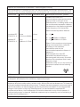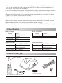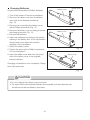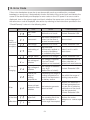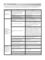
1
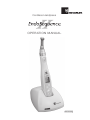
Cordless Handpiece OPERATION MANUAL OM-ER436E Thank you for purchasing the EndoSequence II. Read this Operation Manual carefully before use for operation instructions and maintenance guidelines. Keep this Operation Manual for future reference. Application This product is a cordless handpiece used primarily for root canal enlargement. User Only qualified personal is allowed to use the unit only for dentistry. Prohibition Do not use this motor handpiece in an extremely bent root canal. Do not use this for implants other than endodontic treatment or other dental treatment. Classification of Devices Classification by type of protection against electric shock: - Class II devices Classification by degree of protection against electric shock: - Applied part type B Classification by sterilization or disinfection method allowed by the manufacturer: - Refer to Sterilization. Classification by mode of operation: - Continuously operating device Guidance and manufacturer's declaration - electromagnetic emissions The EndoSequence II is intended for use in the electromagnetic environment specified below. The customer or the user of the EndoSequence II should assure that is used in such an environment. Emissions test Emissions test Electromagnetic environment - guidance RF emissions CISPR11 Group 1 The EndoSequence II uses RF energy only for its internal function. Therefore, its RF emissions are very low and are not likely to cause any interference in nearby electronic equipment. RF emmissions CISPR11 class B Harmonic emissions IEC61000-3-2 class A Voltage fluctuations/ flicker emissions IEC61000-3-3 Complies The EndoSequence II is suitable for use in all establishments, including domestic estabilishments and those directly connected to the public low-voltage power supply network that supplynetwork that spplies buidings used for domestic purposes. 1 Guidance and manufacturer's declaration - electromagnetic immunity The EndoSequence II is intended for use in the electromagnetic environment specified below. The customer or the user of the EndoSequence II should assure that it is used in such an environment. Immunity test IEC60601 test level Compliance level Electromagnetic environment - guidance Electrostatic discharge (ESD) IEC61000-4-2 ±6kV contact ±8kV air ±6kV contact ±8kV air Floors should be wood, concrete or ceramic tile. If floors are covered with synthetic material, the relative humidity should be at least 30%. Electrical fast transient/burst IEC61000-4-4 ±2kV for power supply lines ±1kV for input/output ±2kV for power supply lines Mains power quality should be that of a typical commercial or hospital environment. Surge IEC61000-4-5 ±1kV line(s) to line(s) ±1kV line to line ±2kV line(s) to earth ±2kV lines to earth Mains power quality should be that of a typical commercial or hospital environment. Voltage dips, short interruptions and voltage variations on power supply input lines IEC61000-4-11 <5% Ut (>95% dip in Ut) for 0.5 cycle 40% Ut (60% dip in Ut) for 5 cycles 70% Ut (30% dip in Ut) for 25 cycles <5% Ut (>95% dip in Ut) for 5 secs <5% Ut (>95% dip in Ut) for 0.5 cycle 40% Ut (60% dip in Ut) for 5 cycles 70% Ut (30% dip in Ut) for 25 cycles <5% Ut (>95% dip in Ut) for 5 sec Mains power quality should be that of a typical commercial or hospital environment. If the user of the EndoSequence II requires continued operation during power mains interruptions, it is recommended that the EndoSequence II be powered from an uninterruptible power supply or a battery. Power frequency (50/60Hz) magnetic field IEC61000-4-8 3 A/m 3 A/m Power frequency magnetic fields should be at levels characteristic of a typical location in a typical commercial or hospital environment. NOTE: Ut is the a.c. mains voltage prior to application of the test level. 2 Guidance and manufacturer's declaration - electromagnetic immunity The EndoSequence II is intended for use in the electromagnetic environment specified below. The customer or the user of the EndoSequence II should assure that it is used in such an environment. Immunity test IEC60601 test level Compliance level Electromagnetic environment - guidance Portable and mobile FRO communications equipment should be used no closer to any part of the EndoSequence II, including cables, than the recommended separation distance calculated from the equation applicable to the frequency of the transmitter. Recommended separation distance Conducted RF IEC61000-4-6 3Vrms 3Vrms 150 kHz to 80MHz Radiated RF IEC61000-4-3 3V/m 80MHz to 2.5 GHz d = 1.2 P d = 1.2 P 80MHz to 800MHz d = 2.3 P 800MHz to 2.5GHz 3V/m Where P is the maximum output power rating of the transmitter in watts (W) according to the transmitter manufacturer and d is the recommended separation distance in meters (m). Field strengths from fixed RF transmitters as determined by an electromagnetic site survey, should be less than the compliance level in each frequency range. Interference may occur in the vicinity of equipment marked with the following symbol: NOTE 1 At 80MHz and 800MHz, the higher frequency range applies. NOTE 2 These guidelines may not apply in all situations. Electromagnetic propagation is affected by absorption and reflection from structures, objects and people. a) Field strengths from fixed transmitters, such as base stations for radio (cellular/cordless) telephones and land mobiles radios, amateur radio, AM and FM radio broadcast and TV broadcast cannot be predicted theoretically with accuracy. To assess the electromagnetic environment due to fixed RF transmitters, an electromagnetic site survey should be considered. If the measured field strength in the location in which the EndoSequence II is used exceeds the applicable RF compliance level above, the EndoSequence II should be observed to verity normal operation. If abnormal performance is observed, additional measures may be necessary, such as reorienting or relocating the EndoSequence II. b) Over the frequency range 150kHz to 80MHz, field strengths should be less than 3 V/m. 3 Recommended separation distances between portable and mobile RF communications equipment and the EndoSequence II. The EndoSequence II is intended for use in an electromagnetic environment in which radiated RF disturbances are controlled. The customer or the user of the EndoSequence II can help prevent electromagnetic interference by maintaining a minimum distance between portable and mobile RF communications equipment (transmitters) and the EndoSequence II as recommended below, according to the maximum output power of the communications equipment. Rated maximum output power of transmitter W Separation distance according to frequency of transmitter m 150kHz to 80MHz d=1.2 P 80MHz to 800MHz d=1.2 P 800MHz to 2.5GHz d=2.3 P 0.01 0.12 0.12 0.23 0.1 0.38 0.38 0.73 1 1.2 1.2 2.3 10 3.8 3.8 7.3 100 12 12 23 For transmitters rated at a maximum output power not listed above, the recommended separation distance d in meters (m) can be estimated using the equation applicable to the frequency of the transmitter, where P is the maximum output power rating of the transmitter in watts (W) according to the transmitter manufacturer. NOTE 1 At 80 MHz and 800 MHz, the separation distance for the higher frequency range applies. NOTE 2 These guidelines may not apply in all situations. Electromagnetic propagation is affected by absorption and reflection from structures, objects and people. 4 CONTENTS Cautions for handling and operation - - - - - - - - - - - - - - - - - - - - - - 5 1. FEATURES - - - - - - - - - - - - - - - - - - - - - - - - - - - - - - - - - - - - - - - 8 2. SPECIFICATION - - - - - - - - - - - - - - - - - - - - - - - - - - - - - - - - - - - 9 3. Name of each part - - - - - - - - - - - - - - - - - - - - - - - - - - - - - - - - - 9 4. Parts and its function - - - - - - - - - - - - - - - - - - - - - - - - - - - - - - - - 10 5. Operations - - - - - - - - - - - - - - - - - - - - - - - - - - - - - - - - - - - - - - 13 6. Convenient Function - - - - - - - - - - - - - - - - - - - - - - - - - - - - - - - - 18 7. Cleaning - - - - - - - - - - - - - - - - - - - - - - - - - - - - - - - - - - - - - - - - 20 8. Sterilization- - - - - - - - - - - - - - - - - - - - - - - - - - - - - - - - - - - - - - - 21 9. Motor Cap - - - - - - - - - - - - - - - - - - - - - - - - - - - - - - - - - - - - - - - 21 10. Safety System - - - - - - - - - - - - - - - - - - - - - - - - - - - - - - - - - - - - - 22 11. Changing Batteries - - - - - - - - - - - - - - - - - - - - - - - - - - - - - - - - - 22 12. Error Code - - - - - - - - - - - - - - - - - - - - - - - - - - - - - - - - - - - - - - - 24 13. Troubleshooting - - - - - - - - - - - - - - - - - - - - - - - - - - - - - - - - - - - 25 14. Warranty - - - - - - - - - - - - - - - - - - - - - - - - - - - - - - - - - - - - - - - - 26 15. Disposigng Product - - - - - - - - - - - - - - - - - - - - - - - - - - - - - - - - - 26 Cautions for handling and operation Read these safety cautions thoroughly before use and operate the product properly. These indicators are to allow you to use the product safely and prevent danger and harm to you and others. These are classified by degree of danger, damage and seriousness. All indicators concern safety, therefore always follow them. Classification Degree of danger or damage and seriousness DANGER Explains an instruction where death or serious injury may occur. WARNING Explains an instruction where bodily injury or damage to device may occur. CAUTION Explains an instruction where possibility for minor to medium bodily injury or damage to device may exist. NOTICE Explains an instruction that should be observed for safety reasons. 5 DANGER • Use the specified batteries for this product. Never use any other batteries than those that BRASSELER USA specifies. • This product is designed specifically for use with rechargeable batteries. Do not use manganese or alkaline batteries. Using and charging these may cause a fluid leak or explosion. • Always replace both batteries with the same type at the same time. Using batteries of different-types or an exhausted battery with a fully charged one may cause a fluid leak or explosion. WARNING • This product is Medical Electrical equipment. EMC (Electromagnetic compatibility) is described in the accompanying documentation. • Portable and mobile RF communications equipment can affect Medical Electrical equipment. Do not use RF equipment outskirts for the product. • If the handpiece has not been used for long period of time, check before use to ensure proper performance. • Do not handle the power cord with wet hands. Failure to do so may result in an electric shock. • Do not spill water or a chemical solution onto or into the motor handpiece or battery charger. Failure to do so may result in fire or electric shock due to a short-circuit or breakage due to rust formation. • Do not disassemble or alter the motor handpiece except to replace batteries. • Do not drop the motor handpiece or battery charger. Place the battery charger on a flat and stable surface. • Should the battery fluid leak and get into your eyes, immediately wash eyes thoroughly with clean water and see your doctor. Failure to do so may result in loss of sight. • Should the battery fluid leak and adhere to skin or clothing, immediately wash the exposed skin thoroughly with clean water and completely wash away the fluid. Failure to do so may result in skin irritation. • If you notice a battery fluid leak within the motor handpiece, deformation of the motor handpiece casing or partial discoloring, immediately stop use and contact Brasseler USA. • If you will not use the product for a long period of time, remove the batteries to avoid a fluid leak. • Do not charge the handpiece without battery. • Be careful not to drop conductive parts such as wires and safety pins into the charging terminal area of the battery charger. • To charge the motor handpiece, only use a dedicated genuine BRASSELER USA charger. Never charge this handpiece with a charger other than the genuine BRASSELER USA charger. When inserting the motor handpiece into the charger, check that the alarm sounds and the LED indicate charging (animation for remaining battery capacity). Unless charging is indicated, this function is not performed and burns may result by heat generation or liquid leakage may result, therefore, stop use and contact Brasseler USA. 6 • The motor handpiece has an electronic circuit (TORQUE LIMITER Function) to prevent files from breaking; however, files may still break due to metal fatigue if the torque is conditioned to be higher. CAUTION • Exercise sufficient care in using the product by giving patient safety first priority. • The product is to be used for dental treatment only by qualified personnel. • Use commercially available batteries as specified by BRASSELER USA. Read the instruction manual included by the battery manufacturer thoroughly before use. • Do not use a bent, damaged, deformed or non-ISO-conforming file. Using such a file may result in personal injury due to its sudden breakage or coming loose during rotation. • Do not use or leave the product in a high-temperature environment such as under strong direct sunlight, in a car under a blazing sun, by a fire or near a stove. • Check the product before use, pay attention to looseness, vibration, noise and temperature (heat generation). If any abnormal condition is found even slightly at that time, immediately stop use and contact Brasseler USA. • Always clean the shank of the file to be installed. Allowing dirt to enter the chuck could cause loss of concentricity and deterioration of chucking force. • Before changing the head or file, turn off the power of the motor handpiece. Changing with the power on may cause unintended rotation by accidental activation of the ON/OFF switch. • When inserting the motor handpiece into the battery charger, position the handpiece correctly. Pushing it into the charger forcibly in the incorrect orientation may cause damage. • Do not lubricate the motor handpiece. Only lubricate the head attachment. • Do not heat sterilize the motor handpiece. Do not autoclave the motor handpiece. • If you are using corrosive or harsh solutions please clean the motor handpiece etc., immediately after use. Failure to quickly clean the motor handpiece etc., can result in damage to the equipment or color changes of the outer casing. • Do not reverse positive (+) and negative (-) when fitting the batteries. • Do not throw the batteries into fire as the batteries will rupture, resulting in an accident. • This equipment is for indoor use only. • Observe the allowable rotation speed recommended by the file manufacturer. 7 NOTICE • This product does not consider patient’s age (except infants), gender, weight or nationality. • The motor handpiece is designed for commercially available AAA nickel metal hydride batteries (rechargeable). Ni-Cad batteries can also be used, but the charging time and operating time become significantly shorter since the charging current differs. • The motor handpiece consumes electricity very slightly even when the power is off. In addition, fully-charged rechargeable batteries, in general, discharge gradually over time even though it is not used. It is recommended to recharge the batteries just before use. • When the motor handpiece automatically stops by detecting a low battery voltage, leaving it for a while and turning on the power again may not detect the low voltage immediately. This is not a failure, but due to battery characteristics. The voltage drop does not coincide with the remaining battery capacity. • Recharge rechargeable batteries after they deplete as much as possible. Repeating short time use and subsequent recharging may shorten their operating time due to a “memory effect.” Batteries may recover from the memory effect after fully discharging and then fully charging and repeating this procedure a few times. • Eventually completely discharged batteries cannot be charged and need to be replaced. • User shall be responsible for operation, maintenance and operation. • No special training is required for this device. Symbols TUV Rhineland of North America is a Nationally Recognized Testing Laboratory (NRTL) in the United States and is accredited by the Standards Council of Canada to certify electro-medical products with Canadian National Standards. Follow the waste of electric and electronic equipment (WEEE) Directive (2002/96/CE) to dispose of the product and accessories. Class II equipment Type B conforming component Refer to the Operation Manual. A manufacturer's name and address 1. Features • Ergonomic design and compact body. • “6 position type head” allows direction of contra angle head to be changed and the ON/OFF key to be set to a position where it can be easily activated. • The larger ON/OFF key enhances operability (compared with conventional products). • Operates continuously for approx. 1.2 hour at rated load. (Dependent upon use conditions.) • The liquid crystal panel enhances ease of use. • Memory for up to 5 programs . • The auto reverse function is activated depending on the load. A wide variety of functions such as “AUTO REVERSE”, “AUTO STOP” and “AUTO REVERSE OFF” are available. The memory can store these functions combined with nine different operation programs. 8 • The motor handpiece can be turned on and off by pressing the ON/OFF key. Alternatively the unit can be operated by holding down the ON/OFF key during operation and letting go of the ON/OFF key to stop the handpiece. • The motor handpiece softly starts. Since the rotation briefly stops before changing direction there are no vibrations and shocks during the change of directions. • Energy saving. The power of the motor handpiece automatically turns off when not being used for 10 minutes. (Auto power-off function) • The built-in feedback circuit, which keeps rotation at a constant speed even when the load on the motor handpiece changes. • Non-contact charger prevents improper charging due to deterioration of metallic terminal. • Rapid Charging feature shortens the time needed for battery charging. • The contra angle heads provided for this product are all autoclavable at 135ºC (excluding the motor handpiece). 2. Specification Battery Charger Model Input Voltage Input Power Charging Time Motor Handpiece Model Input Voltage Input Power NE263 AC120/240V±10% 50/60Hz 15VA Approx. 90 min. SQ10M2 DC2.4V±20% 0.3VA Use environment Store environment Temperature Humidity Temperature Humidity 10 - 40 ˚C (32º-104ºF) 10 - 75 % (Non condensing) Atmospheric pressure 500-1060 hPa -10 - 50 ˚C (14º-122ºF) 10 - 80 % (Non condensing) Atmospheric pressure 500-1060 hPa 3. Name of each part Battery charger Motor Handpiece F-type spray nozzle Contra Angle Handpiece 9 Power cord Motor cap 4. Parts and its function <Operation Panel Details> <LCD Panel> ON/OFF Key Program No. Speed* Torque Auto Reverse mode LCD Panel Buttery Symbol Alarm Symbol *Speed = Rotation speed of the file Gear ratio SELECT Key PROGRAM Key UP Key DOWN Key Power Key <Operation Panel Details> • POWER Key (Torque setting screen) (Gear ratio setting screen) - Holding down the POWER key for more than one second turns on the power and the LCD panel lights. - Holding down the POWER key for more than one second while the power is on turns off the power and the LCD display turns off. • ON/OFF Key Pressing this switch, when the power is on, rotates the motor handpiece, and de-pressing the switch again stops the handpiece. (Normal rotation operation) Pressing and holding the switch for approx. one second or longer rotates the motor handpiece and releasing the switch stops the handpiece. (Temporary rotation operation) • SELECT Key Press the SELECT key to change speed, torque or gear ratio setting. Select the parameter for which you want to adjust the set value. The following parameters can be changed in the following order: speed (SP) torque (TQ) gear ratio (GR). However, gear ratio cannot be set during rotation of handpiece. Pressing and holding this SELECT Key for 1 second or longer, when the motor handpiece is stopped can change the Auto reverse mode. (See Auto Reverse) 10 NOTICE • If the speed or torque set value has reached the upper limit or lower limit when the gear ratio has been changed, the alarm sounds. • The indication of “ ” for torque setting is the upper limit value of torque. If you attempt to set torque which exceeds this value, the alarm sounds. • The speed can be set at any time if it is normally indicated. • PROGRAM Key A program can be selected. The present program number is displayed. There are 5 programs available, numbered from 1 to 5. Up to five programs can be set, and program settings can be memorized by pressing this key for one second or longer. The following parameters can be set: Speed, Torque, Gear Ratio and Auto Reverse setting. • UP/DOWN Key Use this key when adjusting the set value for each parameter. Alarm sounds if the set value exceeds the upper limit or lower limit. Unit to be set is min-1 for speed and N·cm for torque. Set torque suitable for contra angle which you use. For gear ratio, 4:1, 10:1, 16:1 or 20:1 can be set. <LCD Panel> • AUTO REVERSE The current auto reverse mode mark is displayed. AUTO REVERSE: If the load is removed after auto reverse rotation, it returns to the normal rotation again. AUTO STOP: If the load is removed after auto reverse rotation, it stops. AUTO REVERSE OFF: Auto reverse rotation is not activated. 11 • BATTERY Symbol The symbol indicating the battery status is displayed regardless of the ON or OFF position of the power. The symbol will be animated when the batteries are being charged or in the refresh mode : Full charge or nearly full charge : About 30-80% remains : Less than about 30% remains : Batteries are drained or in a remarkably low voltage. Charge the batteries. NOTICE The symbol indicating the remaining amount of the batteries indicates a voltage. When load is applied to the motor handpiece, the symbol indicating the remaining amount of the battery charge may appear to be lower. • ALARM Symbol The present alarm symbol is displayed. : Alarm ON No Display : Alarm OFF(No display) NOTICE Load alarm when the motor rotates and auto reverse sound can be set to ON/OFF. (Refer to 6 (3) Alarm Sound Volume Control) 12 5. Operations (1) Charging Batteries 1. Insert the Power Cord Jack into the inlet at the back of the Battery Charger. (Fig. 4) 2. Insert the Power Cord and Plug in. Make sure you have the correct voltage. 3. Turn on the Power Switch. At this time, check that the power lamp lights up. (Fig. 5) 4. Insert the motor handpiece into the Battery Charger. Charging starts with the charge mark flashing on LCD screen. 5. When the alarm sounds and “ ” is displayed on the LCD panel, charging is completed. Power Cord Jack Power Switch Inlet Power Lamp Fig. 4 Fig. 5 WARNING When the alarm does not sound and the charging animation is not displayed despite batteries being replaced with new ones, immediately stop using and contact Brasseler USA. (Refer to Changing Batteries) 13 CAUTION • When the power lamp for the charger does not light up, the internal fuse may be faulty. In this case please contact Brasseler USA. • Be careful when placing the motor handpiece in to the charger. Do not force the handpiece into the charger. Otherwise, failure may occur. • If the power cord is inserted into the jack or the power switch is pressed with unnecessary force, the cord or switch may be broken or a short-circuit may occur. • Never use the battery charger for anything other than the motor handpiece of this product. • The charging normally takes approx. 90 minutes, but it depends on battery use conditions, battery freshness, ambient temperature, etc. Older batteries are especially prone to significantly shorter charging and operating times. • Batteries may slightly warm up during charging, but this is normal. If the handpiece is inserted or removed into/from the charger at short intervals, (approx. 5 minutes) charging cannot be properly completed and the battery compartment may feel hot. We recommend that you charge batteries for longer periods if possible. • The power of the motor handpiece should not be turned on immediately after it has been removed from the charger, wait at least approx. 2 seconds before you switch on the power. • Completely discharged batteries cannot be charged. Replace them with new ones. • Do not put anything (metal or other devices such as wire, safety pin, or coin) other than the handpiece on the charger. Otherwise, burn or failure may result due to heat generation. • The temperature of the batteries is measured during charging. Proper charging cannot be performed if the charger is placed in an environment which is subject to sharp temperature change (next to window, subject to direct sunlight, near air outlet or fan heater). Place it in a location where temperature change is minimal. • Charging may not start in the following case. The temperature of the batteries is excessively high or low. (Lower than approx. 0°C or higher than approx. 40°C) Battery voltage is sufficient Battery voltage is abnormal 14 (2) Changing Contra Angle Head Positioning pin The contra angle head can be connected with the motor handpiece at 6 adjustable head positions. Align the positioning pins of the contra angle head with the positioning slots of the motor handpiece and insert the head until they click. When removing the contra angle head, pull it straight out. Contra angle head Positioning groove Motor handpiece Fig. 6 CAUTION • Turn OFF the power to remove or attach the contra angle head. • Check that the contra angle head is securely connected to the motor handpiece. (3) Mounting and Removing File Insert file to contra angle head, lightly turn the file until it engages with the latch mechanism. Push it inward to click. (Fig. 7) File Removal, depress the push-key and pull out the file. (Fig. 8) Fig. 7 Fig. 8 CAUTION • When attaching and detaching the file, turn off the power beforehand. • After the file is locked in place, lightly pull out the file to make sure the file is locked. • Always clean the shank of the file to be installed before use. Allowing dirt to enter the chuck could cause loss of concentricity and deterioration of chucking force. • Do not exceed the rotation speed recommended by the file manufacturers. 15 <Operation Panel> (4) Preparatory Operations 1. Hold down the POWER key for more than one second to turn on the power. 2. Press the PROGRAM key until program No. suitable for file to be used is displayed. 3. When changing the set value of Speed, Torque, Gear Ratio or Auto Reverse, press the SELECT key, select the setting item and press the UP/DOWN key to change. ON/OFF key Liquid crystal panel NOTICE The GEAR RATIO key is Fast-Forwarded, when it is continuously held down. (5) Operation SELECT key PROGRAM key UP key DOWN key POWER key If you press the ON/OFF key briefly, the motor handpiece starts. If you re-press the key, it stops. (Alternate operation) If you hold down the ON/OFF key for more than one second, the motor handpiece starts while the key is pressed. If you release the key, it stops. (Intermittent operation) Auto Reverse Function Auto reverse setting can be changed by pressing the SELECT key for one second or longer while the motor handpiece stops. As the auto reverse mark flashes while the SELECT key is kept pressed, press the UP/DOWN key to adjust it. : Auto Reverse : Auto Stop : Auto Reverse OFF (flashes while the SELECT key is kept pressed, and goes out when it is released) The alarm will sound when it becomes a value of half of a torque limit set up during motor handpiece rotation, and the alarm will change near the torque limit value. (Load alarm) When it continues applying a load and it exceeds the torque limit value you can select mode from the following three modes. 16 AUTO REVERSE The handpiece starts in forward rotation. When a load higher than the torque limit is applied, the file will rotate in reverse. When the load is removed, the file will return to normal rotation (forward) automatically. Load lower than the set torque limit value Load higher than the set torque limit value Reverse rotation when load continues, forward rotation when load is removed Forward rotation Reverse rotation Returns to forward Fig. 9 AUTO STOP The handpiece starts in forward rotation. When a load higher than the torque limit is applied, the file will rotate in reverse. When the load is removed, the motor rotation stops. If you want it to rotate again, re-press the ON/OFF Key. Load lower than the set torque limit value Load higher than the set torque limit value Forward rotation Reverse rotation Reverse rotation when load continues, stop when load is removed Stop Fig. 10 AUTO REVERSE OFF The motor handpiece stops without reverse rotation. If you want it to rotate (forward-rotate) again, re-press the ON/OFF Key or re-step. CAUTION • When the battery charge is low, the actual load may not reach the preset torque limit value. In this case the auto reverse function will not be activated. • If a load is continuously applied to the motor handpiece, it may automatically stop to prevent overheating. In this case, let the motor handpiece cool down. • If the ambient temperature is low, the alarm may sound when the motor handpiece rotates, however, this is not a failure. If the alarm does not stop sounding even when the ambient temperature increases, clean the contra angle head and perform calibration. (Refer to 6 (2) Calibration) 17 (6) Completion of Medical Treatment When the treatment is completed, hold down the POWER key for more than one second to turn off the power and return the motor handpiece to the handpiece stand Auto Power Off If the handpiece is not operated or approximately 10 minutes passes during rotation with no-load, the power is automatically turned OFF to save energy and prevent improper operation. However, if load is applied during rotation of the motor handpiece, the power is not turned OFF even during no operation. LAST SETTING When the power is turned OFF the last setting used is memorized. When the Power is turned back ON, the most recent settings will appear. 6. Convenient Function (1) Program You can change any preset values and have them memorized to your desired settings (rotation speed, torque limit value, gear ratio and auto reverse mode) 1. Press the PROGRAM key until it turns to the program number which you want to have memorized. 2. Adjust the rotation speed, torque limit value, gear ratio and auto reverse mode by UP/DOWN key according to your needs. 3. Hold down the PROGRAM key for more than one second. When the alarm sounds the settings have been memorized. NOTICE • The program cannot be memorized while the motor handpiece is in motion. • The program is not memorized unless the PROGRAM key is held down for more than one second. If the program number is changed by the PROGRAM key, the initially memorized preset values remain. (Cancel function) (2) Calibration This function is to decrease fluctuation in the rotation speed of the motor handpiece and the difference in torque by the contra angle head. 1. Lubricate the contra angle head with BRASSELER USA SPRAY). (Refer to the “7 (1) Lubricating Contra Angle Head.”) 2. Turn on the power. 3. Hold down UP/DOWN key simultaneously for more than one second. 4. The LCD panel displays “ ” with the alarm sound. 5. Attach the contra angle head to the motor handpiece and press the ON/OFF key. (Remove the file or TEST bur.) 6. If the motor handpiece begins to rotate, leave it as it is until it stops. 7. This process ends, if the rotation stops and the LCD panel display returns to its original state. 18 8. If you want to stop this process, turn off the power. NOTICE • This function does not work unless remaining battery capacity is sufficient. • Perform calibration after cleaning the contra angle head. Residual contamination on the rotating shaft will impair correct measurement. • Do not touch or apply a load to the rotating shaft of the contra angle head. It will obstruct accurate measurement. • This function cannot completely detect the individual difference of the actual motor handpiece and contra angle head. (3) Alarm Sound Volume Control 1. Setting alarm sound You can turn ON/OFF the alarm (load alarm) which sounds near the torque limit value when the motor handpiece rotates and the alarm during auto reverse (auto reverse sound). 1. Turn off the power 2. While pressing SELECT key, keep pressing POWER key one second or more. 3. The alarm mark and ON or OFF on the LCD panel. 4. Press the SELECT key to select ON or OFF for alarm sound. 5. Display on the liquid crystal panel (LCD) returns to the original state if no operation is performed for a while. NOTICE The volume setting is memorized automatically to the last setting and remains unchanged even if the power is turned off. 19 7. Cleaning (1) Lubricating Contra Angle Head • Lubricate the contra angle head only. • Apply SPRAY after each use and/or before each calibration and autoclaving 1. Lubricate before each autoclaving or once a F type spray nozzle day if you do not autclave, using SPRAY Contra angle head lubricant. Secure the F type spray nozzle onto the Spray nozzle. 2. Insert the F type spray nozzle into the rear part of the contra angle head and lubricate the head for 2-3 seconds. If the handpiece does not push into nozzle enough, oil may not go around into the handpiece and it may flows backward. (2) Cleaning Motor Handpiece When the motor handpiece becomes dirty, wipe it off with a cotton cloth moistened with rubbing alcohol. (3) Cleaning Charger When the charger becomes dirty, wipe it off with a cotton cloth moistened with isopropyl alcohol. CAUTION • Do not lubricate the motor handpiece. • Before mounting the lubricated contra angle head to the motor handpiece, wipe off excess oil. Stand it on its end or lean it in the proper position for gravity draining. Mount it after excess oil has been completely drained. • Hold the contra angle head securely to prevent it from flying off by the pressure of the spray. • Hold the spray can upright. • When cleaning the motor handpiece, do not use any solvent such as benzene and, thinner. 20 SPRAY Fig. 11 8. Sterilization Sterilize the contra angle head only. For the sterilization method, we recommend autoclaving. Autoclave sterilization required the first time you use and after each patient as noted below. Autoclaving 1. Brush the dirt off the surface of the contra angle head, and wipe it off with a cotton cloth moistened with isopropyl alcohol. Do not use a metal brush. 2. Lubricate the head with the SPRAY. 3. Insert the head into an autoclave pouch and seal it. 4. Autoclavable up to a max. 135°C (275°F). ex.) Autoclave for 20 min. at 121°C (250°F), or 15 min. at 132°C (270°F). 5. Keep the handpiece in the autoclave pouch to keep it clean until you use it. * Sterilization at 121°C for more than 15 minutes is recommended by EN ISO 17665-1 CAUTION • Do not autoclave the motor handpiece. • Since the lowermost tray inside the chamber of the autoclave is close to a heater and the temperature in that place may locally exceed 135°C (275°F), place the head on the central or upper tray. • Do not wipe with, or clean or immerse in, high acid water or sterilizing solutions. 9. Motor Cap When the contra angle head is removed from the motor handpiece for battery charging, lubrication, or sterilization, mount the motor cap onto the motor handpiece to prevent debris from entering. Motor Cap Motor Handpiece Fig. 12 21 10. Safety System The motor handpiece monitors temperature of the batteries. If the batteries become abnormally hot, this system functions and the motor handpiece automatically stops. In such a case, wait until the motor handpiece cools down sufficiently. If this safety system functions repeatedly, either the batteries or motor handpiece is not in the normal operating condition and you should contact Brasseler USA. 11. Changing Batteries The motor handpiece uses rechargeable batteries. They can be recharged 300-500 times, depending on the use conditions of the motor handpiece. If the operating time becomes shorter or the rotation speed becomes slower, although the “MEMORY EFFECT” described in “ NOTICE” is not applicable, the batteries may be at the end of their life expectancy. In such a case, ask Brasseler USA to replace the batteries or replace them with new ones yourself. (Refer to the “ Changing Batteries.”) When replacing them by yourself, be sure to observe the following “ CAUTIONS ON CHANGING BATTERIES.” Please note that BRASSELER USA shall not be liable for any malfunction or failure resulting from you changing the batteries yourself and not following the “ CAUTIONS ON CHANGING BATTERIES.” CAUTIONS on CHANGING BATTERIES • Do not open any part other than the battery cover. • Use only batteries as specified by BRASSELER USA. • Designated Batteries : AAA (marking may be different) nickel metal hydride batteries, nominal 1.2 V • Do not use non-charging type batteries such as alkaline batteries and manganese batteries. Charging with these batteries may cause fluid leaks, explosion or chlorine gas generation. • Should the battery fluid leak and get into your eyes, immediately wash thoroughly with clean water and seek medical attention. • Should the battery fluid leak and adhere to skin or clothing, immediately wash the exposed skin thoroughly with clean water and completely wash away the fluid. Failure to do so may result in a skin irritation. • Always replace two batteries of the same type by the same manufacturer at the same time. Using batteries of different-types, an exhausted battery with a fully charged one, or a new battery with an old one may cause a fluid leak or explosion. • Do not work with wet hands. Failure to do so may result in rust formation on battery terminals or moisture intrusion inside, and could cause failure of the product. 22 Changing Batteries Rubber Cover Battery Cover Prepare small screwdrivers (Phillips, flathead). 1. Turn off the power of the motor handpiece. 2. Remove the rubber cover from the battery cover with a thin flathead screwdriver. (Fig. 13) 3. Remove the screw fixing the battery cover with a Phillips screwdriver. (Fig. 14) 4. Remove the battery cover by sliding it toward the charging terminal. (Fig. 15) 5. Remove old batteries. 6. Insert new batteries according to the polarity marking in the battery box. A mix-up between the plus and minus sides will not allow operation of the handpiece. 7. Attach the battery cover. 8. Tighten the screw with a Phillips screwdriver. Do not overtighten it. 9. Insert the rubber cover back into the screw hole of the battery cover in the originally inserted direction. Fig. 13 Battery Cover Screw Fig. 14 Battery Cover Changing of batteries is now completed. Charge them fully before use. Fig. 15 CAUTION • Do not misplace the rubber cover and screw. • The used nickel metal hydride batteries are recyclable, but their disposal may sometimes not be permitted by local laws. 23 12. Error Code If the motor handpiece stops due to an abnormality such as a malfunction, overload, breakage or wrong use, it automatically checks the state of the control unit and detects the cause of the abnormality and displays an error code on the LCD panel. If an error code is displayed, turn on the power again and check whether the same error code is displayed. If the same error code is displayed, take action by referring to the instructions provided in the “Check/Remedy” column in the following table. Error code During rotation of the motor handpiece At the time of Charging Other At the time of calibration Error Cause Check/Remedy Self-Check error Malfunction of circuit Overcurrent The motor handpiece is locked. (at the time of Remove load the auto reverse mode) Overvoltage Malfunction of circuit Overheating of motor High load was continuously applied to Leave it as it is until it the motor handpiece cools down. for a relatively long time. Charger failure Malfunction of charger Low voltage of batteries The voltage of batteries Put the batteries into the is too low (“dead” battery chamber, or batteries or not inserted.) replace with new batteries. High voltage of batteries The voltage of batteries is too high. Contact Brasseler USA. (Malfunction of circuit) Outside the range of working temperature Outstanding the range of working temperature or Use within the range of break in the thermistor in working temperature. the battery section Abnormal heat The batteries generate generation from abnormal heat. batteries Beyond the upper limit Contact Brasseler USA Contact Brasseler USA Contact Brasseler USA Replace the batteries. If the heat generates from the new set of batteries, malfunction of the circuit may be suspected. Contact Brasseler USA. The operating life of the Replace the motor handpiece or contra angle motor handpiece or Below the lower contra angle has expired head. limit 24 13. Troubleshooting If you experience a problem, please check the following again before consulting Brasseler USA. If the problem cannot be remedied, please contact Brasseler USA. Contact Brasseler USA. Problem The power is not turned on. Cause Solution Batteries have fully discharged. (Has the handpiece been left with batteries inserted for a long time?) Recharge the batteries. If battery does not fully discharge, charge will start. If the batteries are fully discharge,replace with new batteries No batteries are inserted. Insert batteries. The internal fuse has burnt. Contact Brasseler USA. Batteries have been completely discharged. Replace with new batteries. The temperature of batteries is low. The battery charger does not work. (The CHARGE animation does not display) The battery charger does not work. (the power for the charger is not turned ON) If the temperature of batteries is less than 0°C (32°F), the batteries cannot charge. Charge the batteries in a warm room. (Be careful about moisture condensation.) The temperature of batteries is high. If the temperature of batteries is more than 40°C (104ºF), the batteries cannot charge. Charge within the range of working temperature. It is normal that the batteries become a little bit warm right after charging. If the batteries are hot under normal operating conditions, not right after charging, there may be an abnormality. Contact Brasseler USA. The voltage of a battery is too high Check that no battery other than Ni-MH battery is used. The motor handpiece is not correctly set to the charger. Correctly set. Metal such as wire or safety pin is placed on the charger. Remove metal on the charger. An error code is displayed. See 12. Error Code. The power cord plug is not inserted into the outlet. Insert the power cord plug into the outlet. The power cord jack is not inserted into the inlet on the charger. Insert the power cord jack into the inlet on the charger. The power for the charger is OFF. Turn ON the power for the charger. The fuse has burnt. Contact Brasseler USA. 25 The motor handpiece set in the charger abnormally gets hot. If nothing is displayed on the liquid crystal panel of the handpiece Contact Brasseler USA. even when it is set in the charger, failure in the circuit is predicted. The motor The contra angle head has handpiece does jammed up. not rotate. Clean or replace the contra angle head. Power from the motor handpiece Batteries are weakened (lower remaining battery capacity) is weaker than usual. Charge the batteries. The Auto Reverse does not work. Batteries are weakened (lower remaining battery capacity) Charge the batteries. Rotation speed of the motor handpiece is lower. Batteries are weakened (lower remaining battery capacity) Charge the batteries. The ambient temperature is low. Use in a warm room. The alarm sounds when the motor handpiece is rotated. There is some residual contamination on the rotating shaft Clean the contra angle head. of the contra angle head. 14. Warranty Brasseler USA warrants the handpiece against defects in manufacturing, workmanship and materials. Brasseler USA reserves the right to analyze and determine the cause of any problem. Warranty is voided should the handpiece not be used in accordance with this manual. Batteries etc., are disposable components, and are not covered by this warranty. 15. Disposing Product • Please consult with Brasseler USA from whom you purchased regarding waste disposal. • The used nickel metal hydride batteries are recyclable, but their disposal may sometimes not be permitted by local laws. 26 By Your Side in Dentistry One Brasseler Boulevard, Savannah, GA 31419 To order call 800.841.4522 or fax 888.610.1937. Visit our website: www.BrasselerUSA.com ’08.00.00 N