1
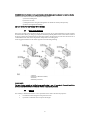
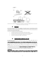
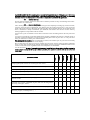
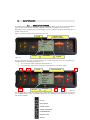
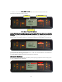
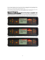
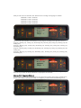
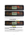
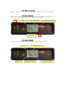
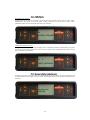
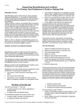
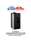
INSTALLATION AND USER’S MANUAL MOD. OMEGA HYDRO. “TECNOLOGÍA OASYS (Optimum Air System)”. Please read carefully these instructions before installation, use and maintenance. The instructions guide is an integral part of the product. 1 INDEX OF CONTENTS 1. GENERAL WARNINGS ………………………………………………………………………………………………………………………………….………………………………………….3 2. FUELS…………………………..…………………………………………………………………………………………………………………………………………………………………………...3 3. SAFETY DEVICES………………………………………………………………………………………………………………………………….…………..………………………………………..4 4. TECHNICAL FEATURES……………………………………………………………………………………………………………………………………..……………………………………….. 5 5. INSTALLATION REQUIREMENTS……….……………………………………………………………………………………………………………………….………………………………. 6 5.1. Safety measures……………………………………………………………………………………………………………………………………………………………………………..……. 6 5.2. Beams protection…………………………………………………………………………………………………………………………………………………………………………….……7 5.3. Chimney……………………………………………………………………………………………………………………………………..…………………………………………………… …… 7 5.4. Chimney cowl………………………………………………………………………………………………………………………………..………………………………………………….… 8 5.5. Connection to chimney / intake)……………………………………………………………………………………………………………….…….8 Combustion air (air 5.6. Outside air intake………………………………………………………………………………………………………………………………………………………………………..…….….9 6. 7. 8. 9. 10. HIDRAULIC INSTALLATION ........................................................................................................................................................................................................ 13 STARTING UP ................................................................................................................................................................................ ¡Error! Marcador no definido. USUAL OPERATION...................................................................................................................................................................................................................... 15 MAINTENANCE AND CARE ........................................................................................................................................................................................................ 15 9.1. Burner cleaning.................................................................................................................................................................................................... 15 9.2. Use of scrapers...................................................................................................................................................................................................... 15 9.3. Ash pan cleaning ............................................................................................................................................ ¡Error! Marcador no definido. 9.4. Ash pan and burner door joints ..................................................................................................................................................................... 15 9.5. Chimney cleaning................................................................................................................................................................................................ 15 9.6. Glass cleaning ....................................................................................................................................................................................................... 15 9.7. Exterior cleaning .................................................................................................................................................................................................. 16 9.8. Seasonal shutdowns........................................................................................................................................................................................... 16 DISPLAY OPERATION ................................................................................................................................................................................................................... 17 10.1. Display general information ............................................................................................................................................................................ 17 10.2. Display keys’ fuction ........................................................................................................................................................................................... 18 10.3 Remote control general information………………………………………………………………………………………………………………………….……………18 10.4. Menu option .......................................................................................................................................................................................................... 19 10.4.1. User Menu………………………….…… ............................................................................................................................................................................ 20 10.4.2. Menu 1. Clock……………………… ................................................................................................................................................................................ 20 10.4.3 Menu 2. Program Adjustemets…….. .................................................................................................................................................................... 20 10.4.4. Menu 3. Language selection…….. ....................................................................................................................................................................... 20 10.4.5. Menu 4. Stage/winter mode ............................................................................................................................................................................... 26 10.4.6. Menu 5. Stand-by mode….. ................................................................................................................................................................................... 26 10.4.7. Menu 6. Sonorous Mode ...................................................................................................................................................................................... 27 10.4.8. Menu 7. Initial Charge…. ....................................................................................................................................................................................... 27 10.4.9. Menu 8- Stove Stage………...................................................................................................................................................................................... 27 10.5. User Mode .............................................................................................................................................................................................................. 28 10.5.1. Starting up the stove….….... ................................................................................................................................................................................... 29 10.5.2. Operation stove…………… ........................................................................................................................................................................................ 29 10.5.3. Consigned room temperature changing........................................................................................................................................................ 30 10.5.4. Consigned water temperature changing ....................................................................................................................................................... 30 10.5.5. User fixed temperature reached by the room temperature … ................................................................................................................ 30 2 10.5.6. User fixed temperature reached by the water temperature… ................................................................................................................ 31 10.5.7. Burner cleaning………………. .................................................................................................................................................................................... 31 10.5.8, Shutdown the stove…… …… .................................................................................................................................................................................. 32 10.5.9. Stove switched off ……………................................................................................................................................................................................... 32 10.5.10. Re-starting up stove.............................................................................................................................................................................................. 33 10.6. What happens if …? ............................................................................................................................................................................................ 33 10.6.1. Pellet fuel does not light … ................................................................................................................................................................................... 33 10.6.2. Electrical supply failure (Back out)..................................................................................................................................................................... 34 10.7. Alarms ...................................................................................................................................................................................................................... 34 10.7.1. Smokes temperature probe alarm. .................................................................................................................................................................... 34 10.7.2. Smoke excess temperature alarm. ..................................................................................................................................................................... 35 10.7.3. Starting up failure alarm........................................................................................................................................................................................ 35 10.7.4. Shutdown during work phase alarm ............................................................................................................................................................... 35 10.7.5. Safety pressureswitch alarm …………... ................................................................................................................................................................ 36 10.7.6. Damaged extraction smokes fan alarm........................................................................................................................................................... 36 11. GENERAL MEASURES................................................................................................................................................................................................................... 35 3 1. GENERAL WARNINGS The stove installation has to be carried out in accordance with the local and national regulations, including all regulations referred to national or European standards. All stoves produced in our company are made controlling all the pieces and trying to protect both the user and the installer, in order to avoid possible accidents. We also recommend to the authorized technical installer, to pay special attention to electrical connections every time they carry out an operation, especially to the bare part of cables, which should never be out of the connections box so that dangerous contacts are avoided. The installation must be executed by authorized personnel, whose will have to give the buyer an installation declaration of conformity in which he assumes full responsibility for the definitive installation and for the correct operation of the installed product. Bronpi Calefacción S.L. will not assume any responsibility in case of non-fulfilment of these precautions. The manufacturer will be exempted from any responsibility owing to damages caused to third parties due to an incorrect installation or a bad use of the device. The components should only be replaced by original spares parts by an authorized technician in order to guarantee an accurate operation of the appliance. The maintenance of the device must be carried out at least once a year, by the Authorized Technical Service. For added security it is necessary to bear in mind: Don’t touch the stove if you are barefooted or have some parts of your body which are damp. The door of the unit must be closed during the operation. It is forbidden to modify the safety devices or regulations of the unit without the authorization of the manufacturer. Avoid direct contact with the parts of the appliance that tend to reach high temperatures during the operation. 2. FUELS WARNING!!! USING A BAD QUALITY PELLET FUEL OR ANY OTHER MATERIAL DAMAGES THE OPERATION OF THE STOVE AND COULD DETERMINE THE EXPIRATION OF THE WARRANTY IN ADDITION TO THE EXEMPTION OF RESPONSIBILITIES OF THE MANUFACTURER. Pellet fuel used has to be in accordance with the characteristics described in the norms: Ö-Norm M 7135 DIN plus 51731 UNI CEN/TS 14961 Bronpi Calefacción recommends using pellet fuel 6 mm in diameter and 3.5 cm long at the most. • PELLET FUEL STORAGE It is necessary to preserve the pellet fuel on a dry environment in order to avoid combustion problems • PELLET FUEL SUPPLY For supplying the stove, open the hopper lid at the top of the appliance pouring directly into it the pellet fuel, taking care not to overfill the hopper. 3. SAFETY DEVICES • IGNITION FAILURE If during the ignition stage the flame does not take place, the appliance will show in the display “no ACC”. If you try to light the machine again, in the display you will read “ATTE“which means “wait“. This function serves to remember that, before carrying out an ignition, it is necessary to verify that the burn pot is completely clear and clean. 4 • BREAKDOWN OF THE WARM AIR DISTRIBUTION FAN In case that ventilation stops for any reason, the stove stops automatically so that it avoids the overheating (not included on hydro models). • BREAKDOWN OF THE SMOKE VACUUM CLEANER If the extractor stops, the electronic card blocks automatically the pellet fuel supply. • BREAKDOWN OF THE PELLET FUEL LOADING ENGINE If the differential engine stops, the stove keeps on working until it reaches the minimal functioning temperature and stops. • ELECTRIC CURRENT TEMPORARY FAILURE After a brief lack of current, the stove turns on again. When electricity is missing, the stove can produce a limited quantity of smoke inside the house during an interval of 3 to 5 minutes. THIS DOES NOT ENDURE ANY RISK FOR THE SAFETY. That’s why Bronpi advises whenever it is possible to connect the pipe of entry of primary air with the exterior of the house in order to ensure that the stove could not detach smokes after the above mentioned lack of current. • ELECTRICAL PROTECTION The stove is protected against sudden electricity oscillations through a general fuse placed on the back part. (2nd 250V Slowed down). (See photo 1). • SMOKE EXIT PROTECTION An electronic pressureswitch block the operation of the stove, if a sudden change of the pressure takes place inside the combustion chamber (door opening, damage of the smokes extraction engine…) if this happens the stove will go into the alarm mode. (Photo 2) • PROTECTION WHEN THE PELLET REACH HIGH TEMPERATURE (80th C) In case of overheating inside the hopper, this device blocks the appliance operation. The manual reestablishment must be carried out by an authorized technician. (Photo 3). The reestablishment of this safety device is not considered by the warranty, unless the assistance centre may demonstrate the presence of a defective component. PROTECTION OVERTEMPERATURE OF WATER (95º C) If the water temperature which is inside the store circuit is near to 10º C approximately, the pellet charge get blocked. If the bulb goes off, the reestablishment of the safety device is manual, and must be done by an authorized technician. This reestablishment of the safety device is not contemplated on the guarantee but in case the Assistance Center could demonstrate the presence of a faulty component. HYDRAULIC PREASSURE TRANSDUCER When pressure on the hydraulic installation is less than 0,4 bar, the electric energy distributor of the pellet charge engine gets blocked. When installation pressure is over 2,5 bar, the display will show the alarm “PREASSURE WATER MISTAKE”: You can re-establish this safety device pressing the key nº 4 (On/Off) for unless 3 or 4 seconds. (Fotografía 4) Attention: the eventual presence of air in the installation can also make taking part the pressure transducer. If the device appears blocking the pellet charge in the machine, the lack fuel alarms could get activated. The ideal pressure of the installation for the adequate functioning of the product must be tared between 1,0-1.4 bar approximately when the installation is cold, also it is necessary the absolute absence of air. Bronpi Calefacción recommends an appropriate circuit of purge air on the installation. The eventual operation of purging air of the installation or in the product is not contemplated on the guarantee. 5 Picture 1 Picture 2 Picture 3 Picture 4 SAFETY DEVICES FOR THE INSTALLATION During the installation of the store it is OBLIGATED for the installation to be provided by a manometer to visualize the water pressure. ATENTION!!! The closed expansion vessel of the installation has to have as dimensions between 4 and 6% volume of the whole installation, this is why the closed vessel could not be enough in case of higher water volumes. 4. TECHNICAL FEATURES Features Weight (Kg.) Height (mm) Width (mm) Depth (mm) Smoke discharge pipe diameter (mm) Aspiration air pipe diameter (mm) Vol. max. Warming up (m3) Performance nominal power Performance reduced power ---Global thermal pow. max.(Kw.) Useful thermal pow. max. (Kw) - Transfered to air pow. (Kw) -Transfered to water pow. Kw Useful termal pow. min. (Kw) - Transfered to air pow (Kw) -Transfered to water pow.Kw) Pellet consumption min. Kg/h Pellet consumption max. Kg/h Store capacity (Kg.) Autonomy min/max (h) Recommended useful power max. (Pa) Recommended useful power min. (Pa) Electric consumption (W) Electric consumption duing turning on (W) Diameter connexion intake/outlet water Hydric pressure work max. 6 Omega Hydro 148 1037 517 704 80 40 365 91.7 95.8 15 15 0.4 14.6 5.2 0.6 4.6 1.1 3.3 30 27/9 ± 12 ± 10 150-200 300 1” 2.4 (bar) Hydric pressure work min. (bar) Volume expansion closed vessel Service temperature max. ( º C )Circulator pump for heating----Cast-iron interior Automatic turning on Pellet Safety Termostate Water safety Termostate Pressureswitch(pressure max/min) Safety valve 3 bar Empty valve Remote control Weekly programmer 5. 1.5 8l. 95 si no si si si si si si no si INSTALLATIONS REQUIREMENTS The installation is fundamental for the safety and efficiency of the appliance and for this reason, all stoves and appliances should always be installed only by trained and qualified heating engineers. Serious damages to the appliance, as well as personal injuries, may occur if the device is installed incorrectly. Before doing the installation, the following measures must be taken: Check the floor is strong enough to support the weight of the unit, and that it can carry out a good isolation if it is made of flammable materials (wood, etc) or susceptible materials to high temperatures. Make sure that the place where the device will be installed has suitable ventilation (presence of air intake). Avoid installation at rooms with shared ventilation pipes, hoods (with or without extractors), type B gas appliances, heat pumps or other appliances whose simultaneous use may affect the environment. Make sure the chimney and the flue system/flue liner used are suitable for the product. Make sure each appliance has its own chimney. The same chimney can not be used for more than one appliance. We suggest contacting your chimney sweep to check the chimney connexion and the combustion air flow of the installation place. 5.1. Safety measures During the appliance installation, for certain risks it is necessary to bear in mind the following safety measures: a) Keep all heat sensitive or flammable materials at least 150 cm away from the device (furniture, curtains, clothing, etc.) b) When the device is going to be installed on flooring that is not completely insulated, a fireproof base (such as a steel platform) must be installed. c) Do not install the device close to flammable or heat-sensitive walls. d) The stove must only be used with the ash pan in place. e) We recommend the installation of a carbon monoxide detector at the room where the device is placed. Ashes must be collected using an airtight, fireproof container. The fire must never be lit in the presence of gases or vapours such as linoleum glue, petrol, etc. Never leave flammable objects near the fire. 7 WARNING! Both the firebox and the glass become extremely hot and should never be touched directly. If there is a fire either in the device or within the chimney then: a) close the loading door. b) close the air vents. c) extinguish the fire using fire extinguishers of dioxide of carbon (CO2 powder). d) call the fire brigade immediately. DO NOT TRY TO PUT THE FIRE OUT WITH WATER!!! 5.2. Timber beams protection Due to the amount of heat produced by the device, you have to pay special attention to protect nearby wooden beams. When you design your fireplace both the proximity of the beams to the exterior surfaces of the fire, and the heat emitted from the glass door need to be taken into account. The exterior faces of combustible beams must not be subjected to temperatures exceeding 65ºC. Some suggested solutions to this matter appear on the following drawing. 11-Beam; 2-Refractory Material Isolation; 3-Pothole; 4-Metallic protection; PLEASE NOTE: The manufacturer admits no liability for any malfunction in any of its products if correct installation procedures are not followed or for the use of other inappropriate products. 5.3. Chimney The chimney is fundamental for the correct operation of the device and has two purposes: It channels smoke and gasses away from the room It provides a sufficient vent to keep the fire alight. 8 It is essential that the chimney is correctly built and is subject to regular maintenance in order to keep it in good order. (Most complaints of incorrect functioning of the device are due to an inadequate vent or other chimney malfunction). The correct functioning of the device requires the following chimney/flue conditions: The internal section of the chimney should be circular The entire height of the chimney must be heat insulated correctly in order to avoid problems with smoke condensation, especially in case of external chimney. If metal flue pipes are fitted to form an external chimney, only twin-wall insulated flue pipes should be used in order to avoid problems with condensation. The chimney should not have constrictions throughout its length (i. e. no extensions or reductions in the volume of the chimney) and it should be vertical and have no bends of over 45º within it. Any existing chimney must be swept before installation of the device. Technical data in the flue manufacturer’s instruction manual must be complied with. The optimum vent of a chimney should be between 10 and 14 on the Pascal scale. A lower value (weak vent) results in an incomplete combustion which produces carbon deposits and excess of smoke production. It can also lead to smoke leaks and increases in temperature within the appliance which can cause serious damage to the structural components of the product. Too much vent in the chimney can result in the fire burning too rapidly and too much heat being passed through the chimney. Chimneys constructed from fibrous cement, galvanised steel and chimneys with rough or porous interior surfaces are forbidden and lead to poor functioning of the equipment. Some solutions to this problem are suggested on the following drawing. (1) Steel chimney AISI 316 with double wall insulation with resistant material to 400º C. Efficiency 100 % ideal. (2) Traditional clay chimney section squared in hollows. Efficiency 80% ideal. (3) Chimney of refractory material with double wall insulation and exterior revetment of lightened concrete. Efficiency 100% ideal. (4) Avoid chimneys with rectangular interior section whose relation is different from the one that the drawing shows. Efficiency 40% mediocre. Each stove must have its own chimney to eliminate smokes and gasses. The same chimney must never be used for more than one appliance. (See drawings D3 and D4 (Page 14). The minimum cross-sectional 9 area of the chimney must be 4 dm2 (e.g. 20 x 20 cm) for appliances having flue pipes with a diameter of less than 200 mm or 6,25 dm2 (e.g. 25 x 25 cm) for the appliances having flue pipes with a diameter of over 200 mm. If a section of the chimney is too large to be heated adequately, this may cause problems with the appliance: in order to avoid this problem we recommend installing a flue pipe for the entire length of the chimney. If any section of the chimney is constructed, it will reduce the vent of the fire. The flue pipe must be installed with an adequate distance from any flammable material and have correct insulation or a sufficient air gap. Flue pipes must never be installed inside air ventilation channels. Moveable or fixed openings must not be made in the chimney for the connection of any other device. See DP2, DP3 and DP4. 10 (1) Axis top (2) Roof If the fume exits are placed next side by side one to another, one of them has to be higher at least 50 cm in order to avoid pressure transfer between each chimney 5.4. Chimney cowl The pull of the flue pipe depends on the suitability of the chimney cowl. It is essential that the sectional area of the cowl exit is at least twice (preferably 2.5 times) the interior area of the flue pipe. The termination of the flue pipe must always exceed the top level of the roof so that the chimney is able to discharge even in windy conditions (DP7) Any cowl must comply with the following conditions: The outlet area must be twice the interior section of the chimney. It must be constructed to prevent the entry of rain, snow or foreign bodies It must have easy access for inspection, maintenance and cleaning. The interior section must be equal to the chimney one. 5.5. Connection to chimney / Combustion air (air intake) The connection of the device to the chimney/flue system must be made using stainless steel or aluminized steel flue pipe. Flexible tubing must never be used as the joints will be subject to damage and may lead to smoke leaks. The flue pipe must be hermetically sealed to the device and have a maximum bend of 45 degrees. This will avoid excessive condensation during lightning, prevent soot deposits and avoid impeding the release of smoke from the fire box. If the sealing is not done properly, the stove will not function properly. The inner diameter of the connection tube must equal the exterior diameter of the flue pipe. Flue pipes conforming to DIN 1298 will ensure this. The pull of the chimney must be between 10 and 14 Pa. The measuring must always be done with the device hot (nominal calorific output). If the pull is over 15 Pa, it will be necessary to reduce it by installing an additional regulator. IMPORTANT!!! Where metal flue pipes are used, it is essential that they are appropriately insulated (insulated fibre cladding) to avoid damaging the masonry in the chimney. When the device is being installed in an 11 existing chimney, the upper inner part of the chimney must be sealed with a pre-formed metal plate or other fireproof material able to withstand very high temperatures. Industrial fume exit of prefabricated elements permits excellent fume extraction. Handmade fume exit. Correct section of exit must be twice as the inside section of the chimney. Ideal 2,5 times. Fume exit for steel chimney with inside cone. References Flammable Objects Not flammable objects A 1500 800 B 1500 150 C 1500 400 5.6. Outside air intake It is essential that the room in which the device is installed has sufficient fresh air intake and air circulation in order to keep a good vent on the fire and to re-oxygenate the room even with the doors and windows closed. The air inlet must be positioned so that it cannot be obstructed. It must take fresh air directly into the room where the device is installed, be protected by grille and have an area of at least 100 cm2. 12 Air inlets shouldn’t obtain air from adjacent rooms such as garages, kitchens, toilets, power plant, etc, but should take air directly from outside the building The stove previews the necessary air intake for the combustion on it back (40 mm diameter). It is important not to block this air intake, and to respect the distance recommended from the walls and furnishings nearby. It is recommended but not obligatory connecting the primary air intake of the stove to the exterior. Regarding the material of the connection pipe, it is not necessary to be metallic, it could be made of another material (PVC, aluminium, polyethylene, etc), note that for this line air will circulate with the outside ambiance temperature. 6. HYDRAULIC INSTALLATION Bronpi “hidro” series has been designed for installations with closed expansion vessel in which content water does not communicate direct or indirectly with atmosphere. This closed expansion vessel counts in general with an impermeable passage for gases and a preloaded closed vessel. SAFETY VALVES Safety valve discharge flow must allow the unloading of a quantity of steam not less than Q / 0,58 [Kg./h], in which Q is the useful power transferred to the generator water expressed in kilowatts. The diameter of the net minimum transversal section of the valve entry must not be less than 15 mm. The unload pressure of the valve which is equal to the calibration pressure increased because of the overpressure, can not exceed the maximum pressure exercise of the heat generator. The installer must check the maximal pressure in each point of the installation does not exceed the maximal exercise pressure of every component. The safety valve has to be connected whether to the higher part of the heat generator or to the exit pipe, near to generator. The length of the pipe section between the generator connexion and the safety valve must not exceed 1mt. The pipe which connect the safety valve and to the heat generator can not be intercepted, and can not present in any point , an inferior section to the safety valve entry or the sum of the entry sections in case there are more than one valve presents in only one pipe. The unload pipe of the safety valve must be done whether for not to hamper the regular functioning of the valves and for not cause damages to persons; this unload must flow into near the safety valve, and must be visible and accessible. CLOSED EXPANSION VESSEL The equipment must be connected directly to the vessel or group of expansion vessels of the installation by a pipe which diameter is not less than18 mm. The exercise maximal pressure must be inferior to the safety valve calibrate pressure, increased by it characteristic overpressure keeping in mind a possible difference of level between the vessel and the valve, and the pressure generated by the pump’s functioning. The expansion vessel or vessels capacity is evaluated based on the total capacity of the installation, according to the results of the installation project. These closed expansion vessels must be in accordance to design, production, consent evaluation and use regulations for pressure equipments. In the connexion pipe, which could be constituted by parts of installation, can not be introduced interception organs neither to make diminutions on the section. For maintenance operations, it is allowed to introduce a three ways interception valve that permits to connect the vessel to the atmosphere. This device must be protected against accidental manoeuvres. The connection pipe must be done for not to present accumulation of incrustation points or deposits. In case of more than one heat generators which feed just one installation or just one secondary circuit, each heat generator must be directly connected to the expansion vessel or group of expansion vessels of the installation, completely dimensioned by the total water volume contained on the same installation and on the same independent circuit. CONTROLS FOR THE FIRST LIGHT Before connecting the boiler: a) A carefully washing of every pipe on the installation eliminates possible residues which could hamper the good functioning of any installation’s component (pumps, valves, etc.). b) A control to check the appropriate chimney, absence of constrictions and unloads of other equipments on the smoke exit pipes. 13 c) You have to do all of this in order to avoid unexpected increases of power, only after this checking you can establish the connexion between the boiler and the smoke exit pipe. It is recommended to check the connexions to pre-existing smoke exit pipes. FEEDING WATER FEATURES The physic and chemist characteristics of the installation and reintegration water are very important for a good functioning and life of the boiler. One of the most frequent inconveniences caused for the bad quality on feeding water is the inlay of the thermal interchange surfaces. It is known that calcareous inlays, because of their lower thermal conductivity, reduce considerably the thermal interchange, even when a few millimetres, determining localized damaging warming-ups. It is strongly recommended to carry out a water treatment on the following situations: a) Higher hardness of the water (superior to 20° F) b) Very extensive installations c) Great water quantity reintegrated for leaks d) Successive fills due to installation maintenance works. In order to this treatment for thermal installations feeding waters it is always recommended to contact specialized enterprises. INSTALLATION FILLING UP Once the hydraulic connections have been done, we can proceed to connect the installation. Open each air purge valves of the heater, boiler and installation. Attention!. The boiler has an automatic air vent. Be sure to place devices purge the highest places of installation. Since this may be insufficient. Then open gradually the charge faucets making sure exit air valves are functioning regularly. Check with the manometer the installation is under pressure. In case of closed vessel installation you have to reach a pressure around (1,1 – 1,2 bar). In case of open vessel installations, the pressure on the lower part of the boiler is given by the highness of the vessel. Close the charge faucet and purge the boiler air again with the purge valve. 7. STARTING UP The lightning of this type of devices is completely automatic and therefore, you must not insert in the burn pot any type of material for its lightning. During the first lightning it may happen that the device has finished the lightning cycle and does not appear the fire. If this happens the device goes on automatically to state of alert. This is due to the fact that the feeder of the fuel is empty and needs a time to fill. In order to solve this problem light the stove again until the fire appears. It is prohibited the use of all liquids, such as substances like alcohol, gasoline, oil and similar. The use of the above mentioned substances will cause the loss of the guarantee. During its lifetime, the product will be subject to alternating cycles of heating and cooling both on a daily basis as well as cycles of intense use or total rest depending on the season.; Before fully settling in, the device must be subjected to several cycles of use so that the materials and paintwork can settle in and bind flexibly; In particular it may be noticeable on the first lightning that there is smell of hot metal and fresh paint. During manufacture the paint has already been heat treated to extremely high temperatures but before binding completely with the metal surface it needs to be run at sustained temperatures of 200 degrees for long periods and on several occasions. Therefore, it is important to adopt these small precautions in starting phase: 1. Keep the room well ventilated in order to avoid a build up of fumes. 2. For the first few lightings of the fire, take care not to overload the firebox with fuel and preferably keep it lit for 6-10 hours continuously. 3. Repeat this procedure at least four or five times. 4. During the first few uses, nothing should be placed on the device, nor on painted surfaces. The painted surfaces should not be touched whilst it is heating up. 14 5. Even after this initial phase of “running in” is complete, the appliance should be treated like car engines i.e. avoid both overloading and overheating. 8. USUAL OPERATION The flue will affect the rate of combustion and the heat output of the device. A good flue of the chimney will need a reduction on the vent to the fire, while a bad flue will require exact regulation for the combustion. Check if the combustion on the fire is correct by looking at the colour of the smoke being emitted. It should be transparent. If it is white, it means that the controls have not been set correctly or the used pellet is too wet. If, on the other hand, the smoke is black or grey, it means that the fuel is not being completely burned and that the secondary air intake must be increased. 9. MAINTENANCE AND CARE The maintenance operations guarantee that the product works correctly during long time. If you don’t do it, it can damage the device. 9.1. Burner cleaning The cleaning of the burn pot must be carried out every day. Extract the burn pot and unblock the orifices with the corresponding poker, which is given together with the stove. Use a vacuum cleaner in order to eliminate the ash of the burner Vacuum the ash deposited in the place of the burner. 9.2. Use of scrapers The cleaning of fire box allows guaranteeing that thermal efficiency is constant during long time. This type of maintenance must be carried out at least once a day. Use the corresponding scrapers, which are in the top part of the stove, repeating an up and down motion. 9.3. Ash pan cleaning The ash pan must be emptied when it is necessary. The stove can’t be lightened without the ash pan inside. 9.4. Ash pan and burner door joints The joints guarantee the airtightness of the stove and consequently the good functioning of the device. It is necessary to control them periodically: if they are worn out or damaged they will have to be replaced immediately. These operations can only be carried out by an authorized technician. For the correct functioning of the stove, an authorized technical service must proceed to its maintenance at least once a year. If the power wire is damaged, the service of technical assistance or a qualified technician has to replace it, avoiding risks. 9.5. Chimney cleaning During normal use, the device will not suffer any damage. When pellet is burnt slowly, tar and gasses are emitted which (when combined with normal humidity) lead to creation of soot. An excessive build-up of soot in the chimney can cause problems with the smoke discharge and a risk of fire. Cleaning should be undertaken by a professional chimney-sweep and should be carried out when the device is cold. It is advisable to check out the condition of the device at the same time and keep a note of dates on which this work has been carried out. 9.6. Glass cleaning IMPORTANT: The glass must only be cleaned when it is completely cold in order to avoid the possibility of shattering .Commercial product may be used or alternatively clean it with moistened newsprint which has been dabbed in the ashes. Abrasive cleaners should not be used to remove deposits from the glass. 15 GLASS BREAKAGE: The vitroceramic glass is resistant to temperatures up to 750 degrees and will not be affected by rapid changes in temperature. It will only be damaged by mechanical shock, e.g. slamming the door shut. For this reason, it is not included as a replacement part under the guarantee. 9.7. Exterior cleaning Do not clean the exterior of the stove with water or abrasive products as they could damage the surface. Use a feather or a moist cloth. 9.8. Seasonal shutdowns After cleaning the stove, the chimney and the flue pipe and completely removing any ash and residues, close the doors and the air adjustments. The chimney must be cleaned at least once a year. Check the joints of the device which, if damaged, will adversely affect its functioning will have to be replaced. If the stove is installed in a damp environment, put absorbent salts inside it. The interior cast iron will stay looking bright if it is wiped with a little of vaseline. At least once a year it is suitable to check and to clean the records of existing ashes in the low part of the stove. Your stove is provided by a preventive maintenance warning, established for after the 1.200 first hours of operation, which will remember you the need of cleaning the records of your stove. To carry out these tasks, you will have to contact your certified installer. This message is not an alarm, but a remembering or advice, and it will let you use your stove successfully meanwhile this message is shown on the display. Bear in mind that your stove may need a cleaning process before the first 1200 operation established hours or even after, this will always depend on the quality of the fuel used, the installation made for the smokes exit and the correct regulation of the stove adapted to the installation. User Tecnician Amually Monthly Daily CLEANING TASKS Weekly It is also necessary in case of seasonal shutdowns and overall in those places where the lime content in water is high, to carry out the pump unblock operation, this operation must be done by an authorised technician. Extract the burn pot from the compartment and make free its holes using supplied poker. Extract the ash using vacuum cleaner * * Pick up the ash deposited in the compartment of the burn pot * * Use scrapers repeating an up and down motion. * * Empty the ash pan or pick up the ash when necessary * * Pick up the bottom of pellet container always when necessary * * Clean the inside of the firebox picking up the walls with adequate vacuum cleaner * * Cleaning the fume extracting engine, the complete firebox, the pellet container, the complete substitution of joints and new siliconing where necessary, fume pipes, entries… * Revision of all electronic components (electronic board, display...) * Revision of all electric components (tangential turbine, resistor, fume extracting engine, circulating bomb...) * 16 10. DISPLAY OPERATION 10.1. Display general Information The display shows information about the appliance operation. When you access to the menu different types of screen can be obtained and fit the available configuration according to the access level. Depending on the operating way, the visualization can have different meanings depending on the position on the screen. Figure 14 shows an example of the stove turned on or off. VALOR TEMPERATURA AMBIENTE 14:24 21 ºC OFF STAGE Figure14. P-2 DIALOGUE POWER On the 15 picture you will see how messages are shown during the phase of programming or configuration of the operating parameters. I. e.: 1. The screen zone “Value” shows the value introduced. 2. The screen zone “Menu Level” shows the current menu level. See menu chapter. 1 3 VALOR NIVEL DE MENÚ 6 08:10 M-3-3-01 START PROG - 1 2 ESTADO DIALOGU 4 5 Figure15. E The following figure shows the meaning of all symbols that appear at the left part of the screen. The screen lighting on the “stage” paragraph indicates the corresponding device activation in accordance with the list as follows. CLOCK RESISTENCE WORM SCREW SMOKE ASPIRATOR 17 INTERCHANGER WITHOUT USE ALARM 10.2. Key Display keys’ function Description Mode Operating Description 1 Rise Temperature 2 Decrease Temperature PROGRAMME ON/OFF PROGRAMME Modifies/increases the selected menu value Increases the ambiance thermostat temperature value Modifies/decreases the selected menu value 3 Menu (Set) ON/OFF MENU PROGRAMME 4 ON/OFF Release Decreases the ambiance thermostat temperature value Access to MENU Access to consecutive submenu level Confirms the selected value and goes to the next option of menu The stove turns on or off if you push it for 2 seconds, if it is on or off respectively Releases the stove and goes to turn off state Goes back to the previous menu level and store the modified information Decreases the stove exit power value Goes to the previous option of menu Goes back to the previous submenu option Increases stove exit power value Goes to the next menu option Goes to the next submenu option WORKING BLOCKAGE MENU/PROGRAMME 5 Decrease Power 6 Increase Power ON/OFF MENU PROGRAMME ON/OFF MENU PROGRAMME (1) Pressing the key nº 1 just one time, you will accede to the water temperature adjustments. (2) Pressing the key nº 2 just one time, you will accede to the ambiance temperature adjustments. 10.3 Remote control general information You will find with your stove an infrared remote control to command your stove on the distance. The keys operating is as follows: Key 1 2 2y5 simultaneously 1y6 simultaneously Description Rise Temperature Decrease Temperature Menu (Set) ON/OFF Release Mode Operating Description PROGRAMME Modifies/increases the selected menu value ON/OFF Increases the ambiance thermostat temperature value PROGRAMME Modifies/decreases the selected menu value ON/OFF MENU PROGRAMME Decreases the ambiance thermostat temperature value Access to MENU Access to the consecutive submenu level Confirms the selected value and goes to the next option of menu The stove turns on or off if you push it for 2 seconds, if it is on or off respectively Releases the stove and goes to turn off state Goes back to the previous menu level and store the modified information WORKING BLOCKAGE MENU/PROGRAMME 5 6 Decrease Power Increase Power ON/OFF Decreases the stove exit power value MENU PROGRAMME Goes to the previous option of menu Goes back to the previous submenu option ON/OFF Increases the stove exit power value MENU PROGRAMME Goes to the next menu option Goes to the next submenu option 18 NOTE: You can access to the menu by using the remote control, but you have to be close to the display so that you can visualize what is shown on it. 1 6 2 10.4 5 Menu Option Pressing key no. 3 you can access to the MENU option. This option is divided into several levels and sections which allow access to the stove programming and configuration. These menu elements which allow access to the technical programming of the stove are protected by a code. These parameters have to be modified only by an authorized technical service. (Any change on the mentioned parameters may cause a malfunction of the stove and the loss of the warranty). 10.4.1 User menu The following table describes briefly the structure of the stove menu; only available options for the user are specified. Level 1 Level 2 Level 3 Level 4 Value 01 – Clock settings 02 – Programme adjustment 03 – Language Selection 04 – Stage season 05- Stand-by Mode 06- Sonorous Mode 07- Initial Charge 08- Stove Stage 01- Day Day week 02- Hour 03- Minute Hour Minute 04- Day 05- Month 06- Year Consult chapter 10.4.3 of this guide Day month Month Year 01 – Italian 02- French 03- English 04- German Set Set Set Set Stage / winter On/Off On/Off Set Informs about the stove stage 19 10.4.2. Menu 1. CLock It establishes the hour and the date. The card is provided with a lithium battery that allows the autonomy of the internal clock is 3 / 5 years. VALUE ALOR MENU LEVEL 06 Menu 01 MONTH CLOCK DIALOGUE 10.4.3. Menu 2. Programme adjustment PLEASE NOTE: Before proceeding to the stove program configuration, please check the accurate date and hour. The stove will be programmed according to the date and hour selected and it may no satisfy your needs. For programming the stove you have to access to menu program setting by pressing just for one time key no. 3 “SET”, you can move to menu no. 3 “Programme adjustment” by pressing keys no. 5 and no. 6: MEnu 02 AJUSTE PROGRAMA You will confirm this option by pressing again key no. 3 “SET”. Then, you will indicate to the machine that you want to access to the programme menu. To visualize different submenus you have to press keys no. 5 and no. 6. Submenu 02-01- Enable crono On this submenu 03-01- Enable crono, you indicate you are going to program the stove. Pressing key no. 3 “SET”, the following screen will appear: oFF M -2 -1 - 01 HABILITE CHRONO 20 As shown, on the left upper part will appear the word “OFF”, it will change to “ON” pressing the number 1 and 2. With this action you indicate the intention of introducing some of the three programs: on M -2 -1 - 01 HABILITE CHRONO Now you will choose the programme you want to introduce: daily, weekly or week-end. From the previous screen you will select the program pressing repeatedly keys number 5 and 6 until you arrive to the option chosen. Submenu 02-02- Daily programme If, for example, you want to introduce a daily program on the stove, then, you will have to place the following screen: M -2 -2 DAY PROGRAMME Pressing just one time key no. 3, you will access to daily submenu programme of the stove, showing the following screen: oFF M -2 -2 - 01 DAILY PROGRAMME 21 You have to change the option “oFF” to “on” pressing keys no. 1 and no. 2; you will confirm then the option chosen: on M -2 -2 - 01 DAILY PROGRAMME Finally, you will select the timetable in which you want the stove to remain turned on. You have two different starting hours and other two stopping hours: START 1 and STOP 1, START 2 and STOP 2. I.e: Starting up 09:00 hours / Shutting down 14:30 hours Starting up 20:30 hours / Shutting down 23:00 hours From the previous screen, if you press key no. 6 the following screen will appear: oFF M -2 -2 - 02 START 1 DAY Pressing keys no. 1 and 2, you can modify the value “oFF” and fix the first starting hour: 09:00 M -2 -2 - 02 START 1 DAY 22 You will proceed equally to fix the first stopping hour: oFF M -2 -2 - 03 STOP 1 DAY 14:30 M -2 -2 - 03 STOP 1 DAY In the same way, you will have to introduce the second starting and stopping hour: 20:30 M -2 -2 - 04 START 2 DAY 23:00 M -2 -2 - 05 STOP 2 DAY 23 Now, the daily programme of the stove is carried out with two starting hours and two stopping hours. In case you need to program just one starting hour and one stopping hour, the option STAR 2 must indicate “oFF” as well as the STOP 2 option must indicate “oFF”. It is also possible to program one starting hour START 1: 08:00 hours and a manual shutting down STOP 2 : “oFF”. Or a manual starting START 1: “oFF”, and a stopping hour STOP 1: 22:00 hours. Submenu 02-03- Weekly Programme NOTE: Carry out a carefully programming should avoid the operating hours superposition and/or inactivate the same day on different programs. For a weekly programming of the stove, you have to consider that 4 different starting hours and 4 different stopping hours are available, then you will have to assign for each day of the week the activating or not of the stove and to determinate a time interval. You will start from the following screen: M -2 - 3 PROGRAMME WEEK You will accede to the weekly programme submenu pressing key no. 3. The following screen will appear: oFF M -2 -3 - 01 PROGRAMME WEEK Change the option “oFF” to “on” pressing keys no. 1 and no. 2, and you will confirm that daily programme has been chosen: on M -2 -3 - 01 PROGRAMME WEEK 24 Finally we will choose the timetable; four different hours of starting and stopping are available: - PROGRAM 1: STAR 1 and STOP 1 - PROGRAM 2: STAR 2 and STOP 2 - PROGRAM 3: STAR 3 and STOP 3 - PROGRAM 4: STAR 4 and STOP 4. 12:00 M -2 -3 - 02 START PROG - 1 After that, select the activation or deactivation of every program according to the day of the week, i.e.: Program 1: Monday (on), Tuesday (on), Wednesday (oFF), Thursday (oFF), Friday (on), Saturday (on) and Sunday (oFF). Program 2: Monday (oFF), Tuesday (oFF), Wednesday (on), Thursday (oFF), Friday (oFF), Saturday (on) and Sunday (on). Program 3: Monday (oFF), Tuesday (on), Wednesday (on), Thursday (on), Friday (on), Saturday (on) and Sunday (oFF). Program 4: Monday (on), Tuesday (on), Wednesday (oFF), Thursday (oFF), Friday (oF), Saturday (oFF) and Sunday (on). on M -2 -3 - 04 MONDAY PROG - 1 Thanks to this kind of programming you will be able to combine 4 different timetables along the days of the week as your desire; be always careful not to superimpose the timetable. Submenu 02-04- Programme Week-end As on the daily program, this programming has two independent starting and stopping available hours, but this time is only for Saturday and Sunday. To configure it you will start from the following screen: M -2 - 4 PROGRAMME WEEK-END 25 In order to confirm the access to this programme, press key no. 3 “SET”; the following screen will appear: oFF M -2 -4 - 01 PROGRAMA FIN SEMA Modify the value “oFF” and select “on”: on M -2 -4 - 01 PROGRAMME WEEK-END Finally to complete the programming you have to introduce the starting and stopping hours as desired. As mentioned, in case you need to program just one starting and stopping hour, the option STAR 2 has to indicate “oFF” and the option STOP 2, “oFF” too. It is also possible to program one starting hour START 1: 08:00 hours and a manual shutting down STOP 2: “oFF”. Or a manual starting START 1: “oFF” and a stopping hour STOP 1: 22:00 hour. 10.4.4. Menu 3. Language selection This option allows selecting the dialogue language between those available. MENU LEVEL Menu 03 SPANISH LANGUAGE DIALOGUE 10.4.5. Menu 4. Stage/winter mode This menu has two options: “stage” and “winter”. For an accurate operation of the stove the “winter” option must be selected, if not, the boiler will may operate on a wrong way. 10.4.6. Menu 5- Stand-by mode If you activate this option, the stove will shut down when it reaches the consigned temperature +4º C differential previously introduced into the display. When the room temperature falls below the consigned temperature – 4º C differential, the stove carries out again an automatic starting cycle. In case this function remains deactivated, and also from factory comes in mode “off”, when the stove reaches the consigned temperature, it will always remain on “modulation working”, being able to overcome the dependence, the value of the established consigned temperature. 26 10.4.7. Menu 6- Sonorous mode When this mode is activated, the stove emit a sound if any anomaly is detected, getting into the alarm stage. 10.4.8. Menu 7. Initial charge When the stove is cold and turned off, you will be able to pre-charge the pellet fuel for a maximum time of 90”. To start up the charge, please press key no. 1 and key no. 4 to interrupt it. TIME 1 ROOM TEMPERATURE WATER TEMPERATURE 76” 22º C 37º C INITIAL CHARGE DIALOGUE 4 10.4.9. Menu 8- Stove stage It visualizes the current stage of the stove and informs about the connected devices stage. TIME 1 REMAINING TIME 10” 82 ‘ RAL. STAGE STAGE REMAINING ALARM 27 20 4 OPERATIVE STAGE SINFÍN SPEED POWER 1.5” DIALOGUE P-5 CARGA ASPIRATION FAILURE STAGE CURRENT ALARM 10.5 User mode Now it is described the usual operation of the display installed into an air stove with reference to the available options. Before the ignition, the stove display remains as it is shown: HOUR ROOM TEMPERATURE 14:24 21 ºC 35 ºC SHUTDOWN DIALOGUE 28 WATER TEMP. 10.5.1. Starting up the stove To start up the stove, please press key no. 4 for a few seconds. The starting up message will appear on the display screen as shown: ROOM TEMPERATURE estufa puls 18 HOUR WATER TEMPERATURE 14:35 21 ºC 35º C STARTING UP 4 DIALOGUE This starting phase has 20 minutes as maximum duration if passed this time a visible flame has not appeared, automatically the stove will come into the alarm stage. The screen will show the message “Starting Failure”. 10.5.2. Operation stove Once the smoke consigned temperature is reached, the warm air fan starts operating. The auxiliary fans (in case the stove has it) will start operating only if they are enable. When the starting phase is finished, the stove come into the “Working” mode, which represents the usual operation mode. estufa 18 ROOM AND WATER TEMPERATURE puls HOUR 14:35 21 ºC 35º C WORKING DIALOGUE 29 10.5.3. Consigned room temperature changing For modifying the consigned room temperature, please press key no. 2 in order to accede to the room temperature set and then keys 1 and 2 for rising or decreasing respectively the temperature. 1 IMPOSED VALUE 28 ºC SET AMBIENC TEMP. DIALOGUE 2 10.5.4. Consigned water temperature changing For modifying the consigned water temperature, please press key no. 1 in order to see the current water temperature consigned on the display screen. You will be able to modify it pressing key no. 1 and 2 for rising or decreasing the temperature respectively. 1 IMPOSED VALUE 65 ºC SET WATER TEMP. 2 DIALOGUE 10.5.5. User fixed temperature reached by the room temperature… When the room temperature reaches the value fixed by the user, or the smoke temperature reaches a too high level, the stove will come into operating in the minimal power. estufa puls 18 ROOM AND WATER TEMPERATURE AMB y AGUA HOUR 14:35 21 ºC 54º C WORKING MODULATION DIALOGUE 30 If the “Stand-by mode” is activated, when the room temperature reaches the temperature fixed by the user + one differential, the stove shuts down automatically and come into the stand-by mode until the room temperature decreases below the fixed temperature – one differential. Then the stove will start up again automatically. 10.5.6. User fixed temperature reached by the water temperature… When the water temperature reaches the value fixed by the user, the stove will come into operating on the minimal power. estufa puls 18 HOUR ROOM AND WATER TEMPERATURE 14:35 18 ºC 65º C WORKING MODULATION DIALOGUE In the same way of the room temperature, if the “Stand-by mode” is activated, when the water temperature reaches the temperature fixed by the user + one differential, the stove shuts down automatically and come into the stand-by mode until the water temperature decreases below the fixed temperature – one differential. Then the stove will start up again automatically. 10.5.7. Burner cleaning During the usual operation of the stove, automatic cleanings take place on the burn pot every 100 minutes in order to keep the stove in working order. This cleaning takes 1 minutes and cleans the pellet remains which are deposited on the burn pot. estufa puls 18 ROOM AND WATER TERTEMPERATURE HOUR 14:35 21 ºC 65º C BURN POT CLEANING DIALOGUE 31 10.5.8, Shutdown the stove For shutting down the stove you just have to press key no. 4 for a few seconds. Once the stove is turned off, the stove starts the final cleaning phase, in which the pellet feeder stops and the smoke extractor is operating with the maximum speed. This cleaning phase will do not finish until the stove reaches the accurate cooling temperature. ROOM AND WATER TEMPERATURE fa puls 18 HOUR 14:35 21 ºC 54º C LIMPIEZA FINAL DIALOGUE 10.5.9. Stove switched off In the following picture is shown the information on the screen when the stove is switched off. ROOM AND WATER TEMPERATURE HOUR 14:35 21 ºC 54º C SHUTDOWN DIALOGUE 32 10.5.10. Re-starting up the stove Once the stove is switched off, it will not be able to start it up again until a safety time has passed and the stove is cool enough. If you try to start up the stove, on the screen will appear a message as shown: estufa puls 18 ROOM AND WATER TEMPERATURE HOUR 14:35 21 ºC 54º C WAITING COOLING DIALOGUE 10.6 What happens if…? 10.6.1. Pellet fuel does not light In case of a starting up failure, a message will appear on the display screen as shown: estufa puls 18 STARTING UP FAILURE DIALOGUE To deactivate the alarm press key no. 4 and the stove will return to normal. 33 10.6.2. Electrical supply failure (Back out). If a power outage takes place, when it is back again the stove will come into the Final Cleaning phase, until the temperature of the stove reaches the accurate cooling temperature. Once this phase is finished, the stove will remain switched off until the user starts it up again. estufa puls 18 ROOM AND WATER TEMPERATURE HOUR 14:35 21 ºC 54º C FINAL CLEANING DIALOGUE 10.7 Alarms In case any anomaly appears while operating, the electronic system of the stove will come in to show the irregularities produced during the different operating modes, always depending on the type of anomaly. Each alarm situation causes an automatic blockage on the stove. Pressing over key no. 4 you will release the stove. Once it reaches the accurate cooling temperature, the user will be able to start it up again. 10.7.1. Smokes temperature probe alarm This alarm appears when the probe which detects the exit smoke temperature is broken or disconnected. During this alarm phase, the stove will execute the shutting down procedure. ALARM SONDA 34 10.7.2. Smoke excess temperature alarm It happens when the probe detects a smoke temperature over 220º C. Then the display screen shows the following message: ALARM SMOKE TEMP. During this alarm phase, the stove will execute the shutting down procedure. 10.7.3. Starting up failure alarm It happens when the starting up phase is not properly executed. The display screen will show a message like in picture below will be shown, and the shutting down procedure immediately will be activated. STARTING UP FAILURE 10.7.4. Shutdown alarm during work phase If the flame goes out during the working phase and the smoke temperature decreases below the established minimal, an alarm as shown in the picture below will appear and the shutting down procedure will immediately be activated. ALARM NO FIRE 35 10.7.5. Alarm pressure. Hydraulic circuit pressure It happens when the pressure transducer detects an inaccurate pressure, below 0.4 bar or over 2.5bar. Automatically, the system cuts off the pellet feeding, and show on the screen an alarm advice. Immediately after that, the shut down procedure gets activated. AL WATER PRESSURE Combustion chamber pressure It happens when there is a pressure changing in the combustion chamber. Automatically, the system cuts off the pellet feeding, and show on the screen an alarm advice. Immediately after that, the shut down procedure gets activated. AL 8 FAULT PRESSION 10.7.6. Damaged extraction smokes fan alarm It happens when the smoke extraction fan is broken down. If this takes place, the stove switches off and an alarm appears on the display screen as shown. Immediately after that, the shut down procedure gets activated. ASPIRATION FAILURE 36 ALARM CODE AL1 DESCRIPTION PROBLEM BACK OUT AL2 SMOKE PROBE Press key no. 4 for a few seconds and let finish the final cleaning. The stove will come back to the shut down mode. Check the probe connexion or replace it. AL3 SMOKE TEMP. AL4 BROKEN DOWN EXTRACTOR STARTING UP FAILURE THE STOVE IS TEMPORALY WITHOUT ELECTRICAL CURRENT PROBLEM ON THE SMOKE PROBE SMOKE TEMPERATURE IS ABOVE 270º C PROBLEM ON THE SMOKE EXTRACTOR THE PELLET FUEL DOES NOT FALL AND BURN UP Check the gearmotor operation and the resistor. Check a probably blockage on the worm screw. Check there are pellet on the hopper. Fill the hopper. Check the worm screw operation. Check the pellet length and if it is caked. Clean the back of the hopper. AL5 AL6 NO PELLET AL7 THERMAL ALARM AL8 DEPRESSION AL 9 LACK OF FLOW AL DIRTY FLOWMETER FLOWMETER FAILURE WATER PROBE AL A HOT WATER AL E WATER PRESSURE AL AL THERE IS NO PELLET ON THE HOPPER OR DO NOT FALL INTO THE BURNER POT THE PELLET SAFETY THERMOSTAT SURGED PROBABLY SOLUTION Regulate the pellet fall and/or the extractor speed. Verify the kind of fuel used. Check the extractor electrical connexion or replace it. Flowmeter sensor is dirty Rearm manually the thermostat. Check the reason why the excess temperature has caused the overheating (pellet fall, chimney excess, type of fuel, tangential turbine operation). Verify the combustion chamber is hermetic: check the locks, hermetic joints…etc. Check the accurate gas expulsion installation (excess of horizontal flights, elbows…etc). Probably pellet blockage. Check the primary air entrance. Installation verifying (excess horizontal section, curves, dirt, etc) Clean the flow sensor to take reading correctly. Flow sensor is broken Replace the flow sensor WATER PROBE PROBLEM Check the probe connection or replace it. ELEVATED WATER TEMPERATURE Check the pump operation. Check Pr33 parameter. Check the hydraulic installation. Purge properly. Check the installation hydraulic pressure. Working pressure must be 1.5 bar. THE COMBUSTION CHAMBER IS ON DEPRESSION Lack of primary air flow or inadequate installation PROBLEMS WITH HYDRAULIC CIRCUIT PRESSURE. PRESSURE OVER 2.4 BAR OR BELOW 2.5 BAR 37 GENERAL MEASURES 1/ 518 2" 80 238 1093 0 Ø 1295 923 Ø4 237 472 455 1" 720 1" 518 668 11. 38 Please, do not hesitate to contact your dealer for further information. 39