1
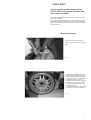
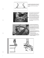
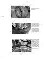
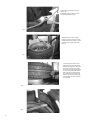
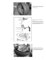
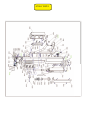
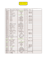
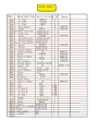
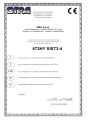
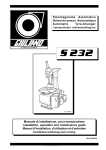
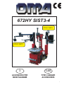
672HY SIST3-4
672HY SIST4
672HY SIST3
I
GB
ACCESSORIO PER
SMONTAGOMME
TYRE CHANGER
ACCESSORIES
1
2
Manuale di istruzioni per l’uso e la
manutenzione dello
ACCESSORIO PER SMONTAGOMME
Instructions and maintenance manual for
TYRE CHANGER ACCESSORIES
Model 672HY SIST3-4
Modello 672HY SIST3-4
Matricola N°
Serial N°
Anno di costruzione
Year of manufacture
COSTRUTTORE:
MANUFACTURER:
OMA S.p.A.
Sede centrale: Via dell'Artigianato, 64
36045 LONIGO (VI) - ITALY
Telefono ++39 0444 436199
Telefax ++39 0444 436208
OMA S.p.A.
Head office: Viadell'Artigianato, 64
36045 LONIGO (VI) - ITALY
Telefono ++39 0444 436199
Telefax ++39 0444 436208
1th Edition - 19/10/2007
1ª Emissione 19/10/2007
CENTRO DI ASSISTENZA
AUTORIZZATO:
AUTHORISED SERVICE CENTRE:
1
Indice
672HY SIST3
Contents
Pag. 3
Smontaggio del pneumatico
Pag. 3
Montaggio del pneumatico
Pag. 6
672HY SIST4
2
Page 7
672HY SIST3
Page 3
Demount the tyre
Page 3
Mounting the tyre
Page 6
672HY SIST4
Page 7
672HY SIST3
User’s manual for the helping device
672HY SIST3 used on the machine with
20.or larger turntable
The helper of ASSISTANT H3 can be used on the machine with
20.or larger turntable.
It can improve the working efficiency, make the operation safely
and easily, especially for the stiff, low profile tyre. Before use this
helper, user read the machine manual first,use the helper reference to this manual.
Demount the tyre:
1.Release all the air inside the tyre.
2.Remove the weight on the rim. (Fig.1)
(Fig.1)
Fig.1
3. Place the tyre between the bead
breaker blade and rubber pad, then
place the bead breaker blade between the bead and tyre. The bead breaker blade should 2 cm from the
bead,then step the pedal to separate
the bead from the tyre,(Fig.2) make
the valve keep a distance from the
bead breaker shoe.
4. Repeat the operation until the bead
is separate from the rim completely
Fig.2
3
5. Choose the locking style according to the
different rim, then lock the tyre on the turntable.(For the aluminum rim, we use outside locking, but not use inside locking)
(Fig.3)
Fig.3
Fig.4
6.when operate the low-profile and stiff
tyre, position the clamp within the demand dimension, put the rim on the
turntable, put the pressing roller
(Fig.4-1) on center hole of the rim, dial
down the valve(Fig.4-2), press down
the rim until rim position to the surface
of clamps, (Fig.3), press down the pedal, the rim will be locked. Dial up the
valve (Fig.4-2) to lift the pressing roller, to make it in the out working position, take out the pressing roller, put it
on the support.
7. Press the tyre by pressing blade(Fig.5-1) to make the rim separate
from the tyre. (Lubricate the tyre and
rim, by the brush with the commercial
lubricant(liquid state or cream state),
other lubricant can not be used. Choose the demount direction according to
the direction of the tyre.
Fig.5
Fig.6
4
8.Put the hexangular shaft in the working position, (Fig.5-3)make the mounting head near to the bead (Fig.5-2),the
distance from the rim to
mounting head should be
4-5mm(Fig.6), locking the pull-push
horizontal arm(full-automatic); or swing
arm (the semi-automatic machine positioned by handwheel)
Press the tyre by pressing blade near to
the mounting head,(Fig.7-1).Place the
lever (Fig.7-2)between the tyre and mounting head.
Fig.7
Fig.8
Uplift the pressing blade to the other
side of the mounting head, press the
tyre, lifter the bead to the mounting
head, (Fig .8), press the pedal, to rotate
the turntable in clockwise , until the
bead separate completely. In order not
to damage the valve on the tyre, it will
keep the distance from the mounting
head during the operation, the distance
should be 10mm on the right side.
Note: if the operation not smoothly, stop
at once, lift the pedal, rotate the turntable in the counter clockwise direction, to
get the obstacle out.
Fig.9
10.Take out the tube if there has, demount the other side of the tyre, place
the bead breaker disk under the lower
part of the tyre,(Fig.9) , insert the lever
to the tyre and lift the tyre on the mounting head (Fig.10), press the pedal
to rotate the turntable clockwise,
demount the tyre.
Fig.10
11.Take off the tyre from the rim,
get off the rust and oxidation material on rim and tyre.
5
Mounting the tyre:
Note:Make sure the tyre is match to the rim.
1. Lock the rim on the turntable.
2. Lubricate the tyry and rim on
both sides. (Fig.11)
Fig.11
Fig.12
3.Make the mounting head
on the edge of rim, the valve
face to the mounting head,
put the tyre on the upside of
tail of the mounting head,
and the other side under the
front part of the mounting
head, meantime press the
tyre to the seat of the rim
(Fig.12) Press the turntable
control pedal, the turntable
will rotate in clockwise direction, mount the bottom part
of the tyre on the rim.
4. Continue the operation,
to mount the tyre, if the
tyre is wide or low-profile
or stiff, we can press the
pressing blade,(Fig.12)rotate the turntable in clockwise about 90°, then fix
the pressing device to the
mounting head, (Fig.13)
then rotate the turntable
until the operation is finish.
(Fig.13)
For the others please reference to the manual.
Fig.13
6
672HY SIST4
Fig.1
User’s manual for the helping
device672HY SIST4
1. Connect the electrical and air supply to test
the machine,if there is no problem, then tilt back
the vertical arm.
2.Release all the air inside the tyre.
Remove the weight on the rim. (1)
Fig.2
3. Place the tyre between the bead breaker blade and rubber pad,then step the bead breaker
cylinder control pedal to separate the bead from
the rim, make it repeat until the bead is separate from the rim completely (include the other
side). (2)
4.If the rim is aluminum, which one can only
clamped from the outside, the cover should be
put on. Open the four jaws, place the tyre on
the turntable, then clamp the rim tightly. (3)
Fig.3
5.Press the tyre by the roller, grease the bead with the greaser. (4)
Fig.4
6.Tilt forward the vertical
arm, and lock the position
of the mounting head. (5)
Fig.5
7
7.Place the lever between the tyre
and rim. (6)
8.Uplift the roller and place it in the
non-working position. (6) (7)
Fig.6
9.Uplift the tyre to the mounting
head by the lever, then turn the turntable clockwise,to make the rim separate from the upper side of the
tyre. (7)
Fig.7
10.Insert the lever to the lower
seat of the tyre, place the bead
breaker disk under the lower part
of the tyre and uplift it, to make
the lower tyre to the upside of the
rim, then lower the bead breaker
disk to the non-working position
(8), press the lever to make the
lower tyre to the mounting head,
turn clockwise to make it separate completely.
Fig.8
Fig.9
8
11.Clean the oil dirt and dust on the rim,
and grease both sides of the tyre before
the mounting. (10)
Fig.10
12.Mounting the lower side of the tyre
first. (11)
13.Fix the upper side of the tyre and the
mounting head, place the pressing roller
on the tyre, on the other side of tyre pressed by the pressing blade, turn clockwise
to mount the upper side of the tyre.
Fig.11
14.Release the pressing roller and
bead breaker disk and set (12) them in
their non-working position, then release the tyre to finish the operation.
Fig.12
9
672HY SIST3
672HY SIST3
672HY SIST3
672HY SIST3
672HY SIST4
672HY SIST4
672HY SIST4
OMA S.p.A.
via dell'Artigianato - 36045 LONIGO (VI) - Italy
Telefono ++/+444/436199 - Telefax +/+444/436208
672HY SIST3-4
10/10/2007