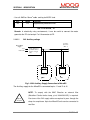
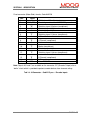
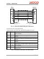
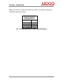
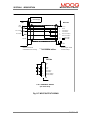
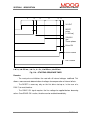
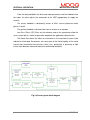
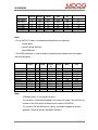
1
MicroDS “The motion solution” INSTALLATION and USER’S GUIDE Revision B – June 12 CONTENTS & INTRODUCTION Revision Date A B June 2003 June 2012 MicroDS User's Manual Description Updated Pages C27159-001 MicroDS Installation and User’s Guide C27159-001 Revision B, June 2012 Suggestions, corrections and comments should be sent to: Moog Italiana S.r.l. Electric Division Via Avosso 94 16015 Casella (Genova) Italy Moog Inc., East Aurora, New York 14052, USA. Moog GmbH, Hans Klemm Strae D-71034 Boblingen, Germany. PAGE I-1 MicroDS User’s Manual I1 I1 I2 I2.1 I2.2 I2.3 I2.4 I2.5 CONTENTS & INTRODUCTION TABLE OF CONTENTS and INTRODUCTION TABLE OF CONTENTS and INTRODUCTION INTRODUCTION USING THE MANUAL Safety Declaration of Conformity (EC) CE Requirements LEGAL ASPECTS 2 5 6 8 10 11 12 SECTION 1 DESCRIPTION 1.1 INTRODUCTION 1.2 PRODUCT RANGE 1.3 GENERAL FEATURES 1.4 TECHNICAL DATA 1.4.1 General features 1.4.2 Interfaces 1.4.3 Recovery Circuit 1.5 CODES 1.6 OPTIONS 1.7 DIMENSIONS AND DRILLING JIG 1.8 CONNECTION CABLES 1.9 EXTERNAL FUSES 1.10 POWER DISSIPATION 1.11 SOFT START 1.12 FANS 1.13 RESET BUTTON 1.14 POWER LINKS AND CONNECTORS 1.14.1 Power input voltage connectors 1.14.1.1 24V Auxiliary voltage 1.14.1.2 Motor power connector 1.14.1.3 Mains Voltage Supply 1.14.1.3.1 SINGLE PHASE OPERATION 1.14.1.4 PARALLEL DC BUS OPERATION 1.15 Recovery circuit 1.16 CONTROL CARD LINKS AND CONNECTORS 1.16.1 Encoder input connector 1.16.2 Resolver input connector 1.16.2.1 G400 and G330 motors resolver wiring 1.16.3 Input References Connector 1.16.4 Drive enable connector 1.16.5 Encoder Connector (output) 1.16.6 RS485 Serial link 1.17 Drive Starting Sequence. 1.18 Dynamic Braking 1.19 MECHANICAL BRAKING 1 1 1 2 4 4 5 7 8 10 11 12 13 13 14 14 14 15 16 17 18 19 19 20 20 23 24 28 32 34 36 38 39 40 42 43 PAGE I-2 CONTENTS & INTRODUCTION MicroDS User's Manual SECTION 2 INSTALLATION 2.1 INTRODUCTION 2.2 INSTALLATION REQUIREMENTS 2.3 ELECTROMAGNETIC COMPATIBILITY 2.3.1 EUROPEAN DIRECTIVE EMC (89/336/EEC) 2.3.2 FILTERING 2.3.2.1 Filter types 2.3.2.2 FILTERS MECHANICAL DIMENSIONS 2.3.2.3 Filter installation 2.3.3 Wiring and shielding 2.3.4 Recovery resistor 2.3.5 Shielding 2.3.6 Safety Aspects 2.4 Summary of Connection Instructions 2.4.1 Feedback connection (encoder or resolver) 2.4.2 “Temporary” / test power wiring 2.4.3 Summary of power wiring 1 1 1 3 3 4 4 5 6 8 11 11 12 13 13 13 14 SECTION 3 STARTUP 3.1 INTRODUCTION 3.2 DRIVE SETTING UP INFORMATION 3.3 First start-up (on test bench, for testing purposes) 3.4 Configuration for installation in the electrical cabinet. 1 1 1 3 3 SECTION 4 OPERATION 4.1 INTRODUCTION 4.2 GENERAL PRINCIPLES 4.2.1 Input electric power conversion 4.2.2 Output electric power conversion 4.2.3 Control section 4.2.4 High Speed operation 4.3 CONTROL LOOPS OPTIMIZATION 4.3.1 Current loop optimization 4.3.2 Speed loop optimization 1 1 1 1 2 2 4 4 4 5 SECTION 5 COMMANDS 5.1 DESCRIPTION 5.2 MOTOR PARAMETERS MENU 5.2.1 DESCRIPTION OF MOTOR PARAMETERS 5.2.1.1 Description of Resolver parameters 5.2.1.2 Description of Encoder Parameter 5.3 DRIVE PARAMETERS MENU 5.3.1 DESCRIPTION OF DRIVE PARAMETERS 5.4 CONTROL LOOPS PARAMETERS MENU 5.4.1 DESCRIPTION OF CONTROL LOOPS PARAMETERS 5.4.1.1 SPEED LOOP PARAMETERS 1 1 4 5 8 8 9 10 16 17 17 PAGE I-3 MicroDS User’s Manual CONTENTS & INTRODUCTION 5.4.1.2 CURRENT LOOP PARAMETERS 5.5 Enable menu 5.5.1 Description of Enable Menu 5.6 DISPLAY VARIABLES MENU 5.6.1 Description of Display Variables menu 5.7 UTILITY MENU 5.7.1 Description of Utility, Configuration Analog Out Sub Menu 5.7.2 Description of Utility, Parameter Sub menus 5.7.3 Description of UTILITY, Phasing & Save Program Sub Menu 5.7.4 Description of UTILITY, OFFSET sub MENU 5.8 Keyboard Lock Menu 5.8.1 Description of Keyboard Lock/Unlock Menu 5.9 FAULT MENU 5.9.1 Description of Fault Menu 18 19 19 20 21 23 24 26 27 29 30 30 31 31 SECTION 6 CONTROL LOOPS 6.1 INTRODUCTION 6.2 CURRENT LOOP 6.3 SPEED LOOP 6.4 ADDITIONAL CONTROL STRUCTURES 6.4.1 Soft-start Control 6.4.2 Recovery resistor control circuit 6.5 Additional Drive Data 6.5.1 Output current from the DC Bus connection 6.5.2 Max Recovery Current on MicroDS Drives 1 1 1 1 2 2 2 3 3 3 SECTION 7 TROUBLESHOOTING 7.1 INTRODUCTION 7.2 Faults on drive power supply circuit 7.3 Faults on output section 7.4 Faults on feedback section 7.5 Control loops trouble 1 1 2 3 4 5 Appendix A : Warranty Appendix B : Motors technical data Appendix C : Special Motors 1 2 4 PAGE I-4 CONTENTS & INTRODUCTION I2 MicroDS User's Manual INTRODUCTION Introductory note: This manual details the MicroDS. This drive is a product line extension of the present DS2000 “The Motion Solution” drive range. Thus, functionally, these drives are almost identical. Some differences exist in the dynamic braking/recovery resistor functionality and various other functions which are detailed in the following chapters. CAUTION: Repairs or modifications to the product by anyone other than a Moog authorized repair facility may create unsafe operating conditions and will invalidate the product warranty. PAGE I-5 MicroDS User’s Manual I2.1 CONTENTS & INTRODUCTION USING THE MANUAL This user’s manual is intended to provide sufficient information on how to install, wire and tune a Moog brushless electric motor system. This user’s guide must be read and understood before applying power and operating the equipment described. This equipment must be installed and serviced only by duly qualified service personnel. All information in this manual is directed towards such persons only. Individuals responsible for the installation of the equipment described in this user’s guide must ensure; 1) only technically qualified individuals are employed to work on the installation, 2) these qualified individuals must have the accompanying documentation available at all times when working on the installation and are obliged to use this documentation in a consistent manner, and 3) work on, or close to, the installation is prohibited for non-technically qualified individuals After installation and before starting up the motor it is also recommended to check all system parameters to ensure correct system configuration. Particular attention must be paid to all safety instructions. PAGE I-6 CONTENTS & INTRODUCTION MicroDS User's Manual NOTES: Moog assumes no responsibilities for errors or omissions due to the information in this manual. This manual is subject to changes at any time and Moog is not obliged to inform users of manual updates The information in this manual is subject to revision due to product modifications and/or improvements. The manual can differ from previous manual versions. PAGE I-7 MicroDS User’s Manual I2.2 CONTENTS & INTRODUCTION Safety The safety instructions provided in this Manual are included to prevent injury to personnel (WARNINGS) or damage to equipment (CAUTIONS). WARNINGS serve to make personnel aware of potentially hazardous actions that may result in personal injury or death. CAUTIONS are to alert personnel to actions that could cause equipment damage, resulting in the equipment becoming unsafe. Required for CE-Compliance CE-Compliance indicates where a particular application-related safety or EMC requirement is driven by the need for CE-Compliance of the MicroDS when installed in the system. Customers who do not need CE-Compliance on their machinery may choose not to implement these features. WARNING: DO NOT remove or replace any assemblies, subassemblies or components with primary power present. WARNING: Lethal voltages (≥790Vdc) remain present within this equipment when the mains power is removed. It is recommended to refrain from commencing any servicing, maintenance, repair or upgrading of this equipment until at least five minutes after power shutdown. It is further recommended to measure the voltage level at all high voltage terminals before commencing any such activities, to ensure that no lethal voltages are present. WARNING: The removable plug-in connectors of the MicroDS Drives are for ease of wiring installation. These removable plug-in connectors are not suitable for connection or disconnection under power. All connections must be made with power removed. WARNING: Repair or internal adjustments to the MicroDS Series Controllers must not be attempted. All faulty items must be returned to Moog Service Centres for maintenance and repair. WARNING: High Voltage. The recovery resistor is connected to the Drive DC Bus and can have voltage ≥790Vdc. PAGE I-8 CONTENTS & INTRODUCTION MicroDS User's Manual WARNING: Do not touch recovery resistor during operation to avoid burns. CAUTION: Ensure that the correct input voltage, 230V or 400V, has been set. CAUTION: If an emergency stop is required, opening U-V-W pins and closing motor phases to resistors, must be preceded by disabling the axis. The delay time must be at least 30 ms. CAUTION: In case of repeated on/off switching, wait 1 minute between power removal and subsequent reapplication. CAUTION: Cooling air to the MicroDS must be kept clean. The air supply must not contain particles that may deposit causing obstruction to airflow. It is recommend to periodically check the airflow. CAUTION: Do not exceed the tightening torque values given in the following table. See Section 2 of this Manual for the recommended tightening torque of the terminal blocks Screw Thread M3 M4 M5 M6 M8 Tightening torque [Nm] [lb in] 1.00 8.85 3.00 26.55 6.00 53.10 8.00 70.80 20.0 177.0 PAGE I-9 MicroDS User’s Manual I2.3 Declaration of Conformity (EC) PAGE I-10 CONTENTS & INTRODUCTION CONTENTS & INTRODUCTION I2.4 MicroDS User's Manual CE Requirements Required for CE-Compliance • Protection against electric shock. Electronic Equipment intended for installation in closed electrical operating areas should be kept locked. Authorized person shall only open the lock and access should only allowed to skilled persons while the drive is energized. Where the equipment requires manual intervention, 412.2.1 of HD 384.4.41 S2 shall be consulted. • Fixed connection for protection. The equipment may have a continuous leakage current of more than A.C. 3.5 mA or D.C. 10 mA in normal use. The MicroDS must be permanently and reliably connected to Earth and all conductive parts in the IP54 rated enclosure or cabinet must be permanently connected to Earth. The impedance between the earth terminal and any accessible part of the enclosure or cabinet should be less than or equal to 0.1 . • External DC Supply Voltage Sources. All external d.c. supply voltages used with the T200 Series Controllers must be derived from a Safety Extra Low Voltage (SELV) supply as defined by standard EN60950. Such SELV voltages do not exceed a value of 60 Vd.c. or 42.4 Va.c. peak under normal conditions and are supplied by circuits which are separated from all hazardous voltage conductors by permitted safety methods such as reinforced insulation. • RCD. A D.C component can occur in the fault current in the event of a fault connection to earth. Only a residual-current-operated protective device (RCD) of Type B is allowed. When the protection in installations with regard to indirect contact is achieved by means of an RCD, their appropriate function/combination shall be verified. • Climatic Conditions. Equipment intended to operate within its performance specification over the range of Class 3K3, as defined in table 1 of EN 60721-3-1, EN 60721-3-2, EN 60721-3-3, EN 60721-3-4, partly modified. • Installation - The MicroDS must be mounted in a vertical orientation. The MicroDS must be panel mounted within an enclosure or cabinet which provides a degree of ingress protection against liquids and objects of at least IP54. Such enclosures or cabinets must be accessible to technically qualified service or maintenance persons only. • EMC Requirements. The installer of the equipment is responsible for ensuring compliance with the EMC standards that apply where the equipment is to be used. Product conformity is subjected to filters installation and to recommend procedures, detailed in this Manual. • Second Environment (EMC).This equipment intended to be connected to an industrial low-voltage power supply network, or public network, which does not supply buildings used for domestic purposes (second environment, according to EMC PAGE I-11 MicroDS User’s Manual CONTENTS & INTRODUCTION Standards). If connected to a low-voltage public network that supplies domestic premises (first environment), this product may cause radio interference in which case supplementary measures may be required. • Cable Shielding. Shielding of some external cables is necessary to ensure compliance with EMC requirements. Details of these requirements are given in Section 1 and Section 2. • The Integral Motor Thermal Protection signal shall be connected on the equipment, on T360 connectors J4/J5 (PIN 2-15/6-8), which accepts signals maximum 5.5 Vdc ±10%, 400 µA. The ultimate result of this signal is to "SwitchOFF" the output of the Solid State Motor Controller and thereby "No-Power" is transmitted to the Motor connected to the Motor-Drive. I2.5 LEGAL ASPECTS This manual can only be used by final Customers/Users of the Moog product it describes. This manual cannot be reproduced in whole or in part without prior written consent from Moog. No distribution of this manual by electronic, mechanical, or printed means is allowed. This manual has been issued with the intention of providing all information necessary to perform a complete installation of the MicroDS. Moog assumes no responsibility for errors or omissions contained herein and for incidental or consequential damages due to the above mentioned errors and omissions. Moog reserves the right to change and update this manual without notice. This manual is for information purposes only. Moog assumes no responsibility with regard to the correspondence of the product features described in the manual and the features on the actual product purchased by the final Customer/User. No statement or sentence contained in this manual implies further legal obligations, different from those contained in each sale or supply contract regarding Moog products. PAGE I-12 SECTION 1 : DESCRIPTION SECTION 1 1.1 MicroDS User's Manual DESCRIPTION INTRODUCTION This manual describes the MicroDS drive series and provides information about the installation and the functional characteristics of the product. This section describes MicroDS drive features and also refers to the ordering system. 1.2 PRODUCT RANGE MicroDS is a digital drive for permanent magnet synchronous servomotors (hereafter: brushless). Vector control of asynchronous servomotors (hereinafter: asynchronous) is also possible. The range is made up of 2 models, corresponding to 3 Arms and 6 Arms nominal currents. The transducers available with the motor are either an incremental encoder or a resolver. An internal recovery resistor is provided in the drive. An optional second external recovery resistor is also available. The Moog GUI software pack is available to manage, by means of a PC, both the drive configuration and the display of all internal values. The manual together with the notes in the Appendices provides a complete description of the drive. PAGE 1-1 MicroDS User’s Manual 1.3 SECTION 1: DESCRIPTION GENERAL FEATURES The MicroDS features provide the automation industry with the best response to the most difficult requirements of motion control. FULL DIGITAL: - Speed and current control loops and many other functions such as the DC BUS status monitoring, soft-start and recovery circuit management and protection are implemented digitally to ensure reliable and flexible operation. - The digital operation ensures maximum system stability and reliability over time, temperature and varying application conditions. - Settings are carried out through values calculated in analytic models and do not depend upon potentiometric calibrations. FLEXIBLE: - Any brushless motor can be controlled by entering a maximum of 8 parameters which adjust the current loop and identify the motor electromechanical characteristics (peak current, Back EMF, inductance, resistance, number of poles, voltage rating, speed, feedback encoder pulses characteristics, resolver poles). - The drive can control asynchronous motors by means of vector control. By entering the additional parameters, magnetization current (ID) and the slip gain (frequency), it is possible to use asynchronous motors. The remaining parameters related to the hardware features remain active. - The motor position transducer can be either a resolver (with 2 to 24 poles) or an incremental encoder (from 1024 to 8192 pulses). For the resolver, internal hardware gain adjustment allows maximum resolution be achieved depending on the transform ratio of the resolver. The required gain setting should be specified (for FAS or Global motor) in the drive order code. - It is possible to program the device in 2 different languages: Italian and English; the required language should be specified in the order code. At any time, using the GUI, it is possible to load a different language. Only one language can be active in the drive. PAGE 1-2 SECTION 1 : DESCRIPTION MicroDS User's Manual - The input supply voltage can range from 65 VAC to 510 VAC three-phase. Operation with a single-phase power supply is also possible with appropriate de-rating. - Unlike the DS2000 models, it is necessary to supply 24V backup power at all times. ADVANCED PERFORMANCE: The current loop, based on a traditional PI structure, is provided with automatic compensation algorithms for the Back EMF and of the KP/KI ratio, as a function of the motor characteristics. Hardware calibration is not necessary for the current loop. Current loop update rate: 10kHz. Speed Loop Update rate: 5kHz. PAGE 1-3 MicroDS User’s Manual 1.4 SECTION 1: DESCRIPTION TECHNICAL DATA 1.4.1 General features Three-phase input voltage rating: from 230Vac to 460Vac ±10%, 50/60 Hz Single-phase Input voltage rating: 230Vac (Input Power limited to 1.1kW) Min/max Three-phase input voltage: 65 / 510 Vac (DC-Bus: 80 / 720 Vdc) Auxiliary voltage (required): 24 Vdc ±10% , 1A (SELV) Configurable analog references: from 3.2 to 10 Vdc Recovery Resistor: 120, 100W (6 Arms Drive) 120, 50W (3 Arms Drive) Max dynamic with encoder 200 Hz Switching frequency: 10 kHz Speed adjustment: 0 ÷ 9999 rpm Anti-resonance low-pass filter: 20 ÷ 800 Hz Filter on reference: 1 ÷ 800 Hz Notch filter (programmable): 50 ÷ 1500 Hz Ambient temperature: 0 ÷+40 °C (exceeding Class 3K3) Storage temperature: -25 ÷ +55 °C (Class 1K4) Transport temperature: -25 ÷ +70 °C (Class 2K3) Relative humidity: 5% to 85% (with no condensation and no formation of ice) Environment: For use in a pollution degree 2 environment. Derating for altitude >1000 m: 1% every 100 m Air Pressure 86 kPa to 106 kPa PAGE 1-4 SECTION 1 : DESCRIPTION MicroDS User's Manual 1.4.2 Interfaces - Analog - Speed (or current) reference differential input: 0 +/- 10V (adjustable scale) - Auxiliary input voltage: 24Vdc ±10%, 1A - Output Voltage: 15±10% Vdc, 100mA - Analog output (configurable) - Tachometric signal (adjustable scale) - Peak current limit (via analog signal) - Motor temperature (through PTC or NTC) - Resolver interface - Digital - RS485 full-duplex serial link - encoder input (incremental) - encoder output (incremental) - reset - drive OK output - drive enable input - reference enable input PAGE 1-5 MicroDS User’s Manual SECTION 1: DESCRIPTION Drive front control panel Fig 1.1 MicroDS Front Panel PAGE 1-6 SECTION 1 : DESCRIPTION MicroDS User's Manual Protection - motor overtemperature - drive overtemperature - IGBT module current foldback - input voltage out of tolerance - bus overvoltage - internal recovery resistor power limiting - encoder or resolver signal missing - encoder or resolver faulty connections - axis short circuit (motor and recovery resistance output) - Overspeed in torque mode control (if speed is 12% above max set value). 1.4.3 Recovery Circuit Dynamic braking unit MicroDS Model code T360xx03x-xxx xxx T360xx06x-xxx xxx Standard recovery resistance (Internal) Currents (rms/pk) Resistance and power 3/11 6/22 120Ω/50W (int.) Max Current Max Duty Cycle1 6.25 1.05% 6.25 2.1% 2 120Ω/100W (int.) 3 Tab 1.1 Recovery resistance data 1 Operating with 600V DC Bus. An equivalent resistor of equal resistance and power rating (Order code: C25722-003-121) can be attached externally to the drive if required. For operation at 230V, a lower value resistance can be connected externally. Consult Moog sales office for futher details. 2 PAGE 1-7 MicroDS User’s Manual 1.5 SECTION 1: DESCRIPTION CODES The MicroDS can be ordered using the boxcar shown in Fig 1.2. PAGE 1-8 SECTION 1 : DESCRIPTION MicroDS User's Manual Numeric Numeric/Alpha Alpha Numeric Numeric Alpha Alpha/Numeric T360 X X XX X - XXX XXX Model Series Designator Current Model Design Status Resolver Gain Option Base Model Size Letter E (E model) No. Drive Size 03 3/11 06 6/22 No. Option Description 0 Resolver Transform Ratio = 0.25 (FAS Motors) 1 Resolver Transform Ratio = 0.5 (Global/FASG Motors) Current Hardware Revision A Software Revision Rev. Description 31E MicroDS NTC/PTC & IT Limiting, English Menus 31I MicroDS NTC/PTC & IT Limiting, Italian Menus Reserved Number Description 000 Default drive settings Accessories: Graphical User Interface (GUI) part number is CZ5300 RS232/422/485 Converter part number is CZ5200 Users manual is available @ www.moog.com Note: 1) Users must be experienced/qualified in the use of this product range before building products from this drawing. 2) All drive options are provided with a 120Ohm Internal Regen Resistor 3) External regen resistors are to be ordered and supplied seperately. Fig 1.2 MicroDS Drive BoxCar PAGE 1-9 MicroDS User’s Manual 1.6 SECTION 1: DESCRIPTION OPTIONS Optional devices separately supplied are - RS232/422/485 Converter (Moog code CZ5200) - Moog GUI communication program (Moog code CZ5300) PAGE 1-10 SECTION 1 : DESCRIPTION 1.7 MicroDS User's Manual DIMENSIONS AND DRILLING JIG The following figures show the drives dimensions and details and drilling information for mounting the drive. Fig 1.3 A Size drive dimensions and drilling jig (in mm.) PAGE 1-11 MicroDS User’s Manual 1.8 SECTION 1: DESCRIPTION CONNECTION CABLES The following table shows the cables specification for each part of the drive. Use Class 1 wire only It is recommended to use copper (Cu) cables, 60/75°C, UL certified, with the cross sections indicated in the table. Line power cable (no. of conductors x AWG) Protective bonding cable (no. of conductors x. AWG) Motor power cable (no. of conductors x. AWG) Recovery resistor cable (no. of conductors x. AWG) 24V power cable (no. of conductors x AWG) Motor encoder cable (no. of conductors x. AWG) MicroDS Model A Size 3/11 6/22 3 x 14 AWG 3 x 14 AWG Notes EMC Filter required. See Section 2 for details. 1 x 6 AWG 1 x 6 AWG 4 x 14 AWG 4 x 14 AWG shielded 2 x 14 AWG 2 x 14 AWG shielded 2 x 14 AWG 16 x 22/20 AWG 4 Turns on Fairrite core. Schaffner p/n # 00443164151 shielded shielded Motor resolver cable (no. of conductors x AWG) 8 x 22/20 AWG Tab 1.2 Dimensions of connection cables Note: The DC Bus connection between drives has the same wire size as the Recovery resistor. It must also be shielded. AWG 22 20 18 16 14 12 10 8 6 4 mm2 0.3 0.5 0.8 1.3 2.1 3.3 5.3 8.4 13 21 Tab 1.3 Conversion from AWG to mm2 PAGE 1-12 SECTION 1 : DESCRIPTION 1.9 MicroDS User's Manual EXTERNAL FUSES CAUTION : Equipment suitable for use on a supply capable of delivering not more than 5000RMS Symmetrical Amperes ,460V +10% maximum. No fuses are provided inside the drive. It is recommended to use UL certified fuses and fuse blocks as manufactured by BUSSMAN Div. Cooper LTD (UK). MicroDS Model A size 3/11 Short Circuit Rating Notes 6/22 5000 rms Amps 32A, 550 Volt, Type HRC Power line fuse Recovery Resistor 3 fuse 1000VDC, 3A 24 Vdc auxiliary power supply fuse Semiconductor Ferraz Shawmut , A120X range. Delayed 3A 250V Tab 1.4 Recommended fuses 1.10 POWER DISSIPATION To determine the thermal requirements of the cabinet, in which the drive is to be installed, it is necessary to refer to Tab 1.5. The power dissipation referred to in the table assumes the drive is operating at continuous rated current. If the application employs continuous braking, it is necessary to add the recovery resistor power dissipation (use the nominal recovery power if that required by the application is unknown). MicroDS Model Power 3/11 6/22 53W 98.8W Tab 1.5 Power dissipation 3 The fuse specified is for operation with a nominal DC bus of 600V. For operation at lower DC bus voltages (300V), a lower voltage and current fuse can be specified. PAGE 1-13 MicroDS User’s Manual SECTION 1: DESCRIPTION 1.11 SOFT START The soft start circuit (current limit at start-up) is included in the drive-input stage. 1.12 FANS The MicroDS ventilation is provided by one fan mounted over the drive. Fan power is generated internally. CAUTION: Free air circulation must be ensured for correct fan operation. 1.13 RESET BUTTON A reset button is available on the drive front panel. It allows the digital control card to be reset. It can also be used during start-up to access the download data mode. PAGE 1-14 SECTION 1 : DESCRIPTION MicroDS User's Manual 1.14 POWER LINKS AND CONNECTORS Remark: Moog MicroDS drives include all necessary connectors for correct operation. All the drives are equipped with plug-in connectors to ensure quick and easy connection of the drive in the control cabinet. These connectors also facilitate service and repair activities. The MicroDS connectors allow for easy mounting of the drive inside the control cabinet, providing the customers with the option of separating the cabinet assembly from system completion with servo-systems. The following sections detail the connectors and their specifications for each function of the drive and their associated accessories. PAGE 1-15 MicroDS User’s Manual SECTION 1: DESCRIPTION 1.14.1 Power input voltage connectors A SIZE: Power supply, recovery resistance, motor output connections and 24V supply are grouped together on connector J6, on the drive’s lower side. The conductors are fastened by means of screw terminals. - Fixed connector: 12 pins, male connector - Mating connector, 12 pins, female, supplied with the drive - A size wiring: cable 14AWG (2.1 mm2). Wire stripping: 7 mm. - Tightening torque: 0.5Nm. Pos. 1 2 Name DCDC+ 3 4 RR L1 5 L2 6 L3 7 8 9 10 11 12 PE W V U +24V GND (24V) Function DC Bus Voltage minus connection External recovery resistance and DC Plus of DC Bus plus connection External recovery resistance Phase "L1", three-phase voltage input 230/460Vac ±10% Phase "L2", ", three-phase voltage input 230/460Vac ±10% Phase "L3", ", three-phase voltage input 230/460Vac ±10% Protective Earth Phase "W", motor three-phase output Phase "V", motor three-phase output Phase "U", motor three-phase output Auxiliary voltage inputs 24 Vdc ±10%, 1A Auxiliary voltage inputs return Tab 1.6 J6 Power connector, A Size Remark: Pins 11 and 12 are the 24-Volt auxiliary voltage inputs. Pin 12 is connected to drive logic 0 and PE. PAGE 1-16 SECTION 1 : DESCRIPTION MicroDS User's Manual - Use a 6 AWG or 10 mm2 cable and lug for M5 PE stud. Pos. PE Name PE Function Equipotential protection circuit. Tab 1.7 PE Screw, A Remark: In electrically noisy environments, it can be useful to connect the motor ground to the PE stud and pin 7 of J6 connector to PE. 1.14.1.1 24V Auxiliary voltage To further µDS Units (Max. 4) 24V Auxiliary Supply +24V GND (24V) Fairrite Clamp Core p/n # 00443164151 (4-Turns of Supply cable) 11 12 11 12 Connector J6 Connector J6 µDS µDS Fig 1.4 24V Auxiliary Supply Connection to MicroDS The Auxiliary supply for the MicroDS is connected to pins 11 and 12 of J6. NOTE: To comply with the EMC Directive an external filter (Schaffner Fairrite ferrite clamp, p/n # 00443164151) is required. Required for CE-Compliance Four turns of the 24V supply cable are required to pass through the clamp for compliance. Upto four MicroDS units can be connected to one filter. PAGE 1-17 MicroDS User’s Manual 1.14.1.2 SECTION 1: DESCRIPTION Motor power connector The motor phase connections are made on J6 as detailed in Tab 1.6. The motor phase cable must be shielded to comply with the EMC Directive. The connections are shown in Fig 1.5. See also Section 2 Installation. µDSµ D S Motor U U (10) V V (9) W W (8) PE PE J6 J9/J10/J11 grounding of shield via connector clamp (or RF connection to ground screw in case of terminal board) grounding of shield via connector clamp Fig 1.5 Motor phases wiring CAUTION: U-V-W sequence at the drive side must match the corresponding U-V-W sequence at the motor side. NOTE: To comply with the EMC Directive the motor cable Required for CE-Compliance PAGE 1-18 must be shielded and the shield must be connected to the housing with a 360° connection at both ends. SECTION 1 : DESCRIPTION 1.14.1.3 MicroDS User's Manual Mains Voltage Supply The mains supply voltage is connected to pins 4, 5 and 6 of J6. These lines do not require shielding. For EMC compliance, they must be connected to the input EMC filter. The input PE connection should be tied to the PE stud detailed in Tab 1.7. NOTE: To comply with the EMC Directive, an input EMC filter Required for CE-Compliance is always required. Details of the recommended filters are given in Section 2, Installation. a.c. Mains L1 L2 L3 Protective Earth EMC Filter, Fuses etc. See Section 2 Installation To further µDS. (Max. 4) 4 5 L1 L2 6 L3 PE Stud Connector J6 µDS 4 L1 5 L2 6 L3 PE Stud Connector J6 µDS Fig 1.6 AC Mains Wiring 1.14.1.3.1 SINGLE PHASE OPERATION The MicroDS can operate from a single phase 230V supply. This will result in a DC bus of 320V. However, it is necessary to power limit the application to an input power of 1.1kW. Increasing the power beyond this point will result in the drive reporting an undervoltage due to excessive voltage ripple on the DC bus. To avoid this, the MicroDS should, where possible, always be connected to a three phase supply. If the MicroDS is connected to a single phase supply, an EMC filter must be installed. This is detailed in Section 2. PAGE 1-19 MicroDS User’s Manual 1.14.1.4 SECTION 1: DESCRIPTION PARALLEL DC BUS OPERATION The DC bus is available on pins 1 and 2 of J6. Up to four MicroDS units can operate with their DC bus connections shared. This feature allows the MicroDS units to share recovered motor power. It also increases the effective recovery energy that the drives can dissipate, as all recovery resistors will operate in parallel. Care should be taken when paralleling the MicroDS units to ensure that the DC bus cables are kept as short as possible. See Section 2, Installation. The ratings of the DC link current is detailed in Section 6. NOTE: To comply with the EMC Directive the DC Bus cable Required for CE-Compliance must be shielded and the shield must be connected to the housing with a 360° connection at both ends. To further paralleled µDS. Max. 4 1 Tie Screen to chassis via EMC bracket. See Section 2 Installation 2 DC- DC+ Connector J6 µDS 1 2 DC- DC+ Connector J6 µDS Fig 1.7 DC Bus sharing Wiring 1.15 Recovery circuit Under braking conditions, the motor will return energy that cannot be sent to the line, as the rectifier circuit, formed by a diode bridge, is unidirectional. The regenerated energy will increase the DC-BUS voltage. When DC bus voltage reaches the intervention threshold, the digital control turns on the recovery power switch, thus connecting the recovery resistance across the DC bus and dissipating the motor braking energy as heat. PAGE 1-20 SECTION 1 : DESCRIPTION MicroDS User's Manual The correct sizing of the recovery resistance allows motor deceleration within the required times and protects the electrolytic capacitors and drive from overvoltage. The MicroDS is equipped with an internal recovery resistor. This resistor is protected in software to prevent the power dissipated exceeding the device ratings (Size:3 50W, 6.25A, Size 6 100W, 6.25A). The regeneration terminals are also available on J6, pins 2 and 3. An equivalent resistor can be connected externally to double the recovery power handling capability of the unit. The software model controlling the recovery resistor operation allows increased dynamic braking capability at the start of a dynamic braking cycle. This is achieved by modeling the thermal response of the recovery resistor. This allows the recovery circuit to turn on initially for a longer period of time thereby increasing the time for which peak power can be dissipated. The software limits the overall power dissipated to the ratings of the resistor. Recovery Resistor 2 3 DC+ RR Tie Screen to chassis via EMC bracket. See Section 2 Installation Tie screen to panel on which resistor is mounted. Connector J6 µDS Fig 1.8 Recovery Resistor Wiring If the recommended Moog external recovery resistor is used (C25722-003-121), it must be provided with suitable heatsinking. To achieve the rated power of the resistor, a heatsink of 400m x 400mm x 3mm is required. WARNING: High Voltage. The recovery resistance is connected to the DC-BUS which can reach a voltage of 790V. PAGE 1-21 MicroDS User’s Manual SECTION 1: DESCRIPTION WARNING: Do not touch recovery resistors during operation to avoid burns due to the heat it dissipates. CAUTION: In applications where the working cycle involves decelerations with high inertial loads, from high velocity in very short deceleration time, it is necessary to properly size the recovery resistance. In these cases, please contact Moog Service Centers. NOTE: To comply with the EMC Directive the recovery Required for CE-Compliance PAGE 1-22 resistance cable must be shielded and the shield must be connected to the housing with a 360° connection at both ends. SECTION 1 : DESCRIPTION MicroDS User's Manual 1.16 CONTROL CARD LINKS AND CONNECTORS The following connectors are common to all drives sizes and are all located on the drive front control card: • Encoder Input Connector, • Resolver Connector, • Reference Connector, • Drive Enable Connector, • Encoder Output Connector • RS485 Connector. These are detailed in the following sections. Sufficient depth must be allowed in the cabinet for the resolver and RS485 connectors and their associated cable bend radii. The recommended depth for these is shown in Fig 1.9. Fig 1.9 Resolver \ RS485 Bend Radius Requirements PAGE 1-23 MicroDS User’s Manual SECTION 1: DESCRIPTION 1.16.1 Encoder input connector Remark: Two sections form the motor control encoder. - The first, (UVW signals), generates signals used by the drive to power the motor phases. The number of motor poles defines this section. - The second, (ABC signals), generates reference signals, which are also available for motion control to an external CNC. The number of pulses in this section is defined according to the customer needs as well as the application requirements. - The connector for these signals is on the control card bottom side. - The floating encoder connector at the drive side is a Sub-D 15 pos. and is provided with the drive (Sub-D 15 pos. Code AK5221, conductive shell, Code AK4218). - All the motor encoder channels and the PTC/NTC for the motor temperature control must be connected to J4 connector located on the bottom side of the drive. - Incremental encoder signals are available as outputs on J2C connector. - For the encoder signals, It is recommended to use a low capacitance, shielded (with 85% min. coverage), multipolar cable with 22 AWG (0,30 mm2 ) or 20 AWG (0,50 mm2 ) conductors. - Cable length should not exceed 40 m. - It is recommended that the encoder and the motor power cable be separated, through the use of independent duct, by a distance of 30 cm (1’). - It is not recommended to make intermediate connections on the encoder cable. - Motor Encoder port for the Motor Encoder Channels and for the Motor Integral NTC/PTC Temperature Control (PIN 8-15). This Auxiliary-connector is referred to Limited Voltage / Current circuits (rated max 5.5 Vdc ±10%, 400 µA). PAGE 1-24 SECTION 1 : DESCRIPTION MicroDS User's Manual Fixed connector (Motor Side): female, Code AK4220 Pos. 1 2 3 4 5 6 7 8 9 10 11 12 13 14 15 name +5V GND (PTC) __ W W V __ V A __ A C __ C U __ U __ B B PTC +5 Vdc (max 100 mA) output Encoder ground and motor PTC/NTC ground Switching signal: W phase (compliment) Switching signal: W phase Switching signal: V phase Switching signal: V phase (compliment) A Channel A Channel (compliment) Marker Marker (compliment) Switching signal: U phase Switching signal: U phase (compliment) B Channel (compliment) B Channel Motor PTC/NTC Note: Signals A,B and C are available on the connector J2C (Encoder Output) after a “buffer” circuit which is provided to protect encoder devices from incorrect wiring. Tab 1.8 J4 Connector – Sub-D 15 pos. – Encoder inputs PAGE 1-25 MicroDS User’s Manual SECTION 1: DESCRIPTION Motor Motor µ DS A B V R G H 2 15 7 8 GND(PTC/NTC) GND(PTC) PTC PTC A Chann Channel e A Canale ChannelA(compliment) negato P N 14 13 CanaLe B B Channel Canale B negato B Channel (compliment) J K 9 10 Marker Marker Marker negato Marker (compliment) 11 12 Fase U U Phase Fase U negata U Phase (compliment) 5 6 Fase V V Phase Fase V(compliment) negata V Phase 4 3 Fase W W Fase PhaseW negata W Phase (compliment) 1 L M E F D C +5V J4 Shield connected to the housing by connector clamp Shield connected to the housing by connector shell Fig 1.10 – ENCODER CONNECTIONS PAGE 1-26 SECTION 1 : DESCRIPTION MicroDS User's Manual (FAE) Fig 1.11 Encoder connection at motor side for FAEN PAGE 1-27 MicroDS User’s Manual SECTION 1: DESCRIPTION 1.16.2 Resolver input connector The connector for these signals is J5. J5 is a female Sub-D 9 pos. and is located on the control card. - The resolver floating connector is a male Sub-D 9 pos. and is provided with the drive. - Depending on the resolver transform ratio, (0.5 for Global/FASG motors, 0.25 for FAS motors), a gain setting for the resolver circuit must be set internally during manufacture. The ordering information for this is included in the BoxCar. - The resolver signals should be connected to J5 connector. Fig 1.12 shows the resolver wiring lay-out with differential inputs. - It is recommended to use low capacitance, multipolar shielded cable (85% min. coverage) with 22 AWG (0,30 mm2 ) or 20 AWG (0,50 mm2 ) conductors (Order code: Bare cable B47885-001). - Cable length should not exceed 30 m. It is recommended that the resolver cable and the motor power cable be separated through the use of independent ducts and by a distance of 30 cm (1’). It is not recommended to make intermediate connections on the resolver cable. - With the resolver interface it is possible to provide simulated encoder outputs on J2C. The maximum number of pulses per mechanical revolution of the simulated encoder is 1024 ∗ resolver poles /2 (i.e.: for a 6 pole resolver, the number of pulses/revs is 3072) and the standard width of the marker is 90° (width of 180° or 360° is programmable via keypad). A lower number of pulses per revolution is programmable via keypad or through the Moog GUI. - Ready made cables for FAS and G400/G330 motors are available on request. Contact Moog sales for further information. - Motor Resolver port for the Motor Resolver Signals and for the Motor Integral NTC/PTC Temperature Control (PIN 6-8). This Auxiliary-connector is referred to Limited Voltage / Current circuits (rated max 5.5 Vdc ±10%, 400 µA). PAGE 1-28 SECTION 1 : DESCRIPTION MicroDS User's Manual Motor Connector J5 Connector (9-Way Sub D) cos ϕ cos ϕ C sin ϕ G 4 sin ϕ H 5 0V sin ϕ sin ϕ N 6 PTC A 8 PTC -Vref (0V) B 7 +Vref D 9 -Vref +Vref PTC PTC 1 E S Internal Shields (if Available) 2 3 cos ϕ cos ϕ Internal Shields (if Available) Shield connected to housing through connector clamp Shield connected to housing through connector shell Fig 1.12 - RESOLVER CONNECTIONS (FAST/FASK motors) Fixed connector: 9 pin, female, code AK4220 Floating connector: male, Sub-D 9 pos., code AK5220, provided with the drive. Pos. 1 Name Cos 2 Cos 3 4 Shield Sin 5 Sin 6 7 PTC ____ V ref 8 9 PTC V ref Differential cos signal non-inverted input amplifier from resolver windings. Differential cos signal inverted input amplifier from resolver windings. Shield (internally connected to 0V) Differential sin signal non-inverted input amplifier from resolver windings. Differential sin signal inverted input amplifier from resolver windings. Motor PTC/NTC input 10 kHz, 20Vpk-pk sinusoidal “negative” output signal to primary resolver winding. Motor PTC/NTC input 10 kHz, 20Vpk-pk sinusoidal output signal to primary resolver winding (carrier). Tab 1.9 - J5 Connector- Sub-D 9 pos.- FAST/FASK Resolver PAGE 1-29 MicroDS User’s Manual SECTION 1: DESCRIPTION MOTOR RESOLVER CONNECTOR (FAST and FASK) Signal FAS T/ FAS N/ type FAS K FAEN Pos. Pos. C 1 Cosϕ E 2 Cos ϕ V-Ref D 10 0V B 7 PTC N 8 PTC A 9 G 11 Sinϕ H 12 Sin ϕ shield S 3 Tab 1.10 Resolver connections to motor Fig 1.13 Resolver connection at motor side for FAST and FASK READY MADE MOTOR RESOLVER CABLES (FAST and FASK) Cable Part No: Length (m) L081-136-A001 L081-136-A002 L081-136-A003 L081-136-A004 L081-136-A005 3 5 10 15 20 Tab 1.11 Ready Made Resolver Cables (FAST & FASK) PAGE 1-30 SECTION 1 : DESCRIPTION MicroDS User's Manual Fig 1.14 Resolver connection at motor side for FASN and FASY PAGE 1-31 MicroDS User’s Manual 1.16.2.1 SECTION 1: DESCRIPTION G400 and G330 motors resolver wiring Global Motor Connector J5 Connector (9-Way Sub D) 1 1 2 Internal Shields (if Available) 4 2 3 0V 4 5 3 5 6 6 8 7 7 8 9 Shield connected to housing through connector clamp Shield connected to housing through connector shell Fig 1.15 - RESOLVER CONNECTIONS (G400\G330 motors) Terminal Motor side 1 N° Terminal Drive 1 2 2 3 4 4 3 5 5 6 6 8 7 7 8 9 Tab 1.12 Cross references between color and cables for G400/G330 - Terminals are identified on the motor side. - As G400 and G330 have an NTC for thermal feedback, it is necessary to set this in the motor menu of the MicroDS setup. - If the drive is to be used with a global motor, the order code must be specified for a resolver transform ratio of 0.5. PAGE 1-32 SECTION 1 : DESCRIPTION MicroDS User's Manual Note: As the resolver is locked mechanically in the motor, the customer must perform a PHASING using the drive utilities. READY MADE MOTOR RESOLVER CABLES (G400\G330 Motors) Cable Part No: Length (m) L081-138-A002 5 L081-138-A003 10 L081-138-A004 15 L081-138-A005 20 Tab 1.13 Ready Made Resolver Cables (G400\G330 Motors) PAGE 1-33 MicroDS User’s Manual SECTION 1: DESCRIPTION 1.16.3 Input References Connector The analog references (speed and current limit references) are available on J2A male connector, and accessible through a floating 4 pin female connector. The conductors are fastened using spring clips within the connector. These clips are released by depressing the tab with a screwdriver. - Fixed connector:- 4 pins male, MicroCombicon. - Floating connector:-insertion type, 4 pin, code AK4714 (provided with drive). Pos. Name 1 V Ref 2 _____ V Ref I limit 3 4 _____ I limit Description Differential, non-inverted input of speed or torque reference signal (0 - ±10V, corresponding to 0 -± Max input reference). The scale is adjustable via software from ± 3.2 to ± 10V in steps of 0.1 V. Input impedance is 10k. Differential, inverted input of speed or torque reference signal Differential, non-inverted input of analog current limit (0 - ± 10V, corresponding to 0 - 100% max set current). The scale is adjustable via software from ± 3.2 to ± 10V in steps of 0.1 V. Input impedance is 10k. Differential, inverted input of analog current limit Tab 1.14 Speed and Torque References connection PAGE 1-34 SECTION 1 : DESCRIPTION MicroDS User's Manual Example for speed and torque reference wiring µ DS S CNC 1 0 V Shield must o c obe ll e gRF a t o a l t e l a io s c h e rm connected housing c o n c o n n eto s sthe io n e a 360° REF 2 REF 2 0 V Grounding of shield via hose clamp J2 A J2B J2 a IN G RDIFFERENTIAL E S S O D I F F E INPUT R E N Z IA L E µ DS CNC 0 V sShield c h e r mmust o c o llbe e gRF a t o a l t e l a io the cconnected o n c o n n e to s s io n ehousing a 360° 1 REF 2 REF 2 0 V J2A J2B s c h e r m o c o ll e g a t o a l Grounding of shield t e la io t r a m it e f a s c e t t a via hose clamp J2 IN G UNIPOLAR R E S S O U NINPUT IP O L A R E Note: J2A and J2B with differential and unipolar connection options. Fig 1.16 Example for speed and torque reference wiring PAGE 1-35 MicroDS User’s Manual SECTION 1: DESCRIPTION 1.16.4 Drive enable connector Drive enable, Drive OK, Tacho out, Analog out, and Reference enable are available on the male J2B connector and are accessible through a floating 12 pin connector. The conductors are fastened using spring clips within the connector. These clips are released by depressing the tab with a screwdriver. - Fixed connector: 12 pin, male, MicroCombicon. - Floating connector: insertion type, 12 pin, code AK4722 Pos. 1 2 3 4 5 6 7 8 9 10 11 12 Name +15 out 0V Analog out Description +15 Vdc output, max 100 mA Logic Zero. Configurable output (see Analog out configuration) Output impedance =100 Tacho Out Speed signal output (0 - ± 10V, corresponding to 0 - ± Max speed rpm). The scale is adjustable via software from ±5 to ±10 V in steps of 0.1 V. Output impedance =100 Reset + Opto-isolated Reset inputs (15 Vdc/ 12 mA). Reset Reset inputs return. The MicroDS can be reset if a pulse > 20ms is applied to the reset inputs. Drive Enable + Opto-isolated Drive Enable inputs (15 Vdc/ 12 mA). Drive Enable - Drive enable return. Power cannot be supplied to the motor without this enable signal. Ref. Enable + Opto-isolated Ref. Enable inputs (15 Vdc/ 12 mA). Ref. Enable - Ref. Enable return. When this signal is not applied, the command to the motor is zero. If in speed mode, the speed command is zero. If in torque mode, zero torque is commanded. This input can be used for emergency braking. Drive OK + Drive OK output. Contact closes if no faults are detected. (24V relays, max 100 mA) Drive OK Drive OK return. It is recommended to logically connect the DRIVE OK isolated output to the power contactor. This ensures that the power supply is disabled in case of a fault. Tab 1.15 Drive enable connection PAGE 1-36 SECTION 1 : DESCRIPTION MicroDS User's Manual +24V + 24V Power Supply 0V MicroDS DS2000 CNC +24V Reset 0V Drive Enable Ref. Enable 155 6 16 Reset+ Reset- 177 188 Drive Enable+ Drive Enable- 199 2010 Reference Enable+ Reference Enable- 2111 2212 Drive OK Drive OK+ Drive OK- J2B J2 Shield must be RF connected to the housing +24V POWER SUPPLY ALIMENTAZIONEESTERNA+24V Grounding of shield via hose clamp MicroDS DS2000 11 22 +15V 0V 155 166 Reset+ Reset- 177 188 Drive Enable+ Drive Enable- 199 2010 Reference Enable+ Reference Enable- J2 J2B + 15 V INTERNAL SUPPLY ALIMENT AZIONEINTER NA+15V (for drive test) (TESTDELL'AZIONAMENTO) Fig 1.17 INPUT/OUTPUT WIRING PAGE 1-37 MicroDS User’s Manual SECTION 1: DESCRIPTION 1.16.5 Encoder Connector (output) The drive encoder signals are available on the 6 pin J2C connector and are accessible through a 6 pin floating connector (code Moog AK4716). The conductors are fastened using spring clips within the connector. These clips are released by depressing the tab with a screwdriver. - Fixed connector: 6 pin, male, MicroCombicon. - Floating connector: 6 pin, code AK4716 Pos. 1 2 3 4 5 6 Name A _ A B _ B C _ C Description Encoder output: A channel Encoder output: A channel negative Encoder output: B channel Encoder output: B channel negative Encoder output: marker Encoder output: marker negative Tab 1.16 Encoder output connections PAGE 1-38 SECTION 1 : DESCRIPTION MicroDS User's Manual 1.16.6 RS485 Serial link RS485 serial interface signals are available on the Sub-D 9 pos., J1 connector. The corresponding floating connector is a female 9 pin connector (code Moog AK5220). Up to 62 drives can be connected through the RS 485 serial link. Fixed connector: male 9 pin, Sub-D Floating connector: female, Sub-D 9 pos., code AK5220 Pos. 1 2 3 4 5 6 7 8 9 Name +RX +TX -RX 0V -TX + Rx (RS485) N.C. (Not Connected) + Tx (RS485) N.C. N.C. - Rx (RS485) Digital 0V - Tx (RS485) N.C. Tab 1.17 J1 connector – Sub-D 9 pos. – RS485 serial link PAGE 1-39 MicroDS User’s Manual SECTION 1: DESCRIPTION 1.17 Drive Starting Sequence. In order to correctly power and enable the MicroDS, it is necessary to follow a start-up sequence. The minimum delay times in order to allow the internal circuits to reach the operating voltage levels and to make the internal devices ready for enabling are indicated. The chart below summarizes the start-up sequence and details the sources of the delays. t1: Time delay required for the following operations: - Switching on of the 24V power supplier and input voltages stabilization - Program loading and logic circuits initialization - Internal protections check carried out by the internal microprocessor t2: Reset pulse to allow the reading of reference voltages, as well as the internal offsets initialization. t3 Time needed by the drive to boot up after the reset. t4 Charge time of Bus capacitors determined by the soft-start circuit and Bus voltage stabilization. t5 Time for DRIVE OK acquisition by the control t6 Time to allow the Drive to reach the torque and to check the proper operation of power stages. The times indicated in the following table are necessary to avoid FAULT occurring on startup. PAGE 1-40 SECTION 1 : DESCRIPTION t2 t1 MicroDS User's Manual t3 t4 t5 t6 24 VDC RESET pulse (>100ms) 230/460 Vac Three-phase Drive OK Drive Enable Ref. Enable t1 ≥ 3 s, t2 ≥ 100 ms., t3 ≥ 1 s, t4 = 3 s, t5 ≥ 100 ms., t6 ≥ 100 ms. Fig 1.18 – STARTING SEQUENCE TIMES Remarks: - The reset pulse re-initializes the card with all internal voltages stabilized. This allows a more accurate determination of voltages for compensation of internal offsets. - The RESET is necessary only on the first drive start-up or, in the case of a FAULT, to reset the drive. - The DRIVE OK signal requires the line voltage be applied before becoming active. Once DRIVE OK is active, the drive can be enabled immediately. PAGE 1-41 MicroDS User’s Manual SECTION 1: DESCRIPTION 1.18 Dynamic Braking It is possible to perform dynamic braking of a load using the motor torque, in an emergency condition, provided that the drive or motor is not in a FAULT condition. To achieve this, the drive command sequence detailed below should be followed. When dynamic braking of the motor is required, the REFERENCE ENABLE is removed and the motor will brake with the available torque. t1: after 100ms (this time can be increased in cases where load inertia is much larger than motor inertia) the DRIVE ENABLE can be removed. t2: The three-phase input voltage removal is delayed with respect to DRIVE ENABLE in order to avoid drive FAULTS due to an undervoltage condition being detected. t3: DC BUS discharge time t1 t2 t3 Reference Enable Drive Enable 230/460 Vac Three-phase t1 = 100m s, t2 = 15 ms, t3 = 6 min. (before accessing the drive). Fig 1.19 – SWITCH-OFF SEQUENCE TIMES PAGE 1-42 SECTION 1 : DESCRIPTION MicroDS User's Manual 1.19 MECHANICAL BRAKING The FAST ACT series motors have an optional electromagnetic brake. This brake requires an external supply of 24V. This brake can be used to hold the motor CAUTION: The brake must be used only when the motor has come to a standstill. The use of this brake for dynamic braking will seriously damage the brake and reduce the braking torque. Note: T1 ≥ 300 ms, T2 = application depending, T3 = 100 ms, T4 ≥ 200 ms T1 T2 T3 T4 ON OFF D RIVE E NA BLE ON OFF AL IME NTAZION E 24 V BRAKE FR ENO 2 4v POWER SUPPLY CLAMP C RELEASE 0V FRBRAKE EN O R EFER EN CE E NAB LE 0 rp m SPEED VEMOTOR LOCITA ' M OTOR E Fig 1.20 – MECHANICAL BRAKING SEQUENCE Note: 1) The time for brake ON and OFF is different for different brakes models. Please refer to the motor catalogue for updated data. 2) Brake voltage should be 24 volt (-0%, +10%), measured at the motor. PAGE 1-43 SECTION 2 : INSTALLATION MicroDS User's Manual SECTION 2 INSTALLATION 2.1 INTRODUCTION This section provides the necessary information for drive installation. Dimensions and the required connections are also detailed. 2.2 INSTALLATION REQUIREMENTS For correct installation it is necessary to: • Prepare a metal support on which to mount the drive. Leave at least 20mm (0.8“) of space around the drive. • Provide adequate ventilation to dissipate the heat produced by the drive and the recovery resistance if the drive is installed in a cabinet. • Provide shielded power connection cables having an appropriate cross section for the motor. • Provide a cable run for the resolver or encoder cables, which is separated from the power cables by at least 30cm (1’) is a separate cable duct. • Provide grounding to PE using short cables having an appropriate cross section to increase immunity from radio disturbance. • Install recommended EMC components for electromagnetic compatibility. Detailed information is available in the following paragraphs. PAGE 2-1 MicroDS User’s Manual SECTION 2: INSTALLATION Fig 2.1 Typical Drive Installation PAGE 2-2 SECTION 2 : INSTALLATION 2.3 MicroDS User's Manual ELECTROMAGNETIC COMPATIBILITY 2.3.1 EUROPEAN DIRECTIVE EMC (89/336/EEC) Compliance with the European Directive 89/336/EEC is required for all electric and electronic products brought onto the European market after December 31st, 1995. MicroDS drives with FASTACT and Global motors meet the following EMC product standard related to the Directive: EN 61800-3 (1996) and EN 61800-3/A11 (2000): “Adjustable speed electrical power drive systems. Part 3: EMC product standard including specific test methods”. Second environment (industrial) compatibility levels. NOTE: To comply with the EMC Directive, the drive must be Required for CE-Compliance installed with the appropriate EMC filters. The installation must adhere to the recommendation given in the following sections. NOTE: This equipment is not intended to be used on a low-voltage public network, which supply domestic premises. If connected to Required for CE-Compliance such a supply, this product may cause radio interference in which case supplementary mitigation measures may be required. Testing has been carried out at an independent test house to the above directive. The drive installer is responsible for ensuring compliance with the EMC regulations that apply where the drive is to be installed. Recommended filtering, wiring, grounding and screening is detailed in this section. PAGE 2-3 MicroDS User’s Manual SECTION 2: INSTALLATION 2.3.2 FILTERING 2.3.2.1 Filter types The following filters are recommended for EMC Compliance. Code Trade-mark - Schaffner Fairite Clamp Part # 00443164151 AT6009 Schaffner FN 258-7/07 - Schaffner FN 350-12/29 Rated current [A] A 50°°C (40°°C) - Max Voltage [Vac] A 50°°C - Drive type / input 7 (8.4) 3x480 MicroDS 3/11 MicroDS 6/22 13.8 (12) 1x250 MicroDS 3/11 (Single Phase Operation only) 24 Vdc input Tab 2.1 Recommended filter types The Fairite clamp should be placed on the 24V input lines with 4 turns wrapped in a common mode fashion (both lines wrapped in filter in same direction). The FN258-7/07 can be used with up to four MicroDS drives. Care is necessary to ensure the power requirements of the application do not exceed the filter ratings. 2.3.2.2 Filter Sizing In standard applications the filter can be chosen from Tab 2.1. The filters can be sized more accurately if the effective current (rms) the drive absorbed in the application is known. If this information is not available, the filter can be sized according to the motor nominal current. PAGE 2-4 SECTION 2 : INSTALLATION MicroDS User's Manual 2.3.2.2 FILTERS MECHANICAL DIMENSIONS The following table details the mechanical dimensions of the suggested filters. Trade-mark Code AT6009 - Schaffner FN 258-7/07 Schaffner FN350-12/29 L1 255 L2 240 99.5 51 Dimensions [mm] L3 L4 L5 50 25 225 ±0.8 105 95 99.5 TOP VIEW L6 126 ±0.8 57 L7 300 Terminal blocks only Weig ht [kg] 1.1 0.9 SIDE VIEW L5 L7 L1 L2 L6 L3 L4 Tab 2.2 Filters mechanical dimensions PAGE 2-5 MicroDS User’s Manual SECTION 2: INSTALLATION 2.3.2.3 Filter installation The filter must be mounted on the same panel as the drive. CAUTION: A space of at least 60mm (2.4”) must be left around the filter for air circulation when the cabinet does not have forced ventilation. The filter must be located as close as possible to the drive input. If the separation between filter and drive exceeds 30 cm (1’) , then a flat cable (multi-thread copper flat cable) should be used for the RF connection between filter and drive. NOTE: Required for CE-Compliance Before mounting the drive and the filter to the cabinet, check that the panel surface is conductive. If not, remove any paint and/or other insulating material before mounting the drive and filter. The max tightening torque of mounting screws are as follows: FILTER FN 258 - 7/07 FN350 – 12/29 MAX TORQUE 0.8 Nm 0.5Nm Tab 2.3 Mounting screws torque table PAGE 2-6 SECTION 2 : INSTALLATION MicroDS User's Manual EMC filter can produce high leakage currents to ground (Protective Earth). The current levels associated with individual filters are detailed in the associated filter datasheet. Note1: if two phases are interrupted, leakage current can reach six times the default level. Note2: The capacitors within the filters have discharge resistors. CAUTION: The filter must be connected to earth before connecting the supply WARNING: High voltage – Internal filter capacitors discharge time: approx. 10 seconds. PAGE 2-7 MicroDS User’s Manual SECTION 2: INSTALLATION 2.3.3 Wiring and shielding Required for CE-Compliance The following cables must be shielded, with 85% minimum shielding coverage: - Motor power cable (see Fig 2.2 & Fig 2.3) NOTE: if a power terminal board is used at motor side, the shield must be RF connected to the ground screw by a metal clip - External recovery resistor cable The shield of the cables must be connected at both ends with a 3600 connection to a metal connector or with metal hose clamps. For Sub-D connectors, the cable shield must be connected to the metal case of the connector. When there is no connector at the drive, an EMC connector kit is provided. The insulation on the shield of the cable must be stripped back and the shield RF connected to the stand-off through the hose clamp, as in Fig 2.3. - DC Bus Cable Fig 2.2 – Grounding of shield To connectors at motor side - Encoder cable (see Fig 2.2) - Analog/Digital I/O cable - RS485 cable - Resolver cable (see Fig 2.2) PAGE 2-8 Fig 2.3 Grounding of shield to housing SECTION 2 : INSTALLATION MicroDS User's Manual Fig 2.4 Connection at Drive Side µA Size Note: Unshielded (three-phase power supply) and Sub-D cables are not shown in Fig 2.4 PAGE 2-9 MicroDS User’s Manual SECTION 2: INSTALLATION Required for CE-Compliance NOTE: - The shields of cables inside the cabinet must be 360° clamped to the cabinet wall (see Fig 2.5). - noisy cables must be kept away from sensitive cables by at least 30 cm (1’). Noisy cables include input power wires, motor power and brake wiring. Sensitive cables include analog or digital signal cables; encoder cable; Analog/Digital I/O cable; RS485 serial link. - where noisy cables must cross sensitive cables the cables should cross at right angles. The 24V Backup supply cable should be routed as far from the motor power cables as possible to ensure EMC compliance. PAGE 2-10 Backpanel (earth) Screen is effectively earthed 360° of its radius Fig 2.5 Backpanel connection SECTION 2 : INSTALLATION MicroDS User's Manual Required for CE-Compliance Fig 2.6 Partition penetration Penetrating cabinet partitions should be accomplished with a RF connection from the cable shield to the enclosure. If a connector is not used, the connecting copper strap should be kept as short as possible (see Fig 2.6). 2.3.4 Recovery resistor To meet the EMC Directive the enclosures housing the recovery resistors must be conductive. The recovery resistor cable must be Required for CE-Compliance shielded and the shield must be 360° clamped at both sides. CAUTION: Before mounting the recovery resistor enclosure to the panel ensure that any paint or other insulating material is removed. 2.3.5 Shielding To effectively shield the system, all the single shields (CNC, cabinet, machine, motor housing, cables) should be connected together to form one full shield. PAGE 2-11 MicroDS User’s Manual SECTION 2: INSTALLATION 2.3.6 Safety Aspects Noise suppression of motor drive systems requires consideration of the earthing system and its effectiveness at high frequencies. Safety aspects must also be considered and must, where appropriate, take priority over EMC requirements. To reduce the radiated emissions, the use of capacitance to earth is very effective. These capacitors conduct current from phase to earth. Depending on the filter design, this current can be in the order of hundreds of milli-amps. WARNING: Appropriate safety measures should be taken to ensure that this potentially dangerous current flows to earth by a low impedance connection. These filters should be connected to Earth before being energized. CAUTION: It is recommended to disconnect the drive and the EMC filters before carrying out the 50Hz “AC voltage test” of CEI EN 60204-1 (Par.20.4), according to the Machinery Directive (89/392/EEC) and to the Low Voltage Directive (73/23/EEC). PAGE 2-12 SECTION 2 : INSTALLATION 2.4 MicroDS User's Manual Summary of Connection Instructions Power connections can be divided into: a) “Temporary connections”. These are made to allow parameter setup with auxiliary power input only and/or for testing purposes. b) “Permanent connections”. These should be made according to guidelines outlined above. Signal and motor feedback (resolver or encoder) connections should always be made according to the guidelines given in this manual, to prevent noise affecting drive operation. 2.4.1 Feedback connection (encoder or resolver) Feedback connection must always be made according to the specification in of Section 1 regardless of whether the drive is being set up with “Temporary” or ”Permanent” supplies. Inadequate shielding can cause feedback errors and may affect motor operation. 2.4.2 “Temporary” / test power wiring Unlike the DS2000, the MicroDS must be supplied 24V backup power before the drive will operate and any testing can be carried out. Remark: it is not possible to enable the output stages when the DC BUS is not powered. A DC BUS UNDERVOLTAGE FAULT will be reported. If the drive is connected for test purposes only, an unshielded motor power cable can be used. The cross section of the cable connecting the drive to the AC line supply and to the motor can be lower than that recommended for the drive size if drive peak current will not be supplied and the connection is made for test purposes only. The motor should also be used at low speed and reduced torque. A soft-start circuit is always present and active on each drive. The line current drawn by the drive during soft-start is limited by an internal 120Ω resistor. However, it is recommended to protect the power-input line with fuses or a circuit beaker. PAGE 2-13 MicroDS User’s Manual SECTION 2: INSTALLATION 2.4.3 Summary of power wiring To correctly wire and install the drive it is necessary to limit electromagnetic disturbances between the servosystem and other electronic devices. The measures needed to ensure this are summarized in the following points. a) Install the EMC filter on the input line to reduce the conducted emissions on the AC mains supply. b) Provide connections between the filter and drive using minimum cable lengths. c) Use a shielded cable motor power cable. d) Use shielded cable for the feedback signal connection between motor and drive. e) Place motor power and feedback cables in separate ducts or separated by at least 30 cm (1’). f) Use shielded cables for the analog reference cables and digital I/O cables. Separate them from the motor power cables. g) Use twisted pair shielded cable for the encoder connections between the drive and the controller. If termination is not provided, terminate the cable at the control side using a 220Ω resistor. PAGE 2-14 SECTION 3: STARTUP MicroDS User's Manual SECTION 3 STARTUP 3.1 INTRODUCTION The section outlines a series of simple steps, which will allow a user to quickly and easily setup a MicroDS drive for the first time. The information is provided in a manner that is simple and descriptive to allow it to be understood by those not familiar with servo-drive operation. Refer to the previous sections for more detailed information on cable connections. Refer to Section 5 for a detailed description of motor and drive parameters. 3.2 DRIVE SETTING UP INFORMATION To set up the servo-drive and motor, the drive must be configured with the correct motor and drive parameters (unless configured by Moog at the customer’s request). The necessary parameters are detailed below: Motor settings 1) Number of motor poles 2) Motor max current 3) Motor voltage rating 4) Motor nominal speed 5) Motor BEFM (at 1000 rpm) 6) Motor resistance 7) Motor inductance 8) ID magnetization current (for asynchronous motors only) 9) SG slip (for asynchronous motors only) 10) Resolver or Encoder feedback. 11) Resolver/Encoder phase. Can be determined using the Phasing function. 12) Number of encoder pulses / number of resolver poles 13) Number of pulses per electrical revolution needed by the CNC (resolver interface only) 14) Zero marker width (resolver interface only) PAGE 3-1 MicroDS User’s Manual SECTION 3: STARTUP Remark: It is not possible to modify the number of output pulses and the zero marker width when operating with encoder feedback. This function is available only with resolver feedback. Drive settings 15) Remote \ Local drive enable 16) Max. motor speed command 17) Max. drive current 18) Speed or torque control. Set to speed control when drive is used for testing. 19) ACC/DEC value (only in speed control mode. Function is disabled when set to 0) 20) Analogue \ Digital reference control 21) Digital (set by drive) or analog (set by control) current (torque) limit 22) Speed loop VKI and VKP (speed integral and speed proportional gain). Set by motor loading. 23) LPF filter setting on error and reference. Notch filter setting Some of the information may be missing during installation. However, the installation can be carried out, as it is possible to enter the data subsequently using the built-in keypad or the MOOG GUI Remark: The display indicates drive & motor status by the switching on or off the display backlight. The backlight is lit if no FAULTS are detected (refer to Section 5). The display is not lit if no FAULTS are detected (refer to Section 5). PAGE 3-2 SECTION 3: STARTUP MicroDS User's Manual 3.3 First start-up (on test bench, for testing purposes) • Connect the power supplies (24V backup and AC Mains). • Connect the motor feedback (resolver or encoder) and motor power cable. • Connect an analog reference to Vref and enable signals (signal not active) to DRIVE ENABLE and REFERENCE ENABLE. • Power the drive (24V backup & AC Mains) without applying DRIVE ENABLE or REFERENCE ENABLE. • The display backlight should light if no faults are detected. If a fault is detected, check faults in the appropriate menu (See Section 5). • Hand-rotate the motor shaft. Check the speed reading displayed in the “Display Variables” menu (See Section 5). • To power the motor, apply DRIVE ENABLE and the REFERENCE ENABLE. The motor should rotate correctly if all connections and settings are correct. • 3.4 • If the motor does not rotate correctly, refer to Section 8 (Troubleshooting). Configuration for installation in the electrical cabinet. Additional setting for installation, Drive remote enable. In order for the CNC to control drive enable, the Drive enable setting should be set to remote. • All test settings used on the test bench which limit performances should be removed. PAGE 3-3 SECTION 4: OPERATION MicroDS User's Manual SECTION 4 OPERATION 4.1 INTRODUCTION This section details the operation of the MicroDS. 4.2 GENERAL PRINCIPLES The drive and motor operate as an electro-mechanical converter transforming electrical energy, drawn from the power line, into mechanical energy. 4.2.1 Input electric power conversion The three-phase supply voltage is converted to DC using a diode rectifier and smoothed by means of capacitors. The capacitors charge current is limited using a soft start resistor. The operation of the softstart is controlled by software. This algorithm used is self-adapting to different supply voltages. Softstart Circuit DC+ L1 L2 L3 DCFig 4.1 Input Rectifier & Softstart PAGE 4-1 MicroDS User’s Manual 4.2.2 SECTION 4: OPERATION Output electric power conversion The DC bus is connected to a three-phase bridge comprised of six IGBTs and six diodes. The IGBTs are controlled using a PWM (Pulse Width Modulation) waveform. This applies a pulsed voltage to the motor. The widths of the voltage pulses are controlled to generate a sinusoidal current in the motor thereby generating a smooth torque. As the IGBTs always operate in a saturated mode, the losses in the amplifier are kept to a minimum. The IGBTs are switched with a 10kHz switching frequency. This limits the losses in the motor that results from excessive high frequency current ripple in the windings. DC+ U V W DC- Fig 4.2 Output section diagram Each IGBT is protected from short circuit and overload. The protection is managed directly by the control card. 4.2.3 Control section The drive measures the current angular position and maintains an angle of 90° between the magnetic field generated by currents and the field generated by the magnets on the rotor. The motor position is determined by the feedback signals derived from the encoder or from the resolver through advance signal processing on the control card. PAGE 4-2 SECTION 4: OPERATION MicroDS User's Manual From the data provided in the drive and motor parameters and the feedback from the motor, the drive adjusts the commands to the IGBT appropriately to supply the currents. The current feedback is obtained by means of HALL sensors placed on motor phases U and V. The position feedback is derived either from a resolver or an encoder. Low Pass Filters (LPF) filters on the reference and on the speed error allow the servo-system (drive + motor) response be adapted to the application characteristics. The Notch filter allows the affects of resonances in the mechanical system to be reduced or eliminated. Resonances can occur due to the limited rigidity of the motor transmission (mechanical transmissions, belts, etc.), particularly in presence of high inertia ratios between motor and load (mismatched load condition). Speed Feedback Position feedback (APHAPOS) Speed Loop (VKP.VKT) (Max speed) LPF Filter (Frequency) (ACC.DEC) Reference (Ref. Scale) LPF Filter (Frequency) Notch Filter (Frequency, Band, Gain) Current feedback Current Loop (Rw, LW, E1000, ID, SG) (Max Current) PWM Amplifier (limit) feedback Motor (size, voltage, rpm) (encoder) (Poles, pulses zero) Fig 4.3 Servo-system block diagram PAGE 4-3 MicroDS User’s Manual 4.2.4 SECTION 4: OPERATION High Speed operation The current control loop has two different working modes: Low speed and High speed. The transition is determined by motor voltage compared to the available output voltage on the inverter output. At low speed, the voltage supplied by the drive is higher than that generated by the motor, and the magnetic field generated by current in quadrature with the field generated by magnets. At high speed, the motor voltage is comparable to the voltage available from the drive. The phase between the magnetic fields is automatically changed to keep the motor voltage at a level where the voltage margin is adequate to allow optimal current adjustment. This algorithm allows an optimal exploitation of motor characteristics, giving good low and high speed operation. It is also possible to adjust the motor windings to give a higher torque constant. Using this, in many applications, it is possible to use a drive supplying a lower current to obtain the same peak torque output from the motor. 4.3 CONTROL LOOPS OPTIMIZATION The control loops optimization can be carried using the built-in keypad or Moog GUI. 4.3.1 Current loop optimization The current loop optimization is automatically carried out by entering the motor physical characteristics: Resistance, Inductance, and Back EMF (BEMF) constant. Such data must be entered in physical units, resistance in Ohm, inductance in mH and the Back EMF in Volt/RPM. The drive automatically adjusts the current loop gains and carries out the angular correction as a function of the motor rotation speed and the torque command. No other customer calibration is needed. PAGE 4-4 SECTION 4: OPERATION MicroDS User's Manual REMARK: If the output current at high speed (max working speed) is greater than expected, it is possible to reduce it by reducing the motor inductance value (-20 %) and reducing the motor BEMF value. This may be necessary because of changes in motor reluctance with motor speed. 4.3.2 Speed loop optimization Speed loop optimization is carried out by adjusting the VKI and VKP parameters. These parameters correspond, to the speed loop integral and proportional gains respectively. It may also be necessary to adjust the various digital filters in the speed loop to account for resonances in the system and to achieve the desired response. The optimization is best carried out using an oscilloscope. The proportional gain acts on the measured velocity error, which is the difference between the requested velocity and the actual velocity. High proportional gain gives the system a faster response and tighter speed control, but if the gain is set too high the system may become unstable. For best velocity tracking results the proportional gain should be set as high as possible without inducing severe overshoot or oscillation. The integral gain sets the gain for the integral term in the speed error compensation. Integral gain is used to remove any steady state speed error, caused by system imperfections or due to disturbance torques from the load. Integral gain also provides disturbance rejection or ‘stiffness’ in the motor’s reaction to an external torque load. The following describes how to adjust these parameters to achieve an optimum preformance. The proportional term is the first term to be adjusted. The integral gain is effectively turned off by setting it to zero. • The Servo-drive should be enabled. Increase the gain until the shaft is turning. While monitoring the speed response on an oscilloscope, increase the gain until a slight overshoot occurs in the speed response (Fig 4.4 below). Decrease the gain until the overshoot just disappears (Fig 4.5 below) . PAGE 4-5 MicroDS User’s Manual SECTION 4: OPERATION Fig 4.4 Speed Loop Response, proportional gain only, slight overshoot Fig 4.5 Speed Loop Response, proportional gain only, no overshoot • Increase the integral gain until a slight overshoot occurs. • Adjust the proportional gain to improve the slope of the step response. Fig 4.6 illustrates the velocity wave form for a properly tuned loop. Fig 4.6 Speed Loop Response, correct response PAGE 4-6 SECTION 5: COMMANDS MicroDS User's Manual SECTION 5 COMMANDS 5.1 DESCRIPTION The six keys on the drive front panel allow all menus as well as the relevant drive configuration to be displayed. An additional key allows display contrast adjustment. • ENTER. This key allows the user to enter a menu and browse it. The variables scanning inside a menu is recursive. In some cases, this key activates a routine function (i.e. inside the “Utility” menu). • < >. These keys allow the user to move horizontally in the menu structure scrolling from right to left and viceversa. • + -. These keys allow the user to increase and decrease a variable. Holding the key down for approx. 5 s increases the increments in which the variable is changing. • ESC. This key allows the user to go backwards inside the menu or terminate a function. • . By holding down the yellow key, it is possible to adjust the display contrast by means of the + / - keys. To keep the setting, it is necessary to save the parameters before switching off the drive. PAGE 5-1 MicroDS User’s Manual SECTION 5: COMMANDS Notes: Note 1: At start-up, the drive is in “locked keypad” status. This prevents accidental modifications to parameters and system settings. To modify parameters it is necessary to unlock the keypad. To unlock the keypad it is necessary to activate the function “unlocked keypad” inside the “Keypad lock” menu. Note 2: In order to save the modified parameters the function “Save Parameters” inside the “Utility menu” should be used. The save will only occur if the drive is not enabled. Note 3: If a FAULT occurs, the display backlight will be switched off. Note 4: The DRIVE ENABLE and REFERENCE ENABLE signals are shown in the start-up screen on the display by the characters: “D” and “R” respectively. Note 5: The motor menu in not “circular”; when the bottom is reach, press ESC or < to go back. The Enter button can be used to go forward in the menu. PAGE 5-2 SECTION 5: COMMANDS MicroDS User's Manual Fig 5.1 Drive front panel PAGE 5-3 MicroDS User’s Manual 5.2 SECTION 5: COMMANDS MOTOR PARAMETERS MENU First screen at drive start-up The first menu level can be accessed by pressing ENTER. The first level of menu shows the two <> arrows which indicate the possibility of scrolling the menus from right to left. To access the menu, press ENTER. When the parameter to be modified is reached, press + / - to increase or decrease the variables. To go to the following parameter, Press ENTER or < and > keys. To exit the menu, press ESC. Keep on pressing if the displayed parameter is not the first item of the menu. In order to save the modified parameters, see “Save Parameters” in the “Utility” menu. NOTES 1. The motor “size” corresponds to the motor peak current. It is generally limited by the drive size (peak current) The formula used to obtain the motor Size from Tm and Kt parameters, as indicated on the motors catalogues, is as follows: Moog uDS2000 Size [A] l Motor Parameters + + + + + + + + - Ipeak = 1.41 * Tm / Kt + 2: The formula to obtain the “E1000” (EMF at 1000 rpm) from Kt (RMS torque constant) is as follows: E1000 = Kt * 60.4 + + - > Drive Parameters l Motor Parameters Poles = l Motor Parameters Size = [A] l Motor Parameters voltage = [V] l Motor Parameters speed = [rpm] l Motor Parameters BEMF = [V] l Motor Parameters Rw =[Ω Ω] l Motor Parameters Lw =[mH] l APHAPOS [± ± 255] l Motor Parameters ID =[A] l Motor Parameters SG = I INI Phase Shift [RPM] I + - Max Phase Shift [Deg] I + - 3. In the “encoder” motor parameters the number of pulses per revolution should be set PAGE 5-4 PTC/NTC SEL. [0=PTC 1=NTC] l Encoder l Motor Parameters Encoder = l < Zero Length Configuration l Zero Length ° _ Resolver l Resolver param. Poles = l Enc. Out Pulses Configuration > l Enc. Out Pulses /Elect. Turn <> SECTION 5: COMMANDS MicroDS User's Manual 5.2.1 DESCRIPTION OF MOTOR PARAMETERS Poles = Description: Indicates the motor poles number The following values can Note: for Moog motors, the following values are valid be set. 2 to 24 in 2 units FAST, FASN = 6 poles steps. FASK /Global = 8 poles FC /Global = 12 poles Size = Description: Indicates the motor peak current value. The following values can be set. 1.0 A to the peak current supplied by the drive in 100 mA steps. Note: If this value is not available, it is possible to obtain the peak current by means of the following formula: Ipeak = 1.41 * Tm / Kt , where Tm represents the max torque, in Nm, the motor can supply, and Kt, in Nm/Arms, is the torque constant. Description: Indicates the motor winding voltage rating value The following values can Note: for Moog motors, please refer to the table below: be set. 230 V (for motors M and K Motors = 230 V power supply powered by 230V drives) V Motors = 400 V power supply and 400 V (for motors powered by 400/460V drives). Voltage = Speed = Description: Indicates the nominal motor speed. The following values can Note: Set the value on the motor nameplate. The max be set. 100 rpm to 9999 speed the drive can set is lower than or equal to this rpm in steps of 10 rpm value. Description: Indicates the motor back EMF voltage per 1000rpm The following values can Note: The drive uses this information to optimize the be set. 0 to 750 V, in current loop as a function of the motor rotation velocity. If steps of 1 V. this information is not available it is possible to obtain it by means of the following formula: BEMF = Kt * 60.4 , where Kt, in Nm/Arms, is the motor torque constant. BEMF = PAGE 5-5 MicroDS User’s Manual SECTION 5: COMMANDS Description: Indicates the motor resistance value, measured from phase to phase. The following values can Note: Set the resistance value as indicated in the motor be set. 0 to 30 Ohm in catalogue. If it is not available, the value can be measured steps of 0.1 Ohm by means of a multimeter (used as an Ohmmeter). RW = Description: Indicates the motor inductance value, measured from phase to phase. The following values can Note: Set the inductance value as indicated in the motor be set. 0 to 200 mH in catalogue. If it is not available, the value can be measured steps of 100 uH. by means of a multimeter (used as an inductance meter) Lw = Description: Indicates the phase correction value between the position feedback device (resolver or encoder) and the motor phases. The following values can Note: This parameter can be automatically modified by the be set. 0 to +/- 255 units PHASING procedure (as described in 5.7.3). For Global motors, the phasing function must be performed on first startup. APHAPOS = Description: Indicates the magnetization current value for an asynchronous motor in vector control mode. The following values can Note: Set magnetization current value as indicated in the be set. 0 to the max peak motor catalogue. current supplied by the drive in steps of 100 mA. ID = Description: Indicates the slip frequency (gain) value for asynchronous motor control operating in vector control mode. The following values can Note: Set the value as indicated in the motor catalogue. If be set. 0 to 100, in steps it is not available, it is possible to measure the optimal of 0.1. value by analyzing the response to transients. SG = PTC/NTC Sel. Description: Indicates that the motor thermal feedback is obtained by means of a PTC (FASN, FAST, FASK, etc) or by means of an NTC (Global). The NTC or PTC can be selected using the + & - keys. Description: Indicates the shaft speed where additional phase shift is added to the current command The following values can Note: The phase shift compensates for the phase lag in be set. 100RPM to the current loop response at high motor speed. Below this 9999RPM in steps of speed, the phase shift is zero. Above it, the phase shift 10RPM. increases linearly with the speed. INI PHASE SHIFT = PAGE 5-6 SECTION 5: COMMANDS MAX PHASE MicroDS User's Manual Description: Indicates the phase shift at Motor Max. Speed SHIFT = The following values can Note: This parameter operates in association with the INI be set. 0 to 100 DEG in PHASE SHIFT parameter to set the rate of change of steps of 1 DEG. phase shift. Encoder Description: Indicates that the motor feedback is obtained by means of a digital encoder. Resolver Description: Indicates that the motor feedback is obtained by means of an analog resolver. PAGE 5-7 MicroDS User’s Manual 5.2.1.1 SECTION 5: COMMANDS Description of Resolver parameters Poles = Description: Indicates the number of resolver poles Allowed values: from 2 to 24 in steps of two. The parameter can be varied using the + and - keys Note: For Moog Motors, it possible to set the following values FAST, FASN = 6 poles or 2 poles FASK = 8 poles, 4 poles or 2 poles FC = 12 poles, 6 poles or 2 poles Global = 2 poles Encoder Out Pulses= Description: Indicates the number of encoder output pulses. Allowed values: from 64 to 1024 pulses per resolver pole pairs, in steps of 2^n (n=6…10). The value can be varied using the < and > keys. Note: The drive generates output pulses by dividing the input pulses used for motor control. For resolvers with greater than 2 poles, the encoder output count per mechanical rev. will be no of pole pairs x Encoder Out Pulses Zero Length = Description: Indicates the marker width. Allowed values: 90°, 180° Note: The drive generates the pulses by dividing the and 360°; The value can pulses used for motor control. be varied using the < and > keys. 5.2.1.2 Description of Encoder Parameter Encoder = Allowed values: from 1024, to 8192 in steps of 512 pulses. The value can be varied using the < and > keys. PAGE 5-8 Description: Indicates the number of encoder pulses from the motor feedback. Note: For Moog Motors the following values are valid: 1024, 2048, and 4096 pulses per mechanical revolution. SECTION 5: COMMANDS 5.3 MicroDS User's Manual DRIVE PARAMETERS MENU Motor Parameters < Drive Parameters > Control loop parameters l The first menu level can be accessed by pressing ENTER. The first level shows the two <> arrows which indicate the possibility of scrolling the menu from right to left. To access the menu, press ENTER. When the parameter to be Modified is reached, press + / - to increase or decrease the variables. To go to the following parameter, press ENTER. The parameter scanning is recursive. To exit the menu, press ESC. Keep on pressing ESC if the displayed parameter is not the first item of the menu. In order to save the modified parameters, see “Save Parameters” in the “Utility” menu. Notes: 1: The address for serial communication, from 0 to 62 (default = 1), should be set in “drive address”. 2: “PTC intervention = 1000 Ohm” “NTC intervention = 6500 Ohms” 3: It is possible to limit the current at a value lower than the drive size by setting it to a lower value in “max current”. + - Drive address Drvaddr = + - PTCNTC Threshold [Ω Ω] + - ANAL. REF. ZERO BAND =± ± + - Recovery resistance ResRec = [Ω Ω] + - RR Rated Power = [W] + - Tacho Scale =+/- [V] + - IT Peak IP = [A] + - IT Cont IC = [A] + - IT Protect Time IT= l l l l L Torque Improv. disabled < > Torque Improv. Enabled l + - Notch Frequency [Hz] + - Notch Bandwidth [%Frequency] + - Notch gain l l l Drive enable Local < Rotation CW < > Drive enable Remote > Rotation CCW l l + + - Max speed [rpm] l Max Current [A] PAGE 5-9 MicroDS User’s Manual SECTION 5: COMMANDS l Control Type Torque l l l l l l Digital Reference l l l Analog I Limit Disabled < > Control Type Speed l Acceleration [rpm/s] l Deceleration [rpm/s] > Analog Reference l Max. Input Refer. [V] > Analog I Limit Enabled l Max. I Limit Ref. [V] + + l < + L < + - 5.3.1 DESCRIPTION OF DRIVE PARAMETERS Drive Address Drvaddr = Description: Indicates the drive address for serial communication. The following values can be set. 1 to 62 Note: Set a different value for each drive. This will ensure that only one serial cable is required to communicate with all drive on a machine. Description: Indicates the PTC or NTC threshold value used to protect motor from overtemperature. If the resistor transitions over this threshold, an overtemperature fault is triggered. The following values can be Note: set. 100 to 10000 Ω in steps Set to 1000 Ω for standard Moog PTC (FAS motors) of 10Ω. Set to 6500 Ω for standard Moog NTC (Global motors). PTCNTC Threshold Anal. Ref. Zero Band = ± Description: Indicates the dead band on the analog inputs in which these inputs are ignored. The following values can be Note: This feature allows to user to set a deadband around the analog inputs. Allows minor set. ± 0 to ± 128 offsets in the input to be disregarded. PAGE 5-10 SECTION 5: COMMANDS Recovery resist. ResRec = MicroDS User's Manual Description: Indicates the recovery resistance value The following values can be Note: The internal recovery resistance of the set. 60Ω to 120Ω in steps of MicroDS is 120Ω. This is the default setting. If an external recovery resistance is connected, it 1Ω should be the same resistance and power rating as the internal device. The parallel resistance value should be entered when an external resistor is employed e.g. 60Ω if an external resistor of 120Ω is connected. Description: Sets the rated power of the combined internal and external recovery resistors. The following values can be Note: Using the Recovery resistor power, set: 0W to 200W for 6/22A resistance and motor voltage parameters, the drive will calculate the maximum allowed regeneration µDS and 0W to 100W for duty cycle. This duty cycle and actual recovery 3/11A µDS. resistor power are displayed in the Display Variable Menu under ‘MaxRRDuty’ and ‘R Regen Power’ parameters respectively. The recovery resistor will operate with an on-time of 200µS and variable off-time. For high dynamic braking conditions, the recovery resistor control allows an initial on-time which exceeds the 200µS. RR Rated Power [W] Description: Indicates the Tacho signal value obtained at max speed. The following values can be Note: setting 10 Volts for the max speed value gives a simple and direct ratio between Tacho set. ±5 to ±10V in steps of output and actual speed. 100 mV Tacho Scale PAGE 5-11 MicroDS User’s Manual IT Peak IP = [A] SECTION 5: COMMANDS Description: Indicates the peak RMS current that the drive is allowed to supply. The following values can Note: Clamped at minimum of (Motor Parameters :be set: 0A to 15.6A for Size)/√2 and (Drive Parameters:- Max Current)/√2. 6/22A µDS and 0A to 7.8A for 3/11A µDS. Description: Indicates the continuous RMS current IT Cont that the drive is allowed to supply. IC = [A] The following values can be set: 0A to 6A for 6/22A µDS and 0A to 3A for 3/11A µDS. IT Time IT = Description: Indicates the time (in seconds) for which the drive will deliver peak RMS current. The following values can The three IT parameters operate together to provide be set: 0 to 10 seconds in IT limiting on the µDS. This limits the time for which steps of 0.1sec. the drive will deliver peak current thereby protecting the drive connectors and internal tracking. The algorithm allows IT Peak current to flow for the specified IT Time. The algorithm operates using a simple integrator that winds up if the demanded current increases above the IT Cont. level. The IT integrator winds up according to ( I Drive PK − 2 I Cont RMS ) .time . Once the integrator exceeds 2 ( I PK RMS − I Cont RMS ) ITTime , the output current is clamped to the IT Cont. level. Peak current will not be allowed to flow again until the IT integrator resets completely. The integrator unwinds according to: 2 ( I PK RMS − I Cont RMS ) ITTime . 2 I Cont RMS − I Drive Pk Thus, with the following settings, IT Peak = 15.6A, IT Cont = 6A & IT Time = 10sec, The drive will allow peak RMS current to flow for 10 seconds. If after the 10 seconds, the command is reduced to zero, peak current will be available again after 16.0sec. PAGE 5-12 SECTION 5: COMMANDS Torque Improv. The following values can be set Enabled or Disabled. MicroDS User's Manual Description: Allows the drive to set, cycle by cycle, the optimum angle between the output current vector and the magnet position in order to increase the peak torque at high speeds. Note: It is possible to set Torque Improv to enabled as the default setting. It is recommended to leave this function enabled to ensure that at higher speeds, lower motor temperatures and higher torque is achieved. Description: Allows a programmable Notch filter to be inserted in the speed loop. This filter acts on the compensated error from the speed loop. The following values can Note: Sets the filter center frequency in Hz. be set: 50 to 1500 Hz Notch Frequency Notch Bandwidth Description: Sets the Notch filter bandwidth. The following values can Note: Sets directly in Hz the filter bandwidth. be set: 1 to 25 Hz Notch Gain Description: Sets the Notch filter attenuation The following values can Note: Allows entry, in percent, the Notch filter signal be set: 0.1 to 1.00 width (1.00 = 100%) Description: Allows the drive to be enabled (torque supplied to motor) using the keypad or using the Enable digital input. The following values can Note: The default setting is local enable. The drive be set: local or remote. enable input must be active for local enable to operate. Setting Drive enable to remote enable allows the drive to be enabled on a positive transition of the Drive Enable input. Drive enable Description: Allows the motor rotation direction to be reversed for the same applied reference signal. The following values can Note: The default setting is CW (a clockwise motor be set: CW (Clockwise) or rotation, when view looking in at the shaft, is obtained CCW (Counter Clockwise). with a positive reference signal. Rotation Direction Description: It allows the user to limit the motor max rotation speed at a lower value than that set in the motor parameters. The following values can Note: The input analog reference scales to the Max be set: 100 rpm to motor speed setting. 10V will be mapped to Max speed. max speed, in steps of 1 rpm. Max speed Max current Description: Allows the user to limit the max supplied current to a lower value than that set in the PAGE 5-13 MicroDS User’s Manual SECTION 5: COMMANDS motor parameters. The following values can Note: The input analog reference scales to the Max be set: 0 to max current in current setting. 10V will be mapped to Max current. steps of 100 mA Description: Allows the user to set the motor to torque control or speed control. The following values can Note: In speed mode, the drive regulates motor be set: Torque or Speed speed. The load on the motor shaft governs the applied torque. In torque control mode the set torque is supplied. Motor speed is dependent on the motor load. If the max speed is exceeded (in torque control mode) by more than 12%, a motor over-speed fault is reported and the drive disables. Control types Description: Allows the user to limit the motor maximum acceleration. This function is available in speed control mode only. The following values can Note: The function is disabled when set to 0. This be set: from 0 to 99990 feature can be used to prevent excessive rpm/s in steps of 10. acceleration steps being applied to sensitive loads. It allows for smooth acceleration of loads and helps eliminate overshoots and control loop saturation. Acceleration Description: Allows the user to limit the motor maximum deceleration. This function is available in speed control mode only. The following values can Note: The function is disabled when set to 0. This be set: from 0 to 99990 feature can be used to prevent excessive rpm/s in steps of 10. acceleration steps being applied to sensitive loads. It allows for smooth acceleration of loads and helps eliminate overshoots and control loop saturation. Deceleration Reference The following values can be set: Digital or Analog PAGE 5-14 Description: Allows the user to control the motor by an analog signal or through the keypad. Note: In analog reference mode, the analog reference is directly proportional to the Max speed setting. In digital reference mode, the reference speed is set in the ‘Control Loop’ menu using the keypad. SECTION 5: COMMANDS Max. Input Refer. MicroDS User's Manual Description: Allows the user to select the input reference voltage that sets the max speed. The following values can be set: ±3.2 V to ±10.0V in steps of 0.1V Description: Allows the user to limit the current supplied by the drive independent of speed until the max set value is achieved. The max set current value is controlled using I limit reference. The following values can Note: This function can be used each time it is be set: Enabled or necessary to limit the max torque supplied by the Disabled. motor during machine cycles. Analog I Limit Description: Allows the user to select the input reference voltage on I Limit reference input which allows the max set current to be supplied to the motor. The following values can Note: Set the selected value on the numeric control be set: 3.2 V to 10.0V in to obtain a direct correspondence. steps of 0.1V Max. I Limit Ref PAGE 5-15 MicroDS User’s Manual 5.4 SECTION 5: COMMANDS CONTROL LOOPS PARAMETERS MENU Drive Parameters < Control Loops Parameters > Drive Enable l The first menu level can be accessed by pressing ENTER. The first level is characterized by the two <> arrows which indicate the possibility of scrolling the menu from right to left. To access the menu, press ENTER. When the parameter to be modified is reached, press + / - to increase or decrease the variables. To go to the next parameter, press ENTER. The parameter scanning is recursive. To exit the menu, press ESC. Keep on pressing ESC if the displayed parameter is not the first item of the menu. In order to save the modified parameter See ‘Save Parameters’ in the Utility Menu. PAGE 5-16 Speed loop < > Current Loop l l + - Reference Speed [rpm] + - Refer. current [A] + - Proport. gain VKP = + - Motor parameters Rw = [Ω Ω] + - Integral gain. VKI = + - Motor parameters Lw = [mH] I I + - Speed ref. filter [Hz] I I + - Speed err. filter [Hz] + - Anal. ref. offset Refofs = l l l l l I + - Curr. ref. filter [Hz] + - Anal. ref. offset Refofs = l l SECTION 5: COMMANDS MicroDS User's Manual 5.4.1 DESCRIPTION OF CONTROL LOOPS PARAMETERS 5.4.1.1 SPEED LOOP PARAMETERS Reference speed Allowed values: 0 to the minimum of motor max speed (Motor menu) and Max speed (Drive menu) in steps of 1 rpm. Proportional gain Allowed values: 0 to 32767 in steps of 1 unit Integral gain Allowed values: 0 to 32767 in steps of 1 unit Speed Ref Filter Allowed values: 1Hz to 800Hz in steps of 1 Hz. Speed Error Filter Allowed values: 20Hz to 800Hz in steps of 1 Hz. Analog Offset ref. Allowed values: –50 to +50 in steps of 1 unit Description: it is possible to modify the motor speed by means of + and – keys. The drive must be in digital reference mode. Note: For analog reference, this window has no functions. The value set is saved when a Parameter Save is performed. Description: Allows the user to set the speed loop proportional gain. Note: Description: Allows the user to set the speed loop Integral gain. Note: Description: Allows the user to low pass filter the speed reference by means of a low-pass digital filter. Note: The filter limits speed overshoots due to sudden variations of the reference signal. Description: Allows the user to limit the speed loop bandwidth by means of a low-pass digital filter on the compensated speed error (Speed loop output to torque loop). Note: This filter can reduce high frequency oscillations due to high gain conditions. High controller gains can be required when high inertia load are present on the shaft. Description: Allows the user to correct for and cancel any analog offset at the speed reference input. Note: PAGE 5-17 MicroDS User’s Manual 5.4.1.2 SECTION 5: COMMANDS CURRENT LOOP PARAMETERS Refer. current Allowed values: 0 to the max current value set in steps of 0.1 A. Description: Setting the drive to torque control mode, it is possible to set a digital current reference. The reference can be varied using the + and - keys of the front panel. Note: For analog reference mode, the window has no functions. Description: This parameter represents the motor resistance (Entered in Motor Menu). The parameter cannot be modified here. The following values can Note: be set::: 0 to 30 Ohm in steps of 0.1 Ohm Motor Parameters RW Description: This parameter represents the motor inductance (Entered in Motor Menu). The parameter cannot be modified here. The following values can Note: be set: 0 to 200 mH in steps of 100 µH. Motor Parameters Lw Description: Allows the user to low pass filter the current reference by means of a low-pass digital filter. This filter is equivalent to the Speed Error Filter detailed in 5.4.1.1 Allowed values: from 0 to Note: 800 Hz in steps of 1 Hz. Current reference Filter Description: Allows the user to correct and cancel any analog offsets in current reference input. Allowed values: from –50 Note: This analog offset compensator is equivalent to to +50 in steps of 1 unit that described in 5.4.1.1. Analog Ref. Offset PAGE 5-18 SECTION 5: COMMANDS 5.5 MicroDS User's Manual Enable menu Control Loops < parameters Drive Enabling > Variables display l Drive off < > Drive on 5.5.1 Description of Enable Menu Description: With the drive Enable digital input active, the drive can be enabled from the keypad. Allowed values: Drive Off Note: For this function to operate, the Drive Enable & Drive On digital input must be active and Drive Enable set to local. See 5.3.1 Drive Enable. Drive Enabling PAGE 5-19 MicroDS User’s Manual 5.6 SECTION 5: COMMANDS DISPLAY VARIABLES MENU Drive Enable < Display Variables l The first menu level can be accessed pressing ENTER. The first level is characterized by the two <> arrows which indicate the possibility of scrolling the menu from right to left. To access the menu, press ENTER. To go to the next parameter, press ENTER. The parameter scanning is recursive. To exit the menu, press ESC. Keep on pressing ESC if the displayed parameter is not the first item of the menu. It is not possible to modify the parameters displayed inside this menu. Firmware Release Speed Reference [rpm] Detected Speed [rpm] Speed Error [rpm] BUS Voltage [V] +15 Voltage [V] –15 Voltage [V] Phase Shift R Regen Power [W] Heatsink Temp [deg] Current Limit [Apk] Max RR Duty [%] Checksum flash PAGE 5-20 > Utility SECTION 5: COMMANDS MicroDS User's Manual 5.6.1 Description of Display Variables menu Firmware release Speed Ref. [rpm] Detected speed [rpm] Description: Displays the version of Embedded software installed on the drive. Description: Indicates the speed reference value. Description: Indicates the motor measured speed. The function is also active when the drive is disabled. Speed Error [rpm] Description: Indicates the speed error between the reference and the measured speed. BUS Voltage [V] Description: Indicates the DC BUS voltage detected by the drive. This value is used for the soft-start and recovery circuit management. +15 Voltage [V] Description: Indicates the +15V logic voltage level detected by the drive. -15 Voltage [V] Description: Indicates the -15V logic voltage level detected by the drive. Phase Shift Description: Indicates the phase shift introduced to compensate the phase lag of the current loops at high motor shaft speed. R Regen power [W] Description: Indicates the power being dissipated in the recovery resistors. This calculation relies on the correct recovery resistance having been entered. Heatsink Temp. [°C] Description: Indicates the drive heatsink temperature. This value is used in the drive thermal management software. PAGE 5-21 MicroDS User’s Manual Current Limit [Apk] SECTION 5: COMMANDS Description: Indicates the current limit of the drive. Includes the limits introduced in the motor menu, drive menu, I_Limit analog input (if enabled. See 5.3.1 Analog I_Limit) IT Limiting (See 5.3.1 IT Protection) and thermal protection software of the drive. Note: The thermal protection software operates based on a thermal model of the drive. It accounts for the mode of operation (Stalled ≤ 50rpm, running > 50rpm), heatsink and drive losses. This software prevents the junctions of the power switches exceeding their maximum ratings. MaxRR Duty [%] Description: Indicates the maximum continuous duty cycle (%) that the drive will allow the recovery resistor to operate. This is based on the entered recovery resistor power and resistance parameters and the motor voltage. Checksum flash Description: Indicates the checksum calculated by the drive embedded software. If a discrepancy exists between the calculated and stored value, it may indicate that the embedded software has been corrupted. In this case, it is necessary to reload the embedded software. PAGE 5-22 SECTION 5: COMMANDS 5.7 MicroDS User's Manual UTILITY MENU Variables < Display Utility > Keyboard Lock l Configuration Analog Out > < Save Parameters > Clear Flash in progress l l < Speed Reference > [10 V/Velmax.] Erase Flash in progress < Zero setting Analog Out l < Speed Error [100 V/ Velmax.] < Current Ref. [10 V/Imax] < Ilimit [10V/100%] < U Phase El. Pos. [20V p.p.] < V Phase El. Pos. [20V p.p.] < > Reset Parameters < Parameters Set > Default l > Parameters saved l > l l > l > l l < U Phase Det. Cur. > [10 V/Imax] l < V Phase Det. Cur. > [10 V/Imax] l < U Phase B.E.M.F. > 10V/500V l < V Phase B.E.M.F. > 10V/500V l < U Phase Voltage [10V/500V] < V Phase Voltage [10V/500V] < Bus Voltage [10V/1000V] < Tacho [Maxspeed/Scale] l > l The first menu level can be accessed pressing ENTER. The first and second levels are characterized by the two <> arrows which indicate the possibility of scrolling the menu from right to left. To access the menu, press ENTER. When the parameter to be modified is reached, press + / - to increase or decrease the variables To go to the following parameter, press ENTER. The parameter scanning is recursive. To exit the menu, press ESC. Keep on pressing ESC if the displayed parameter is not the first item of the menu. In order to save the modified parameters, see “Save Parameters” inside this menu. > l NOTE: To access the “Analog out configuration”, press enter, select the required variable using the < > keys and confirm by pressing ENTER. This variable is available on the analog output with the scaling indicated in the ‘Configuration Analog Out’ menu. The configuration can be saved using the “Save parameters” menu. PAGE 5-23 MicroDS User’s Manual SECTION 5: COMMANDS 5.7.1 Description of Utility, Configuration Analog Out Sub Menu Analog Out Configuration Description: Allows the user to configure the analog output with the required parameter. When this menu is accessed (By pressing Enter), the preset value is shown. Use the < and > keys to scroll through the menu. Press ENTER to select the required parameter and to exit the menu. Zero Setting Analog Out Description: Allows the user to set the Analog Out to zero. The output is kept to zero. Speed Reference. [10V/Velmax] Description: Configures the Analog Out with the Speed Reference. Speed Error [10V/Velmax] Description: Configure the Analog Out with the Speed Error. Current Ref. [10V/Imax] Description: Configures the Analog Out with the Current reference. The information can be useful to check the actual load applied to the drive and the motor. I Limit [10V/100%] Description: Configures the drive with I Limit (Current Limit) U Phase El. Pos [20V p.p.] Description: Configures the Analog Out with phase U electric position. ±10 Volt output corresponds to phase U angular position between 0 and 360° electrical degrees. If a two-pole resolver is used, it is possible to determine the motor position directly through the analog output. V Phase El. Pos [20V p.p.] Description: Configures the Analog Out with phase V electric position. ±10 Volt output corresponds to phase V angular position between 0 and 360° electrical degrees. If a two-pole resolver is used, it is possible to determine the motor position directly through the analog output. U Phase Det. Cur. [10V/Imax] Description: Configures the Analog Out to the instant value of the current supplied by phase U. V Phase Det. Cur. [10V/Imax] Description: Configures the Analog Out to the instant value of the current supplied by phase V. PAGE 5-24 SECTION 5: COMMANDS MicroDS User's Manual U Phase B.E.M.F. [10V/500V] Description: Configures the Analog Out to the instant value of the B.E.M.F. on the motor phase U. V Phase B.E.M.F. [10V/500V] Description: Configures the Analog Out to the instant value of the B.E.M.F. on the motor phase V. U Phase Voltage [10V/500V] Description: Configure the Analog Out to the instant value of the voltage on Phase U (sum of B.E.M.F. and resistive drop). V Phase Voltage [10V/500V] Description: Configure the Analog Out to the instant value of the voltage on Phase V (sum of B.E.M.F. and resistive drop). BUS Voltage [10V/1000V] Tachometric [Maxspeed/Scale] Description: Configure the Analog Out to the DC Bus voltage Description: Configures the Analog Out to the instantaneous value of the motor speed. PAGE 5-25 MicroDS User’s Manual SECTION 5: COMMANDS 5.7.2 Description of Utility, Parameter Sub menus Save Parameters Description: Allows the user to save drive configuration parameters to flash memory. Press ENTER to enable this function. A Save cannot be carried out if the drive is enabled. Once the Saving is complete, the drive is reset. Reset Parameters Description: Allows the user to restore all drive configuration parameters saved previously in the drive flash memory. Press ENTER to enable this function. Drive should be disabled. Once the restore is complete, the drive is reset. Parameters Set Default Description: Allows a default parameters set to be restored. All drives have the same default configuration. Press ENTER to enable this function. Drive should be disabled. Once the restore is complete, the drive is reset. PAGE 5-26 SECTION 5: COMMANDS 5.7.3 MicroDS User's Manual Description of UTILITY, Phasing & Save Program Sub Menu CAUTION: In this mode the motor can rotate a fraction of a revolution. The motor must be free to rotate to ensure phasing accuracy. Parameter < Set Default Phasing < > Save Program > Offset Calibration l Waiting for positioned rotor l Zero research [+/- 15] l Phasing end Push Enter PAGE 5-27 MicroDS User’s Manual Phasing SECTION 5: COMMANDS Description: Allows the user to compensate any offset between the motor position and the feedback device (resolver or encoder) position on the motor shaft. If this is not completed, the rotor position used by the current control software may be incorrect. Operation: 1. Set the drive to local Enable and apply the external drive enable signal 2. Press ENTER in the “Phasing” menu. 3. ‘Wait for ‘Positioned Motor’ to appear on the display. 4. Once the drive has determined the offset between resolver/encoder and motor, it will be displayed in the ‘Zero Search [±15] window. Note: For global motors, the value displayed will be outside the ±15 range indicated. 5. Press ENTER, ‘Phasing End Push Enter’ will be displayed. The value indicated will be written to the APHAPOS parameter of the Motor Menu. 6. Press ENTER again and the drive will return to the ‘Utility’ Sub Menu. Note: the APHAPOS parameter can be used to manually correct the motor phasing Save Program PAGE 5-28 Description: Allows the user to save the drive control program after the file has been downloaded through the Moog GUI. Press ENTER to enable this function. Drive should be disabled. Once the save is complete, the drive is reset. SECTION 5: COMMANDS MicroDS User's Manual 5.7.4 Description of UTILITY, OFFSET sub MENU Save > Program Current Offset Calibration > Moog Variables l Insert Password l IofsU l IofsV l Enter Calibration End. The first menu level can be accessed by pressing ENTER. The first level is characterized by the two < > arrows which indicate the possibility of scrolling the menu from right to left. To access the menu, press ENTER and enter the required password. Press + / - to increase or decrease the variables To go to the following parameter, press ENTER. The parameter scanning is recursive. To exit the menu, press ESC. Keep on pressing ESC if the displayed parameter is not the first item of the menu. In order to save the modified parameters, see “Save Parameters” in the “Utility” menu. CAUTION: The current offset calibration should only be carried out by skilled personnel. CAUTION: Moog Variables contains parameters and functions that can be accessed only during system test and set-up. They are not accessible to the End User (OEM) PAGE 5-29 MicroDS User’s Manual 5.8 SECTION 5: COMMANDS Keyboard Lock Menu Utilities < Keyboard Lock > Fault Detection l Keyboard > UnLocked < Keyboard Locked 5.8.1 Description of Keyboard Lock/Unlock Menu Description: Allows the user to lock or unlock the Keyboard keypad. The keypad is automatically locked when the Lock/Unlock drive is power up. To unlock the keyboard, press ENTER at Keyboard Lock and use the <, > keys to Unlock or Lock the Keyboard as required. PAGE 5-30 SECTION 5: COMMANDS 5.9 MicroDS User's Manual FAULT MENU Keyboard < Lock Fault Detection 5.9.1 Description of Fault Menu Keyboard < Lock Fault Reading [Press Enter] l < no (FAULT) yes > IGBT fault U Phase/HS IGBT fault V Phase/HS IGBT fault U Phase/LS IGBT fault W Phase/HS IGBT fault V Phase/LS IGBT fault W Phase/LS Bus Overvoltage Vbus = [V] IGBT fault Recovery Bus Undervoltage Vbus = [V] Unstable Bus at DriveOn Bus/Mot.Voltage Uncompatible No Bus VBus = [V] Res.Rec./Main Uncompatible System error on Vbus Detect. Heatsink Fault [°C] Flash - Error Default setting Motor Fault Overtemperature Overcome Max Speed Encoder pulses Detection error UVW Encoder Detection error Fault Resolver +15 Supply Fault +V15 = [V] Fault Size -15 Supply Fault - V15 = [V] Flash error Checksum = [ ] l End of Scanning PAGE 5-31 MicroDS User’s Manual SECTION 5: COMMANDS The TROUBLESHOOTING Section provides information about Faults. IGBT Fault Description: Detects excess current or a short circuit condition in each of the 6 IGBTs of the output threephase bridge. IGBT Fault Recovery Description: Detects excess current or short circuit condition in the recovery circuit IGBT. Bus Overvoltage Description: Detects a BUS overvoltage condition. The drive will disable. This can be due to a recovery resistance failure or the resistance value being too high for the application. The recovery circuit cannot dissipate the recovered energy from the motor. Bus Undervoltage Description: Detects a BUS undervoltage condition. The drive disables. The Bus undervoltage fault occurs if the DC bus falls by 25%. Unstable Bus at DRIVE ON Description: Detects the DC BUS ripple at drive power on with no power delivered to the motor. This fault could be due to an open fuse on the three-phase line. No Bus Vbus = Description: Detects the absence of the DC BUS. Fault occurs for a DC bus lower than 70 Volt (minimum default factory set value) Bus/Mot. Voltage Incompatible Description: Detects incompatible motor voltage setting with respect to the voltage detected on DC bus. E.g. > 400V DC bus and motor voltage parameter set to 230V. Res. Rec. / Main Incompatible Description: Indicates incorrect value for recovery resistance. Too low a resistance value (lower than the recommended one) can cause a recovery IGBT failure due to excessive current. A value higher than that recommended can prevent the drive dissipating peak motor recovered power. System Error on Vbus Detects Description: Indicates an anomaly in the measurement of the DC bus. Remove AC input. If the fault persists, the drive is damaged and should be returned for repair. Flash - Error Description: Indicates an error in accessing the PAGE 5-32 SECTION 5: COMMANDS MicroDS User's Manual Default setting parameters saved in the drive. This may be due to an access error. Reset the drive. If the fault persists reenter the parameters and retry. If the fault still persists, the drive should be returned for repair. Heatsink Fault Description: Indicates a drive heatsink overtemperature. Check the drive cooling and that the fan is operating correctly. Motor Fault OverTemperature Description: Indicates a motor overtemperature. Verify that the motor is sized appropriately for the application. Overcome Max Speed Description: Indicates that the max speed set has been exceeded by more than 12%. Verify the operation of the control loops and that the motor is capable of applying sufficient braking torque to the load. UVW Encoder Detection Error Description: Indicates an error in the encoder signals for the motor phases. In the case of a first start up check that the wiring is made correctly. For a running system, check that no wires are cut and that the encoder is working properly. Encoder pulses detection error Description: Indicates an error in the encoder signals for the motor angular position. In the case of a first start up check that the wiring is made correctly. For a running system, check that no wires are cut and that the encoder is working properly. Fault Resolver Description: Indicates an error in the resolver feedback signals. In the case of a first start up check that the wiring is made correctly. For a running system, check that no wires are cut and that the resolver is working properly. +15V supply fault Description: Indicates that the +15 Volt internal logic supply is out of tolerance. -15V supply fault Description: Indicates that the -15 Volt internal logic supply is out of tolerance. Fault Size Description: Indicates that the control card has detected that it is connected to a new power stage of different size. To remove this fault, return the control PAGE 5-33 MicroDS User’s Manual SECTION 5: COMMANDS card to the original power stage or save the new configuration. Flash Error Checksum PAGE 5-34 Description: Indicates an internal memory error. Switch off and on the drive to verify the memory has been read correctly. Perform a Save. If the problem persists, the internal memory is damaged and should be returned for repair. Section 6: CONTROL LOOPS SECTION 6 6.1 MicroDS User's Manual CONTROL LOOPS INTRODUCTION This section describes the drive control loops and contains instructions on how they can be optimized. 6.2 CURRENT LOOP - The current control loop is based on a PI structure with additional compensation for motor electromotive force (B.E.M.F.). - The control loop automatically adjusts the proportional and integral gains to set the appropriate frequency response once the motor resistance, motor inductance, and motor electromotive force (E1000) are entered. - The algorithms allow the integral and proportional gains to be adjusted by entering data via the keypad or the Moog GUI. No drive instruments or test bench calibration is required. - The loop structure compensates the phase shift introduced by the current sensors and interface circuits. This allows a zero phase shift and a “flat” phase response between 0 and approx. 800 Hz, independent of the motor attached. 6.3 SPEED LOOP - The speed uses a simple PI structure. - Through the VKI and VKP gains, the servo-system speed response can be adapted to suit the motor load. - The control loop is updated at a frequency of 5 kHz. - The bandwidth is limited internally, via software, to 400 Hz. Details of how to tune the speed loop are given in Section 4.3. PAGE 6-1 MicroDS User's Manual 6.4 SECTION 6: CONTROL LOOPS ADDITIONAL CONTROL STRUCTURES 6.4.1 Soft-start Control The drive continuously monitors the bus voltage. The softstart software controls softstart operation by reading the bus voltage and calculating the derivative. When the set threshold is reached or when internal capacitance are charged, the circuit closes the soft-start relay. The relay will remain closed until the DC bus falls by 25%. If the bus voltage changes suddenly at drive enable, it is possible that a fault exists on the three-phase power supply (blown fuse, missing connection, or inadequate power supply). In this condition, an error will be reported by the drive and it will not enable. 6.4.2 Recovery resistor control circuit The MicroDS is equipped with an internal recovery resistor of 120Ω, 100W. An additional external resistor with the same characteristics can be attached externally if required. By directly monitoring the DC bus, the drive can control the recovery circuit thresholds for different power supply voltages. No hardware calibration or setting is necessary. The braking circuit control controls the recovery transistor gate drive signals to ensure the ratings of the recovery resistor are not exceeded while providing the maximum instantaneous recovery capability. This is achieved by allowing a longer ontime when the recovery first turns on and then reducing the on-time over time so as to maintain the continuous power rating of the resistor. This functionality is detailed in Section 5. PAGE 6-2 Section 6: CONTROL LOOPS 6.5 6.5.1 MicroDS User's Manual Additional Drive Data Output current from the DC Bus connection Drive Sizes RMS Current RMS Peak Current 3/11 3A 6A 6/22 6A 12 A Note: The Drive motor current is included in this current. Tab 6.1 DC Bus Output Current Ratings 6.5.2 Max Recovery Current on MicroDS Drives The following table lists the maximum value of the current and power that the recovery circuit is rated for. The recovery voltage is turn-on threshold 760 VDC (on the DC Bus). Drive Size 3/11 6/22 Recovery Current (Apk) Recovery Resistor Power (W) 6.25 (12.5 with additional 50 (100W with additional external Resistor) external Resistor) 6.25 (12.5 with additional 100(200W with additional external Resistor) external Resistor) Tab 6.2 DC Recovery Resistor Ratings PAGE 6-3 Section 7: TROUBLESHOOTING MicroDS User's Manual SECTION 7 TROUBLESHOOTING 7.1 INTRODUCTION This section contains instructions on trouble shooting the controller. Caution: Repairs or modifications to the product by anyone other than a Moog authorized repair facility may create unsafe operating conditions and will invalidate the product warranty. WARNING: - Do not attempt to repair or make internal adjustments to the controller. Lethal voltages are present and changes to factory calibration can result in serious equipment and/or personnel risk and void the equipment warranty. All faulty items of this equipment must be returned to Moog Service Centres for maintenance and repair. WARNING: Lethal voltages (≥790Vdc) remain present within this equipment when the mains power is removed. It is recommended to refrain from commencing any servicing, maintenance, repair or upgrading of this equipment until at least five minutes after power shutdown. It is further recommended to measure the voltage level at all high voltage terminals before commencing any such activities, to ensure that no lethal voltages are present. PAGE 7-1 MicroDS User's Manual 7.2 SECTION 7: TROUBLESHOOTING Faults on drive power supply circuit Problem Suggestion Although the 24 Volt power is supplied, fan does not work and the display is not lit: Check that the 24 Volt power is properly supplied Possible cause The 24 Volt power supply is broken. Contact Moog Service Problem Suggestion Although the 24 Volt power and mains power is applied, drive does not softstart Check that the mains is connected correctly. Check the reported DC bus voltage on the display. If the expected voltage is not displayed, the drive monitoring circuit is damaged. Possible cause Problem Internal monitoring circuit damaged. Contact Moog Service The drive indicates a Fault on the +/- 15 V internal power supplies Suggestion Possible cause Problem Suggestion Possible cause PAGE 7-2 Disconnect both the encoder cable and the Enable cable. If the problem persists, a failure is present on the internal power supply section. Contact Moog Service. Although the 24 Volt power is supplied and the fan operates, the display remains blank Check the reset digital input. Disconnect cable to J2B. Reset digital input active. If problem persists, contact Moog Service. Section 7: TROUBLESHOOTING 7.3 MicroDS User's Manual Faults on output section Problem Suggestion The drive signals an IGBT Fault (short circuit or overload) Disconnect the motor power supply cable. Possible cause A) If the problem persists, part of the power section may have failed. Unplug the drive from the power line, then, using a multimeter in ohmmeter mode, check whether a short circuit exists in the power section. Use the following instructions to check the power stage. 1) Place the positive (red) test probe on the + DC terminal; Check that there is no short circuit between the motor U, V, and W phases and this terminal. 2) Repeat the same operation: Place the positive (red) test prod on the - DC terminal; Check that there is no short circuit between the motor U, V, and W phases and this terminal. In case of a short circuit between the terminals, the IGBT power module is damaged. Return the drive to Moog Service for repair. B) If the problem does not persist, it may be due to the motor cables or to the motor itself: 1) Disconnect the cable from the motor and check that the motor cables are not shorted. 2) Check that the motor resistance, detected between the phases, is the same as that indicated in the catalogue. Note Shielded motor cables longer than 10-15 meters with high capacitance can cause disturbances that can be read as overload or short circuit by the drive. In case of concerns regarding cable quality, contact Moog Service. PAGE 7-3 MicroDS User's Manual 7.4 SECTION 7: TROUBLESHOOTING Faults on feedback section Problem The drive indicates an encoder pulses fault 1) Check the Encoder/Resolver parameters against the settings in the drive 2) Check that the encoder pulses number set in the drive corresponds to the actual encoder pulse count. 3) Check the connections between Encoder/Resolver and drive. 4) Check that the problem is not present on another motor. Possible cause If the problem persists, there is a fault in the Encoder data acquisition section inside the drive. To solve this problem, contact Moog Service. Suggestion Problem The drive indicates an encoder PHASES pulses Fault 1) Check the Encoder/Resolver parameters against the settings in the drive 2) Check that the set motor poles set corresponds to the actual motor poles. 3) Check the connections between Encoder/Resolver and drive. 4) Check that the problem is not present on another motor. Possible cause If the problem persists, there is a fault in the Encoder data acquisition section inside the drive. To solve this problem, contact Moog Service. The encoder has two different sections: Note 1) The first section generates the pulses for the acquisition of motor position and speed, i.e.: 1024, 2048, etc. 2) The second section provides the drive with information regarding the position inside the motor electric loop and is synchronous with the motor pole pairs. Suggestion If a resolver is used for feedback, the drive interface converts the information received into the two encoders. For the purpose of controlling the drive, there is no difference between encoder feedback and resolver feedback. PAGE 7-4 Section 7: TROUBLESHOOTING 7.5 MicroDS User's Manual Control loops trouble Problem The motor is excessively noisy when enabled. 1) Check that motor and drive cables are properly shielded. Route the power and feedback cables in different and insulated conduits, particularly when cables runs are longer than 15 meters. 2) Check that the cables connecting the CNC to the drive are properly shielded. Improper shielding can cause noise on these cables when the axis is enabled. 3) Check that the noise is not due to Vki and VKP gains. Reduce the set values to check their influence. If the gains are incorrect, this can cause instability in the system. a) Verify the output encoder pulse number. Replace the motor with one having higher encoder pulse count if possible. Higher angular position resolution will allow increased gain settings. b) Reduce the system frequency response by means of the filter on the speed error until noise is reduced. Do not reduce the value significantly below 100 Hz to avoid system instability. 4) Check that the grounding is as shown in Section 3 (Electromagnetic Compatibility) Possible cause If the problem persists, Contact Moog Service. Suggestion Problem Suggestion The motor oscillates (at high frequencies or hums) 1) Check that mechanical transmission is rigid, that belts are not slack and there are no other mechanical parts, which can cause oscillation. 2) Check that VKI and VKP gains are properly set. Increasing these values should modify the oscillation frequency. If this does not work, try to identify the oscillation frequency with an oscilloscope and reduce it with a Notch filter. Possible cause If the problem persists it could be due to a fault in the internal control section or in the feedback section. Contact Moog Service. Problem Suggestion The motor oscillates at low frequency (less than 10 Hz) Check the speed loop and CNC position loop gains Possible cause If the problem persists it could be due to a fault in the internal control section, in the feedback section, or in the CNC. Contact Moog Service. PAGE 7-5 APPENDICES MicroDS User's Manual Appendix A : Warranty MicroDS Drives, together with all options and accessories are covered under warranty for a period of 12 months. Conditions for Warranty validity are the following: a) The device has been installed according to the instructions provided in this manual b) The device has not been tampered with or operated improperly (traces of water, humidity, incorrect wiring, etc.). c) The Drive Identification LABEL is not damaged nor counterfeited. PAGE A-1 MicroDS User's Manual APPENDICES Appendix B : Motors technical data The following tables provide data for some of the motors that can operate with the MicroDS drives. If a motor is not mentioned, it is possible to find the relevant data from; - The relevant Moog Motor Catalogues - By Contacting a Moog Service Centers. Motor Size No. of Poles Speed (RPM) Peak Current (A) BEFM (E1000) Resistance Inductance (Ohm) (mH) FAST00V2100 FAST00V4100 00 00 6 6 10.000 10.000 7.8 9.2 17.5 27.8 14.6 10.4 11.3 9.9 FAST0V2060 FAST0V4060 FAST0V8060 0 0 0 6 6 6 6.000 6.000 6.000 8.3 11.9 19.8 26.6 39.3 38.7 18.3 12.9 4.9 34.5 31.4 14.9 FAST1V2030 FAST1V2060 FAST1V4030 FAST1V4045 FAST1V6030 1 1 1 1 1 6 6 6 6 6 3.000 6.000 3.000 4.500 3.000 11.3 22.0 21.7 19.6 24.6 75.5 38.7 70.7 55.6 83.4 13.0 3.4 4.0 2.6 3.3 61.6 16.8 25.1 15.8 23.2 FAST2V2030 2 6 3.000 23.8 89.4 3.4 22.0 Note: For the FAST00 motors, use the data in this manual, rather than the data in the motor Catalogue. Tab B.1 FAST V Brushless Motors (6 motor poles, high voltage) Motor Size No. of Poles Speed (RPM) Peak Current (A) BEFM (E1000) Resistance (Ohm) Inductance (mH) FASN0V3030 FASN0V6030 0 0 6 6 3.000 3.000 9.1 9.5 37.3 62.8 18.9 21.2 42.0 55.8 FASN1V2030 FASN1V4030 1 1 6 6 3.000 3.000 10.5 16.6 81.6 97.3 13.4 6.7 58.9 35.6 FASN7V2030 FASN7V4030 7 7 6 6 3.000 3.000 9.8 21.7 104.5 94.2 14.6 3.9 65.0 24.5 FASN2V2030 2 6 3.000 21.3 100.0 5.9 27.3 FASN3V1030 3 6 3.000 24.5 114.8 2.1 23.9 Tab B.2 FASN/FAEN V Brushless Motors (6 motor poles, high voltage) PAGE A-2 APPENDICES Motor MicroDS User's Manual Current Peak (A) BEFM (E1000) Resistance (Ohm) Inductance (mH) ID (A) SG FASY-63-V FASY-63-F 9 9 50 50 8.0 8.0 34.8 34.8 0.8 0.8 16 16 FASY-80-V FASY-80-F 22 22 56 56 2.8 2.8 9.5 9.5 2.6 2.6 1.8 1.8 FASY-90-V 22 55 1.3 5.5 4.0 1.7 Tab B.3 Asynchronous Vectorial Motors FASY (4 motor poles, high voltage) Note: - For all the FAS Y motors, the following characteristics are common: - 4 motor poles, - nominal voltage 400 Volt, - speed 3000 rpm. - The BEMF parameter is used to divide the working areas between constant torque and constant power. Motor Nom. Voltage Pole N° Speed (RPM) Peak Current (A) BEFM (E1000) Resistance (Ohm) Inductance (mH) G424-806 220 V 12 3500 28.0 53.8 0.9 3.5 G423-804 G423-604 220 V 220 V 8 8 3900 4800 16.3 12.4 54.4 45.3 4.1 5.1 8.9 10.3 G463-415 G463-617 400 V 400 V 8 8 6200 4800 11.3 11.3 43.0 71.8 9.5 13.0 16.1 24.8 G464-417 G464-617 G464-817 400 V 400 V 400 V 12 12 12 5500 4300 3300 18.4 18.4 28.3 36.1 69.4 86.5 2.9 3.9 2.3 7.2 12.0 8.8 G465-417 400 V 12 4000 28.3 88.9 Tab B.4 Brushless Motor G400 1.6 9.8 Note: - All Global motors use a two pole resolver - The resolver is mechanically locked in the rear of the motor. Use the Phasing function in the Utility Menu to determine the value of APHAPOS. - The resolver SIN and SIN (minus) signals should be swapped for correct operation. Resolver wiring is detailed in Section 1. PAGE A-3 MicroDS User's Manual APPENDICES Appendix C : Special Motors The MicroDS drive can directly drive FC series low speed special motors. Motor Nom. Voltage Pole N° Speed (RPM) Peak Current (A) BEFM (E1000) Resistance (Ohm) Inductance (mH) 290 FCV 1 054 290 12 320 25.3 903 6.5 36.6 Tab C.1 Brushless FC (12 motor poles, High voltage 400 Volt ) Note: To increase the effective system resolution at very low speed, it is possible to scale some system parameters. This is detailed in the following table: Condition Resolver Poles Motor Poles Speed a) Real Data 6 12 100 a) Scaled Value 2 4 300 b) Real Data 12 12 100 b) Scaled Value 2 2 600 Tab C.2 FC Motor Parameter Scaling The effective speed in the Real and Scaled Data remains the same as the real speed. PAGE A-4 APPENDICES MicroDS User's Manual C27159-001 Revision B, June 2012 Any suggestions, corrections and comments should be sent to: Moog Italiana S.r.l. Electric Division Via Avosso 94 16015 Casella (Genova) Italy Moog Inc., East Aurora, New York 14052, USA. Moog GmbH, Hans Klemm Straβe.28, D-71034 Boblingen, Germany. Moog reserves the right to alter any data or technical feature without prior notice. PAGE A-5