1
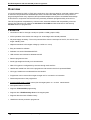
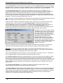
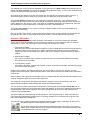
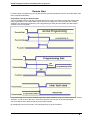
Manual AVR ICP-V24/USB Programmer
AVR ICP-V24/USB
Portable
© Copyright 1998-2002 by E-LAB
Computers
WEB: www.e-lab.de Tel: 07268/9124-0 Fax: 07268/9124-24
E-LAB Computers AVR ICP-V24/USB portable Programmer
Overview
In-Circuit Programming (ISP or JTAG) is the technology of the future at least for small and medium series
of electronic components with embedded processors. At least with SMD parts there is the problem of
programming because many expensive and specialized adapters are required. An additional advantage
of ISP/JTAG in conjunction with the AVR is the practically unlimited reprogrammability of the CPU’s .
This ISP-Programmer emphasizes by minimum size, extensive software and the possibility of remote
control. This manual is only valid for the ICP-V24 and ICP-USB and with restriction for the formerly
ICP-V24 versions of programmers.
Features
• Connection to the PC through a serial port (COM1..COM8) (Option USB)
• ACCU operation of the device with charge unit. Overcharge and overload protected
• No powersupply necessary. The unit is powered direct from the serial port of the PC, the ACCU or the
target. Standby 40uA
• Adapts automatical to the targets voltage (2.7-6Volt ca. 17mA)
• Easy and extensive software
• Software runs under Win98/2000/NT/XP
• USB versions are restricted to Win2000 and XP
• Remote programmer start
• Small, light weight and handy unit 130x70x25mm
• New CPU-types are configurable by the user through ascii text files
• Hexfiles are loaded from PC into the programmer and stored in the ACCU powered SRAM
• CPU type, fusebits etc are selected from the Host/PC.
• Programmer can be moved from target to target w/o PC connection or interaction.
• Password protection of the programmer
• Programmable supply voltage (source) for the target system 2.7..5.2Volt 30mA/100mA
• Self update feature via the PC
• Supports JTAG and SPI programming
• Supports also JTAG Boundary Scan of the target system
• Supports also the whole AT89Sxx family
• Useable as volume production programmer
2 • User Manual AVR ICP-V24/USB portable Programmer
27.05.2003
E-LAB Computers AVR ICP-V24/USB portable Programmer
Connections
Windows-98/2000/NT or XP is required. For USB versions only Win2000 and XP can be used.
V24 Version
The E-LAB programmer must be plugged to any serial interface (COM1 – COM8) of the PC.
The 9-pin plug must be completely connected. A simple wiring of RxD, TxD and GND is not allowed.
Pin7/RTS and Pin4/DTR serve as a powersupply and for ACCU chargeing. In addition DTR generates a
Hardware Reset, when it changed from –10Volt to +10Volt.
USB Version
The included USB cable must be connected to a free USB connector of the PC. The USB drivers must be
installed one time in order to work properly. See the USB section at the end of this manual.
The programmer is supplied with power by an internal 3.6Volt ACCU. The ACCU is charged either by the
serial PC-interface, the target if connected, or the included external powersupply. The charge time from
empty to full is max. 12 hours. The ACCU-voltage is monitored, so an overcharging or a deep discharge is
nearly impossible.
The internal voltage is 3.3Volt. If the voltage of the target exceeds 3.6Volt the supply of the target is used
automatically. Don’t apply high loads at the target pins used for programing. No capcitors are allowed at
these pins. At the reset pin a C/R with max. 100nF/1kOhm is allowed. Lower impedances must be
avoided.
The definition of the 6-pin SPI target plug (0.1 inch pitch male header, dual inline) conforms to a
recommendation from Atmel. The TOP VIEW onto the connector of the Target is below:
CPU MISO(TxD)
o1 2o
VCC
CPU SCLK
o3 4o
CPU MOSI(RxD)
o5 6o
GND
/RES
Attention!
The /PEN pin of the mega64/103/128 has
to be connected to VCC. These megas
use TxD+RxD+SCLK for programming!!
TopView SPI header
Pin1 of the 6pin plug of the programmer can be located by a
small triangle on the front of it. A missalignment of the plug
leads to malfunction and can possibly DESTROY the unit.
The working voltage of the Target CPU must be in the range of
2.7V..5.5V.
None of the control lines of the device must be shortened. A
continous short circuit can destroy the programmer
permamently. Only electrical tested and working boards should
be connected.
JTAG programming
For JTAG programming of the target CPU the 6-wire ribbon cable must be
replaced by 10-wire type. Because the ICP uses the same plug for ISP and
also for JTAG programming the JTAG plug on the target system differs from
the original Atmel JTAG plug. See the schematic on the left.
On the left is the recommended E-LAB plug connection which must be used
for the target system if the JTAG interface of the target AVR must be used for
programming. Please note that the /RESET line is also needed for JTAG.
27.05.2003
User Manual AVR ICP-V24/USB portable Programmer • 3
E-LAB Computers AVR ICP-V24/USB portable Programmer
Programming
Attention: Before the first operation of the unit please charge the ACCU several hours with the
included power supply. Please read the paragraph ACCU-charging!
The device has two buttons, prog/continue and era/clear.
prog button
If both LEDs of the ICP are dark, the device is in powerdown state. It can be wakened by a click
to the PROG button or by connecting it to the PC and start the PC-program AVRprog.exe
The device now processes a memory test and an ACCU check.
The ACCU check measures the ACCU voltage. If it is too low, i.e. the ACCU is empty, the two
LEDs are flashed once one after another. Then the device immediately gets in it’s power down
state. Then it is very important to plug the included ACCU charge supply to the device.
The memory test builds some checksums and compares them with others stored in the memory.
If an error occurs so both LEDs are flashed synchronously on/off. The device now expects a
correct new download of a project from the PC.
If the also the memory check was ok, both LEDs are alternated cyclically (left/right) and the
device is in it’s basic state.
Pressing the prog now starts a programmiing cycle. If the target (CPU) is connected and is
powered like expected, the prog-LED flashes until the process has finished or an error occured.
If the programmiing was successful the device enters it’s basic state which is showed by an
alternate flashing of the two LEDs.
If an error appeared (error code on the left LED) this error must be cleared by the era/clear button
and the device again enters it’s idle state.
In case of an error there are two special cases:
1. A wrong device-ID was read out of the target CPU (2xflash). Because this ID is stored in
EEprom cells in the AVR CPU and this content can be lost under some circumstances this
error (wrong ID) can be ignored and the programming can be continued by an additional click
to the prog/continue button.
2. If the project setup expects that the target system must be powered by the programmer itself
and the error „Target Power Down“ (1xflash) appears, this error can only be removed if the
charging supply is connected to the programmer and the target then is supplied by the
programmer. Furthermore (in this case) the target voltage is checked for the expected value.
A voltage deviation of more then +/-0.2Volt also results in an error.
era button
This button mainly serves to quit an error condition like described above. Secondly a complete
chip erase can be done with the target CPU.
While erase or programming there can be several errors, which are displayed by a count of flashes of the
left LED whilst the right LED is continously on:
1x flash = Device Power down
2x flash = Wrong device/signature (especially with 90S1200)
3x flash = Device protected
4x flash = Device not empty
5x flash = Verify error
4 • User Manual AVR ICP-V24/USB portable Programmer
27.05.2003
E-LAB Computers AVR ICP-V24/USB portable Programmer
Stand-alone
The programmer can be invoked from the Compiler’s IDE (PED32) and also stand-alone by it’s EXE
name. Calling it from the IDE automatically several application parameters (CPU-Type, Clock, Hex-file
etc.) are passed to the programmer.
With Stand-alone (direct call of the EXE by the user) the Project select dialog is opened. A project can be
opened and loaded by a double click onto the desired entry or by a single click onto the entry and an
additional click onto the Load-Button. All project related parameters and files are loaded, so one can start
with a download or the programming.
Display of the project in the
PC
Details of the highlighted
project from the select
window with CPUtype.
Accompanying project
path.
The Flash Hexfile with file
extension.
EEprom file with extension
Store changed or new
project.
Commands
Build a new project
Delete a project
Edit an existing project
Load a project
Search project on network
Exit this dialog.
Build a new project: Click button New. Type the desired name into the fieldProject Name. Click to the
field Directory. From the appearing dialog select the desired directory. Now the dialog for selecting the
file extensions and file types appears. Select/edit extensions and file types. The Flasf file dialog appears.
Select the file which contains the Flash contents. Up to here the selections etc. are a must. The following
dialog for selecting an EEprom file can be ignored, if nothing exists. At last the CPU type must be
selected from the CPU-Select dialog. The new project must be stored by the Save button.
Editing an existing project: Click the button Edit. The program is now in edit mode. With a click onto the
items and fields the accompnying dialog is opens. After all changes are done, store them with a click onto
the Save button.
Dialog for the file types and extensions of a project. These
parameters are project related und must be defined for each
new project.
Edit of an existing project: click Button Edit. By a click to
any edit field a dialog opens. After changing of the project’s
properties the project must be stored with the Save button.
27.05.2003
User Manual AVR ICP-V24/USB portable Programmer • 5
E-LAB Computers AVR ICP-V24/USB portable Programmer
Comment Editor
A right click to an entry in the project
select/load dialog opens this Comment
dialog.
With this dialog it’s possible to add or
view a comment for each project.
Dialog for CPU selection
Device state dialog
After selecting the CPU the clock-frequency of the target must be set. To do this, the button opens
the Device State Dialog. The dialog shows the parameters of the PC-loaded project resp. the
parameters of the hex-files loaded. The parameters and the corresponding hex-files must be transfered
into the ICP-programmer by clicking the Download-button in order to be valid in the programmer.
Editable parameters are located in the Environment box.
The clock defines the SPI speed for ISP programming and can be changed every time. If this value is too
high, the programming can fail. For JTAG programming mode this value has no meaning. But this
parameter should have always the correct value.
The voltage field on the right of it reflects the current voltage value which the ICP programmer measures
on the target board, if connected. The voltage defines the length of the program pulse and by that also the
total programming time (except JTAG programming).
The lower two fields of voltage and current are only visible if a programmer type is connected which has
the feature of supplying the the target with a selectable voltage. The ICP-V24 is such a device.
6 • User Manual AVR ICP-V24/USB portable Programmer
27.05.2003
E-LAB Computers AVR ICP-V24/USB portable Programmer
The current field selects the maximal allowed current to supply. 0.0mA sets the internal supply to the off state.
The other values enable the ICP-internal supply. If a current > 0mA is selected the desired supply voltage can
be selected in the voltage field. If enabled the ICP programmer supplies the selected voltage to the target
system (only in programming state), provided that the ICP’s power supply is connected. The current will be
limited to the selected value.
USB version and power supply
Values > 4.5Volt need an external power supply (6..10V=) which must be connected at the ICP.
Values < 4.5Volt can be directly powered from the USB line.
The field Application shows the actual loaded project in the PC.
The field Programmer shows the information about the connected programmer device: programmer type,
firmware revision and the last firmware update. The last item is important because all update files start with
their date-of-build yy-mm-dd. In the picture above this is 2002, February, 26.
So one can easily find out whether a new downloaded file from the WEB is the same or newer than the one
already downloaded in the ICP. The download of an update into the ICP is described below.
If the portable device ICP is connected to the PC, in the lower field „Download buffer“ the state of the device
internal buffer is displayed.
If the programmer is connected to the PC, the field Download Buffer shows the state of local buffers of the
programmer. An ok means, that the local checksum is valid and because of this also the data. The item Proj:
shows the project name stored in the programmer. The loaded project in the PC is identical with the
programmers project, if it was downloaded by the DownLoad button.
The PC-Software informs the user about differences of the PC’s project and the programmers project every
time an action or command needs synchronousity of the projects. If both projects are the same, also the file
date of the flash file in PC and programmer are compared. If the date in the PC is newer, so a message dialog
informs the user about this.
Notes
Normally the following is true:
All operations interact with the project which is stored in the ICP-programmer and not with the project loaded
in the PC. Because of this it’s absolutely necessary after any changes with the project in the PC to start a
download. Then the state in the PC is synchronized with the state of the ICP!
Protection of the programmer against external short-circuits and over-voltage
All newer programmer types are protected against continous short circuit. The overvoltage protection must be
somewhat limited by such a device and is only allowable for a very short time and low voltages.
The protection consists of a resistor-zenerdiode combination for each control line. The resistor is a 220Ohm
type and is connected between the 10pin ribbon cable header and the internal AVR CPU. The diodes are a
high speed protection diode array of 6Volt types. Each diode is connected to the junction between the resistor
and the CPU pin, the other side is connected to ground. Because of this wiring there can be problems with
programming parts if the target system loads the control lines with low ohm resistance. Also dynamic loads
caused by capacitors can lead to problems.
So it’s a good idea to design system with less or no loads. Resitance below 2kOhm and condensators larger
than 100nF should be avoided in conjunction with the programming lines. This is true for both, the SPIprogramming and also for JTAG-programming.
If it becomes necessary to drive low resistance loads the internal protection resistors (10pin single-inlinenetwork) can be replaced by 5x 50Ohm resistor or short circuits. The resistor network is located directly behind
the 10pin ribbon cable header and is removeable because it has a single-inline socket.
27.05.2003
User Manual AVR ICP-V24/USB portable Programmer • 7
E-LAB Computers AVR ICP-V24/USB portable Programmer
Additional call options
1. Start with the Windows Explorer
If you make a link in the Windows Explorer from the file-extension *.ispe to AVRprog.exe, a double click
to a project-inifile xxx.ispe in the Explorer invokes automatically the AVRprog.exe, which by itself reads
the ini-file and loads the complete project.
2. Start within the E-LAB IDE PED32
The actual version of this software is invoked somewhat different from the older one. To change this the
dialog System Admin must be opened in the IDE PED32. With a click on the list field Prom it’s contents
is copied into the edit field. Here the command must be changed like this:
C:\pppp\AVRProg.exe %Proj
where „pppp“ is the path where „AVRprog.exe“ is located. The following switch %Proj is the change. The
program gets all significant parameters from the project file.
Command line parameters
In principle with all calls of AVRprog switches can be appended. These are:
-com1...-com8 forces the program to use a specific com port regardless of the setup. (non USB types)
-d Automatic Download with the ICP types
-e Automatisches Device erase with all types
-p Automatischer Programming Start with all types
-r Automatischer Target Run with all types
-c Program exit with all types
-s No visual error messages are generated (rev 3.97)
The errors are written into an error file „ICPISP.err“
The order of the switches in the command line don’t matter. The internal processing is always done in the
above order. The switches must be separated by spaces. A switch must not contain spaces.
Example:
C:\pppp\AVRProg.exe %Proj –d –p -c
Iif the switch –p is active, a previous erase (-e) is not necessary because a programming process always
at first erases the target.
If the switch –c is active, a previous Target Run is not necessary because a program exit also releases
the target.
With the parameter %Proj and Stand-Alone operation there are 2 possibilities. One can pass the
complete path and name of the desired control file”ISPE“ like: „%C:files\hex\myprog.ispe“
Or only the name of the project is supplied like: „%myprog“
Networks
Some networks, eg. Novell, use DOS filenames and can not handle the Project File Extension .ispe
This can be solved by changing the corresponding entry in the INI-File of the programmer ISPICP.ini
Example:
[Settings]
ProjExt=.isp
8 • User Manual AVR ICP-V24/USB portable Programmer
27.05.2003
E-LAB Computers AVR ICP-V24/USB portable Programmer
Button-Bar
For fast access of the functions with the mouse the program has a bar with speed-buttons. These allow
fast working without the use of the menues.
|
| |
|
|
| |
| |
|
|
| | |
⇑
|
| |
|
|
| |
| |
|
|
| | |
ICP-Revision ---|
| |
|
|
| |
| |
|
|
| | - display of the remote buffer state
|
| |
|
|
| |
| |
|
|
| ---- display of the actual action
|
| |
|
|
| |
| |
|
|
--- release of the reset of CPU and restart
|
| |
|
|
| |
| |
|
------- ACCU check and voltage of the CPU
|
| |
|
|
| |
| |
----------- abort of the actual action
|
| |
|
|
| |
| --------------- Flash and EEprom Verify
|
| |
|
|
| |
------------------ subsequent Fuse programming
|
| |
|
|
| ---------------------- Flash, EEprom and Fuses programming
|
| |
|
|
------------------------- Chip erase
|
| |
|
----------------------------- State of the programmer and the target
|
| |
---------------------------------- Download of data and parameters
|
| -------------------------------------- flush of the Flash- and EEprom buffer
|
----------------------------------------- reload of the Flash- and EEprom buffer
--------------------------------------------- another resp. new project load
Functions of buttons and menues
Normally the use of the menues is not necessary. All standard operations can be started with the
speedbuttons by a mouse click. Specialized operations can be found only in the menues.
File Menue
Edit/Load Project opens the project dialog. A new project can be
build or an existing one can be opened and loaded or edited.
Save Project parameters stores the project’s current parameters.
Save Flash Buffer to binary File stores the Flash-Buffer into a
binary file. A File-Dialog is opened. Similar is true with Save EEprom
Buffer to binary File.
Save Flash Buffer to Hex File stores the Flash-Buffer into an Intelhex file. A FileDialog is opened. Similar is true with Save Eeprom
Buffer to binary File.
Exit closes the application.
The Projekt-Open button opens the project dialog. A new project can be build or an existing one
can be opened and loaded.
The Reload button loads the previously loaded Hex-Files again.
The Flush button clears the Flash-Buffer and also the EEprom-Buffer completely to $FF
The Device State button opens the Device State dialog. Description see above.
The ACCU button displays the charge state of the accu in the bargraph.
27.05.2003
User Manual AVR ICP-V24/USB portable Programmer • 9
E-LAB Computers AVR ICP-V24/USB portable Programmer
Device Menue
All items/functions of this menu can only be executed if both the programmer and
the target chip are unprotected.
Blank Check tests the target (CPU) for unprogrammed resp. empty.
read back EEprom reads the content of the targets EEprom into the PC’s buffer.
read back Flash reads the content of the targets Flash into the PC’s buffer.
read back All uploads the contents of the Flash and the EEprom to the PC buffers
Verify EEprom compares the content of the targets EEprom to the PC’s buffer.
Verify Flash compares the content of the targets Flash to the PC’s buffer.
Verify All compares the contents of the Flash and the EEprom to the PC buffers
check device checks the programmer and also the target. The above described
Device dialog will be shown.
If any problems they will be displayed. If the CPU is protected only a reaction can be recognized (ID = 00
01 02).
The check button has the same result as the item „check Device“ in the Device Menue above.
Program Menue
program all programs the Flash, the EEprom and also the fuse and lockbits in
the manner defined at Options.
program flash programs the Flash only
program EEprom programs the EEprom only
program Lockbits programs the Lockbits only
erase Device erases the entire chip, Flash, EEprom, fuse and lockbits
erase EEprom erases the EEprom only
erase Fuses erases/programs the fuses to the preset values
edit EEprom is a future extension
A click on the Erase button erases the entire chip inclusive the fuse and lock bits.
The Program button erases the chip completely inclusive the fuse and lock bits. Following the
chip is reprogrammed. The fuse and lock bits are treated as set in Options. Note that the project in
the programmer is used for programmiing and not the project loaded in the PC!
The Security button writes the lock bits which are defined in Options. It is required that the chip is
not protected until this time
The Verify button starts a verify of the target with the buffers, required is an unprotected device.
The Stop button aborts the momentary action.
The Download button transfers all actual parameters and files from PC into the ICP-programmer,
on condition that the ICP is not password protected..
After programming a device the reset stays active (option). The target can be released by a click
to the Run button and again resetted without disconnecting the programmer from the target.
The portable programmer ICP can be remote controlled from PC and also can be controlled without PC
locally by it’s erase and program buttons. An erase is not necessary because the ICP automatically
erases the target before starting programming. Additional functions of the buttons and the status Leds see
below under „State and Errordisplay“.
10 • User Manual AVR ICP-V24/USB portable Programmer
27.05.2003
E-LAB Computers AVR ICP-V24/USB portable Programmer
Options Menue/Dialog
The Options-Dialog controls the behaviour of the programmer at erase resp.
programing of the target. The types of the options depend of the Hex-files
and the selected CPU-type..
If, for example no EEprom-file is loaded, the field „program EEprom“ is disabled.
If the CPU does not support „Fuse Bits“ the field „Fusebits AVR“ is nor visible, otherwise the accessible
fuses are enabled for access. The meaning of the Fuse Bits can be found in the CPU Manual of Atmel.
The field General defines the common behaviour of the unit. The item blank check after erase is only
for testing purpose necessary. Normally it should be disabled.
Program Flash and program EEprom both should be enabled. If there is no EEprom Hexfile present,
the item „program EEprom“ stays disabled constantly.
Ignore false ID disables the error popup in case of a false Device-ID.
Auto release Target releases the the RESET of the CPU automatically after programming.
Kill internal RC-osc erases and writes the desired fusebits inclusive the CKSEL fuses before
programming the chip. In most cases then it’s necessary to have an external quartz connected dependent
of the activated fusebits. Please carefully read the fusebit descriptions of the concrete CPU. The Killoption is only useful if the internal RC-oscillator is active, as shipped with some Tinys and the new mega
series. With JTAG mode this field is meaningless because a working oscillator is not necessary here.
Attention: within the fusebit blocks some CPUs have a SPIEN fuse. This fuse normally is don’t care with
SPI-Low-Voltage programming. But there are also exceptions, the Tiny12 for example. In this case the
SPIEN fuse must be activated. Otherwise the chip is not accessible any more.
The SPIEN fuse is always programmable in the JTAG Mode. If SPIEN and JTAGEN is disabled this CPU
is also not accessible any more.
27.05.2003
User Manual AVR ICP-V24/USB portable Programmer • 11
E-LAB Computers AVR ICP-V24/USB portable Programmer
The item Security defines the lockbits for the protection modes. Program locked is not very meaningful.
Normally there is no protection with item no locks or there is complete protection with program + verify
locked. The exact function and meaning of the fuses should be observed in manuals of the CPU.
The field Fuse bits AVR defines, in case the CPU supports this function, eg. mega128, the fuse
programmable intern Reset time. With other CPU types the internal oscillator or the Brown-Out can be
defined. Because each CPU interpretes these bits in it’s own way it’s impossible make a general
statement here. The field is hidden if the CPU doesn’t support fuses, otherwise the supported fuse bits
can be changed by the user. Unsupported fuse bits are disabled. An empty field means that this option is
disabled = 1. A green ok means that this option is set = 0
Sometimes it is better readable for the designer if not the boolean values of the fuses are shown but
the display shows the binary values. This can be accomplished with this button.
Some CPUs which feature an internal RC-oscillator often have also upto four special read-only fuses
„Calibration byte“, which is shown in the field Calibration Byte. This byte can be used by the
program/application to fine tune the internal RC-oscillator. Because this byte is unique in each CPU it
must be individually passed to the application. A checked checkbox WriteCal Byte forces the
programmer to read this fuse byte and store it into the Flash. The target location of this calibration byte
must be supplied by the user with the help of the dialog „Calibration bytes“ shown below.
Dependent of the CPU type there are upto
4 Calibration Bytes which must be read out
of the CPU. Each byte corresponds with a
unique RC-oscillator. The choice of this
byte (checkbox) is absolutely dependent of
the settings of the CLKSEL-fuses.
With the editfield „address“ the target
address in the Flash for this byte must be
set. With CPUs upto 64kByte Flash size
this can be each value > $0000. With CPUs
> 64kB Flash (mega128) the selected
address must be even.
With newer AVRs and use of the standard RC-oscillator a Calibration Byte handling is not necessary.
These devices automatically read this byte from it’s EEprom memory into the OSCAL register.
Attention: All Fuse and Lockbits are low active. This means if the data sheet shows a zero „0“ for a
specific bit the corresponding field in this dialog must show a green “ok”. Then a log 1 bit must show an
empty field. Atmel always uses negative logic for Fuse and Lockbits!
With the field ComPort the serial interface to use can be selected, if automatic is "OFF". If automatic is
"ON", all eight possible comports are polled until the programmer is found.
The field Reset options defines the controlling behaviour of ICP to the target CPU. Normally all 3 items
are inactiv resp. default. For special target hardware the reset level can be inverted. Push/Pull reset
makes sense if the reset input of the target cpu is burdened by other electronics eg. R/C combination. But
here the loadings must be reduced by a serial resistor of a few kilo ohms. The reset-delay (the time how
long a reset stays inactive before the next activation can take place) can be extended. This is only for
special cases.
The field Programmer Mode is only visible if the selected CPU supports SPI and also JTAG
programming. In this case one of the two modes can be selected.
The Power Supply field selects the maximal allowed current to supply. 0.0mA sets the internal supply to
the off state. The other values enable the ICP-internal supply. If a current > 0mA is selected the desired
supply voltage can be selected in the voltage field. If enabled the ICP programmer supplies the selected
voltage to the target system (only in programming state), provided that the ICP’s power supply is
connected. The current will be limited to the selected value.
12 • User Manual AVR ICP-V24/USB portable Programmer
27.05.2003
E-LAB Computers AVR ICP-V24/USB portable Programmer
The editable fuse- and lock bits are displayed on the right side in the Write column and here they can be
edited. The Read columns can always be updated with the Refresh button. To do this the actual fuse and
lock bits are read out of the target as far as possible.
All changes in this dialogs up to here are always and only relevant for the actual project in the PC. A
download must be forced in order to synchronize the PC’s data with the programmer’s data.
The field ICP params is designed for the automatic PowerDown of the ICP. 1min means that if the
programmer was inactive since one minute the device switches itself into powerdown which reduces the
current drawn from the ACCU to 10uA. This option is immediately stored into the programmer, because
this parameter is project independent. It’s stored into the ICP’s internal EEprom.
The button Erase Fuses is very useful for erasing of illegal FuseBits, which may be activated by an
accidential programming.
One can try with „Erase Fuses“ to set all fuses to the desired value. Some possible error messages can
be ignored in this case. In most cases the CPU then shows a „normal“ behaviour as expected.
Attention (SPI mode):
Some CPU types have an internal RC-Oscillator or the feature to connect an external RC-Oscillator.
These options must be selected by some fuse-bits. Sometimes it’s also possible to select an external
low-frequency quartz. With selecting such an oscillator one must be very careful:
1. Internal RC-oscillator.
With this option selected the standard frequency is typical 1MHz. Because of this the programmer’s
frequency selector must also be set to 1MHz, otherwise there will be errors with accessing the
target CPU. The nominal frequency is 1MHz. With a CPU-voltage of 3Volt the frequency drops to
500kHz.
2. External RC-oscillator.
If this fuse is activated, there must be a proper external circuit connected. Otherwise the target
CPU will be never accessible.
3. Low Frequency Crystal.
If this fuse is activated, a 32kHz watch quartz must be connected to the target. Otherwise the target
CPU will be never accessible.
Please note in addition, that while pogramming, the actual fuses in the CPU are relevant. The new
programmed fuses become valid the first time after a reset. Some fuses become valid the first time after a
power down.
With accidently wrong programmed oscillator fuses it’s possible that after that the external oscillator circuit
must be changed to again get access to the target CPU.
The mega163 is shipped with the internal RC-oscillator enabled. The first access to the chip must
therefore be done with the 1MHz setting! With 3Volts this should be 500kHz.
This can be accomplished without user intervention by checking the checkbox Kill internal RC-osc. In
this case firstly all fuses are set to the desired value with 500kHz. Then the CPU switches to the external
oscillator/quartz which must be present. The following programming now is done with selected CPU
frequency, for example 8MHz.
The above restrictions and warnings are not relevant for JTAG programming. In JTAG mode the CPU
must simply be supplied with voltage/current. A working oscillator is not necessary and is ignored. But
then never disable the JTAGEN fuse.
The settings of the Lockbits (protected/unprotected) and the voltage supply of the target by the ICP are
also displayed in the main program by two symbols.
The padlock means that the target will be locked/protected by the lockbits. The mains or
battery symbol means that ICP must supply the target system. Both symbols belong to the
actual loaded project in the PC program.
27.05.2003
User Manual AVR ICP-V24/USB portable Programmer • 13
E-LAB Computers AVR ICP-V24/USB portable Programmer
Dialog Target Options
This dialog has three jobs:
1. Store/program of additional data into the Flash of the target.
2. Protection of programmer or the targets against unauthorized read back.
3. Counting programmed chips and eventually limit the the count of programmings.
The caption shows the name of the project present
in the ICP.
If a project name is programmed into the target
and it is readable, it is displayed in this panel. The
checkbutton write Name shows the state of this
option.
Serial number in target shows the read back
serial number from the target, if any. The checkbutton write Number shows the state of this option
Serial number in ICP shows the serial number in
the ICP. It’s incremented after every programming
Program devices limited to shows the limitation
of of the programming cycles. The check-button
write Limit shows the state of this option.
CheckSum in target shows the flash check sum in
the target, if present. The check-button write
ChkSum shows the state of this option.
CheckSum in ICP shows the flash check sum
present in the ICP.
In order to change any parameter in this dialog, the correct password must be typed in the password field
and then it must be checked with ?-button with the ICP‘s. Basically the password is empty and a click
onto the button enables the entire dialog. For real password protection a password must be filled into this
field and must be downloaded to the ICP with a click to the flash-button.
From this moment on this password must always be used and must be checked with the?-button. A
password can be removed resp. disabled by enabling this dialog with the correct password and the ?button. Now the flash-button becomes visible. The password field must be cleared now and send with the
flash-button to the ICP. The empty field means that there is no password present and necessary.
Attention: if you forget the password the complete programmer must be erased with the menu item
“Options/Erase ICP”.
Password changing
At first type in the current password into the password field (leave empty if device is new). Now check the
password with the ICP with a click to the ?-button. If password is correct the flash-button appears. Now
type in the new password into the password field. Download the new password with the flash-button into
the ICP.
The password protected device disables the upload or download of files and projects. The Targets can’t
be read out and the maximal programming cycles can’t be changed.
Parameters into the target
If there is enough place in the flash memory of the target cpu additional parameters and informations can
be placed at the end of the flash memory. With the option switches (checkboxes) of the dialog above each
option can be individually enabled or disabled.
A change immediately gets true and is stored into the ICP programmer. An explicit download is not
necessary and is obsolete. Also these options are not stored into the project’s INI-file as usual, but are
14 • User Manual AVR ICP-V24/USB portable Programmer
27.05.2003
E-LAB Computers AVR ICP-V24/USB portable Programmer
only stored into the ICP’s memory. Therefore they are not directly readable or changeable. The options, if
any, are programmed at the end of a programming cycle into last bytes of the target’s flash.
At each invokation of this dialog there is a try to read the nominal-parameters from the ICP and, if
connected, the actual-parameters from the target. The last operation only works, if the target is not
protected, of course. The firmware in the target CPU always has acces to this data.
Project Name into Flash
If the checkbox write Name is activated, the ICP is enforced to write the project’s name into the flash.
This is done at the end of a programming cycle.
Serial Number into Flash
Activating the checkbox write Number instructs the ICP to burn a serial number into the flash. The
integer part of this number is the incremented in the ICP. The serial number consists of 2 parts: 1. Two
arbitrary characters from the field Serial Number in ICP. This part stays unchanged. 2. A number in the
right field. This number can only be be zeroed with the button Reset Number. Preset Number presets
the starting number to the value in the right field. The count of the programmed targets upto now can be
found here.
Programming count limitation
By activating the checkbox write Limit the possible programming cycles are limited. The limit must be
written into the left field. If this count of programmings is exceeded, the ICP programmer does not
program any target anymore. If the deiche is password protected, one must type in the password in order
to cancel this limitation.
CheckSum into Flash
While downloading the flash file, a 16bit checksum is generated over this data. This number is displayed
in the field CheckSum in ICP. This value can be written into the flash by checking the checkbox write
CheckSum. This is done after every programming cycle. Note that the checksum contains only values
from the origin Flash-Hexfile. Additional parameters programmed at the end of the flash by the ICP itself
are not recognized. Also empty (not addressed) parts in the hexfile are discarded.
Reset All
This button resets all values, options and the password and stores them into the ICP.
Note: all changes are immediately stored into the ICP. But they are only recognized at the next
programming cycle.
The application/firmware always has access to this parameters. The parameters are stored into the last
16 resp. 32 bytes of the flash. The project name has a lead-in of „proj“. The serial number has a preamble
of „ser#“. The checksum, if present, always can be found in the last 4 Bytes of the flash, where the last 2
bytes are always „FF“. The order is loByte/hiByte. Sample 8515:
Erase ICP Menu Item
With extremely deep discharged ACCU it’s possible that the data memory of the ICP simply contains
garbage. Afterwards it’s possible the always the message “Programmer protected“ appears. Because of
this it’s a good idea (in case a memory error occued) to use the menu item Erase ICP several times while
ignoring the appearing error messages. Then the dialog Target Options must be opened. With the Reset
all button all parameters must be reset and cleared. Only after this procedure a new download of a project
should be started.
27.05.2003
User Manual AVR ICP-V24/USB portable Programmer • 15
E-LAB Computers AVR ICP-V24/USB portable Programmer
Encrypt Dialog
This menu-item opens the Encrypt Dialog. With the help of this dialog it is possible
to create encrypted binary files, which can be read and processed only with the
included program AVRprogEnc.exe.
This encryption enables the owner
of the sources to send files around
the world and inhibits the receiver or
others to disassemble the hex-file or
do some other re-engeneerings” .
This protects the creators
investments and knowhow.
Furthermore there is the possibility to
limit the count of the chips to
program. This features assures the
owner of the program that only the
desired count of chips or circuits can
be produced. Because of this a
„redirection“ of products for dark
purposes then is impossible.
Procedure
1. Create a project as usual or load an existing project.
2. Select the proper setups and properties for this project as usual.
3. Open the Encrypt Dialog with a click to the menu-item „encrypt project“
4. Define maximal chip count or click the checkbox „unlimited“
5. Choose the proper Password which is valid for the target system (or use the “Public” button)
6. Click the button „Encrypt“
7. Copy the generated file „ProjectName.encr“ to a storage media (floppy etc)
8. If the receiver doesn’t own the program „AVRprogEnc.exe“, also copy this file, the manual
“AVRprogEnc.pdf” and the help file “AVRprogEnc.hlp” onto the media.
9. Ship the media to the receiver.
Shipping this file(s) via email is also possible. In this case it’s a good idea to „zip” all files for secure
internet transport.
Encryption
The encryption feature uses a secure algorithm. Unfortunately upto now there is no absolute secure
(uncrackable) encryption. But the time investment to decrypt the file is so high and expensive, it’s cheaper
and faster to completely start an own program from the scratch ☺
The file „xxx.encr“ can be loaded (means installing) only one time. An additional load is not possible and
will be rejected. If the property „unlimited“ is activated, this is no problem at all.
Limitation
If the programming cycle count is limited, the receiver is enabled to program the defined count of chips or
boards. If the limit count is exceeded the program doesn’t program any chips with this file. A reload or reinstallation of the program or the file „xxx.encr“ doesn’t help. The content of this file can’t be programmed
any more.
The owner of the origin now must provide a new generated “xxx.encr“, so the receiver can proceed with
programming.
16 • User Manual AVR ICP-V24/USB portable Programmer
27.05.2003
E-LAB Computers AVR ICP-V24/USB portable Programmer
Password
With the first run of the program „AVRprogEnc.exe“ on the target system a password is generated which
is derived from some specific data of the target system. This password is only valid for this target system
and is not portable to other systems. Because of this it’s assured that programmer files cantaining this
password can only be programmed on this system. Manipulations of the limit count etc. are then
absolutely inhibited.
Procedure
1. The chip or board programmer must install the programming system AVRprogEnc on this
computers which should be used for programming in the future. To do this the files
„AVRprogEnc.exe“, „AVRprogEnc.pdf“ and „AVRprogEnc.hlp“ must be copied into the desired
directory.
2. The program „AVRprogEnc.exe“ must be started.
3. The program now generetes an unique system dependent password.
4. The password (show with „File/Password“) then must be sent to the owner of the program files.
5. The owner then adds the password in the program „AVRprog.exe“ on his system:
a. Program start of „AVRprog.exe“
b. Start the the Encrypt Dialog with the help of the menu item “encrypt’.
c. Click the button „Add“.
d. Type-in any comment, name or description into the left edit field.
e. The received password must be typed into the right field (8 digits).
f. Store the editing with the button „Add“.
6. With all files which are sent to this receiver which supplied this password, it must be ensured
before clicking the encrypt-button, that the accompanying password is selected. Otherwise the file
is not loadable by the receiver. Alternatively use item 7
7. If the generated file must be accessible for all receivers with different passwords, use the “Public”
button which disables the password if the “Encrypt” button is executed.
Programmer
The program „AVRprogEnc.exe“ only supports the programmer types ICP-I and ICP-V24.
Additional informationen can be found in the manual AVRprogEnc.pdf. This manual also should be sent
to the receiver of the files (also the help file).
27.05.2003
User Manual AVR ICP-V24/USB portable Programmer • 17
E-LAB Computers AVR ICP-V24/USB portable Programmer
Remote Mode
In the production area often it’s necessary to start the programming through a board tester (computer).
From firmware revision 5.7 und up it’s possible to control the ICP-V24 remotely by 2 wires. Then the
supplied 6-wire cable of the ICP-V24 must be replaced by a 10-wire ribbon cable. The signals and
function of the pins 1..6 stay unchanged. The pin7 is used as the remote-state signal (output to the tester)
and the pin8 becomes the remote-start input (controlled by the tester).
All voltage levels must be in the range of the VCC of the target CPU-voltage which is connected to
pin2/VCC. This means that the remote-start input must not exceed 3.3volts, if the target-CPU is powered
with 3.3volts. A voltage greater than CPU-VCC can destroy the programmer, because the internal CPU
runs with the voltage connected to pin2/VCC.
If the test apparature can’t guarantee this, the best way is to use photo couplers for both lines.
The photocoupler OC1 can be replaced by any open-collector driver or by a mechanical switch. With a
switch bouncing should be avoided.
18 • User Manual AVR ICP-V24/USB portable Programmer
27.05.2003
E-LAB Computers AVR ICP-V24/USB portable Programmer
Remote Start
In order to start a programming cycle by the Remote input the programmer must be in the idle state, both
LEDs must flash alternately.
Programmer start by the Remote input
The remote-state output of the ICP-V24 must show a low (0volt). The tester connects the remote-start
input to ground(0V). The remote-state output now rises to a high (vcc). The start input now must be
released. This starts the programming. If the programming is ready and successful, the state output
switches to low (0volt) again.
If a programming error occured, the state output then again switches to high (vcc) after a pause of at least
200msec, in order to show this error. The kind of the error can’t be find out by the state signal.
The error state must be reset and left by a short start-impulse.
By resetting the error by the tester, a new programming cycle can be startet.
27.05.2003
User Manual AVR ICP-V24/USB portable Programmer • 19
E-LAB Computers AVR ICP-V24/USB portable Programmer
Jumper functions
From now on the boards of the incircuit programmer series ICP-I (new name ICP-V24) have two jumpers,
which have the following purpose
Jumper 1
Location:
Function:
Purpose:
Default:
Jumper 2
Location:
Function:
system.
Purpose:
Default:
Not present in the USB types
Besides the SUB-D connector
Connect or disconnect the internal ACCU-charge circuit to the RS232 lines of the PC .
Some PCs, especially the Laptops, have extreme weak RS232 drivers so that the levels
on these lines break down to an unuseable value if the ACCU gets charged throu these
lines. In this case this jumper should be removed to provide error free functuality.
Jumper plugged.
Besides the 10pin ribbon cable header (target)
Connect or disconnect the internal ACCU-charge circuit to the supply of the target
Sometimes the power supply of the target system is too weak to supply the programmer’s
charge circuitry. This is the case if the target is supplied by a button type battery or a
miniature power supply. Here it is necessary to disconnect the programmer’s charge
circuitry from the target’s supply by removing this jumper. If the target-voltage > 3.3Volts,
the programmer’s electronics is still supplied from the target, except it’s charge circuitry.
Jumper plugged.
Opening the case
It’s very simple to open the programmer’s case. With the help of a small screwdriver the two left tongues
at the frontside must be lifted. Then move the cover a bit forward. Now lift the two right tongues slightly.
The cover can be removed now.
Repeat the same process with the backside cover.
Both covers can be clipped to the case in a simple way.
Please don’t forget:
The ACCU must be regular charged.
A deep discharge can destroy the ACCU
20 • User Manual AVR ICP-V24/USB portable Programmer
27.05.2003
E-LAB Computers AVR ICP-V24/USB portable Programmer
ACCU charging
Before the first usage of the ICPs the ACCU must be charged several hours. Connect the power supply
with the small round jack on the frontside of the ICP. The 3.5mm coax plug must have on it’s inner contact
appr. 7..10Volt (max.20mA), the outer part is reference/0Volt.
The ICP-programmer is normally powerd by it’s internal ACCU which capacity is 140mAh. The power
consumption at activation is approx. 12mA. Then the maximal working time is approx. 12 hours. But this is
only a theoretical value. In reality the are 4 possible conditions:
1. The programmer is powered down and unconnected. The current consumption is approx. 40uA. The
self-discharge rate of the ACCU is higher as this value.
2. The ICP is connected to the PC and the PC-Software is connected to the programmer (COMport is
open). The PC-linedrivers supply the ICP. If the programmer is activated, normally this power is high
enough to supply the programmer. In many cases the PC-voltage and current is high enough to
additional charge the ACCUs with a few mA. Here it is necessary that the COMport has been opened
successfully by the PC-software and the programmer was found at this port.
3. The programmer is connected to the target and this part is powered by 5Volt. The ICP is now
supplied from the target and the ACCU is charged with a few milliamperes. If the target’s voltage is at
4Volts or lower the ICP is supplied completely by it’s ACCU and there is no ACCU charging.
4. The programmer is connected to the PC and also to the target. The device which supports the higher
voltage now supplies the ICP. Normally this is the PC.
With a click to the ACCU-button the charge condition of the ACCU can be monitored, but not very
precisely. The ACCU state is displayed by the blue bar in the center of the main window of the PCprogram. A click to the bar removes it.
ACCU supervision
The build-in ACCU is continously supervised. Whilst charging with a constant current of appr.15mA the
ACCU voltage is measured. If the charge-end voltage is reached the system switches to the charge
stabilize current of 1mA. Charging is only possible if the power supply unit is plugged or the ICP is
connected to the PC or target. Note that charging by PC or target in many cases is limited to a few
mAmps dependant of the applied voltage.
If the ICP is activated and the minimal ACCU voltage is reached an error message is send to the PC and
the two LEDs are lighted one after another and then switched off one after another. The ICP itself
switches into PowerDown Mode (40uA) until the next click to Prog-button of the device. Then the ACCU
is checked again for low voltage.
The PowerDown Mode is also started if the predefined time-out has elapsed, this means that the last
activity was back a longer time as the specified time-out. If the ICP is supplied by the target, it will never
switch to PowerDown.
The ICP should not stay connected with a powered down target for a longer time. The programmer
recognizes this and switches to PowerDown, but the target can draw a small current from the programmer
(100..200uA) which empties the ACCU of the ICP.
Power supply
The included power supply serves for charging the ACCU and also as a common supply for the ICP.
Continous charging doesn’t matter because the ACCU is protected against overcharge. If the
powersupply is plugged and working, the ACCU is never overloaded. If the ICP is activated all electronics
is supplied from the powersupply. But then the charge current of the ACCU is limited to 5mA.
The maximal time to charge ACCU from empty state to full state is 12hours.
Alternative supplies
A charge of the ACCU and supply of the ICP can also be accomplished through Pin9/RTS and Pin5/GND
of the 9-pin SUB-D plug (ca. 7..10Volt=).
27.05.2003
User Manual AVR ICP-V24/USB portable Programmer • 21
E-LAB Computers AVR ICP-V24/USB portable Programmer
Status, Errordisplay and problems
Possible error messages of the programming system:
ProgBox not found
a. The programmer is not plugged into the PC’s COMport.
b. The COMports of the PC are all used by other devices.
c. The connection is missing some lines in the cable
Please observe the paragraph Connection
Target Power down
a. The 6pin plug is not connected to the target
b. The target is without power or the voltage is too low ( < 3Volt)
c. The project setup expects that the target is powered by the ICP, but the power supply of the
ICP is not connected or the current consumption of the target is too high.
Device not responding
a. The voltage of the target is too high or too low (see below)
b. Target has no clock (SPI mode only)
c. Chip defective
d. Reset is not connected to the target CPU
Wrong Device ID
a. The voltage of the target is too high or too low (see below)
b. Wrong device selected
c. Chip defective
It is possible that a device ID in the target is permanently destroyed, but the device works correct
If it’s the correct CPU-type the programming can be continued.
All the above problems can also be a problem of a defect programmer. In many cases the loaded Reset
pin causes the problem. An activated Push-Pull Reset option helps.
The ICP-Programmer has 2 additional LEDs, which display the state of the programmer without a PC
Idle:
both LEDs are flashed alternate, no errors
Erasing:
right LED is off, left LED flashes one time
Programming:
left LED is off, right LED is flashes continously (busy)
Errormessages
Memory error:
both LEDs are flashing synchronously. Download error or memory corruption
ACCU empty:
both LEDs are lighted one after another. Then both LEDs are switched off
While erase or programming there can be several errors, which are displayed by a count of flashes of the
left LED whilst the right LED is continously on:
1x flash = Device Power down
2x flash = Wrong device/signature (especially with 90S1200)
3x flash = Device protected
4x flash = Device not empty
5x flash = Verify error
If a CPU shows a wrong device ID at programming, (2x flash) nethertheless one can continue with the
program button or abort with the erase button. Other errors must always be cleared with the erase button.
Known problems at programing of some Atmel AVRs.
The chips can get in an illegal state if the rising of the voltage at power-on is too slow. Sometimes even a
reset can’t clear this state. If this is the case, the temperature of the chip is rising fast.
Problems with USB versions
With correctly installed USB drivers and a valid programmer this Icon
must never appear in the task
bar of Windows, otherwise there are two possible problems.
1. Programmer or USB-HUB defective.
2. Programmer has been supplied with power before it was plugged into the PC. In this case the
programmer must be disconnected from the PC and also the external supply must be removed
(target or powersupply). Then at first connect the programmer to the PC and wait a second until
windows has registrated the plugged device. The similar is true for the switch-on order.
22 • User Manual AVR ICP-V24/USB portable Programmer
27.05.2003
E-LAB Computers AVR ICP-V24/USB portable Programmer
USB drivers
Windows compatibility
For a reliable working with an USB Programmer and a Windows system at least Win98ME is necessary.
Win95, NT3/4 and standard Win98 don’t support USB. Also with Win98ME one must be careful. Not all
versions can handle USB in a reliable way. Because of this E-LAB can not guarantee the functuality of the
USB programmer with Win98ME. So for the USB versions only Win2000 or XP should be used. In
principle hard and/or software development systems should only be operated with Win2000 or XP. These
two systems are very stable now and don’t show the previous problems of restricted resources and
handle count like their predecessors.
Driver locations
E-LAB programmers with USB-interface (like all other non-standard USB devices) need a special USB
driver. This driver is included in the installation.
Each of the four USB types ISP-USB ISP-DEB ICP-USB and ICPII-USB has an own special driver set
which resides in a separate sub directory of the installation directory:
..\ISP-USB-Driver\*.*
driver set for the ISP-USB
..\ICP-USB-Driver\*.*
driver set for the ICP-USB
..\ICPII-USB-Driver\*.*
driver set for the ICPII-USB
..\ISP-DEB-USB-Driver\*.*
driver set for the JTAG-Debugger/Programmer ISP-DEB
In the AVRco compiler installation these drivers can be found in their subdirectories below the directory
..\AVRco\..
Driver installation
The necessary installation of the driver onto a PC is relative simple and without any problems.
But one must proceed in fixed procedure. An USB driver can not be simply installed but must be done in
several steps:
1. Startup the computer and wait until the system is ready for working.
2. The execute the included programmer install program „xxxinst.exe”. The AVRco user simply
starts a new/complete installation of the AVRco system.
3. Plug the USB programmer into a fee USB-port of the PC.
4. Windows now recognizes a new unknown USB device and starts the following procedure:
In the task bar a new icon appears
and on the screen the information below appears.
Then the dialog below opens (New Hardware Wizard)
Now select next by clicking the Next button. The
dialog below appears
Select „Search for a suitable driver“ and click then
Next button
The dialog Locate Driver Files below appears:
27.05.2003
User Manual AVR ICP-V24/USB portable Programmer • 23
E-LAB Computers AVR ICP-V24/USB portable Programmer
Select „specify a location“ and click the Next
button
A file open dialog appears:
Select/change the directory for the programmer
related driver which resides in a sub directory of the
installation directory:
..\ISP-USB-Driver\*.*
driver set for the ISP-USB
..\ICP-USB-Driver\*.*
driver set for the ICP-USB
..\ICPII-USB-Driver\*.*
driver set for the ICPII-USB
..\ISP-DEB-USB-Driver\*.*
driver set for the JTAG-Debugger/Programmer ISP-DEB
In the AVRco compiler installation these drivers can be found in their subdirectories below the directory
..\AVRco\..
Highlight the file FTD2XX.INF and click the Open button. In the following dialog
the choice must be accepted with the OK button.
Windows now checks the driver and releases it for
installation with the following dialog
Continue the installation with a click to the Next
button. After the successful installation of the driver
this dialog opens:
Close the installation with a click to the Finish
button. The dialog disappears and also the icon
disappears from the task bar. Please do not
disconnect the programmer. Shut down Windows.
Now disconnect the programmer from the PC and
restart Windows. If the system is ready again
connect the programmer to the PC. From now on
no visible reaktion of Windows must be seen. Also
the icon must not be shown in the task bar.
Now the programmer is ready for work.
24 • User Manual AVR ICP-V24/USB portable Programmer
27.05.2003
E-LAB Computers AVR ICP-V24/USB portable Programmer
Installing multiple programmers
The E-LAB programmers are individually registered by Windows because each device has it’s own
unique serial number which is used for the registration. If the very first USB programmer becomes
registered now Windows at least knows this version/type of (ICP or ISP) of programmer.
Further new devices normally show this dialog at
the first plug-in and then automatically become
registered. But with some system environment it’s
also possible that Windows requests the
location/path where the driver is located.
De-installing programmer drivers
Basically it makes no sense to de-install drivers for the E-LAB USB programmers because these drivers
are only loaded temporarily if a device gets connected. So the system is not loaded if no device is
connected. But if it becomes necessary to de-install USB drivers this must not be done manually.
Only this driver where the related hardware is connected, can be de-installed. To start de-installation at
first open the device manager of Windows. With the help of this tool the driver can be de-installed. Other
Windows utilities offer a so called deactivating of drivers which has nothing to do with de-installation.
Target Power Supply
All USB programmer have the feature to supply the target CPU with a selectable voltage/current. For this
purpose one can use the charging power suplly included with the ICP/ICPII types. With the ISP types a
external power supply with min 5Volt= and max. 10Volt= and > 100mA must be connected to the power
supply jack. This is true for USB and non USBN units.
Because an USB-port of the PC or HUB also can supply at least 100mA/5Volt= this can be used as an
alternative to a separate power supply. Please note that the official (nominal) 5V in many cases is not 5V
but maybe 4.8V or less for example. Furthermore the device internal voltage regulator also has a drop out
voltage of appr. 0.2Volt. So in the worst case the maximum of the achievable output voltage ist at
4.2Volts.
In addition one must know that an USB port can supply max. 100mA. With the ISP types the programmer
internal current consumption can be upto 20mA. So maximal achievable current to the target can be appr.
80mA. With ICP types the ACCU charge current must be taken in account. With an empty ACCU this can
be 15mA and with a full ACCU this is 1mA.
Multiple programmers
If the PC control program AVRprog.exe finds several
USB programmer or at least one serial and one USB
type are present the programmer must be selected
from this dialog.
Basically only one serial type is searched. If found the
search for these types is aborted.
Regardless how many programmers have been found
only one can be used for working at a time. Gang
programming is not possible.
If additional programmers are connected or disconnected it is
possible to detect the current active with the menu item
File/search programmers.
27.05.2003
User Manual AVR ICP-V24/USB portable Programmer • 25
E-LAB Computers AVR ICP-V24/USB portable Programmer
Firmware Update
Newer programmer devices of the types ISP-V24, ISP-USB, ICP-V24 and ICPII-V24 support the
download of a new firmware into the programmer. Whether your device supports it or not one can find out
with opening the Device Status dialog. Here in the line Update a number appears which shows the
current firmware creation date which is also a part of the update file name.
With a firmware update of the programmer the entire application is deleted and the rewritten with the new
firmware. Only a small bootsector stays unchanged. New firmware for all supplied programmers can be
downloaded from www.e-lab.de. These programs are not executable on the PC but must be handled by
the AVRprog.exe which stores the firmware into the programmer.
Serial/V24 version file: yymmdd_ICP_JTAG.pupd or from WEB in file: ICP_JTAGupdate.zip
USB version file: yymmdd_ICP_USB.pupd or from WEB in file: ICP_USBupdate.zip
This must be done with the menu item Options/Download new Firmware. Please note that all firmware
files must reside in the folder ISP_Updates below the programmer’s home directory which is part of the
ICP/ISP installation. The menu item opens the dialog shown below.
Dialog ISP/ICP Firmware Loader
The group „File state“ contains the
state of the loaded file: filename,
filesize and infos about the
expected target CPU.
The group „Target state“ contains
the state of the programmer.
If the traffic light shows a green the
downloading can be started.
The vertical bar show the download
and programming progress.
The „Open“ button opens a dialog which shows all possible firmware update files. The file names
start with the date of creation and can be easily located. A double click loads the selected file into
the download buffer.
A click to the Comport button then connects the programmer’s download section to the PC’s
downloader. The downloader checks the file against the infos in the programmer. If the file can’t
be accepted an error messages is raised.
If the file fits to the programmer and a connection is established the download can be started with
a click to the phone button. This process can be watched in the progress bar at the dialog’s right
side.
If the downloads „hangs“ so a click to the stop button aborts all.
On problems an increase or decrease of the external ICP voltage can help.
An incomplete download/programming normally is detected at reset or power up of the programmer. If so,
the programmer immediately enters the download state and reclaims a new download. If this occurs the
prog LED of the prorammer is flashed.
It is also possible to force a firmware download. For this purpose there are 2 large solder points next to
the charge control LED. If these two points are shorted together and when the ICP is awakened it
immediately enters it’s download mode and expects a new firmware downloaded by the PC.
26 • User Manual AVR ICP-V24/USB portable Programmer
27.05.2003