1
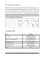
ENIGMA II
Monitoring Receiver
Installer Manual
11 / 02 / 2014
CONTENT
1. INTRODUCTION.......................................................................................................................3
2. SYSTEM STRUCTURE.............................................................................................................3
2.1 CPM card..............................................................................................................................3
2.2 LC telephone line card (optional).........................................................................................4
2.3 RC radio receiver card (optional)..........................................................................................4
2.4 PWR power supply card.......................................................................................................4
2.5 IP card (optional)...................................................................................................................4
2.6 Monitoring software compatibility.......................................................................................5
3. FIRST STEPS..............................................................................................................................5
4. INSTALLATION.........................................................................................................................6
Mounting the receiver unit..........................................................................................................6
Printer connection.......................................................................................................................6
PC connection.............................................................................................................................6
CPM central processing card backside connectors.....................................................................7
PWR power supply card backside connectors............................................................................8
LC telephone line card backside connectors (optional)..............................................................9
RC radio receiver card backside connectors (optional)............................................................10
IP Ethernet receiver card backside connectors (optional).........................................................11
Card installation and replacement.............................................................................................12
5. TECHNICAL DATA..................................................................................................................12
2
1. INTRODUCTION
Thank you for choosing our product. This modern and reliable monitoring receiver not
only guarantees the highest level of security, but also it is a useful colleague in the life
of every monitoring company, because of its user-friendly handling and intelligent
functions.
To use the highest range of provided functions please read carefully the Installer
Manual.
For the confident programming and secure usage please keep all warnings in Installer
Manual, with highly focusing to security directions.
2. SYSTEM STRUCTURE
ENIGMA II monitoring receiver provides complex and reliable solution to build up a
modern monitoring station. The device can receive signals from alarm control panels
through IP network, telephone line and radio channel. Due to the universal operation,
the device can receive all standard (and most of the non-standard) signals from alarm
control panels and communicators. With combination of an appropriate PC-based
monitoring software it guarantees not only reliable signal transmission, but also easy to
use operator interface. The system consists of the following devices:
2.1 CPM card
Central processing card (CPM) which controls the operation of the receiver. CPM
contains two serial ports (respectively 2 high speed USB ports), one Ethernet port and
one parallel printer port. CPM card can store up to 2000 events in its non-volatile
memory. If the connection fails with monitoring computer, the receiver stores events in
its own memory, and all events will be sent automatically when the connection is
restored. CPM controls the graphical LCD display as well, where received events can
be seen and basic settings can be done.
3
2.2 LC telephone line card (optional)
Receiver has 8 slots to connect LC telephone line cards. LC line cards can monitor one
telephone line. Each telephone line card have memory to store up to 500 events or
caller ID. Caller ID function is built in, the caller telephone number is stored and can be
transmitted to monitoring computer. Line cards support two-way audio communication
also. Line cards are continuously monitored by CPM. All line card troubles are displayed
immediately at LCD display, and transmitted to monitoring computer. The line card
monitors the connection with CPM as well, if it detects trouble automatically switches to
standalone operation mode. In this case it continues event receiving, but stores them in
its own memory. All received events will be sent automatically to CPM when the
connection is restored.
2.3 RC radio receiver card (optional)
The optional RC radio receiver card works as a special line card in the system – it
provides event receiving through UHF radio (440..450MHz). RC card can handle two
independent radio channels, which are displayed as line card “A” and “B” in the system.
Event management and CPM monitoring way is similar to LC line cards. In standalone
mode the RC card can store up to 500 events, which will be sent automatically to CPM
when the connection is restored.
2.4 PWR power supply card
PWR power supply card ensures voltage for all cards in the system. The input of PWR
requires 16.5 VAC / 18 VDC, which is generated by an external transformer unit / power
supply unit. PWR has got battery charging circuit, batteries can be connected to
external connectors. In case of main power trouble battery powered operation is
switched automatically. The capacity of batteries should be between 7 Ah and 15 Ah.
The PWR continuously check the state of main power and batteries, and it reports the
status to CPM unit.
2.5 IP card (optional)
Receiver has 8 slots to connect IP Ethernet based receiver cards. IP cards can work in
standalone mode, they control individually the incoming events through Ethernet line.
Then they forward events to central processing unit through internal receiver bus. IP
card gives extended range in IP receiving functions (comparing to CPM). Additionally it
provides possibility to connect the system to a secondary Internet provider.
4
2.6 Monitoring software compatibility
The device can work with the most generally used monitoring software packages.
During development the receiver has been tested with the following software packages:
•
ALARM SYS (recommended), SIMS, MYMAS
SURGARD receiver should be chosen for SIMS, MYMAS or other software types.
3. FIRST STEPS
Please unpack the device carefully and please check is there any damage on that
caused by transport. If there is any obvious damage do not switch on the device, please
call the distributor. The basic package contains the following units:
•
ENIGMA II monitoring receiver (1 CPM card, 1 PWR card)
•
RS232 cable for PC connection
•
USB cable for PC connection
•
16.5 VAC transformer and power cable / 18 VDC power supply unit
•
Battery connector cable (without battery)
•
User Manual
•
Programming Manual
•
Installer Manual
Before mounting the device to its operation environment, receiver test is recommended.
For this connect the external power supply to the PWR card 16.5 V AC terminals and
the battery to the „BATTERY 1 +” and „BATTERY 1 –” connectors.
The receiver
executes a self-test after connecting the power supply and it detects system
components (optional LC line cards, IP cards, RC radio receiver card). After this
operation the event list can be seen on LCD display.
Note: Battery usage is only recommended at BATTERY 1 connector. In special cases
(usage without main power) it is possible to use two batteries (another battery on
BATTERY 2 connector) to provide continuous operation, but is not recommended for
long term usage.
Note: Battery charging voltage can be only measured if the battery is connected.
5
4. INSTALLATION
Mounting the receiver unit
ENIGMA II is manufactured in a 3HE height 19” table housing. In addition it can be
mounted to a standard 19” rack case by means of the holes in front board.
Note: The table stands might be folded up in case of installation to a rack case.
Note: LCD display is planned to be well seen in table usage. If the receiver is installed
over the eye-level, it is recommended to turn a bit downward for better readability.
Printer connection
Any type of parallel printer can be used with Centronics connector. Connect the cable of
the printer to the LPT port of the CPM unit.
Note: In view of the default usage of the device, it is recommended to use matrix printer
as against laser / ink-jet printers for event print.
PC connection
For the connection to monitoring software connect the receiver COM A (USB A) port to
the serial port (USB port) of the monitoring PC. Use the cable provided in receiver
package. If the cable length is not enough, you can use USB expander cable or RS232
expander cable (COM A – 2, 3, 5 pin; PC [9 pin] – 3, 2, 5 pin). With this you may have
up to 10-12 m distance between receiver unit and monitoring PC.
Note: COM A and USB A ports are equivalent, as the COM B and USB B ports. Do not
connect devices at the same time to COM A and USB A ports. If it is possible, always
recommended to use COM A as against USB A.
Note: If the A serial port of the receiver has any trouble, B port can work as a
replacement. For this some small configuration steps are required which can be found
in Programming Manual.
6
CPM central processing card backside connectors
RESET – Hardware reset button.
COM A – Default communication port for PC connection.
COM B – Reserve communication port for PC connection (or for external receiver).
LPT – Parallel printer port.
TCP/IP – Ethernet connector for IP monitoring and for remote programming.
USB A – Default communication port for PC connection (if there is no serial port)
USB B – Reserve communication port for PC connection.
+12 V – Power connector for control functions. Up to 500 mA load capacity.
PGM 1 / PGM 2 – For future usage.
BUZZER – To connect external buzzer (intermittent shortcut with GND during internal
buzzer activation, if the internal buzzer is enabled). Up to 50 mA load capacity.
TAMPER – Works as NO tamper switch if the tamper function is enabled.
EXT. ACK – Works as external acknowledge button (shortcut with GND means manual
acknowledge, same way as ENTER button) if external acknowledge function is enabled.
Note: Install a 10 K pull-up resistor between EXT. ACK and +12 V terminals.
GND – Common GND connector for control functions.
7
PWR power supply card backside connectors
For device installation connect the external voltage to the PWR card 16.5 V AC
terminals and the battery to the „BATTERY 1 +” and „BATTERY 1 –” connectors. The
receiver executes a self-test after connecting the power supply and it detects system
components (optional LC line cards, RC radio receiver card, IP card). After this
operation the event list can be seen on LCD display.
Note: Battery usage is only recommended at BATTERY 1 connector. In special cases
(usage without main power) it is possible to use two batteries (another battery on
BATTERY 2) for continuous operation, but is not recommended for long term usage.
Note: Use only the power supply (18 VDC) / transformer in receiver package (or a
replacement transformer with at least 50VA @ 16.5 VAC capacity).
BAT – 3.15 A – Fuse to protect battery circuit.
AC – 3.15 A – Fuse to protect AC power supply circuit.
BATTERY 1 – Primary battery connector (7-15 Ah).
BATTERY 2 – Secondary battery connector (7-15 Ah).
16.5 V AC – Main power supply connector (18 VDC power
supply / transformer in receiver package or at least 50 VA @
16.5 VAC capacity replacement transformer).
- GROUND – Standard M5 nut for grounding power
supply unit. It is not allowed to use the receiver without
proper grounding.
Note: To provide appropriate protection against electrostatic and electromagnetic
interferences the device housing should be grounded properly. Grounding of housing
and grounding of telephone line cards can be connected only at the common ground
point (at least 2 m distance between each card grounding point – M5 nut / terminals).
Grounding is essential for flash of lighting and over-potential protection, absence of
proper grounding may cause communication problems as well.
Note: Never connect grounding point to receiver GND terminal, it may cause damage.
8
LC telephone line card backside connectors (optional)
LC line card is suitable to receive analog (PSTN) telephone line. Connect the telephone
line into the “LINE/SET” RJ11 connector at the backside of the line card. In case of
ISDN line use one of the analog line outputs of ISDN NT box. For two-way audio
connection the telephone set should be connected to “LINE/SET” connector also. The
incoming telephone line should be connected to the two internal connector interfaces (34), telephone set should be connected to the two external connector interfaces (2-5).
Pay attention that connected telephone set should be in line, as if it is in hanged up
state the two-way audio connection doesn't work. Check device impedance as well – it
should be 600 ohm for normal phone sets.
LINE / SET – Analog telephone line connector.
– GROUND – Terminals to connect telephone line card
(into either of connectors).
Note: Grounding of housing and grounding of telephone line cards can be
connected only at the common ground point (at least 2 m distance
between each card grounding point – M5 nut / terminals). Grounding is
essential for flash of lighting and over-potential protection, absence of
proper grounding may cause communication problems as well.
9
RC radio receiver card backside connectors (optional)
RC radio receiver card can handle two independent radio channels. Channel “A” is
usually supplied with built in radio (or external radio for special request). Channel “B”
only can be used with an external radio unit. If the channel “A” is supplied with built in
radio (RTX 2U2), only the antenna should be connected to “ANT” connector. Pay
attention for using UHF antenna with suitable end of line resistor (50 ohm), and the RF
cabling should have minimal loss.
Note: If you want to use channel “B” with external radio unit, please contact your
distributor.
RSP – Radio serial port for programming without
CPM (radio repeater stations), and for debugging.
ANT – Antenna connector for built in radio units
(channel „A”).
Note: Always
choose
the
appropriate
antenna
according to the installation site of the receiver.
RADIO 2: External radio connector (for channel „B”).
RADIO 1: For special request channel „A” might be
supplied with external radio unit.
10
IP Ethernet receiver card backside connectors (optional)
IP receiver cards are able to receive events through Ethernet network. IP card has
extended IP receiving functions compared to CPM unit in main receiver. Connect the
Ethernet network cable into the Ethernet slot on the receiver card backside. If it is
required, the IP card can be connected directly to monitoring PC through USB
connector on receiver backside.
LAN – 100 Mbit Ethernet network connector
USB – To connect monitoring PC (if it is required)
11
Card installation and replacement
Receiver switch off is not required during card replacement. Unscrew the two / four
fixing screws, then pull the card carefully with a firm action. New card installation is the
same, only in opposite sequence. Before installing new LC / RCM / IP card, please
remove the metal cover from the card position. CPM / PWR / RCM cards have fix
position, LC / IP card can be mounted into 1 – 8 slots (starting from slot 1 if possible).
Note: Do not forget to apply / set again previous settings (before change) in new cards.
Note: If there is any malfunction after card replacement, please restart the device with
F3 (UTIL) / F3 (RESET / F3 (RESET) buttons.
5. TECHNICAL DATA
Product
ENIGMA II
Power supply
18 Vdc @ 2 A (main) or
16.5 Vac @ 30 VA (main) /
12 Vdc @ 7 Ah (battery)
Maximum current consumption
about 500 mA
(depends on configuration)
Event buffer
up to 2000 events
Monitored IP devices
up to 255 accounts
Operating temperature
10 °C / +30 °C
40% relative humidity
Sizes (W / L / H)
485 x 220 x 135 mm
Weight
5200 g
12