1
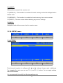
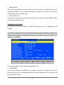
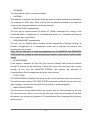
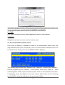
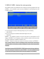
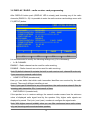
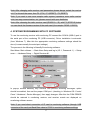
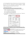
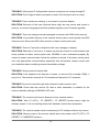
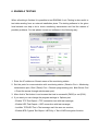
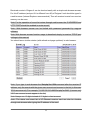
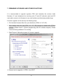
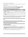
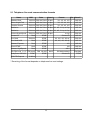
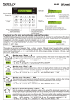
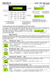
ENIGMA II
Monitoring Receiver
Programming Manual
6 / 11 / 2014
CONTENT
1. INTRODUCTION.......................................................................................................................3
2. SYSTEM STRUCTURE.............................................................................................................4
2.1 CPM card..............................................................................................................................4
2.2 LC telephone line card (optional).........................................................................................4
2.3 RC radio receiver card (optional)..........................................................................................5
2.4 PWR power supply card.......................................................................................................5
2.5 IP card (optional)...................................................................................................................5
2.6 Monitoring software compatibility.......................................................................................5
3. SYSTEM PROGRAMMING FROM RECEIVER MENU.........................................................6
3.1 F3 (UTIL) menu....................................................................................................................7
3.2 F4 (SETUP) menu.................................................................................................................8
3.3 IP communication status menu...........................................................................................13
3.4 DISPLAY – card programming and status checking..........................................................14
3.5 DISPLAY / CARDS – telephone line card programming...................................................15
3.6 DISPLAY / RADIO – radio receiver card programming....................................................16
4. SYSTEM PROGRAMMING WITH PC SOFTWARE.............................................................17
5. TROUBLESHOOTING.............................................................................................................19
6. ENIGMA II TESTING..............................................................................................................21
7. FIRMWARE UPGRADE AND OTHER FUNCTIONS...........................................................23
8. SYSTEM MESSAGES..............................................................................................................26
9. COMPATIBILITY.....................................................................................................................28
9.1 Telephone line card communication formats......................................................................29
2
1. INTRODUCTION
Thank you for choosing our product. This modern and reliable monitoring receiver not
only guarantees the highest level of security, but also it is a useful colleague in the life
of every monitoring company, because of its user-friendly handling and intelligent
functions.
To use the highest range of provided functions please read carefully the Programming
Manual.
For the confident programming and secure usage please keep all warnings in Installer
Manual, with highly focusing to security directions.
3
2. SYSTEM STRUCTURE
ENIGMA II monitoring receiver provides complex and reliable solution to build up a
modern monitoring station. The device can receive signals from alarm control panels
through IP network, telephone line and radio channel. Due to the universal operation,
the device can receive all standard (and most of the non-standard) signals from alarm
control panels and communicators. With combination of an appropriate PC-based
monitoring software it guarantees not only reliable signal transmission, but also easy to
use operator interface. The system consists of the following devices:
2.1 CPM card
Central processing card (CPM) which controls the operation of the receiver. CPM
contains two serial ports (respectively 2 high speed USB ports), one Ethernet port and
one parallel printer port. CPM card can store up to 2000 events in its non-volatile
memory. If the connection fails with monitoring computer, the receiver stores events in
its own memory, and all events will be sent automatically when the connection is
restored. CPM controls the graphical LCD display as well, where received events can
be seen and basic settings can be done.
2.2 LC telephone line card (optional)
Receiver has 8 slots to connect LC telephone line cards. LC line cards can monitor one
telephone line. Each telephone line card have memory to store up to 500 events or
caller ID. Caller ID function is built in, the caller telephone number is stored and can be
transmitted to monitoring computer. Line cards support two-way audio communication
also. Line cards are continuously monitored by CPM. All line card troubles are displayed
immediately at LCD display, and transmitted to monitoring computer. The line card
monitors the connection with CPM as well, if it detects trouble automatically switches to
standalone operation mode. In this case it continues event receiving, but stores them in
its own memory. All received events will be sent automatically to CPM when the
connection is restored.
4
2.3 RC radio receiver card (optional)
The optional RC radio receiver card works as a special line card in the system – it
provides event receiving through UHF radio (440..450MHz). RC card can handle two
independent radio channels, which are displayed as line card “A” and “B” in the system.
Event management and CPM monitoring way is similar to LC line cards. In standalone
mode the RC card can store up to 500 events, which will be sent automatically to CPM
when the connection is restored.
2.4 PWR power supply card
PWR power supply card ensures voltage for all cards in the system. The input of PWR
requires 16.5 VAC / 18 VDC, which is generated by an external transformer unit / power
supply unit. PWR has got battery charging circuit, batteries can be connected to
external connectors. In case of main power trouble battery powered operation is
switched automatically. The capacity of batteries should be between 7 Ah and 15 Ah.
The PWR continuously check the state of main power and batteries, and it reports the
status to CPM unit.
2.5 IP card (optional)
Receiver has 8 slots to connect IP Ethernet based receiver cards. IP cards can work in
standalone mode, they control individually the incoming events through Ethernet line.
Then they forward the events to central processing unit of main receiver through internal
receiver bus. By means of IP cards gives extended range in IP receiving functions
(comparing to CPM card in base receiver unit). Additionally it provides possibility to
connect the system to a secondary Internet provider.
2.6 Monitoring software compatibility
The device can work with the most generally used monitoring software packages.
During development the receiver has been tested with the following monitoring software
packages:
•
ALARM SYS (recommended)
•
SIMS
•
MYMAS
5
SURGARD receiver should be chosen in case of SIMS, MYMAS or other monitoring
software types.
3. SYSTEM PROGRAMMING FROM RECEIVER MENU
After completing instructions from Installer Manual it is time to start ENIGMA II
monitoring receiver programming. The main settings can be done through the receiver
menu displayed on LCD.
The starting display, LED signals of monitoring receiver, and the functions without user
code are shown in User Manual.
09:17:46
ACCOUNT EVENT
5451
5451
5451
5451
5451
LINE
CLOSING
BURGLARY
ZONE RESTORE
OPENING
CANCEL
01 001
01 005
01 005
01 001
01 001
IP
IP
IP
IP
IP
TIME
11:35:37
11:45:22
11:45:24
11:50:39
11:50:40
FONT
CODES
UTIL
SETUP
F1
F2
F3
F4
After turning on the receiver and system boot the display above is shown on LCD
screen. F1 – F4 buttons (there is the assigned function above each button) can be
used for navigation in menu, and they can be used also to execute functions which are
protected with password (and not mentioned in User Manual).
Note: After the first start of the device it is always recommended to apply default
settings: F3 (UTIL) / F3 (RESET) / F1 (DEFAULT).
Default password for menu access: ENIGMA
Note: It is strongly recommended to change default password with EniTerm software.
6
CONSOLE
VER: CPM2.60.BC06
ENTER PASSWORD
[ *█
]
ABCDEFG
HIJKLMN
OPQRSTU
VWXYZ_ –
F1
F2
F3
F4
Code entering is possible by choosing characters with F1 – F4 buttons (more pushes of
one button can be used to change character, backspace is with ◄ button, code apply
with ENTER button, exit with DISPLAY button). After code entering it is allowed to enter
into receiver menu (without entering the code again) for 3 minutes since the last button
pushing .
3.1 F3 (UTIL) menu
REPORT
PRINT
RESET
BACK
F1
F2
F3
F4
F1 (REPORT)
To resend receiver memory stored events to monitoring software.
F1 (LAST 50) – To resend last 50 events to monitoring software.
F2 (TODAY) – To resend all events from the last day to monitoring software.
F3 (ALL) – To resend all receiver events to monitoring software.
F2 (PRINT)
If printer is connected, events stored in receiver memory can be printed.
F1 (LAST 50) – To print last 50 events.
F2 (TODAY) – To print all events from the last day.
F3 (ALL) – To print all receiver events.
7
F3 (RESET)
Different level resets of the receiver unit.
F1 (DEFAULT) – This function is to delete full event memory and set all settings back to
default value.
F2 (MEMORY) – This function is to delete full event memory, then receiver restart.
F3 (RESET) – Receiver restart without deleting any events / settings.
F4 (BACK)
Navigation back with one menu level in receiver menu.
3.2 F4 (SETUP) menu
OPTIONS
PORTS
TIME
BACK
F1
F2
F3
F4
F1 (OPTIONS)
CONSOLE
VER: CPM2.60.BC06
CPM OPTIONS
BUZZER OPERATE
YES
+
–
PAGE
CANCEL
F1
F2
F3
F4
First choose the option to configure with ◄ and ► buttons (chosen value is blinking).
For changing the value you can use F1 (+) and F2 (–) buttons. You can apply settings
with ENTER button.
It is recommended to modify the following settings only:
8
•
BUZZER OPERATE
YES – ENIGMA II buzzer is on, yo can hear buzzer sound if there is new event until
manual acknowledge (pushing ENTER button) / monitoring software acknowledge.
NO – ENIGMA II buzzer is off, there is no buzzer signal in case of unacknowledged
event.
F2 (PORTS) / F1 (COM A) or F2 (COM B)
CONSOLE
VER: CPM2.60.BC06
SERIAL PORT A
OPERATION MODE
RECEIVER ID
PORT SETTING
NORMAL
01
9600, 8, NONE
+
–
PAGE
CANCEL
F1
F2
F3
F4
It is recommended to modify the following settings only:
•
OPERATION MODE
NORMAL – ENIGMA II forwards data on the given port towards monitoring software
(default port for PC connection).
RECEIVE – ENIGMA II can only receive data on the given port (this port is to connect
another receiver to ENIGMA II, or for reserve port).
Note: COM A and USB A ports are equivalent, as the COM B and USB B ports. Do not
connect devices at the same time to COM A and USB A ports. If it is possible, always
recommended to use COM A as against USB A.
Note: If the A serial port of the receiver has any trouble, B port can work as a
replacement. For this switch on OPERATION MODE to RECEIVE on port A, and to
NORMAL on port B. Please connect PC connector from port A to port B.
9
•
RECEIVER ID
The option has importance when there are more receivers connected to the same
monitoring software. If each receiver has different number, in event list it can be seen
which receiver sent the given event.
•
PORT SETTING
You can check the actual serial port settings in this menu. Default values: 9600 (speed),
8, NONE (Data Bits & Parity)
F2 (PORTS) / F3 (TCP/IP)
In this menu you can configure the main monitoring receiver IP parameters and
settings.
Note: After changing all kind of IP parameters please always restart the receiver unit (if
restart doesn't happen automatically. For this exit the menu, then F3 (UTIL) / F3
(RESET) / F3 (RESET).
CONSOLE
VER: CPM2.60.BC06
TCP/IP OPTIONS
IP ADDRESS
NETMASK
GATEWAY
RECEIVE PORT
PROGRAM PORT
IP MONITORING
MONITOR PERIOD
CID TEST EVENT
WEB HTTP PORT
WEB PASSWORD
192 168 001
255 255 255
000 000 000
270F (09999)
0017 (00023)
OFF
05A0 (01440)
16A3
0050 (00080)
NO
240
000
000
TEST FILTER
LINES
OFF
024
+
–
PAGE
CANCEL
F1
F2
F3
F4
It is recommended to modify the following settings only:
•
IP ADDRESS
Here you can define the ENIGMA II unit private (internal) IP address in local area
network. Take care to not use address which is used by another device, or which can be
given by DHCP service.
10
•
NETMASK
The used subnet mask in local area network.
•
GATEWAY
This address is required if the device optionally wants to realize external communication
(for example for WAN Test). Most of the times the gateway address is the same as
rooter private (internal) address in local area network.
•
RECEIVE PORT (hexadecimal)
The port can be defined where IP based (IP, GPRS) messages are coming to the
monitoring station. Configuration is in hexadecimal mode, but in brackets the decimal
port number also can be seen.
•
PROGRAM PORT (hexadecimal)
The port can be defined where receiver remote programming (through Internet) is
possible. Configuration is in hexadecimal mode, but in brackets the decimal port
number also can be seen.
Note: For the operation of remote programming the IP ADDRESS and PROGRAM
PORT should be enabled in rooter as well (Port Forward / Virtual Server / NAT in rooter
menu).
•
IP MONITORING
If this option is enabled, the first 255 (from receiver startup) user accounts received
through IP channel will be monitored. If there is no event with the given user account
through IP line until the MONITOR PERIOD, the receiver will generate IP
Communication Error message with the given client account.
•
TEST FILTER
If IP MONITORING is enabled, this option can be used to filter test code by the receiver.
The defined event codes in CID TEST EVENT menus will be filtered, the first test event
after midnight / receiver start (for each user accounts) is always displayed.
•
MONITORING PERIOD
The time period can be defined within the receiver wait IP communication for the first
255 user accounts. If there is no event with the given user account through IP line until
this period, the receiver will generate IP Communication Error message with the given
client account.
11
•
CID TEST EVENT
The test event code can be defined for CID communication. '0' character is displayed as
'A' character.
•
WEB HTTP PORT (hexadecimal)
The device provides access for event list review through web browser. For this function
this port should be configured. If you use different port as default 80, for view event list
you should type the port as well after the IP address / domain name.
Note: For the operation of event list review through web browser the IP ADDRESS and
WEB HTTP PORT should be enabled in rooter as well (Port Forward / Virtual Server /
NAT in rooter menu).
Note: It is recommended to Internet Explorer 8 or higher for event list review.
Note: Take care to not use ports which might be used by another device (for example:
110 port).
•
LINES
When you use web browser to event list review, here can you define that how many
events are displayed in one page.
•
WEB PASSWORD
NO – No password is required for event list review in web browser.
YES – Password is required for event list review in web browser.
Note: The password for event list review is not the same as the ENIGMA II password.
Web browser access password can be created by means of wpg.exe software. For this
it is necessary to define the client account (which can be seen by the generated
password; All = Access to all accounts), the validity period of the generated password
(Unlimited = No limit for validity), and the ENIGMA II password is also needed for web
browser password generation.
12
Note: After changing all kind of IP parameters please always restart the receiver unit.
For this exit the menu, then F3 (UTIL) / F3 (RESET) / F3 (RESET).
F3 (TIME)
Date and time setting (function without password), details in User Manual.
F4 (BACK)
Navigation back with one menu level in receiver menu.
3.3 IP communication status menu
From event list display it is possible to switch to IP communication status menu with
long DISPLAY button push (3 seconds). Lots of IP communication related function can
be checked here. During menu access DISPLAY LED is flashing.
CONSOLE
VER: CPM2.60.BC06
CPM STATUS
IP : ON (FC4)
SCK : 001/255
TCM : 004/255
192 . 168 . 000 . 240 09999
255 . 255 . 255 . 000 00023
192 . 168 . 000 . 001 00080
081 . 182 . 170 . 247 OK
––––––––––––––––––––––––––––––––––––––––––––––––––––––––––
5451 UPDATE 00005 14AA . .
5451 UPDATE 00005 16A2 x .
The following data can be seen: Receiver LAN IP address – Receive port; Netmask –
Remote programming port; Gateway – Web browser access port; Public IP – WAN
monitoring status. SCK = Opened sockets number, TCM = IP monitored device number.
In appearing events first digits are the client account (5451), then the IP monitoring
period (00005), and at the end there is the event code (14AA).
13
3.4 DISPLAY – card programming and status checking
After pushing the DISPLAY button (DISPLAY LED lights continuously) you can enter
into the following window:
CARDS
1
2
3
4
5
6
7
8
RADIO
OK
OK
-------------------------
16:48:17
_ A OK
I████████
B ----I
USB A
LPT
AC
OK
––
OK
COM-B
IPLINK
BATTERY
R
OK
OK
1 : OK
MON OFF
SETUP
STATUS
HANG UP
F1
F2
F3
F4
CARDS – Telephone line cards / IP cards status
READY – Telephone line card / IP card is OK.
RING – Ring on telephone line card.
INCOMING CALL – Telephone line card received the incoming call (incoming event
codes can be seen).
TEL LINE ERROR – Card is OK, but line has trouble.
ID: xxx – Call is from xxx phone number.
RADIO – Radio receiver card status
OK – Radio receiver card OK (signal level scale below).
Event codes can be seen during radio receiving, received signal strength in brackets (7
– minimum, F – excellent).
F1 (MON ON / OFF) – Speaker On / Off.
F3 (STATUS) – Card status (and firmware version checking, RESET button for card
restart.
F4 (HANG UP) – To abort stucked phone call.
14
3.5 DISPLAY / CARDS – telephone line card programming
After DISPLAY button push (DISPLAY LED is steady) and choosing telephone line card
(CARDS 1 – 8) it is possible to enter the chosen telephone line card settings menu with
F2 (SETUP) button.
CONSOLE
VER: CPM2.60.BC06
CARD 1 OPTIONS
HSK LENGTH
CALLER ID
120
ENABLE
+
–
PAGE
CANCEL
F1
F2
F3
F4
It is recommended to modify the following settings only (if it is necessary):
•
HSK LENGTH
Here you can change the Handshake and Kissoff length of line card.
•
CALLER ID
ENABLE – The telephone numbers of the call to the given line card appears on LCD
display of ENIGMA II unit (if telephone number sending is enabled at service provider
and 'Caller ID Message' is enabled in Enigma II unit).
DISABLE – Telephone numbers from the given line card are not shown on ENIGMA II.
Note: Function might be useful for debugging during communicator connecting to
monitoring station, as the phone number is displayed in case of bad communication
format too.
Note: Before changing HSK SEQUENCE / TIMING always consult with your distributor.
Note: After choosing the telephone line card (CARDS 1 – 8), with F3 (STATUS) button
you can check the firmware version of the line card (for example: LC-2.20.BA14).
15
3.6 DISPLAY / RADIO – radio receiver card programming
After DISPLAY button push (DISPLAY LED is steady) and choosing any of the radio
channels (RADIO A – B) it is possible to enter the radio receiver card settings menu with
F2 (SETUP) button.
CONSOLE
VER: CPM2.60.BC06
CARD R OPTIONS
A–CHANNEL
RECEIVER
– CONFIGURATION RECEIVER
1–WAY
– HOME SYSTEMS 01 01 01 01 01 01 01
– SWR DISPLAY
18 40 90
B–CHANNEL
DISABLE
– CONFIGURATION RECEIVER
1–WAY
– HOME SYSTEMS 01 01 01 01 01 01 01
– SWR DISPLAY
18 40 90
REPEATER ID
1F40
SAME
01
SAME
01
+
–
PAGE
CANCEL
F1
F2
F3
F4
It is recommended to modify the following settings only (if it is necessary):
•
A / B CHANNEL
ENABLE – Radio channel can be used for radio receiving.
DISABLE – Radio channel can not be used for radio receiving.
Note: By default channel A contains the built in radio receiver unit, channel B works only
if you connect an external radio to that.
•
HOME SYSTEMS (hexadecimal)
Here you can define that which radio transmitter identifiers are received by the radio
channel. There are 8 different identifiers to set.
Note: If you type 00 identifier to any of the positions, the radio receiver doesn't filter the
incoming radio transmitter IDs, it receives all of them.
•
SWR DISPLAY (hexadecimal)
If the speaker is on in receiver settings, the second number means here the minimum
value of displayed radio signal level by the speaker. Only higher radio signals are
displayed by sound. First (min.) and (max.) numbers to configure the signal scale.
Note: With higher second (middle) value you can filter continuous lower radio noises,
only real incoming radio events activates speaker.
16
Note: After changing radio receiver card parameters please always restart the receiver
unit. For this exit the menu, then F3 (UTIL) / F3 (RESET) / F3 (RESET).
Note: If you want to use more complex radio system (repeaters, more radio receiver
units, two-way communication, etc.) please consult with your distributor.
Note: After choosing the radio receiver card (RADIO A – B), with F3 (STATUS) button
you can check the firmware version of the radio card (for example: RCM2.11.B223).
4. SYSTEM PROGRAMMING WITH PC SOFTWARE
To use the monitoring receiver with monitoring PC connect the COM A (USB A) port to
the serial port of the monitoring PC (USB connector). Driver installation is automatic
(from Windows 7). After this the appropriate monitoring software settings should be
done (it means usually the serial port settings).
The process is the following in AlarmSyS monitoring software:
Start Alarm Start software → Start Alarm Setup and log in (ID: 1, Password: 1) → Setup
menu → Hardware Setup → Digital Receiver #1.
In pop-up window basically only Receive and process incoming messages option
should be enabled, then set the proper COM port (checking in Windows OS: Control
Panel / Hardware / Device Manager), then apply changes. After this the COM ERROR
should be restored in monitoring receiver, and receiver events are displayed on
monitoring software screen.
Note: If you need direct connection of IP card to monitoring software (through USB
connector of the card) set Baud Rate value to 57600 in monitoring software settings.
17
In normal case programming of the monitoring receiver unit can be done in serial port
(any of the COM ports or USB ports). After completing appropriate IP settings
programming can be done through Ethernet network as well. Please use EniTerm
software for programming. The programming steps are bellow:
1. Please start EniTerm software.
Note: PC programming provides access for all system parameter settings.
2. Choose the ET (settings) file according to the device what you want to program:
- CPM.et – CPM (receiver) programming
- LC.et – LC (telephone line card) programming
- RC.et – RC (radio receiver card) programming
- IP.et – IP Ethernet receiver card programming
3. In Communication / Port Settings menu set the communication port / IP address for
programming.
4. With Communication / Read Data menu you can read stored settings from receiver.
Note: Before reading LC telephone line card data, you should select number of the line
card in the pop-up window.
The highlighted firmware version means
the following (hexadecimal format):
C – 12 (2012)
A – 10 (October)
02 – 2 (Second day)
18
5. Please execute the required settings in EniTerm software.
Note: The software functions are shown in EniTerm help menu.
6. Click to Communication / Write Data menu to send the modified settings to receiver.
Note: Before reading LC telephone line card data, you should select number of the line
card in the pop-up window.
Note: During data reading (and sending) CPM firmware version can be checked.
5. TROUBLESHOOTING
TROUBLE: Any abnormal operation in functions during the usage of the device.
SOLUTION: Firmware upgrade with the newest firmware file usually solve these kind of
problems (see Firmware update part in manual).
TROUBLE: Receiver unit restarts or freezes without any reason when touching device
housing or LCD display, or when push any receiver button.
SOLUTION: Receiver grounding is not connected (properly), so the electrostatic
charges causes these problems. Use the device only with appropriate grounding. Usage
without grounding may cause the device and it is not warranty problem.
TROUBLE: No connection between monitoring PC and receiver unit (COM ERROR).
SOLUTION: Check the cable plugging in PC side and in receiver side as well. In
monitoring PC Control Panel / Hardware / Device Manager application you can check
which COM port appears / disappears in device list during plug / unplug ENIGMA II
cable. Please check whether COM port setting is correct in monitoring software.
19
TROUBLE: After proper IP configuration receiver events are not coming through IP.
SOLUTION: Don't forget to allow used ports in rooter (Port forward menu in rooter).
TROUBLE: Event names are missing, or not correct in receiver display.
SOLUTION: Because of the new functions there might be new menus and events in
receiver, so receiver language should be updated regularly (see Firmware upgrade).
TROUBLE: There are strange internal messages in receiver with 0000 client account.
SOLUTION: It is possible that any of the external device (alarm control panel) has 0000
client account. Never use 0000 client account in alarm control panel side.
TROUBLE: There is Fault call on telephone line card message on display.
SOLUTION: Basically it is not error, it means only that the format of communication has
some problem at alarm control panel side, ENIGMA II can't understand properly. By
means of proper communication format the problem is solved. If the alarm control panel
can't use appropriate communication (especially with old panels), please consult with
your distributor about modifying receiver handshake settings.
TROUBLE: Wrong received events data.
SOLUTION: If the telephone line has lots of noises, or low level (for example: GSM), it
may occur. The receiver converts all 'A' hexadecimal character to '0' character.
TROUBLE: No event comes through radio channel to radio receiver card.
SOLUTION: Check that the receiver ID used in radio transmitter is suitable for the
receiver identifier settings in ENIGMA II RC card.
TROUBLE: The receiver unit freezes because of any external reason.
SOLUTION: With F3 (UTIL) / F3 (RESET) / F3 (RESET) buttons there might be
software restart, if it is not working restart with hardware reset button (backside).
TROUBLE: The receiver sends events continuously to PC software without any reason.
SOLUTION: Memory reset of the receiver should solve the problem with F3 (UTIL) / F3
(RESET) / F2 (MEMORY) buttons.
20
6. ENIGMA II TESTING
When all setting is finished it is possible to test ENIGMA II unit. Testing is also useful to
test data sending from an external installation place. The testing software in the given
local network can help a lot to check monitoring transmission and find the reason of
possible problems. For test please use ipt.exe software in the following way:
1. Enter the IP address or Domain name of the monitoring station.
2. Set the ports for communication with monitoring station (Receive Port = Monitoring
transmission port; Shell (Telnet) Port = Remote programming port; Web Server Port
= Event list access through web browser port).
3. After click to Test button it can be seen that test is successful (PASS) or not (FAIL).
4. If you want you can change the program settings in Options part:
- Enable TCP Test Report = TCP connection test with test message;
- Enable UDP Test Report = UDP connection with test message;
- Invisible TCP/UDP Test = Test message can't be seen on receiver;
- Enable AES Crypted Test Report / AES Key = Test of AES encryption function.
21
Received events in Enigma II can be checked easily with a simple web browser access.
For this IP address (and port if it is different from 80) of Enigma II unit should be typed in
a web browser (Internet Explorer recommended). Then all received events from receiver
memory can be seen.
Note: For the operation of event list review through web browser the IP ADDRESS and
HTTP PORT should be enabled in rooter as well.
Note.: Web browser access can be limited with password generated by wpg.exe
software.
Note: Web browser access function usage is described deeply in receiver TCP/IP port
settings in this manual.
You should see a similar window (with refresh and page up/down) in web browser:
Note: If you type in web browser the /list.php?a=1234 command after the receiver IP
address, only the events with the given user account can be seen in the list (in this case
1234 user account). For example: 74.125.232.210:8800/list.php?a=54A5 (it means only
5405 user account events appear in the list).
Note: Always use 'A' digits instead of '0' digits in client account.
Note.: The status and event list of IP Ethernet receiver card can also be checked
through web browser after typing the IP address of the card.
22
7. FIRMWARE UPGRADE AND OTHER FUNCTIONS
It is recommended to upgrade regularly CPM card (basically the receiver itself)
firmware, LC card (telephone line receiving unit), IP card (IP extension card) and RC
card (radio receiver unit) firmware to use new functions and eliminate possible bugs.
Firmware upgrade can be done by the following steps:
1. Get the latest firmware files from your distributor (CPM / LC / IP / RC).
2. Save settings from the card (CPM / LC / IP / RC) planned to update with EniTerm
software (please check 4. System programming with PC software chapter). Please
close monitoring software if it is running.
3. Start Enigma II Uploader program for firmware upgrade.
4. Choose item for upgrade (1. STEP), then NEXT.
23
CPM – CPM card (cpm.bot) programming;
CPM Data – Receiver menu language (cpm.bin) / Web browser menu (cpm.dat) / Web
logo (.jpg) update;
LC Tel. Line Card – Telephone line card (lc.bot) upgrade;
IP Card (USB) – IP extension card (ip.ipx) upgrade – Not possible through CPM!
RC, LRR2 – Radio Card – Radio repeater device firmware upgrade.
5. The following window will pop up if you use IP Card update.
6. Choose the proper firmware file for upgrade (2. STEP), then NEXT.
Note: In case of IP card you should select ip.ipx firmware file in Connect / Load File
menu.
7. Choose the COM port where receiver is connected (3. STEP), then NEXT.
Note: The baudrate should be set to 57600 in case of IP card update. IP card update
through Ethernet is only possible through local network.
Note: Line card update should be done separately for each line card, after choosing the
line card number for upgrade.
8. Upgrade process can be started with START button.
9. Do not forget to send back the saved card (CPM / LC / IP / RC) settings at the end of
the upgrade (please check 4. System programming with PC software chapter).
10.
To use new functions it might be required to get the latest EniTerm software with
the newest ET (setup) files – please download and use newest version.
24
Note: If there is any problem during CPM firmware update (current blackout, cable
remove, other), repeat the upgrade steps from 3. point (start Enigma II Uploader). If
there is any problem during update steps, you can try the following:
•
After choosing COM port (6. point, 3. STEP) choose the Selected Speed (Without
checking) option, and set speed to 57600.
•
Turn off the power supply of ENIGMA II unit.
•
Turn on the AC supply of ENIGMA II unit, then immediately click to START button for
firmware upgrade start.
Event list and menu names in ENIGMA unit also can be updated. For this after starting
Enigma II Uploader program, please choose CPM Data function, then choose the latest
language file from distributor (for example: cpm250_EBA14.bin file) for upgrade
language.
Note: For individual text of events use EniTerm software / Codetable.et files.
When web browser is used for event list review, it is possible to put the company logo to
the web browser site. For this the logo should be uploaded with Enigma II Uploader
program after choosing CPM Data upload function.
Note: Recommended resolution for logo is 600 (wide) x Any (height), JPG format, size
cannot be bigger than 20 kbyte.
To upload newest web browser menu file you can also use Enigma II Uploader program
CPM Data function. After uploading the cpm.dat file what you wish to use, you can see
the new web browser display.
Note: Web browser menu of IP card can only be uploaded on the web browser site of IP
card. Upload is possible in Data Upload menu. If the web browser site cannot be
uploaded from any reason, you can use IP address then /mpfsupload command for data
upload (for example: 192.168.1.232/mpfsupload) of ip.bin file. Default password for web
file upload is: 1234.
25
8. SYSTEM MESSAGES
System Message
Code
Description
AC ERROR
81
No main AC voltage
AC RESTORED
82
Main AC voltage restored
BATTERY LOW
83
No battery or low battery voltage level
BATTERY OK
84
Battery connected, battery voltage level OK
COM A ERROR
85
Communication error on COM A port
COM A RESTORED
86
Communication restored on COM A port
COM B ERROR
87
Communication error on COM B port
COM B RESTORED
88
Communication restored on COM B port
TCP/IP ERROR
89
For future usage
TCP/IP RESTORED
8A
For future usage
IP LINK ERROR
8B
Network cable unplugged
IP LINK ACTIVE
8C
Network cable connection OK
PRINTER ERROR
8D
Printer is off or no paper
PRINTER OK
8E
Printer is ready to use
RECEIVER RESET
8F
Receiver restarted
TIME/DATE SET
91
Receiver date and time was set
PROGRAM MODE
92
Programming through serial port
PROGRAM END
93
End of programming through serial port
REMOTE ACCESS
94
Programming through IP network
REMOTE END
95
End of programming through IP network
MANUAL ACK
96
Manual acknowledge of events in receiver
ACCESS GRANTED
97
Successful password usage in receiver menu
ACCESS DENIED
98
Incorrect password usage in receiver menu
RECEIVER TAMPER
99
Receiver tamper violation (if tamper is enabled)
REC. TAMP RESTORE 9A
Receiver tamper restored (if tamper is enabled)
IP WAN ERROR
9B
External WAN connection test failed
IP WAN RESTORE
9C
External WAN connection test OK
EVENT OVERFLOW
9E
Event buffer overflow at COM A port
EVENT OVERFLOW
9F
Event buffer overflow at COM B port
IP ERROR
1692
There is no IP communication from the given client
account within the defined time range (comm. lost)
IP RESTORE
3692
IP communication restored for the given client
account where communication was lost
26
System Message
Code
Description
LINE CARD RESET
E0
Line card restarted
TEL LINE ERROR
20
Telephone line error
TEL LINE OK
30
Telephone line restored
FAULT CALL
40
Received call error, no data receiving
FAULT DATA
10
Received data error, missing data
CANCEL CALL
50
Call abort by the user (hang up)
LINE CARD FAIL
D0
Internal communication trouble with line card
System Message
Code
DATAFILE MODIFY
B1
IP receiver card web browser data file modified
SETTING MODIFY
B2
IP receiver card settings changed
PROGRAM MODE
B3
IP receiver card programming through serial port / IP
network
PROGRAM END
B4
IP receiver card programming through serial port / IP
network end
COM ERROR
B5
IP receiver card communication error on USB port
(with monitoring software)
COM RESTORED
B6
IP receiver card communication restore on USB port
(with monitoring software)
TCP/IP ERROR
B7
IP receiver card TCP/IP network error
TCP/IP RESTORED
B8
IP receiver card TCP/IP network restored
TIME/DATE SET
B9
IP receiver card date and time set
FIRMWARE UPDATE
B0
IP receiver card firmware updated
LAN ERROR
BB
IP receiver internal LAN connection (gateway) test
failed
LAN RESTORED
BC
IP receiver internal LAN connection (gateway) test OK
RECEIVER RESET
BD
IP receiver card restarted
IP WAN ERROR
BE
IP receiver external WAN connection test failed
IP WAN RESTORE
BF
IP receiver external WAN connection test OK
Description
Note.: System messages are sent with 0000 client account (except IP ERROR / IP
RESTORE messages, which are sent with the given client account where IP
communication was lost).
27
9. COMPATIBILITY
ENIGMA II receiver is compatible with the following communicators and monitoring
software types:
Monitoring software
•
ALARM SYS (recommended)
•
SIMS
•
MYMAS
SURGARD receiver should be chosen in case of SIMS, MYMAS or other monitoring
software types.
IP communicators
•
VILLBAU VBIP, VBIP PRO, VBIP-G
•
SECOLink LAN800
GPRS communicators
•
VILLBAU VBIP-G
•
SECOLink GSV2, GSV6
•
SECOLink GSV3, GSV4M
•
TELL ecoLINE SIA
•
WM M2M Easy Communicator
•
ELDES ESIM364
•
ELDES ET082
Radio types
•
VILLBAU VBRC4
•
VILLBAU VBRC5
28
9.1 Telephone line card communication formats
Name
HSK
Data
Speed
Format
Ext Kissoff
Ademco Slow
1400 Hz 1900 Hz Pulse 10 bps
3/1, 3/2, 4/1, 4/2
+
1400 Hz
Silent Knight Fast
1400 Hz 1900 Hz Pulse 14 bps
3/1, 3/2, 4/1, 4/2
+
1400 Hz
Franklin Sescoa
2300 Hz 1800 Hz Pulse 20 bps
3/1, 3/2, 4/1, 4/2
+
2300 Hz
Radionics
1400 Hz 1800 Hz Pulse 40 bps 3/1, 4/2, 3/1+p, 4/2+p
+
1400 Hz
Radionics
2300 Hz 1800 Hz Pulse 40 bps 3/1, 4/2, 3/1+p, 4/2+p
+
2300 Hz
Sescoa SuperSpeed
2300 Hz 1800 Hz Pulse 40 bps
4/3+p
–
2300 Hz
Contact ID
Dual
DTMF
Contact ID
–
1400 Hz
2300 Hz
DTMF
4/1, 4/2, 4/3, 4/3+p*
–
2300 Hz
Sur-Gard 1400
Dual
DTMF
4/1, 4/2, 4/3, 4/3+p*
–
1400 Hz
Ademco Express
Dual
DTMF
4/2
–
1400 Hz
Acron DTMF
Dual
DTMF
4/8
–
1400 Hz
Ademco HighSpeed
Dual
DTMF
4/8/1
–
1400 Hz
SIA FSK level 1, 2, 3 FSK mark
FSK 110-300
SIA data packets
–
tone/data
Contact ID
–
DTMF
–
–
–
Sur-Gard
BodyGuard CID 2W
NGN FB Request
DTMF
DTMF
2100Hz
–
baud
–
* Receiving of the format depends on telephone line card settings.
29