1
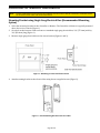
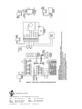
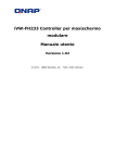
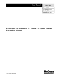
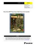
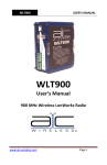
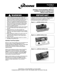
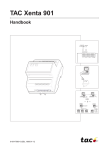
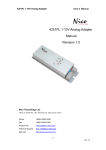
MODEL FHC50/FHM10
FUME HOOD CONTROLLER/MONITOR
P/Ns 800940/800941/800942/800950/800951/800952
INSTALLATION INSTRUCTIONS
WARNING:
The Model FHC50 Fume Hood Controller and Model FHM10 Fume Hood Monitor power input
must be wired to 24 VAC maximum. Wiring the unit to 120 or 230 VAC will cause serious
damage to the unit and void the warranty.
Download the Operation and Service Manual for the Model FHC50 Fume Hood Controller or Model FHM10
Fume Hood Monitor from our website, www.tsi.com.
The purpose of these instructions is to guide the installer through the installation of the Model FHC50 Fume
Hood Controller or Model FHM10 Fume Hood Monitor. Please read these instructions thoroughly before
beginning installation.
Included Parts
Description
FHxxx Controller or Monitor (depends on model)
Mounting Bracket
Mounting Screws (6-32 x ¼”)
Installation Instructions
Qty
1
1
2
1
Fume Hood Controller / Monitor Part Numbers
Part Number
800940
800941
800942
800950
800951
800952
Description
FHM10 Fume Hood Monitor
FHM10 Fume Hood Monitor w/BACnet®
FHM10 Fume Hood Monitor w/LonWorks®
FHC50 Fume Hood Controller
FHC50 Fume Hood Controller w/BACnet®
FHC50 Fume Hood Controller
w/LonWorks®
_____________________
TSI and TSI logo are registered trademarks of TSI Incorporated.
Modbus is a registered trademark of Modicon, Inc.
BACnet is a registered trademark of ASHRAE.
LonWorks is a registered trademark of Echelon® Corporation.
Communications
Modbus®, N2
Modbus®, N2, BACnet® MS/TP
Modbus®, N2, LonWorks®
Modbus®, N2
Modbus®, N2, BACnet® MS/TP
Modbus®, N2, LonWorks®
Controller or Monitor Installation
NOTE:
If using a Sidewall Velocity Sensor, the Sidewall Velocity Sensor and the Controller or Monitor must
be mounted on the same side of the fume hood.
Mounting Bracket using Single Gang Electrical Box (Recommended Mounting
Option)
1. Select the mounting location for the Controller or Monitor. The Controller or Monitor is typically mounted
above the service controls (Figure 1).
2. Cut a hole at this location, sized to mount to a standard single gang electrical box, 2¼” (57.2mm) wide by
3¼” (82.6mm) long (Figure 1).
3. Mount a single gang electrical box in the cutout location (Figures 1 and 2).
Figure 1: Mounting Location and Electrical Box
4. Attach mounting bracket to the electrical box using the two supplied screws (Figure 2).
Figure 2: Attach Mounting Bracket to Electrical Box
Page 2 of 6
Mounting Bracket without Electrical Box (Alternative Mounting Option)
1. Select the mounting location for the Controller or Monitor. The Controller or Monitor is typically mounted
above the service controls (Figure 1).
2. Cut a hole at this location, 2¼” (57.2mm) wide by 3¼” (82.6mm) long (Figure 1).
3. Center the mounting bracket open area on the hole. Attach the mounting bracket to the fume hood front
panel using four sheet metal screws (screws not provided) (Figure 3).
Figure 3: Attach Mounting Bracket to Fume Hood Front Panel
Attaching Controller or Monitor to Mounting Bracket
Position the top of the Controller or Monitor on the alignment tabs at the top of the bracket. Push down on the
top of the case while pressing the bottom of the Controller or Monitor into the mounting bracket until it latches
securely into place (Figure 4).
Figure 4: Attaching to the Mounting Bracket
Page 3 of 6
Removing Controller or Monitor from Mounting Bracket
Insert a flat tip screwdriver into the bottom of the Controller or Monitor as shown. Turn the screwdriver
clockwise to release the Controller or Monitor from the mounting bracket (Figure 5).
Figure 5: Removing from the Mounting Bracket
Installation Notes for Optional Accessories
800320 – Sidewall Velocity Sensor
If the 800320 Sidewall Velocity Sensor is being used, follow the instructions supplied with that equipment.
800920 - Slimline Display
If the 800920 Slimline Display Kit is being used, the Model FHC50 Fume Hood Controller or Model FHM10
Fume Hood Monitor most often will not be mounted to the fume hood front panel as described earlier in this
installation guide. If this is the case, the Controller or Monitor should be mounted on top of the fume hood, or in
any other convenient location. A good method to accomplish this is to use a standard single gang electrical box,
and mount it to the desired location. Then attach the mounting bracket to the electrical box and the Controller
or Monitor to the bracket as described earlier in this installation guide.
800925 – Vertical Sash Sensor
If the 800925 Vertical Sash Sensor is being used, follow the instructions supplied with that equipment.
800926 - Flush-Mount Bracket
The Model FHC50 Fume Hood Controller or Model FHM10 Fume Hood Monitor may alternatively be mounted
to the fume hood front panel using the 800926 Flush-Mount Bracket Kit. If using this mounting style, please
follow the mounting instructions supplied with the Flush-Mount Bracket Kit.
Page 4 of 6
Controller or Monitor Wiring
WARNING:
The Model FHC50 Fume Hood Controller and Model FHM10 Fume Hood Monitor power input
must be wired to 24 VAC maximum. Wiring the unit to 120 or 230 VAC will cause serious
damage to the unit and void the warranty. Alternatively, if using an Electric Actuator, the
Actuator DC power output may power the Controller or Monitor power input (15-40 VDC).
Do not connect 24 VAC to any terminals other than the Controller or Monitor power input.
Maintain polarity on all wiring connections.
The Controller or Monitor must be wired exactly as the wiring diagram shows. Making
modifications to the wiring may severely damage the unit.
Do not apply external voltage to the RS485 ports, Analog Output, or Control Output. These are
output voltage signals.
Make sure no power is applied until all wiring is complete. Follow all applicable electrical codes,
and have a qualified person perform all wiring.
1. Remove the connector blocks from the back of the Controller or Monitor.
2. Refer to the wiring diagram (Figure 6) for proper wiring procedures, and connect all necessary wiring to
the connector blocks.
3. Plug in any cable connections for optional accessories (Velocity Sensor or Slimline Display) to the back of
the Controller or Monitor.
4. Plug the wired connector blocks into the Controller or Monitor in the appropriate positions.
5. Attach the Controller or Monitor to the mounting bracket.
Page 5 of 6
Figure 6: Controller or Monitor Wiring Diagram
TSI Incorporated – Visit our website www.tsi.com for more information.
USA
UK
France
Germany
Tel: +1 800 874 2811
Tel: +44 149 4 459200
Tel: +33 491 11 87 64
Tel: +49 241 523030
P/N 6003881 Rev. C
India
China
Singapore
©2013 TSI Incorporated
Tel: +91 80 67877200
Tel: +86 10 8251 6588
Tel: +65 6595 6388
Printed in U.S.A.