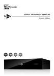
1
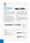
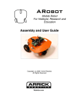
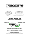
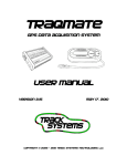
PDR100 User Manual 5-11-2007 Consumer version
PDR 100
User Manual
Thank you for purchasing the ChaseCAM Solid State Digital Recorder!
CAUTION!!!
Read this User Manual. There are no user serviceable parts inside. Removing the endplate
screws will void your warranty. If your PDR requires servicing, please contact the factory. Do not
use the PDR to power other devices other than a single bullet camera.
This document is a work in progress and reflects only the version of the PDR100 that was
shipping at the time it was printed. Please stay current by checking the chasecam.com forums
and downloads. We are continually adding features to your PDR.
http://www.chasecam.com/
619 337-2300
Contents of Package (not including options)
The PDR 100 ships with the following items:
PDR100
User Manual
The following items are optional and may be included in a kit or ordered directly from a dealer or
Chasecam:
MiniAV Adapter Cable (3.1mm to three RCA jacks)
Line In Audio Adapter (3.5mm to dual RCA jacks)
Compact Flash Card (various sizes)
Cigarette Lighter Adapter (2.1mm DC jack)
Hard Wire Adapter
External Battery Pack
MiniDIN to RCA/DC Adapter Cable (connects to RCA and 2.1mm DC jack)
Four Lithium AA Batteries
USB Compact Flash Card Reader
LCD Viewing Screen
Mounting Brackets
Protective Fabric Case
Personal Harness
Weatherproof Box
Gforce module
QUICK SET UP GUIDE
Unpack the PDR100 and make sure you have everything you need.
Open the front access door by turning the thumbscrew counterclockwise.
OPTIONAL- Open the door far enough down, and insert four batteries into the PDR100.
Note the direction of the batteries printed on the printed circuit board.
Insert a Compact Flash card into the slot above the batteries. Note that the CF Card can
only be inserted one way (flipped over, so that the “top” of the card is facing the
batteries). The CF Card must be fast enough for video. Make sure that the card is fully
inserted.
Close the door with one hand and align the thumbscrew into the captive nut. Tighten the
thumbscrew.
If you are not running off of the batteries, connect the PDR100 to a power source that
supplies 12Volts DC. We recommend conserving battery life by using other power
sources when available. Use either the supplied cigarette lighter adapter, or you can
hardwire to the pluggable terminal block on the back of the unit. Take care to use the
input pins. Do not use the output power of the PDR to power any other devices!
Connect the video input or camera device using the MiniDIN connector or a supplied
ChaseCam adapter cable (allows direct RCA plug in). Do not plug in any other
connectors, even if they fit! This is not an S-Video connection.
If you would like to see the video or aim a camera, connect an external LCD or other
video device to the PDR using the industry standard MiniAV Adapter Cable.
Press the Power/Record button (on PDR or remote). The LCD will light up.
After a few seconds delay, the LCD will be displaying text, first displaying the PDR
software version and then showing you a status screen.
If there are any error conditions noted on the LCD, please correct them (no CF card, no
video, low battery).
Using the menu on the keypad, you can adjust the video screen resolution, video quality,
sound levels, and much more. Press X or MENU to back out of the menu until the LED is
solid green.
Press the Power/Record button to start recording.
Note the file name of the recording that is now being displayed on the LCD.
Press the Power/Record button again to stop recording.
At the status menu screen on the LCD, hold the Power/Record button down for two
seconds to power the unit off.
You can play the videos directly from the PDR using the MiniAV adapter cable, or you
can remove the Compact Flash card and using a USB card reader, transfer the files to
your computer.
LED STATUS. Solid green = ready to record. Flashing green = error or check message
on LCD. Flashing red/green = recording. Slow flashing red = not ready, in menu mod3.
Detailed Operation
Safety and Warnings
The PDR100 has no user serviceable parts inside. Please do not open the unit by
removing the end plates. Doing so can damage the unit and void your warranty.
Operating temperature range is 0 degrees F to 110 degrees F. The unit will get warm,
this is normal. Do not fully enclose the unit on a hot day.
Restrict input voltage to a range from 9V to 18V DC. Never apply AC voltage to the PDR.
Restrict powering other devices from the PDR output power to 300ma. You can power a
ChaseCam external LCD and a camera. Do not operate the SS1000 or another PDR
from the PDR power output. You can operate a PDR from the SS1000’s power output.
Unit is not waterproof. Should the PDR100 become wet, remove the Compact Flash card
and any power and/or batteries and attempt to let the unit air dry with the access door
open. If the fails to operate, contact the factory for repair.
Do not leave batteries inside the unit for long periods of time. Periodically check batteries
inside the unit.
Care must be taken when using the PDR100 while in operation of any moving vehicle or
while being involved in any moving sport. The user-selectable adjustments are designed
to be operated while a vehicle is parked. Do not do anything that will place yourself in
danger or distract you from the safe operation of a vehicle.
Description and Overview
The PDR100 is an audio/video recorder that writes digital audio/video files to a Compact Flash
card. The unit accepts external audio and video, microphone, and alternately has an internal
microphone. The PDR100 can be operated with a wired remote control and includes a flexible
digital interface.
Controls and Connectors
The Keypad and LCD surface are used for control and setup of the PDR and to provide valuable
data back to the user. Keypads should provide an audible click when pressed and successfully
activated. Care should be taken to not scratch or harm the keypad and LCD.
The front panel of the PDR has one switch and one red/green LED indicator. The switch
performs multiple functions. It powers the PDR on and off, and starts and stops recording also.
The LED informs the user if the PDR is recording, ready, on or off, or displaying an error
condition. The front panel also includes an access door for the batteries and the Compact Flash
connector.
The rear panel has the connectors for the PDR.
MiniDIN connector for Video Input (and 12VDC Power Output) NOT S-VIDEO!
Microphone Input
External Audio Input using a 3.5mm to stereo Audio Adapter
LAN-C connector for use with a LAN-C device such as a remote control
Digital Interface RJ-45 connector for use with ChaseCam remotes and other items that
use the RS-232 interface such as Data Acqusition
Audio/Video Output via a 3.5mm MiniAV jack
DC Power Input Jack (2.1mm DC jack, center positive)
DC input and output terminal block
LED Indicator Table
No Light = Unit is not powered
Green, Steady = Unit is on (Standby Mode) and ready to record
Green, Flashing Slowly = In Standby but not ready to record or low battery. Door could
be open, no card, card is full, no video present, low battery.
Green, Flashing Rapidly. Playing back recordings. The higher the quality, the faster the
flashing.
Red, Flashing Slowly = Recording but battery is low or other warning condition (see
LCD screen), or not in Standby Mode since user has the menu somewhere other than
Recording Standby.
Red and with Green Flashes = Recording Video. Flash frequency indicates quality of
video.
Video and Audio Connections
Video. If you are using the PDR with a ChaseCam camera, simply plug the camera’s MiniDIN
cable (or extension cable) into the PDR Video Connector. If you are using some other camera,
you will connect the camera to the MiniDIN adapter cable using the RCA and DC jacks. If you
are recording from another video source such as a TV or DVD player, you will also use the
MiniDIN adapter to connect to the yellow RCA jack.
External Audio. If you are recording external audio (such as a TV or DVD player, or other
electronic device that has sound coming out on an RCA jack, connect the audio to the RED
(Right) and White (Left) using a ChaseCam Audio Input Adapter (optional) and plug that cable
into the External Audio Connector. You can also use a standard 3.5mm Stereo or Mono adapter
to connect to a CD/DVD player or other device.
Microphones. You can connect a standard non-powered electret microphone to the Microphone
Input jack. Select the proper setting for audio input in the SETTINGS menu. Technical note. We
have placed the negative on the sleeve of the phone plug, and the left and right positive on the tip
and ring. Plugging in a single electret mike on a mono phone plug produces audio only on the left
channel. A single electret mike with its positive side connected to both the tip and ring of a stereo
plug produces mono audio in both channels.
Internal Microphone. The PDR includes an internal microphone designed to pick up ambient
sounds and record those sounds on both left and right channels. If you do not plug in anything
into the External Audio or Microphone, the PDR will use the internal microphone.
Menus and Set Up and Use
Powering On and Recording Standby Mode/Recording
The opening screen on the LCD, when powering up the PDR, will briefly display the PDR
software version, along with the date of the software version. Then the PDR goes into automatic
Recording Standby mode. The LCD screen will be backlit for a period of 30 seconds.
Recording Standby. The LCD screen will show the date and time at the top. Below that is an
active audio input meter, which is shown as a bar graph. An asterisk at the end of the audio bar
graph will indicate that the sound is being clipped. Video status will be shown as “NO INPUT” or
“READY.” The Compact Flash status will be displayed as “NOT IN”, “FULL, or “READY.”
The audio output is enabled in this condition and you can use headphones to listen to the audio.
Headphone sound levels can be adjusted with the UP and DOWN keys on the keypad. If you are
using the LINE OUT Audio, then adjust the volume to the maximum.
In Recording Standby mode, pressing and holding the Power/Record key (or remote button)
continuously for two seconds will turn off the PDR.
Recording. Pressing the Power/Record key (or remote button) will start and stop recording. When
recording, the LCD backlight is turned off, video output is turned off, audio output is turned off.
The LCD screen will show “RECORDING….” And a line identifying the file path and name will be
displayed. If the unit is not ready to record, the LCD backlight will flash and the LCD will display
“NOT READY TO RECORD” and return to Recording Standby mode.
NOTE: If an attempt was previously made to record to a CF Card that was not fast enough, there
will be an error message displayed "FLASH MEDIA WAS TOO SLOW!" after the recording is
stopped. The recording is made, but it will contain skips and may cause errors in player software.
There will be a number to indicate (0-10) the severity of the problem.
Recording will end when the CF Card is full, power in the batteries drops too low (the PDR will
also turn off), the access door is opened, the maximum size of 4 gigabytes is reached (per file), or
the Power/Record (or remote) button is pushed.
Saved Settings
The PDR will store the settings as programmed by the user if when not powered. You will not
need to enter in the settings more than once unless you want to change the settings.
Top Menu
At the Recording Standby Mode, press the MENU key on the keypad. You will see four options.
RECORDINGS LIST, CONTROLS, and SETUP. Press MENU or ESCAPE (X) to return to the
Recording Standby Mode. Pressing the UP and DOWN keys will move between and highlight
selections. Pressing the center SELECT or ENTER key will bring up a new menu related to your
selection.
When in these MENUS, the LED Indicator will slowly flash RED to indicate that the unit is not
ready to record. Also, video and audio outputs will be disabled.
Recordings List and Playing Video
Selecting RECORDINGS LIST from the TOP menu is used to view details about the
recordings stored on the Compact Flash card, to play them on the A/V output, or to remove
recordings from the Compact Flash.
If this selection is made when no Compact Flash card is inserted, a message appears on the LCD
saying "Compact Flash not in". If there are no recordings on the card, the message "No
Recordings" appears.
If there are recordings on the card, the first one available appears with details about it on the
screen. Pressing the UP and DOWN keys brings up details about other recordings, moving
through the list of all available. The top line displays RECORDING N / N, where the first number
in place of N states the position in the list the screen is currently showing, and the second
number says how many recordings there are on the card.
The screen shows the directory path and file name of the recording. The third letter of the file
name indicates, by either N or P, whether the recording is NTSC or PAL.
Below the file name is shown the size of the file in megabytes. Below that are shown the date and
time (only accurate to two seconds, the resolution of the file system time stamps) of when the
recording was started and when it was ended.
On the bottom line of the LCD, above the function keys, are labels for actions which can be taken
on the currently displayed recording. Over the THREE key is "Delete". Pressing the THREE key
is used to remove the recording from the Compact Flash card. When the key for Delete is
pressed, the screen will change to ask the question "DELETE RECORDING?". To complete the
removal process, the TWO key must be pressed, which has "Confirm" displayed above it on the
LCD. When the Confirm screen is up, pressing the ESCAPE key returns the recording view to
normal without removing the recording. Pressing the MENU key returns to the Recording Standby
condition without removing the recording.
While viewing the recordings list, pressing the MENU key returns to the Recording Standby
condition. Pressing ESCAPE returns to the TOP menu.
When viewing a recording in the list, over the ONE key is "Play". Pressing the key for Play starts
playback of the selected recording. The video output and the headphones are turned on for
playback. During playback, the SELECT key can be pressed to pause playback. Pause takes a
second or two to take effect. The playback can be continued by pressing SELECT again. The top
of the LCD will display either PLAYING or PAUSED during playback.
During playback of videos, you will see an indicator at the top that is moving. Pressing the left or
right cursor keys will rewind or fast-forward the video by 3X, 15X, or 60X speed. If you pressed
the right direction key and the video is not fast-forwarding by 3X, pressing the left direction key
will put the unit back into normal play mode.
When the end of the recording is reached, the video and audio outputs will turn off, and the
normal recording list view of the recording returns. During playback when the recording is not
paused, the headphone volume can be adjusted with the UP and DOWN keys.
To stop playback before the end of the recording, playback must be paused by pressing the
SELECT key. When playback is paused, pressing the MENU key returns to the Recording
Standby condition. Pressing ESCAPE returns to the recordings List view.
CONTROLS MENU
The items in the CONTROLS menu are RECORDING QUALITY and AUDIO INPUT LEVEL.
Pressing MENU returns to the Recording Standby condition. Pressing ESCAPE returns to the
TOP menu (previous menu).
Pressing the UP or DOWN keys moves the highlighted selection between the choices. Pressing
the SELECT key moves to a new menu pertaining to the selection.
RECORDING QUALITY
When the RECORDING QUALITY screen is up, the selection of the MPEG video recording bit
rate can be made. Higher bit rates correspond to higher recording quality. Pressing the UP or
DOWN keys moves the highlighted selection between the choices. Pressing the SELECT key
makes the selection and returns to the CONTROLS menu. Pressing MENU returns to the
Recording Standby condition without changing the recording quality, and pressing ESCAPE
returns to the CONTROLS menu without changing the recording quality.
The seven choices for bit rate are:
HIGHEST 8.0 megabits per second
HIGHER 6.0 Mbits/sec
NORMAL 4.0 Mbits/sec (Default)
SUBNORMAL 3.0 Mbits/sec
LOWER 2.2 Mbits/sec
LOWEST 1.5 Mbits/sec
Bit rates shown are for FULL SCREEN VIDEO. Smaller screen resolutions will use a lower
bitrate.
VIDEO RESOLUTION
The resolution menu will allow you to select a different screen size than the default. You might try
experimenting with resolutions and bit rates to determine the proper setting you need. There are
three choices.
FULL VIDEO (740x480 NTSC or 720x576 PAL) –default2/3 HORIZONTAL VIDEO (480x480 NTSC or 480x576 PAL) SVCD size
¼ SCREEN VIDEO (352x240 NTSC or 352x288 PAL) VCD size - MPEG1
AUDIO INPUT LEVEL
When the AUDIO INPUT LEVEL screen is up, the selection of the input audio level can be made.
Pressing the UP or DOWN keys moves the highlighted selection between the choices. Pressing
the SELECT key makes the selection and returns to the CONTROLS menu. Pressing MENU
returns to the Recording Standby Mode condition without changing the audio input level, and
pressing ESCAPE returns to the CONTROLS menu without changing the audio input level.
There are four preset INPUT LEVEL selections, which are usually best for the kind of input the
selection describes:
LINE IN (for using the external audio line-in connector)
STEREO MIC CLOSE UP (for two electret microphones of sensitivity similar to that of the
on-board microphone, plugged into the external microphone jack)
PDR100 MIC CLOSE UP (for a speaking voice nearby the PDR100's microphone)
MIC WIDE AREA (for the PDR on-board microphone to pick up room or other area
sounds).
There is also a selection labeled OTHER. This allows the user a choice of input level other than
the presets. A bar graph shows the relative amplification, which is selected by using the LEFT
and RIGHT keys. When one of the presets is highlighted, the bar graph corresponds to the level
for the preset. For a loud racing car (for an example), select OTHER and slide the bar graph to
the left.
When the AUDIO INPUT screen is up, the headphone volume is set at the level previously
adjusted in Recording Standby or playback of a recording so that the effect of the input
adjustment can be monitored.
Microphone Level
Set this to HIGH or LOW depending on the level of sound. Suggestion is to set it to LOW for use
inside of a racecar.
LOOPING
Set looping to ON or OFF. Video Looping allows a continuous recording of the video. You can
also in this menu area, allocate a certain file size for the LOOP file. This means you can
determine a certain amount of time that is recorded. Use the right and left direction keys to
increase or decrease the loop file size.
SETUP MENU
SET DATE AND TIME
When the SET DATE AND TIME screen is up, one field is highlighted for adjustment, and the
LEFT and RIGHT keys are used to change the selection to another field. Year, month, day, hour,
minute, and second are displayed. When the UP or DOWN keys are pressed, the highlighted
selection is adjusted up or down.
Pressing MENU sets the date and time according to the current display on the LCD, and returns
to the Recording Standby condition. Pressing ESCAPE returns to the SETUP menu (previous
menu), without changing the date and time.
SET FILENAMES
You can change the default first two characters of the saved files to whatever combination of
letter/number characters you choose. The default is CH. Change the characters by using the
directional up and down keys and use ENTER to set. This is useful for multiple recorders so you
can know which files came from which recorder.
On the right hand side of the screen, you can see NEXT ON CARD. This setting means that the
PDR will start with the next file number. This means that if you insert a blank card, the first file will
be CH_0001.MPG. If the card has files on it, the PDR will start with the next higher incremental
number. The downside of this method is that you might have multiple files with the same number.
Pressing select on this will toggle the condition to SAVED IN PDR. This means that the PDR will
create a new incremental filename and store that number in the PDR. So if you have done 99
recordings, the next file will be CH_0100.MPG. This is useful if you do multiple files and want
them to always be a unique filename.
SET DISPLAY CONTRAST
When the DISPLAY CONTRAST screen is up, you may press the LEFT and RIGHT keys to
change the LCD’s text screen contrast. Press Menu to save your settings.
SET SERIAL NUMBER
If your PDR is not factory preset, you can enter in the actual serial number here. Use the
directional keys to change the settings and enter to save. Do not guess at a serial number, it will
not work! Serial numbers have to be supplied from the factory. If a serial number has already
been set, this menu selection will display the set serial number. Once a number has been
assigned and set, it can’t be changed. The serial number is used for specific software features.
ON SCREEN DISPLAYS
The menu options here will depend on the options that are built into the PDR. If your PDR has the
MoTeC interface, you will be offered the MoTeC menu. If your unit has the GForce option, then
you will see the GForce menu. All units will have the TIME DISPLAY menu.
PRIORITY OF DISPLAY
Turning on GFORCE DISPLAY will override the TIME DISPLAY. If TIME DISPLAY is on, then
turning off the GFORCE DISPLAY will allow TIME DISPLAY to function. You can not at this time
have both GFORCE and TIME displaying.
TIME DISPLAYS
You have four different ways of displaying time as text recorded directly on the video. The first
menu section will toggle through the options. You can show DATE + TIME on the video, show
only the actual TIME, or show elapsed RECORDING TIME. Recording time is useful as a track
timer.
TURN ON DISPLAY – TURN OFF DISPLAY
Pressing key 2 will toggle the timer displays on and off from being recorded on the video.
CLEAR BACKGROUND – SHOW BLACK BACKGROUND
This will put white text directly on the video. Less obtrusive, but might not work as well if the
background is very light. You may get better results in that case, by toggling this to SHOW
BLACK BACKGROUND which will place the white text on a black bars.
PUT AT TOP – PUT AT BOTTOM
Moves the text and bars to either the top or bottom of the screen.
GFORCE
The GF module is available as an option from your dealer or ChaseCam. The module is sold as
either an internal or external device. The internal module needs to be factory installed. If your unit
does not have the GForce module, you will not see the menu option. The GForce module will
overlay the GForce readings and scaled moving bar graphs onto the video, in real time.
Technical data- The GForce module is 3 axis and user set. This means that you can place the
module or recorder in any orientation. The GForce is sampled once per video frame, or 30 times
a second for NTSC and 25 times a second for PAL. The horizontal bar graph is scalable (up to
3G). Vertical bar graph is red for braking (negative G), and green for acceleration (positive G).
CLEAR BACKGROUND – SHOW BLACK BACKGROUND
This will put the text and bars directly on the video. Less obtrusive, but might not work as well if
the background is very light. You may get better results in that case, by toggling this to SHOW
BLACK BACKGROUND which will place the text and GF bars on a black background.
PUT AT TOP – PUT AT BOTTOM
Moves the horizontal text and bars to either the top or bottom of the screen. The left side vertical
bar is not movable.
TURN GFORCE TEXT ON - OFF
This setting allows you to turn off the text that displays the GF readings (such as 1.04) and only
display the bar graphs.
SCALE
You can set the scale to match the vehicle. The most common setting for most race cars would
be 2. We recommend using 1 for street use. A setting of 3 would be used for more extreme racing
cars or vehicles. If the GF readings exceed the scale, it will just mean that the bar graph will be at
the end of what it can display. The text will still reflect the actual measurements (up to 4G).
SET ORIENTATION
This will allow you to calibrate the GF module. Very simply, with the module or recorder securely
in the position you intend to use it, position the vehicle on a level surface with enough room to
complete the calibration. Press SELECT when parked. Wait one second and then accelerate
straight forward for a short distance and then fully brake to a complete stop. You do not need to
use excessive speed or braking forces. You are only instructing the module to learn where it is
located relative to directions. Press SELECT again. The PDR LCD will display if it was successful
or not. Press SELECT again to see a report screen.
RESET ORIENTATION
This simply resets the orientation to the factory preset. The preset for an internal GF module is
assumed that the PDR is flat with the LCD/Keypad facing upwards and the button/led/battery
door is facing the rear of the vehicle.
Batteries and Power Sources
The PDR uses four AA sized batteries for internal power and can use an external power source
(battery pack, vehicle power, etc) that is plugged into the PDR using either the DC jack, or the
Terminal Block. It is recommended that if you are using external power, that you also install the
internal batteries as a back up for any possible power loss.
Battery types. We recommend using Energizer AA Lithium, Duracell Ultra (not regular
Duracells), or good rechargeable NiMH (Nickel Metal Hydride) batteries. You can use standard
alkaline AA batteries to power the PDR for short periods of time, or as a power back up, but if you
are powering an external camera from the PDR, alkaline batteries will only enable about 3
minutes of usable power to the PDR. As a comparison, the Energizer Lithium batteries will enable
over 2 hours of continuous use. Good (2500mah or better) NiMH rechargeable batteries should
last over 2 hours.
Installing the batteries. Open the access door by turning the thumbscrew counterclockwise.
When free, swing the door down to where it contacts the rubber bezel. Note the orientation of the
batteries that is printed on the circuit board and take care to insert each battery in the correct
direction! Insert each battery into the housing. Close the access door while guiding the
thumbscrew into the captive nut. Tighten the thumbscrew by hand.
External power connections. You can use various methods to connect external power to the
PDR. A cigarette lighter adapter with a DC jack is a common method. You can also use insulated
wires and connect to the power input pins on the green terminal block. This terminal block is
removable and also able to be locked in place with a small flat bladed screwdriver. You also can
use the power output pins on the terminal block to provide power to other 12VDC devices that
draw 300ma or less. It is intended to be used for powering a bullet camera, not other higher
current devices. DO NOT POWER ANOTHER PDR OR SS1000 from the output.
External Battery Packs. You can connect an external battery pack to the PDR. Using an eight
AA cell pack will allow you to use standard alkaline batteries and run a PDR and camera from the
eight batteries for approximately 3 hours. ChaseCam offers external battery packs.
Low Battery Warning. If you are running off of batteries and the PDR senses a low voltage
condition, the LED indicator will change to a red flash and the LCD screen will note that a low
battery condition exists. If the voltage drops below a certain point, the PDR will stop recording,
save the file, and shut down. Bullet cameras will also exhibit certain behavior under low voltage,
such as wavy lines, colored lines, loss of color.
Removal of External Power when Recording. If you are not using internal batteries for back up
and you disconnect the power while recording, you can lose the recorded file and can potentially
corrupt the entire Compact Flash Card. Be careful to not lose power and we do recommend using
batteries for back up. If you lose power while recording, your file size may not accurately display.
If power fails during recording, we recommend inserting the Compact Flash Card into the reader
and using Windows Command Line and type “chkdsk /f <drive letter>:” where the drive letter is
the letter assigned to the card reader by the PC. Do not type the quotation marks.
Compact Flash Cards
The PDR should accept any industry standard Type I or Type II Compact Flash Card. We are
testing various cards and if we find any that are compatible, they will be listed on our web site.
Cards larger than 4gigs must be formatted with FAT32. The PDR can write to FAT16 or FAT32
formats. Simply right click on the CF card/reader location on your computer and select “Format”.
Speed. The user will need to match the card to the intended “video quality” bit rate, or match the
“video quality” bit rate to the speed of the CF card that is installed. CF Cards are defined by some
manufacturers with these numbers as a rough guide:
24X is 3.6Mbits/SEC
40X is 6Mbits/SEC (Normal Video Quality)
60X is 9Mbits/SEC (Highest Video Quality)
Note that excessive file fragmentation, space available, and manufacturing differences may affect
your actual speed. Some cards from certain manufacturers allow a faster speed than others,
regardless of what the number that is listed. We highly recommend careful choice of cards and to
allow some extra speed “capacity” when selecting your card.
If your card does not allow higher speeds that you have selected in the menu, the LCD will note
that CARD WAS SLOW! Your resulting video will be jumpy and have skips and you may have
audio drop outs. The number following the “CARD WAS SLOW” message indicates how severe
the problem was, on a scale of 1-10. This will tend to be worse at higher video quality settings,
on larger cards, as the card gets more full, and as the card’s file system gets more fragmented.
You can try a fresh format, reducing the video quality setting, using less of the card’s capacity as
ways to test and solve this.
Capacity. Normal Video Quality at Full Resolution setting (4Mbits/Sec) will take up around 30
minutes per gigabyte. The rest is mainly math. Half the resolution will take half the space. Double
the quality will take twice the space.
File Transfer and Video Editing
To transfer files from the Compact Flash card to a PC, remove the card from the PDR and insert
the card into a CF Card reader. It is recommend that files be copied to a PC for playing and
editing. Copying a large video file from a CF Card to a PC can take some number of minutes
depending on your type of connection such as USB and your system. A newer computer should
be able to transfer the files rapidly. We find we can transfer files at a rate of 1 gigabyte per minute
on the average using USB 2.0. On an older PC, this can increase to 10 minutes per gigabyte. We
do not recommend the use of PCMCIA adapter cards as they are normally slower.
Video Playing on a PC. The video files from the PDR are MPEG-2 format, which use a standard
DVD Decoder to play. Your version of Windows Media Player or some other player you are using,
may not know how to properly handle MPEG-2 files. If you get an error message or a message
saying you are missing a CODEC, this means you should download and install a CODEC, or use
an alternate player. See the chasecam.com website for more information and downloads. We do
recommend the free software available from videolan.org. This player is called VLC and works on
most computer platforms.
Video Editing recommendations. ChaseCam recommends the use of Adobe’s Premiere
Elements. This is a good value program (under $100 retail) that has most of the features that a
user would typically need and is relatively easy to use.
Creating DVDs using your PDR files. In Windows, you can simply drag and drop the video files to
a DVD writer.
Updating PDR Software
The PDR is easily field upgradeable. This means you can easily download an updated software
system and load it to your Compact Flash card, install the card in your PDR. Close the door and
then boot up the PDR while holding down the MENU key on the keypad. Continue to hold down
the menu key for three seconds. When you see a steady text display showing the UPDATER
software, release the menu key. This will then show you some text on the LCD that it is updating
the software. If the update is successful, the UPDATER will turn off the PDR. When the PDR first
boots up, it will display the version of the software that is loaded in it.
To see the current version of software available to the user, please visit
http://www.chasecam.com/forum/ and visit the PDR100 Digital Video Recorder FAQs, or you can
just download the latest version from http://www.chasecam.com/sw/pdr/update.bin
Using the optional mounting bracket
To mount the PDR securely to a hard surface, place the Mounting Bracket Base to in the location.
Please note orientation of the PDR when installed, for wiring access and also location of the
switch and LED. There are six pre-dilled holes with countersinks on the inside bottom of the
bracket, these are designed for number 6 screws. Do not use any other type of screws except for
flathead in order to clear the bottom of the PDR module. These screws are in a pattern that is two
rows that are spaced 1.00-1.25” apart (check which version!), with the holes spaced 1.50” from
the center. Alternately, you can use up to ¼” screws on the outer ears to bolt down the bracket.
These ¼” slots are 1.00-1.25” apart also, and spaced at 5.45” from center to center. Later
brackets use the 1.00 spacing. Earlier brackets were 1.25”. Brackets can also be mounted to our
SM30 suction cup base for easy mounting in cars.
Once the bracket is securely attached, insertion of the PDR is very simple. Just center the PDR
over the bracket and with a slight angle towards one side, push the PDR down. You should hear
an audible click as it snaps into place. To remove, just push one side of the mount away from the
PDR and pull up on the PDR to release. Many repeated installations and removals might loosen
up the snap. In that case, simply push the side of the metal (with the PDR not installed) towards
the middle to reset the tension.
For an even more permanently secure method, install the retaining cover over the PDR. Align the
edges onto the rubber of the PDR and over the handles of the mounting bracket. Using the
supplied pin, lock the retainer to the bracket. You will still have access to the LCD screen and
keypad.
TROUBLESHOOTING (common tests and/or solutions):
NOTE- In many cases, there are some simple things to check and test. A problem can be
solved by upgrading to a newer version of the operating system firmware, so check to see if you
have the latest version. In no case is the unit able to be repaired internally outside the factory or
authorized repair facility. Removing the endplate screws will void your warranty. Trust us on this,
most people will damage the unit internally when they try to open it up, and we will know. Please
let us fix things. Fuses are not field resettable or fixable.
POWER and CONNECTION ISSUESUnit will not power up off batteries. LCD is blank and does not light up. LED on front panel does not light
up. Check to make sure you are getting sufficient power. Try a fresh set or freshly charged set of batteries.
Check the screws on the endplates on both ends and make sure they are tight. The batteries require all
parts to be fully seated and fastened to make a good connection. Check the battery door to make sure it is
securely attached at the hinge. Try pushing on the door and seeing if pressure applied allows the batteries
to function. Try powering the PDR from vehicle power. If the battery door needs repair, or if it still fails to
work, then call for a repair.
Unit will not power up off external power. LCD is blank and does not light up. LED on front panel does
not light up. Try running the unit off batteries. Check power cabling. If you have a voltmeter, see if you are
getting 12V on the power input. Some cigarette lighter adapters and sockets are fused and may fail. If the
unit still fails to turn on, call for a repair.
White Screen of Death. Unit powers up, but no text on the LCD. LED is blinking. Make sure you are getting
enough voltage when using external power or internal batteries. Not enough voltage can cause this.
Otherwise call for a repair.
Unit powered off after a few minutes and now will not power up. Make sure you are not powering up
more than a bullet camera from the power output. Doing so will cause an internal fuse to blow. Check your
power source also. This requires a factory repair.
No video present. Make sure the camera is functional by viewing the video on another monitor if possible.
Certain cameras do not work well with the PDR100 and may fail to register as “video” to the PDR. Try using
an alternate video source to the PDR if possible. If you are using a ChaseCam camera, after being
plugged in for some minutes, is it warm to the touch? If you have a voltmeter, check for +12V output on the
camera connector from the PDR. A lack of power from the PDR indicates a blown internal fuse and requires
factory repair.
Need a more secure power connection than the DC jack. Use the plug in terminal block. Or upgrade to a
–R unit.
My camera has an RCA or BNC jack. You need the ChaseCam adapter cable, or upgrade to one of our
cameras.
COMPACT FLASHCompact Flash Not In. This can happen with certain cards. And occasionally a Compact Flash card will
become damaged. Make sure that there is no debris on the CF card connector. Try another brand of card.
Do not use micro-drive cards. Make sure the CF card is not badly corrupted, can your computer see it and
reformat it?
Compact Flash Door Open. UPGRADE YOUR FIRMWARE!
Compact Flash Too Slow. Video was choppy. Audio dropouts. Try reformatting the CF card. Try using a
faster CF card. Try running at a lower video quality setting. Use smaller cards. Use less of the card (the end
gets slower as the card gets full).
VIDEOWavy lines in the video. Check to make sure you have sufficient power. If the unit is connected to other
units, try not to create ground loops. Keep the video and power lines away from ignition systems. Try moving
the video cable. One fix may be running it off batteries (internal or external).
Horizontal lines in the video when viewing on a computer. This includes “tearing” and strange color
shifts. Or if you can’t see the video and only get the audio. Get the right CODEC or use VLC from
videolan.org to play the files. Loading a DVD player software in Windows should also load a proper CODEC.
Blury Video. Check to make sure you do not still have the “peel off” label on the lens. Is the camera
focused? Can you check the video on some other device? ChaseCam can refocus cameras we sell, or we
can offer instruction for the person who wants to attempt this.
SOUNDToo much noise, wind noise. Relocate the unit out of the windstream. Program the audio to use the LOW
setting on the microphone, and/or adjust the gain in the menu. If no matter what, the sound is over
modulated, return the unit to ChaseCam for a factory adjustment. Or use an external microphone.
Ignition noise. Relocate the power. Make sure the power/video lines are not near the ignition.
OTHERMy keypad does not work. Unit needs simple repair by ChaseCam.
LAN-C no longer works. Unit needs simple repair by ChaseCam.
Battery door captive screw washer came off. Easily threads back on. Call us for a new washer if you lost
it.
Files are too big. Try using a smaller video size in setup, especially if the intent is to upload the video to
sharing sites like YOUTUBE. Also do real time editing. In other words, press record when you want to record
and stop when you are done. It is very common for people to record a lot of extra time before and after the
real video they wanted.
I need to be able to record longer. Get a larger card or reduce the video size and/or quality. With a 16 gig
card, you can get 100+ hours of video at low res settings. Also, you can swap cards.
Specifications
Size: 3.5” x 4.5” x 1.75”
Enclosure: Extruded and anodized aluminum with anodized aluminum sheet metal end plates. All
hardware is stainless steel.
Construction. Predominantly surface mounted and lead free construction printed circuit boards
Weight: 14 ounces without batteries
Operating Temperature:
Input voltage range: 9 to 18 volts
Power consumption: 500-650 ma (1/2 amp) with camera being powered. 350ma without camera.
Internal Batteries: Replaceable AA (x4)
Resources and Accessories
ChaseCam and our partner companies intend on developing various accessories to enhance the
PDR. Please check back at our website, or sign up for our ChaseCam mailing list, to be made
aware when new items are released to the market.
Resources. On the ChaseCam website, you will find links to resources, a customer discussion
area, and much more. Please visit!
Warranty
All ChaseCam products are covered by our standard 30 day satisfaction guarantee. If you wish to
return a product and receive a refund for the product cost (not including shipping), please call us
first to get a return authorization and then ship the unit back, insured shipping only. Lost
shipments are not our responsibility. Please pack the unit with care.
Additionally, the PDR100 is covered by a six month warranty that the product will be free from
manufacturing defects. If the unit fails to record in the six month period from when the unit was
shipped to you, we will fix or replace the unit with a working PDR.
As always, ChaseCam attempts to have a very user-friendly upgrade policy.
You may be covered by other laws or warrantees, depending upon your local and/or state laws.
Service
Contact us before sending anything back! We require an RMA number and filled out form. Please
download the form at http://www.chasecam.com/RMA.pdf
US RepairsChaseCam
8348 Center Drive Ste A
La Mesa CA 91942
http://www.chasecam.com/
619 337-2300