1
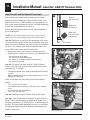
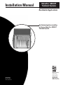
Installation Manual
AdvanTex AX20-RT
Treatment Systems
®
Residential Applications
An illustrated guide to installing
an Orenco AdvanTex AX20-RT
Treatment System.
®
Orenco Systems®
Incorporated
Changing the Way the
World Does Wastewater®
NIM-ATX-AXRT-1
Rev. 1.2, © 11/10
Orenco Systems , Inc.
®
800-348-9843
541-459-4449
www.orenco.com
www.vericomm.net
Installation Manual: AdvanTex
1
®
AX20-RT Treatment Units
Before
Begin . . . . . . . . . . . . . . . . . . . . . . . . . . . . . . . . . . . . . . . . . . . . . . . . . . . . . . . . . . . . . Page 1
Table You
of Contents
Overview . . . . . . . . . . . . . . . . . . . . . . . . . . . . . . . . . . . . . . . . . . . . . . . . . . . . . . . . . . . . . . . . . . . . . Page 3
Installation Steps
Step 1:
Review or Sketch Site Plans . . . . . . . . . . . . . . . . . . . . . . . . . . . . . . . . . . . . . . . . . . . . . Page 4
Step 2:
Excavate and Set Septic Tank. . . . . . . . . . . . . . . . . . . . . . . . . . . . . . . . . . . . . . . . . . . . . Page 5
Step 3:
Install Risers and Water Test Septic Tank . . . . . . . . . . . . . . . . . . . . . . . . . . . . . . . . . . . Page 5
Step 4:
Install Effluent Filter . . . . . . . . . . . . . . . . . . . . . . . . . . . . . . . . . . . . . . . . . . . . . . . . . . . . Page 6
Step 5:
Excavate and Set AX20-RT Unit . . . . . . . . . . . . . . . . . . . . . . . . . . . . . . . . . . . . . . . . . . Page 7
Step 6:
Determine Antibuoyancy Needs. . . . . . . . . . . . . . . . . . . . . . . . . . . . . . . . . . . . . . . . . . . Page 8
Step 7:
Partially Backfill AX20-RT Excavation. . . . . . . . . . . . . . . . . . . . . . . . . . . . . . . . . . . . . Page 9
Step 8:
Test Watertightness of AX20-RT Unit . . . . . . . . . . . . . . . . . . . . . . . . . . . . . . . . . . . . . . Page 9
Step 9:
Connect Transport Line and Passive Air Vent . . . . . . . . . . . . . . . . . . . . . . . . . . . . . . . . Page 9
Step 10: Install and Test Control Panel . . . . . . . . . . . . . . . . . . . . . . . . . . . . . . . . . . . . . . . . . . . . . Page 10
Step 11: Test System Function . . . . . . . . . . . . . . . . . . . . . . . . . . . . . . . . . . . . . . . . . . . . . . . . . . . Page 13
Step 12: Complete Final Backfill . . . . . . . . . . . . . . . . . . . . . . . . . . . . . . . . . . . . . . . . . . . . . . . . . Page 14
Before You Begin
As the installer of an onsite wastewater treatment
system, you play a crucial role. Homeowners,
neighbors, service providers, regulators, Dealers,
manufacturers ... we all rely on your expertise
and good work. At Orenco, we’ve worked hard to
make your installation as easy and “hassle-free”
as possible.
We’re very proud of this wastewater treatment
system. Like all our products, the AdvanTex®
AX20-RT Treatment Unit has gone through
extensive research, development, and fieldtesting. Then each component is built to written
specifications and subjected to quality review
before shipping. In addition, our RTN models
Property owners, neighbors, regulators, Dealers, manufacturers, and
meet the requirements of NSF/ANSI Standard
service providers all depend on your careful installation.
40 for Class I Systems. If this system or any of
its components possesses flaws that would inhibit its proper functioning, please contact your authorized AdvanTex
Dealer. The Dealer can also provide repair and replacement instructions and replacement components. If there is no
authorized AdvanTex Dealer in your area, call Orenco Systems®, Inc. at 800-348-9843 or +1-541-459-4449.
NIM-ATX-AXRT-1
Rev. 1.2, 11/10
© 2010 Orenco Systems Inc.
®
Installation Manual: AdvanTex
®
2
AX20-RT Treatment Units
This manual covers installation of all models of our AdvanTex AX20-RT Treatment Units. In addition to this
manual, a separate manual that contains installation, wiring, and operating instructions for Orenco control panels is
packaged with the control panel. Please read all other control panel documentation, as well.
It’s important that you read through this entire manual before beginning the installation. And make sure you have
the correct equipment, materials, tools, and training to perform this installation. Please note that you must perform
the installation according to the current manual to keep the warranty in force.
Once you become familiar with the installation process, you should be able to install an AdvanTex AX20-RT unit
in less than half a day, not counting the time to install the tank and dispersal system.
Conditions for Using an AX20-RT to Repair an Existing System
Before you install an AX20-RT to repair or upgrade an existing septic system, be sure that the following conditions
are met:
• The existing septic tank must be Orenco-approved and must meet all applicable regulatory requirements.
(No pour-in-place tanks, no homemade tanks, etc.)
• Theexistingseptictankmustbestructurallysound.
• Theexistingseptictankmusthaveatleast1000gallons(3800liters)capacityatthenormaloperating
level (1000 gallons or 3800 liters available below the invert of the outlet).
• Theexistingseptictankmusthaveanat-gradeaccesswithasecurableandremovablelid.Ifitdoesn’t,an
at-grade access must be installed onto the septic tank and be made watertight.
• Theexistingseptictankmustbetestedforleakagetoaheightofatleast2inchesintotheriser,anditmust
hold water for at least sixty minutes.
• AnOrencoeffluentfilter(modelFTS0444-36V, FTW0444-36V, or FT0822-14B) must be installed and
accessible in the existing septic tank.
• Thedepthofburialoftheexistingseptictankmustallowforafallofatleast1⁄8 in. per foot (10 mm per
meter or 1%) from the outlet of the septic tank to the inlet of the AX20-RT unit if the septic tank uses a
gravity discharge. If sufficient fall cannot be met, a pumping system will need to be installed in the
septic tank to move the filtered effluent to the AX20-RT unit. (Contact Orenco for assistance.)
Important Notes
• AlltanksusedwithAX20-RTTreatmentUnitsmustbeprequalified.CallyourlocalDealerforspecifics.
•
• AllpipediametersgivenareU.S.nominalIPSpipesizes.Ifyouareusingmetricpipe,youmayneed
adapterstoconnecttotheU.S.fittingssupplied.
• IfyouarenotatrainedAdvanTexInstaller,contactyourlocalAdvanTexDealerorOrencofortraining
beforeinstallingthissystem.
Thebackwashdischargefromasalt-typewatersoftenerMUSTNOTbeplumbedintoanAX20-RTTreatment
Unitortheprecedingseptictank.Failuretofollowthisinstruction,oranyotherinthismanual,willvoidthe
system’swarranty.ContactyourAdvanTexDealerifyouhaveanyquestionsaboutanyhouseholdplumbing
arrangementsthatmayinterferewiththefunctioningofthesystem.
© 2010 Orenco Systems Inc.
®
NIM-ATX-AXRT-1
Rev. 1.2, 11/10
Installation Manual: AdvanTex
3
®
AX20-RT Treatment Units
Overview
The AdvanTex® AX20-RT Treatment System has 10 main functional areas and components:
1. Septic Tank Inlet Tee
2. Biotube® Effluent Filter
3. Biotube Pump Package
4. Recirculating Treatment Tank (recirc side)
5. Manifold and Laterals
6. Textile Media
7. Tank Baffle
8. Recirculating Treatment Tank (discharge side)
9. Flow Inducer and Discharge Pump Assembly (pump discharge only)
10. Control Panel (not shown)
5
Inlet
6
1
2
3
9
4
Septic Tank
Outlet
7
8
AX20-RT Unit
Concrete septic tank and AX20-RT (pump discharge model) shown
Raw sewage enters the septic tank through its inlet tee. In the septic tank, the raw sewage separates into three distinct zones: a scum layer, a sludge layer, and a clear layer. Effluent from the clear layer passes through a Biotube®
effluent filter and is discharged by gravity to the recirculating treatment tank portion of the AX20-RT unit, which
contains a Biotube Pump Package. The Biotube Pump Package pumps filtered effluent from the recirc side of the
AX20-RT unit’s recirculating treatment tank to the distribution manifold in the top of the unit. Effluent percolates
down through the textile media and is divided — by means of a tank baffle — between the recirculating side and
the discharge side of the AX20-RT recirculating treatment tank.
The operation of the pump on the recirc side of the tank baffle is controlled by a timer in the control panel, which
allows the pump to dose the textile media for short periods (usually a half-minute or less), typically 72 times a day.
This frequent “microdosing,” which optimizes the treatment process, occurs 24 hours a day, to maintain the proper
biological environment.
NIM-ATX-AXRT-1
Rev. 1.2, 11/10
© 2010 Orenco Systems Inc.
®
Installation Manual: AdvanTex
AX20-RT Treatment Units
4
Step 1: Review or Sketch Site Plans
1b
Residence
Control
panel
Cleanout
5 ft.
21 ft.
®
1a) Detailed Site Plans Provided:
If you are installing the AX20-RT according to a set of detailed
plans, we recommend that you make sure that your plans
accurately reflect conditions at the site. If there are differences
between the physical site and the plans, we recommend you contact the Designer before scheduling the installation.
Septic tank
13 ft.
Outlet
riser
2 ft.
Septic tank
outlet
Wire
runs
Conduit
seals
AX20-RT
unit
Passive
vent
6 ft.
Discharge to drainfield
Sample sketch of a possible AX20-RT system layout
© 2010 Orenco Systems Inc.
®
Before starting the installation, familiarize yourself with the site
plans and specifics of your installation. If you are installing the
AX20-RT unit more than 20 feet (6 meters) away from the septic
tank, contact your Dealer or Orenco for assistance.
1b) No Site Plans Provided:
If you are installing the AX20-RT without detailed site plans, or
with plans of limited detail, contact your local Dealer or Orenco
for design assistance.
• Determine and sketch the exact positions of the septic tank and
AX20-RT unit on the site. Account for current and likely future landscape features in your sketch.
• Be sure to position the septic tank and unit to allow for a minimum
1
⁄8 in. per foot (10 mm per meter or 1%) in the line from the outlet of
the septic tank to the inlet of the AX20-RT unit, if the septic tank uses
a gravity discharge.
• Determine and sketch the layout of your pipes, electrical conduits,
and other critical buried elements. Provide measurements and distances on the sketch as accurately as possible.
• Sketch the placement of the control panel. (See Panel Installation,
EIN-CP-GEN-1, for installation recommendations.)
NIM-ATX-AXRT-1
Rev. 1.2, 11/10
5
Installation Manual: AdvanTex
Step 2: Excavate and Set Septic Tank
This section covers excavating a hole for the septic tank and setting the septic tank. For information on excavating a hole for the
AX20-RT unit, see Step 4.
®
AX20-RT Treatment Units
2b
Consider the necessary elevations and grade requirements for the
tank and the AX20-RT unit before excavating the hole for the
septic tank. The septic tank must be set at the correct depth to
allow for a minimum slope of 1⁄8 in. per foot (10 mm per meter or
1%) from the outlet of the septic tank to the inlet of AX20-RT if
the septic tank uses a gravity discharge. Also, keep in mind that
the AX20-RT needs to sit 2 inches (50 mm) above final grade.
Step 2a: Outline an excavation area (with chalk, paint, string, etc.)
for the tank.
Step 2b: Excavate the hole for the septic tank following the
tank manufacturer’s recommendations. Remember that you need
the correct depth for a consistent slope of at least 1⁄8 in. per foot
(10 mm per meter or 1%) from the septic tank outlet to the inlet
of the AX20-RT.
2b
Step 2c: Make sure the bottom of the excavation is free of
debris, rocks and other sharp objects. If the bottom of the excavation is uneven or rocky, lay a 4-in. (100-mm) bed of sand or
pea gravel and compact the material to create an even, smooth
surface.
Step 2d: Set the tank following the manufacturer’s instructions.
Follow the tank manufacturer’s guidelines for watertight testing,
antiflotation measures, and backfilling to the level of the top of
the tank. Do not backfill past the top of the tank at this time.
Step 3: Install Risers and Water Test Septic Tank
NOTE: Thissectioncoversriserinstallationsonseptictanks
usinggravitydischarge.ContactOrencoforriserinstallations
onseptictanksusingpumpdischarge.
Step 3a: Be sure you are installing the right size risers for your
application and the size of the tank opening.
Step 3b: Wipe all of the areas to be bonded with a clean rag to
ensure a clean, dry bonding surface.
Step 3c: To bond the riser to the riser tank adapter, you can use
either ADH100 or methacrylate adhesive alone. However, because
ADH100 does not provide a structural joint for approximately 24
hours, we recommend the use of both adhesives. If you use both,
apply methacrylate adhesive to the outside surface of the riser
tank adapter for a quick (usually an hour or less) structural joint.
NIM-ATX-AXRT-1
Rev. 1.2, 11/10
© 2010 Orenco Systems Inc.
®
Installation Manual: AdvanTex
®
6
AX20-RT Treatment Units
Step 3d: Carefully slide the riser onto the adapter. Correctly orient the riser before the adhesive starts to set.
3d
Step 3e: Apply a bead of adhesive to the inside of the adapter
and riser joint; then use a putty knife or similar tool to form a
continuous fillet between the tank adapter and the inside of the
riser.
Carefully slide the riser onto the adapter.
3e
Step 3f: After the adhesives have hardened, fill the tank with
clean water to a level 2 in. (50 mm) above the adhesive joint in
the riser, to test the watertightness of the tank and the riser joint.
Do not allow the water level to rise more than 3 in. (76 mm) into
the riser because structural damage to the tank may occur. The
septic tank’s inlet pipe and outlet pipe need to be turned up or
plugged in order for the tank to be filled.
CAUTION: Checkthetankmanufacturer’sguidelinesbefore
watertestingthetank.Sometankmanufacturersrequireapartial
orcompletebackfillbeforeatankiswatertested.
Step 3g: When the tank proves watertight, drain the excess water
to the tank manufacturer’s recommended level.
4
Step 4: Install Effluent Filter
Install the effluent filter after the tank has been water tested.
Step 4a: Verify the model of the effluent filter before you begin
to install the filter. Orenco’s FTS0444-36V, FTW0444-36V, and
FT0822-14B filters are the only models allowed for use with the
AX20-RT Treatment Unit.
Step 4b: Test-fittheeffluentfilterontheseptictank’soutlet
pipewithoutgluing.Makesureitfitsplumb.Makesurethe
filterwillfitassnugtothetankwallaspossiblewhileensuring
sufficientclearanceforremovingthefiltercartridge.
Step 4c: Securethefiltertotheoutletpipe.Twoattachment
methods can be used:
• Youcangluethefilterontothetankoutletpipeusingappropriate primer and glue.
• Youcanuseastainlesssteelsetscrewtosecurethefilter.
Step 4d: For easier access when servicing, you can extend
the cartridge handle with a longer length of ¾-in. nominal
(20-mm DN) Schedule 40 PVC pipe.
Orenco® effluent filter installed on the septic tank outlet
© 2010 Orenco Systems Inc.
®
NIM-ATX-AXRT-1
Rev. 1.2, 11/10
7
Installation Manual: AdvanTex
Step 5: Excavate and Set AX20-RT Unit
Before installing the AX20-RT, consider the depth of the septic
tank and the height of the septic tank outlet. Remember that there
must be a minimum 1⁄8 in. per foot slope (10 mm per meter or 1%)
from the outlet of the septic tank to the inlet of the AX20-RT, if
the septic tank uses a gravity discharge. Also, remember that the
AX20-RT lid needs to sit 2 in. (50 mm) above finished grade, to
allow for settling and drainage. Take into account any planned
landscaping that might affect the finished grade of the system.
®
AX20-RT Treatment Units
5a
102 in.
(2.6 m)
62 in.
(1.57 m)
Step 5a: Outline an excavation area (with chalk, paint, string, etc.)
for the AX20-RT. The excavation needs to extend 18-24 inches
(457-610 mm) beyond all four sides of the unit.
Step 5b: Excavate the hole for the unit. The AX20-RT unit height
is 72 in. (1830 mm). Make sure that the unit will be set deep
enough to facilitate a minimum slope of 1⁄8 in. per foot (10 mm per
meter or 1%) from the septic tank if the septic tank uses a gravity
discharge. Also make sure that the lid will be 2 in. (50 mm) above
final grade after the hole for the unit is excavated and after a compacted bed of aggregate or pea gravel — if necessary — is laid.
Mark outline of the excavation area 18-24 in. (457-610 mm)
beyond all four sides of the unit.
5b
2 in. (50 mm)
Step 5c: Make sure the bottom of the excavation is stable and
free of debris, especially rocks and other sharp objects.
• If the base soil is unstable (peat, quicksand, muck, soft or
highly expansive clay, etc.), overexcavate the site depth and
then set a firm, 6-in. (152-mm) compacted base of ½-in.- to
¾-in.-minus (13- to 19-mm) aggregate or pea gravel. In
extremely unstable soil, a concrete layer may be needed to
stabilize the bottom of the excavation. If you have any doubt
about the soil’s ability to support the tank, consult a local civil
or structural engineer.
Excavate the hole so that the lid sits at 2 in. (50 mm) above
final grade.
5d
• Ifthe base soil is rocky or uneven, lay a 4-in. (100 mm) bed
of sand or pea gravel less than 3⁄8 in. (10 mm) in diameter,
and compact the material to create an even, smooth surface.
Step 5d: Use properly sized lifting equipment to attach a chain
or cable to the two lifting brackets on the top of the AX20-RT
unit. Carefully lift the unit and lower it into the excavation.
When the unit is set and level in the correct position, remove the
chain/cable.
5d
WARNING: Do not allow workers to stand in or near the
excavation while placing the unit!
CAUTION: Usealiftingdevicethatwillnotdamagetheunit
orthelidoftheunit.
NIM-ATX-AXRT-1
Rev. 1.2, 11/10
© 2010 Orenco Systems Inc.
®
Installation Manual: AdvanTex
®
8
AX20-RT Treatment Units
Step 6: Determine Antibuoyancy Needs
6a
Because of the AX20-RT’s shallow burial depth, you may need to
install antibuoyancy deadmen on the unit. Deadmen are necessary
when two specific conditions occur at the same time:
• Groundwateris shallower than 36 in. (0.9 m) below grade; and
• TheAX20-RTisemptyoritisbeingpumpedempty
18-24 in.
(460-600 mm)
If these conditions can occur at the site, install Orenco fiberglass
deadmen or your own concrete deadmen on the AX20-RT. If you
are unsure whether or not your installation requires deadmen,
consult the system designer or engineer.
Orenco’s counterbuoyancy hardware kits will work with both
Orenco fiberglass deadmen and concrete deadmen.
6a) Fiberglass Deadmen
12 in.
(300 mm)
When using Orenco fiberglass deadmen, be sure to place
them on a small lift of soil 12 in. (300 mm) from the bottom
of the AX20-RT.
1: Secure the fiberglass deadmen along the length of the unit, on
both sides, with the antibuoyancy hardware. Then lower the unit
into the excavation.
2: Build up a 3- to 4-in. (75- to 100-mm) lift of soil on each side
of the unit for the deadmen to rest upon and place the deadmen
at least 12 in. (300 mm) from the bottom of the unit, as shown in
illustration 3b.
6b) Concrete Deadmen
1: Forms for concrete deadmen can be made from 12-in diameter
× 4-ft long (300-mm × 1200-mm long) PVC half-pipe or chamber
material; or simple forms 12 in. wide × 6 in. tall × 4 ft long
(300-mm × 150-mm × 1200-mm) can be built from wood.
NOTE: Tosavetime,werecommendpreparingconcretedeadmenoffsitebeforeyouinstalltheunit.
2: Fill two forms halfway with concrete, place two #4 reinforcing
bars in each of the forms, and then finish filling the forms. When
you are finished filling the forms, sink eyebolts from the antibuoyancy hardware kit into the concrete for attaching the deadmen later.
NOTE: Allow theconcretetosetcompletelybeforeliftingor
movingthedeadmen.
3: Use appropriate lifting gear to set the deadmen in place and
secure them along the length of the unit, on both sides, with the
antibuoyancy hardware kit.
© 2010 Orenco Systems Inc.
®
NIM-ATX-AXRT-1
Rev. 1.2, 11/10
9
Installation Manual: AdvanTex
®
AX20-RT Treatment Units
Step 7: Partially Backfill AX20-RT Excavation
WARNING: DO NOT backfill around the RT unit unless the
lid is bolted down! For increased rigidity, keep the AX20-RT lid
bolted down while backfilling and compacting.
7c
Step 7a: Fill the AX20-RT unit with 16 in. (410 mm) of water
for internal support. Be sure to fill all tank chambers.
Step 7b: Backfill around the unit with a 16-in. (410-mm) layer of
material. Native material is acceptable if there are no large or sharp
rocks that may damage the unit’s walls. If native material is not
usable, backfill with ½-in. aggregate or pea gravel. Do not backfill
with sand. Use a mechanical compactor to thoroughly compact the
fill, to minimize settlement and provide support for the unit’s walls.
Step 7c: After completing the first layer of backfill, fill all of the
tank chambers with water to just above the midseam flange. Add
another 16-in. layer of backfill. Compact the backfill until it is 2-3
in. (50-75 mm) below the midseam flange.
Step 8: Test Watertightness of AX20-RT Unit
Step 8a: After backfilling the AX20-RT excavation to just below
the midseam flange, make sure that the unit is filled with water
to at least 1 in. (25 mm) above the midseam flange on both sides
of the tank baffle.
Step 8b: Wait at least 15 minutes and then inspect the midseam
of the unit for leaks. There should be no drop in liquid level and
no visible leakage from the seam.
ATTENTION:
Do not backfill around the unit
unless the lid is bolted down!
8a
Step 9: Connect Transport Line and Passive Air Vent
NOTE:DONOTuseprimeronABSparts.
Step 9a: Dry fit the 4-in. (100-mm) transport line and any fittings
between the outlet of the septic tank and the inlet of the AX20-RT
unit. Make sure that you maintain a minimum of 1⁄8 in. per foot
(10 mm per meter or 1%) slope from the septic tank if the septic
tank uses gravity discharge.
9c
Step 9b: Glueallofthetransportlinepiecesinplace.
Step 9c: Use 2-in (50 mm) PVC pipe to plumb the passive air
vent to the 2-in. (50 mm) vent fitting that protrudes from the outlet side of the AX20-RT unit. Be sure the vent line is sloped to
drain towards the unit and that the passive air vent is within 20 ft
(6 m) of the unit. After installation, the top of the passive air vent
should be a minimum of 3 in. (75 mm) above final grade.
NIM-ATX-AXRT-1
Rev. 1.2, 11/10
Passive
air vent
© 2010 Orenco Systems Inc.
®
Installation Manual: AdvanTex
®
AX20-RT Treatment Units
10
IMPORTANT: Inallcases,thelinebetweenthepassiveair
ventandtheunitmustbeslopedback¼in.perfoot(20mmper
meter) towardtheunit.Topreventaccumulationofwater,donot
allowany“bellies”orlowpointsintheventpiping.Keepthe
2-in.ventpipinglessthan20ft(6m)intotallength.
10b
Step 9d: We recommend installing the passive air vent near a
wall or in a similar location where it is less likely to be damaged
byalawnmoweroraccidentalkicking,etc.Youcaneasilyhide
the air vent behind shrubbery or other landscaping and paint it if
another color is desired.
Step 10: Install and Test Control Panel
Install Control Panel:
For complete control panel installation instructions, see the installation manual for the electrical control panel that comes with your
system. Instructions specific to your control panel ship inside of
the control panel.*
10c
Step 10a: Make sure the items supplied conform to state and local
regulations.
Step 10b: A qualified and licensed electrician should install and
service the panel and ancillary wiring in compliance with the
National Electrical Code, as well as state and local codes. (Wiring
diagrams can be found in the installation manual* that comes with
the panel.) Wiring will include the following items:
a) Incoming power to the panel. One or more circuits may be
required, depending upon the number of pumps and local
electrical codes.
b) Incoming phone line to the panel (for VeriComm® control panels)
c) Wiring from the control panel to the pump and floats
d) Wiring to a discharge pump and floats (if applicable)
NOTE: We do not recommend installing a control panel against
thewallofabedroom,livingroom,orotherlivingspacebecause
itmakesaperiodicthumpduringoperation.Ifitmustbeplaced
nearthehouse,mountiton4×4(100×100mm)pressure-treatedpost(s)nexttothewall.
10c
Test Control Panel:
VeriComm® (VCOM) telemetry-enabled panels are used for
remote monitoring and control of AX20-RT pumping operations.
* If the installation instructions are missing from the control panel, find the product model code,
located on a sticker inside the panel door. Then call your local Dealer or log in to our online
Document Library at www.orenco.com and download a copy of the installation instructions
(Category “Instructions, Electrical”). You can also call Orenco for a replacement.
© 2010 Orenco Systems Inc.
®
NIM-ATX-AXRT-1
Rev. 1.2, 11/10
11
Installation Manual: AdvanTex
Step 10: Install and Test Control Panel (cont.)
®
AX20-RT Treatment Units
10f
Top float:
High water alarm
Fault conditions are automatically reported to the VeriComm
Monitoring System, making the system virtually invisible to the
homeowner. However, if fault conditions are not responded to, or
if the system cannot communicate with the VeriComm Monitoring
System, then local alarms may be activated.
Middle float:
Override timer
Perform the following procedures to verify proper installation of
the VeriComm panel.
Bottom float:
Low water alarm/
redundant off
NOTE: Formoredetailedproceduresspecifictoeachpanel
model,refertothedocumentationthatcomeswiththepanel.*
Step 10c: Familiarize yourself with the components of the telemetry control board. Step 10d: Make sure the panel has been completely and correctly installed, and verify that the circuit breakers
are in the “On” position. Also check the controller status. The
power LED, located on the control board, will be:
• Blinking,whichindicatesthecontrollerisoperatingnormally,or
• Off(whenpowerisapplied),whichindicatesapossibleproblemwith
~ the input fuse on the PC board;
~ the main fuse located inside the panel;
~ the controls circuit breaker located inside the panel; or
~ the incoming line voltage.
Float tether
VeriComm® Recirculating Float Assembly shown
10g
Step 10e: To enable Test Mode, hold the “Push-To-Silence”
button on the front of the panel until the audible alarm sounds
(approximately 15 seconds).
• Theappropriatedigitalinputshouldbeilluminatedwhenthebutton
is held in.
• WhentheaudiblealarmsoundstoindicatethatthepanelisinTest
Mode, release the button.
While in Test Mode, the panel will operate in the following
manner:
• Thecall-infunctionisdisabled;
• Localaudibleandvisualalarmsareactivatedasalarmconditions
occur;
• SystemDataLogsaresuspended;and
• Timercyclesareshortened.
Measure voltage
10g
Step 10f: Familiarize yourself with the floats on the system.
Step 10g: Verify that the pump is submerged in water before continuing. If the bottom float drops, the alarm should sound. Press
down the spring-loaded “AUTO/OFF/MAN” switch located inside
the panel. The pump should immediately activate. For verification,
the appropriate digital input should illuminate, indicating that the
auxiliary contact is on.
NIM-ATX-AXRT-1
Rev. 1.2, 11/10
Measure amperage
© 2010 Orenco Systems Inc.
®
Installation Manual: AdvanTex
®
12
AX20-RT Treatment Units
Step 10: Install and Test Control Panel (cont.)
Measure the voltage and amperage of the pump.
a) Measure the voltage at the pump terminals in the panel. Measuring
the voltage with the pump off will confirm that the correct voltage is
connected. Then activate the pump by toggling the AUTO/OFF/MAN
switch to MAN, or using a PDA or laptop with the Bluetooth Device,
and measure the voltage while the pump is running. The maximum
recommended voltage drop is 3%. A low voltage condition may indicate that the site wiring is improperly sized.
b) Using a loop ammeter, place the ammeter clamp around the loop of
wire located above the pump circuit breaker and read the amperage
while the pump is running and connected to the discharge assembly with the valves at the end of the laterals closed. The amperage
should be within the specifications of the pump.
Step 10h: Refer to the control panel documentation to test the
floats that activate/deactivate the pump. To perform the float test,
make sure there is enough liquid in the tank. If there isn’t enough
liquid in the tank, turn the pump circuit breaker off.
NOTE: Ifphoneservicetothepanelisactive,completestep10i.
Ifnot,proceedtostep10j.However,phoneserviceshouldbeactivatedbeforesystemstart-up.
Step 10i: Press and release the “Push-To-Silence” button 15 times
within a one-minute period. This instructs the panel to call the
VeriComm Monitoring System.
• AredLED(“ModemActivity”component)shouldilluminate,indicating
that the controller has established communication with the host. (This
may take a few minutes.)
• Oncethecommunicationsessionhasended,themodemwillautomatically disconnect.
• IftheLEDdoesnotilluminatewithinthespecifiedtime,verifythatthe
phone line has a dial tone. This can be done by hooking up a phone to the
line that is going into the panel.
Step 10j: The panel will automatically disable Test Mode and
return to normal operation after 30 minutes. To disable Test Mode
manually, hold the “Push-To-Silence” button on the front of the
panel until the audible alarm sounds (approximately 15 seconds).
The appropriate digital input should be illuminated when the
“Push-To-Silence” button is held in. When the audible alarm
sounds to indicate that the panel is no longer in Test Mode, release
the button.
© 2010 Orenco Systems Inc.
®
NIM-ATX-AXRT-1
Rev. 1.2, 11/10
13
Installation Manual: AdvanTex
Step 11: Test System Function
®
AX20-RT Treatment Units
11a
Once power is connected to the control panel, follow these steps
to prepare the system for operation.
Lateral ball valve
(six total)
IMPORTANT: Beforeusingageneratortooperateapump,
contactyourDealerorOrencotomakesurethegeneratorcan
supplysufficientstartingamperage.
NOTE: Whentestingpumps,alwaysmakesurethereisenough
waterintheunittosafelyrunthepumps.
Step 11a: Open the manifold valve and the lateral ball valves
and then toggle the “AUTO/OFF/MAN” switch for the recirc
pump to “MAN” for 5-10 seconds to flush any debris out of
the manifold and laterals. Close the lateral ball valves. With the
recirc pump still in “MAN,” remove several orifice shields and
measure squirt height. Squirt height should measure between
3-5 ft (0.9-1.5 m). Windy conditions will cause a lower squirt
height. When finished, return the “AUTO/OFF/MAN” switch to
“AUTO.”
NOTE: Ifthedesiredsquirtheightisnotachievedortheunit
doesnotpressurize,checkfordebris,breaks,orclosedvalves.
Alsoverifythatthepumpisreceivingsufficientpower.Iftheunit
stilldoesnotpressurizecorrectly,contactyourDealerorOrenco
fortechnicalassistance.
Manifold
valve
Open the manifold valve and lateral valves.
11a
Step 11b: Place the control panel in Test Mode. Check the function of the recirc pump floats by lifting the low-level, mid-level,
and high-level float in turn and verifying that the pump cycles
on and off for each. If the unit is not equipped with a discharge
pump, take the control panel out of Test Mode at this time.
Step 11c: If the unit has a discharge pump, make sure there is
enough water on the discharge side of the tank baffle for the
pump to run. Make sure the control panel is in Test Mode. Check
the function of the discharge pump floats by lifting the low-level,
mid-level, and high-level float in turn and verifying that the
pump cycles on and off for each. When you are finished, take the
control panel out of Test Mode.
Step 11d: Close and bolt down the AX20-RT unit lid when you
are finished.
NIM-ATX-AXRT-1
Rev. 1.2, 11/10
Measure squirt height.
© 2010 Orenco Systems Inc.
®
Installation Manual: AdvanTex
2 in. (50 mm)
above final grade
12b
®
14
AX20-RT Treatment Units
Step 12: Complete Final Backfilling
IMPORTANT: When backfilling,becarefulnottoalterthe
slopeofpipes.Bracethepipesorplacethepipesonacompacted
bedandcarefullyfillaroundthem.
NOTE:Beforebackfilling,makesuretheAX20-RTunitlidand
allriserlidsarebolteddown.
Maintain minimum 1/8 in.
(10 mm or 1%) slope
Backfill the AX20-RT in 12-in. (300 mm) lifts
Step 12a: Backfill the septic tank excavation if it has not yet
been done. Follow the tank manufacturer’s guidelines for backfilling.
Step12b: Backfill and compact around the AX20-RT unit in
maximum 12-in. (305-mm) lifts. Native material is acceptable if
there are no large or sharp rocks that may damage the unit’s walls.
If native material is not usable, backfill with ½-in. aggregate or
pea gravel. For installations in non-cohesive soils* with high
seasonalwatertables,use¾-in.crushedrockasthebackfill
material. The top of the AX20-RT lid should sit 2 in. (50 mm)
abovefinalgrade.
IMPORTANT: Afterbackfilling,callthesystem’sService
ProvidertoarrangefortheofficialSystemStart-up.
* As described in OSHA Standards (29 CFR, Part 1926, Subpart P, Appendix A), noncohesive
soils or granular soils include gravel, sand, or silt with little or no clay content. Granular
soil cannot be molded when moist and crumbles easily when dry. Cohesive soils include
clayey silt, sandy clay, silty clay, clay, and organic clay. Cohesive soil does not crumble,
can be excavated with vertical sideslopes, is hard to break up when dry, and when moist,
can be rolled into threads without crumbling. For example, if at least a 2-in. (51-mm) length
of 1/8-in. (3-mm) thread can be held on one end without tearing, the soil is cohesive.
© 2010 Orenco Systems Inc.
®
NIM-ATX-AXRT-1
Rev. 1.2, 11/10
AdvanTex® AX20-RT
Treatment Systems
Installation Manual
Residential Applications
Orenco Systems®
Incorporated
800-348-9843
541-459-4449
www.orenco.com
www.vericomm.net
NSF
®
F
NS
/A
D
NS
I STANDAR
40
Changing the Way the
World Does Wastewater®
AdvanTex Treatment System RTN Models meet the
requirements of NSF/ANSI Standard 40 for Class I Systems.
NIM-ATX-AXRT-1
Rev. 1.2, © 11/10
Orenco Systems®, Inc.