1
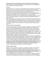
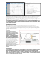
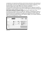
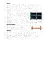
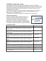
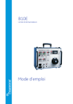
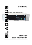
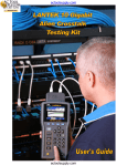
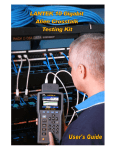
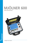
Technical guide
circuit breaker diagnosis
Contents
Introduction to maintaining and testing circuit breakers ................................................3
History of Programma circuit breaker test equipment ..................................................9
DualGround................................................................................................. 10
Product Portfolio ........................................................................................... 11
TM1800 Configuration Guide ............................................................................ 15
Introduction to maintaining and testing circuit breakers
This is a short application briefing intended for anyone who wants to understand the
basic principles of circuit breaker testing.
General
When a fault occurs, current must be interrupted quickly and reliably to avoid personal
injuries and minimize damage. If a breaker fails to break the circuit, the resulting
damage can be very serious indeed. Moreover, a needlessly large section of the power
grid will have to be disconnected in order to interrupt the fault current.
A circuit breaker is the active link in the fault-clearance chain. Even though circuit
breakers are comparatively reliable, faults can and do occur. Circuit breakers must thus
be tested and maintained to ensure operation when a crucial need arises.
During its 40+ year service life, a circuit breaker must be constantly prepared to do its
duty. Long periods of idleness often elapse during which the breaker's mechanical
parts never move.
There are many reasons to maintain and test a circuit breaker. Friction and wear can
affect the performance of movable parts. Leaks can occur in the valves and seals used
in arc-extinguishing chambers, damping devices, pneumatic and hydraulic operating
mechanisms. Faults can occur in electrical control circuits, and the contact surfaces in
current-carrying circuits can deteriorate, thus increasing the risk of excessive heat
generation.
Different maintenance strategies
If a maintenance strategy that is strictly corrective is adopted, no attempts are made to
deal with a developing circuit breaker fault before it becomes fatal. This does not,
however, ensure the reliable supply of electric power that consumers are entitled to
expect. Short-term savings in maintenance costs will soon be eaten up by the cost of
the damage and the cost of correcting faults. In periodic maintenance, a number of
specific measures are taken at predetermined times, regardless of the conditions under
which a circuit breaker operates. If this method is applied too strictly, however, it may
lead to needless intervention. Disassembling a circuit breaker that has no faults entails
needless expense, and it does not improve reliability.
Condition-based maintenance is being used more and more. Here, you ascertain the
condition of a circuit breaker through testing and inspection. The results, supplemented
with statistical data and cumulative experience, are then used to plan maintenance for
the circuit breaker in question. The breaker's need for maintenance is based less on
time than on the conditions to which it is exposed, how frequently it operates and its
environment. Condition-based maintenance provides excellent opportunities to improve
reliability and cut costs, but it requires effective diagnostic methods. Many circuit
breakers provide longer service lives than expected. If you can ascertain that a breaker
is in good condition, you can continue to use it rather than replace it. Here too,
however, effective diagnostic methods are of prime importance.
Testing circuit breakers
Before a new circuit breaker is delivered, it is tested at the factory. After it has been
installed, it is submitted to a commissioning test before being taken into service.
Thereafter, it is inspected and tested on different occasions. Usually, a circuit breaker
has to be taken out of service in order to test it. Lately, however, more and more
interest is generated around the concept of on-line testing, doing certain measurements
on the breaker while it is in active service. More about this later.
The following parameters are often tested on a circuit breaker: closing time, opening
time, and resistance of the main contacts and synchronization of contact operation.
Contact travel and speed are also tested (as recommended in the IEC 1208 standard
and other literature). Some new methods for circuit breaker diagnostics are dynamic
resistance and vibration testing. Moreover, checks are made to see that the solenoids
and latches operate properly. This is done by measuring the lowest breaker operating
voltage and checking the shape of the coil current curve.
Measured values are compared with limit values specified by the manufacturer or
values that have been arrived at by the maintenance organization through experience.
In many cases, a "fingerprint" consisting of different measurements taken when a
breaker is new is compiled. This fingerprint can then be used as a reference for
subsequent measurements. Any change that is found clearly indicates a change in the
breaker's condition.
What needs to be tested on a circuit breaker?
Following are parameters that are recommended in ANSI and IEC standards for
evaluating the condition of high voltage circuit breakers and that can easily be
measured using TM1800.
Timing measurements
Simultaneity within a single phase is important in situations where a number of contacts
are connected in series. Here, the breaker becomes a voltage divider when it opens a
circuit. If the time differences are too great, the voltage becomes too high across one
contact, and the tolerance for most types of breakers is less than 2 ms. The reason is
that the multiple breaks together make a voltage divider (in open position). If the time
spread is too big it will result in over-voltage on a single contact. Serious damages on
the breaking chamber might occur.
The time tolerance for simultaneity between phases is greater for a 3-phase power
transmission system running at 50 Hz since there is always 6.67 ms between zerocrossovers. Still, the time tolerance is usually specified as less than 2 ms, even for such
systems. It should also be noted that breakers that perform synchronized breaking
must meet more stringent requirements in both of the aforesaid situations.
There are no generalized time limits for the time relationships between main and
auxiliary contacts, but it is still important to understand and check their operation. The
purpose of an auxiliary contact is to close and open a circuit. Such a circuit might
enable a closing coil when a breaker is about to perform a closing operation and then
open the circuit immediately after the operation starts, thereby preventing coil burnout.
The a-contact shall close in due time before the main contact closes and the b-contact
shall open at a time safely after the drive mechanism has released its.
The breaker manufacturer will be able to provide detailed information about this cycle.
Motion measurements
A high-voltage breaker is designed to interrupt a specific short-circuit current, and this
requires operation at a given speed in order to build up an adequate cooling stream of
air, oil or gas (depending on the type of breaker). This stream cools the electric arc
sufficiently to interrupt the current at the next zero-crossover. It is important to interrupt
the current in such a way that the arc will not re-strike before the breaker contact has
entered the so-called damping zone.
Example of coil current trace measured
with TM1800
Legend
1
Trip coil energized
2-3 Armature travel
3-4 Armature operates trip latch
4-5 Armature completes its travel
5
Armature hits stop
6
Change in coil inductance
7
Proportional to DC coil resistance
8
Auxiliary contact opens
9
Current decay
Speed is calculated between two points on the motion curve. The upper point lies at a
definite distance from a) the breaker's closed-position or b) the contact-closure or
contact-separation point. The time that elapses between these two points ranges from
10 to 20 ms, which corresponds to 1-2 zero-crossovers.
The distance throughout which the breaker's electric arc must be extinguished is
usually called the arcing zone. From the motion curve, a velocity or acceleration curve
can be calculated in order to reveal even marginal changes that may have taken place
in the breaker mechanics.
Speed and acceleration
The mathematical derivative of motion is speed and the second derivative is
acceleration. The analysis of instantaneous speed and acceleration curves will give a
lot more of information about what happens along the way from open to close position
than the travel curve itself.
Damping
Damping is an important
parameter for the high-energy
operating mechanisms used to
open and close a circuit
breaker. If the damping device
does not function satisfactorily,
the powerful mechanical strains
that develop can shorten
breaker service life and/or
cause serious damage. The
damping of opening operations
is usually measured as a
second speed, but it can also
be based on the time that
elapses between two points just
above the breaker's open
position.
Typical motion diagram for close-open operation
Coil currents
Coil currents can be measured on a routine basis to detect potential mechanical and/or
electrical problems in actuating coils well in advance of their emergence as actual
faults. The coil's maximum current (if current is permitted to reach its highest value) is a
direct function of the coil's resistance and actuating voltage. This test indicates whether
or not a winding has been short-circuited.
When you apply a voltage across a coil, the current curve first shows a straight
transition whose rate of rise depends on the coil's electrical characteristic and the
supply voltage. When the coil armature (which actuates the latch on the operating
mechanism's energy package) starts to move the electrical relationship changes and
the coil current drops.
The peak value of the first, lower current peak is related to the fully saturated coil
current (max current), and this relationship gives an indication of the spread to the
lowest tripping voltage. If the coil were to reach its maximum current before the
armature and latch start to move, the breaker would not be tripped. It is important to
note, however, that the relationship between the two current peaks varies, particularly
with temperature. This also applies to the lowest tripping voltage.
In some cases it is also of interest to measure DC voltage sagging during coil operation.
The figure below shows trip coil current and DC voltage sagging in an open operation.
The open circuit voltage is 128 V and the voltage sag is about 14 V at maximum trip
current 11 A. These are normal values and do not indicate any malfunctions in the DCoperating voltage circuitry.
Trip voltage test
In some situations the supply voltage to the
circuit breaker in the substation is only from the
battery. If the battery is not in good condition the
voltage supply for the circuit breaker can be
lower than specified. It is important that the
circuit breaker is operational for the full supply
voltage interval. This is tested by supplying
increasing voltage in steps and observing the
lowest supply voltage that is enough to
DC voltage sagging during coil
magnetize the actuating coil and trip the CB.
operation
For a coil current test the supply voltage shall be
stable and well known. If the station battery or any other unstable source is used any
strange behavior in the supply voltage may be interpreted as a fault in the actuating coil
or mechanics.
The Programma B10E is a power supply specialized for substation work.
Static contact resistance
Static contact resistance is measured by injecting a DC-current through the breaker
and measure the voltage drop over the contact or joint that is of interest. The IEC
standard requires a current of at least 50 A DC. The ANSI standard says minimum 100
A DC. Some manufacturers recommend 10% of the rated current for the breaker.
There are several reasons for using a high test current. At low currents the measured
values will be the same provided that the resistance is linear vs. the current. The risk is
that low currents might give too high resistance values at some instances.
Such cases can be grease on the contact surface or a polluted contact from rest
products from several breaks of rated current. The references values given by the
manufacturers are static resistance values.
Vacuum bottle integrity test
For circuit breakers with vacuum as insulation it is important to ensure the vacuum
chamber has intact vacuum. If air has leaked into the chamber the circuit breaker may
fail to interrupt a current as it is supposed to. To test the vacuum integrity a high
voltage DC, 20-60 kV, is applied over the open contact. The leaking current is a
measure of the vacuum integrity. VIDAR is the equipment for this test.
DRM — Dynamic resistance measurements
The DRM test method is very suitable for diagnostic testing. Tests are conducted by
injecting DC current through the breaker and measuring the voltage drop and current
while the breaker is operated. The breaker analyzer then calculates and plots
resistance as a function of time. If contact movement is recorded simultaneously, you
can read the resistance at each point of contact. This method is used for contact
diagnosis, and in certain cases it is also used to measure times.
With DRM it is possible to reliably estimate the length of the arcing contact. In SF6 and
air-blast breakers the arcing contact is commonly made of Wolfram (tungsten). This
contact is burned off and becomes shorter for each live operation of the circuit breaker.
A DRM measurement will give you the length of the arcing contact. See the figure
below.
TM1800 is particularly suitable for DRM since the timing channels also measure analog
signals directly. Thus, a minimum number of channels and connections are needed.
Example of dynamic contact resistance measured with TM1800.
Vibration measurements
When a breaker operates, the mechanical motion generates strong vibrations. These
signals can be used for diagnostics and maintenance, and Programma's Breaker
Analysis Software CABA Win makes it possible to perform vibration measurement as a
standard site test.
One or more accelerometers are attached to the breaker poles and operating
mechanism. Vibration signals from the accelerometers proceed via a signalconditioning unit that incorporates an amplifier and filter to the Breaker Analyzer
System TM1800 where they are recorded during breaker operation. The directly
recorded vibration signals can be analyzed in the CABA Win software, together with
time, motion and coil current data. These data alone, however, do not suffice for
determining breaker-condition trends.
A sophisticated procedure known as Dynamic Time Warping (DTW) is used for further
analysis. DTW compares vibration signals with reference signals obtained (preferably)
from a previous test conducted on the very same breaker. However, inter-phase
comparisons and comparisons with the results of tests conducted on other breakers of
the same type can be used in the initial phase of a series of tests. Comparison results
are presented on a time-time diagram that shows time deviations and also on a
deviation diagram that reveals differences in vibration amplitudes.
All test data and analysis data can be reported along with other data such as motion
and speed. The overall results provide a more detailed picture of breaker condition than
has heretofore been available. In this picture you can easily discern deviations that are
beginning to appear and trace their origins.
DTW vibration analysis is available in a separate program module that can be
purchased as an optional add-on for CABA Win. This type of measurement requires a
high sampling rate and a broad dynamic range. The Programma TM1800 uses 14-bit
resolution and 40 kHz sampling rate. Together with Programma's specially designed
Signal Conditioning Amplifier SCA 600, the TM1800 enables you to measure vibrations
with frequencies ranging up to 15 kHz.
Example of vibration measurement. Close
operation
Terminology
Cincinnati testing
Switch sync
analysis
Doctor test
Revolving drum with pen writing. When the circuit breaker operates the drum
rotates and the graph is a travel curve.
ABB controls the breaking time with SwitchsyncTM to occur at a phase angle so
that no relighting and minimum of transients is created when the current is
broken. There is a test kit and application note for analysis of SwitchsyncTM circuit
breakers with TM1800 and TM1600. See also page C-1 in the ABB Product
guide.
Micro ohm meter test. “American English”
History of Programma circuit breaker test equipment
Programma has more than 25 years experience in the field of circuit breaker testing.
Programma pioneered this field in 1977 with the MOM 600A, a micro-ohmmeter for
measuring contact resistance on circuit breakers. The MOM 600A created the company
more than opposite and here is the success story over the years.
1977
1980
1984
1985
1988
1989
1991
1993
1994
1995
1996
1999
2003
2006
2007
Micro ohm measurements with MOM 600A introduced.
B10 Power Supply Unit.
TM16 introduced. The first microprocessor-based breaker analyser.
VIDAR Vacuum Tester. VIDAR test integrity of vacuum bottles.
MA31 Motion Analyser. Module for TM16 that enables measuring analog
entities such as contact travel/velocity and coil currents.
TM1600 replaces TM16. TM1600 enables a larger number of timing channels.
CABA software for DOS. used with TM1600 for facilitating circuit breaker
analysis.
First DRM method on the market method introduced for TM1600.
MA61 replaces MA31. MA61 enables measurement of more analog
parameters simultaneously.
EGIL, an easy-to-use circuit breaker analyser specifically for capable of three
phase, one interrupter per phase and motion.
CABA Win Vibration. Vibration testing of circuit breakers with TM1600.
MUNIN CBM (Circuit breaker monitoring), a stationary device to be mounted
on the circuit breaker permanently. MUNIN is later discontinued.
CABA Win for Windows.
TM1800 introduced.
Mjölner, enhanced micro-ohmmeter.
DRM solution for TM1800.
DualGround is introduced for Timing in TM1800. Also DRM, Micro Ohm
resistance and Vibration methods are possible with both sides grounded.
DualGround
The DualGround trademark is used on equipment and
methods that is adopted for safe, fast and easy
operation with both sides grounded throughout the test.
All diagnostic test on CB with DualGround
Programma provides instrumentation that makes
DualGround measurement possible for all diagnostic test
on circuit breakers.
Measurement
Timing
DualGround
TM1800 with DCM
Motion, aux contacts,
coil current…
OK with conventional methods.
Micro ohm
Mjölner with the 4 wire + CT
DRM
High current with DRM1800
Vibration
The vibration solution from Programma works with
both sides grounded.
Continued reading
There are a number of internal and external publications available in the Sales Binder
Library. Some examples:
• Employee Safety Concerns in the Electrical Supply Industry: How new
technology can keep your managers out of court, support your corporation’s
stock price — and keep your HV test engineers alive. (White paper)
• PowerPoint presentation DualGround.
• The TM1800 pamphlet and the catalogue.
Programma product portfolio
Circuit breaker analyzers
Programma provides a complete portfolio of test equipment for circuit breaker testing.
There are three circuit breaker analyzers, TM1800, EGIL and TM1600 within the
Programma brand. EGIL for three phase circuit breakers with one interrupter per phase
and one motion. TM1800 for all more demanding applications. Two versions of EGIL
are available, with and without analog module and PC interface. For TM1800 the
configuration can be adopted to very specific requirements. There are eight slots for
modules. Available modules are Control, Timing M/R, Analog, Digital, Timing AUX and
Printer. Typical configurations are shown in the figure below.
CABA Win is available for TM1800, EGIL and TM1600. DRM1800 and CABA Win
Vibration are available for TM1800 and TM1600.
For all levels of challenge there is a suitable configuration within the Programma Circuit
Breaker analyzer portfolio.
Key benefits
•
•
•
•
•
Routine Testing
Service
Maintenance
•
Suitable
DualGround timing. (See several separate
application
documents)
domain
Active Interference Suppression makes test
result reliable even in rough field conditions
with high interference levels. (See separate
white paper.)
OEM
Select-Connect-Inspect workflow and highGeneration
level user interface makes testing fast and
Transmission
easy. Reduced need for operator training.
Distribution
Stand-alone functionality. Be fully equipped
Contractors
with one unit.
Industry
Modular concept. Adapt to user needs, pay
as you grow, enjoy future development.
Ethernet between TM1800 and PC with CABA Win ensures speed and reliability.
USB interface enables easy backup and data exchange. ontractors
Commissioning
•
Development
Manufacturer
New!
TM1800
TM1800 is robust and reliable for field use. The
flexibility of TM1800 makes it suitable for testing
both in development, production, commissioning
and maintenance of circuit breakers.
The Select-Connect-Inspect three step
measurement method makes testing fast and fun.
TM1800, TM1600 and EGIL are all fully
compatible with CABA Win. Many transducers can
also be used on all the three breaker analyzers. A company can have a mixture of
TM1800, EGIL and TM1600. Tests will be perfectly comparable in CABA Win
independent of the instrument used for recording.
Circuit breaker manufacturers, electric utilities and service companies appreciate the
flexibility of TM1800. The varying demands are fulfilled by configuration of TM1800 for
there individual needs. Up to 48 + 48 timing channels can be configured. For OEM and
other R&D activities there is special internal software available that makes it possible to
operate the CB 5000 times and record every 20th operation.
TM1800 is fully compatible with CABA Win Vibration and DRM1800. Please note that
there is not a calibration module available for TM1800, but an instruction on how to
verify the calibration data with normal laboratory equipment.
Among the latest improvement is a weight reduction (by better material usage) bringing
the TM1800 Basic Unit to 11,5 kg.
Language
TM1800 is available with internal software and User Manual on English, Swedish,
French, German and Spanish.
EGIL
EGIL is intended for three phase circuit breakers
with one interrupter per phase.
In addition to timing the coil current is captured
automatically. The measurement results are printed
in table and graph on the internal printer. With the
analog module installed, motion or any other analog
signal can be captured. Velocity is calculated.
Evolution of circuit breakers has made it possible to
interrupt a 220 kV current with one single
interrupter. With this the application area of EGIL
grows. Especially for GIS the application area has increased.
EGIL uses a 100 mA current for measurement. This relatively strong signal current is
required to withstand interference present in high voltage substations. 100 mA is well in
line with requirements and competition. EGIL has been proven to work well in 220 kV
outdoor switchyards and even 400 kV indoor GIS.
It is not recommended to do vibration testing with EGIL because the analog channel is
not sensitive enough.
Language
EGIL is available with internal software and User
Manual on English, Swedish, French, German
and Spanish.
OEM
Generation
Transmission
Distribution
Contractors
Industry
Routine Testing
Suitable
application
domain
Service
Maintenance
•
Extremely easy-to-use.
Stand-alone functionality reduces the number
of items and boxes the tester needs to bring
to the field.
Portable, rugged design – suitable for fieldtesting.
Commissioning
•
•
Development
Manufacturer
Key benefits
TM1600
Introduced in 1989 with over 3000 deliveries all over the world this is by far the most
used circuit breaker analyzer. The proven reliability in harsh conditions and easy
operation has been fundamental for the success.
TM1600 is a good choice when cost is critical and the high end user interface, superior
measurement accuracy and advanced functionality of TM1800 is not necessary.
CABA Win
CABA Win is the advanced software for measurement
assistance, advanced analysis, report generation and
data storage. Connection with TM1800 over Ethernet is
very fast and secure. Parameters and pass-fail limits can
be modified on recordings. CABA Win is a superior
interpretation tool where comparison and detailed studies
are made. For backup purpose the database is perfect.
TM1800 template for specific circuit breakers can be
created. A test plan guides the user through the measurement and contains all specific
thresholds and parameters.
CABA Win is the strongest software on the market for circuit breaker testing. CABA Win
requires a PC computer and is compatible with TM1800, EGIL and TM1600.
CABA Win Vibration
The vibration software CABA Win Vibration is used for
easy interpretation of vibration recordings.
TM1800 or TM1600 together with CABA Win and the
vibration solution is required for vibration test.
DRM1800
With DRM the arcing contact condition and overlap length is evaluated without
dismantling the breaker. Problems with contact fingers, lubrication and SF6 exhaust
contaminations is detected. DRM1800 is reduced in weight with 70% to the previous
solution. Built in battery and short cables makes this perfect for commissioning work.
DRM1800 is compatible with TM1800 and TM1600. DRM1800 give advantages
together with TM1800 that is not present with TM1600.
TM1800 configuration guide
The TM1800 system is fully modular with high flexibility to configure TM1800 for
specific duties. The choice of modules shall be based on the kind of circuit breaker that
will be tested, parameters to be recorded and the templates to be used. The basic unit
needs at least one module to become functional. It is very easy to find the correct
configuration for any situation.
The basic unit has 8 slots for modules. Modules can be placed in any of the module
slots 1 to 8. Slot number 9 in the module panel is specially designed for future
development of a calibration module.
GE recommends using TM1800 together with CABA Win an all applications.
Standard configurations
The figure has typical cases in black on the top. It is
number of contacts per phase and always times three
phases for main contact timing. 2x3xTime shall be
understood as Timing of 2 contacts per phase on 3
phases. Below is number of motions to measure. When
there is one contact per phase EGIL is a good alternative
for TM1800. The figure is available in larger format above.
Configuration Table
To be measured with TM1800
Required modules
Operate close and open with common mechanism
Measure coil currents, supply voltage, resistance and auxiliary
contact timing.
1 Control
Operate close and open with separate mechanism for 3 phases
Measure coil currents, supply voltage, resistance and auxiliary
contact timing.
2 Control
Main contact timing and parallel resistor contact timing including
parallel resistor measurement for 3 phase with 1-2 breaks per
phase
1 Timing M/R
Main contact timing and parallel resistor contact timing including
parallel resistor measurement for 3 phase with 3-4 breaks per
phase
2 Timing M/R
Main contact timing and parallel resistor contact timing including
parallel resistor measurement for 3 phase with 5-6 breaks per
phase
3 Timing M/R
1-3 motions or any other analog signals
1 Analog
4-6 motions or any other analog signals
2 Analog
1-6 motions or other incremental digital transducer (RS422)
1 Digital
6 auxiliary contact timing (in addition of what is measured with
control modules)
1 Timing Aux