1
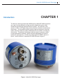
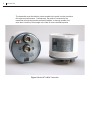
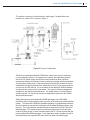
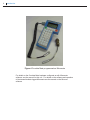
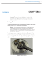
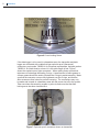
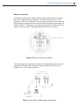
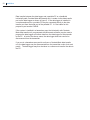
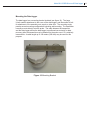
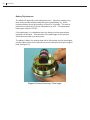
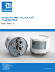
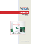
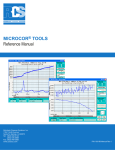
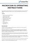
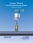
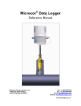
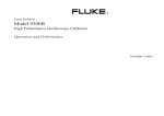
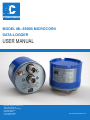
MODEL ML-9500B MICROCOR®
DATA-LOGGER
USER MANUAL
Rohrback Cosasco Systems, Inc.
11841 Smith Avenue
Santa Fe Springs, CA 90670
Tel: (562) 949-0123
(800) 635-6898
Fax: (562) 949-3065
www.cosasco.com
P/N 702180-MANUAL Rev C
MICROCOR® is a registered trademark of Rohrback Cosasco Systems, Inc.
Windows® is a trademark of Microsoft Corporation.
No part of this manual may be reproduced or transmitted in any form or by any means,
electronic or mechanical, including photocopying and recording, for any purpose, without
the express written permission of Rohrback Cosasco Systems, Inc.
Model ML-9500B Microcor® Data-logger
Table of Contents
Chapter 1 Introduction ............................................................................1
Chapter 2 Specification ...........................................................................5
Chapter 3 Installation ..............................................................................7
Datalogger Enclosure...................................................................................7
Mounting the Datalogger..............................................................................11
Battery Replacement.................................................................................. 12
Chapter 4 Operation ...............................................................................13
Troubleshooting ....................................................................................... 13
Appendix A Compatibility .........................................................................15
Appendix B ATEX Certification ..............................................................17
i
ii
Table of Contents
Model ML-9500B Microcor® Data-logger
CHAPTER 1
Introduction
The Microcor data-logger Model ML-9500B and the Model MT-9485A transmitter
are a part of a new generation of high-resolution digital instruments, which
operate with special high-resolution Microcor probes. The resolution of the
system is 18 Bit, or 256 higher than previous electrical resistance measurement
instruments. This increased resolution greatly improves response to corrosion
upsets, and at the same time allows measurements to be made in virtually any
environment. The patented technology combines speed of response, similar
to linear polarization resistance, with the universal applicability of electrical
resistance measurements. The Microcor Data-logger ML-9500B is shown in
figure 1, and the Microcor Transmitter MT-9485A is shown in figure 2.
Figure 1 Model ML-9500B Data-logger
1
2
Introduction
The transmitter must be relatively close-coupled to the probe in order to achieve
this improved performance. Consequently, the probe is connected to the
transmitter through short probe-connecting adapter, or through a cable of no
more than 2 meters (6 feet) length in the case of some retractable probes.
Figure 2 Model MT-9485A Transmitter
Model ML-9500B Microcor® Data-logger
The system connection of the transmitter, data-logger, Corrdata Mate data
transfer unit, and the PC is shown in figure 3.
Figure 3 System Configuration
The Microcor transmitters Model MT-9485A are used on their own for continuous
on-line monitoring systems. For these on-line systems, the transmitters operate
with a 24 VDC power supply and RS 485 communications to allow multi-drop
connections between the central corrosion monitoring computer and the transmitters.
This minimizes cabling costs. Each transmitter has internal DIP switches to set the
Identification Number or Address of the transmitter from 0 to 31 for communications
over the two-wire RS 485 bus. For more details on the Model MT-9485A hardware,
see the instruction manual for the transmitter. Two types of software packages are
available for use with the transmitter alone. For simple systems, see the Microcor
software manual. For full on-line corrosion management systems see the ICMS3/
Amulet software manual.
Adding the battery powered Model ML-9500B data-logger to the MT-9485A
transmitter with an interconnecting cable, provides for an autonomous data collection
system. The Model ML-9500B has the added capability of simplified data collection
from the hazardous area with the intrinsically safe Corrdata Mate data collector (see
figure 4). The communication operates through an intrinsically safe RS 232 port on
the data-logger. This avoids the need to remove the data-logger to the safe area
under a hot work permit, in order to transfer data to the PC, as was required with the
previous Model ML-9500 data-logger. In non-hazardous areas, the data may still be
collected directly with a portable PC and connection cable to the data-logger.
3
4
Introduction
Figure 4 Corrdata Mate programmed as Micromate
For details on the Corrdata Mate hardware configured as with Micromate
software, see the manual for this unit. For details on the software and operation
of the transmitter/data-logger/Micromate see the manual on the Microcor
software.
Model ML-9500B Microcor® Data-logger
Specification
CHAPTER 2
Data-logger Model ML-9500B
• Enclosure NEMA 7 and IP 66/ NEMA 4X
• Weight 3.5 lbs (1.6 Kg)
• Dimensions 4.5” (115mm) Diameter by 4.25” (108 mm)
High including connectors
• Power supply 3.6 V 16Ah Lithium battery
• Quiescent current data-logger and transmitter 0.4 mA
• Approximate current during probe reading 100 mA for 1 minute
• Approximate current during data transfer 40 mA
• Battery Life at one reading per hour - approx. minimum 6 months
• Battery life at one reading every three hours - approx.
minimum 12 months
• Maximum data storage capacity 8,000 readings
• Transmitter Communication RS 485 two-wire 2400 Baud,
8 data bits, 1 stop bit, no parity
• Proprietary communications protocol
• Resolution 18 bit (1 part in 262,144)
• Ambient temperature range -40C to +70C (-40F to 158F)
• Hazardous area classification EExd [ia] IIC T4
• Wall mount and pole mounting bracket included
• Maximum transmitter to data-logger cable length
100 meters (300 feet)
5
6
Specification
Model ML-9500B Microcor® Data-logger
CHAPTER 3
Installation
Important: This manual covers installation and operation of the
model 9500B data-logger and model 9485A transmitter only. See
Appendix A for compatibility with other data-logger and transmitter
model combinations.
Data-logger Enclosure
The Microcor data-logger enclosure is explosion-proof (flameproof), and is sealed
with an O-ring so as to be gas-tight when fully tightened
Warning: It is very important to make sure that the data-logger cover
is fully tightened down on to the O-ring seal, to avoid in-leakage of
water or moist air that may subsequently cause condensation. Water or
condensation is likely to cause malfunction of the data-logger and even
corrosion of the electronics.
The data-logger cover can be tightened, with the aid of a 2” center by 1/4” pin
spanner wrench on the base of the unit, and by hand or with a 3/8” square bar
or similar on the cover (see figure 5). The cover of the data-logger can be locked
in place with the 5/64 Allen screw. See Figure 6. This is a requirement of the
explosion-proof (flameproof) enclosure to prevent accidental loosening of the
cover.
Figure 5 Spanner Wrench
7
8
Installation
Figure 6 Cover Locking Screw
If the data-logger is to be used in a hazardous area, the transmitter and datalogger are connected with a cable that has explosion-proof (flameproof)
connectors, part number 748202-LL for European requirements, and part number
748203-LL for North America, where LL is the cable length in feet. Figure 7
shows the explosion-proof type connectors. When making these connections,
take care not to damage the sealing O-rings. A small amount of white grease or
silicone grease should be used to lubricate the O-rings to assist assembly. Make
sure that the connector nuts are fully tightened over the O-rings, and that the
Allen screws are then locked to prevent loosening. The connections may only
be made and unmade in a hazardous area with the power shut off to the system.
Take care when disconnecting a cable or probe to make sure that the Allen
locking screw has been loosened first.
Figure 7 Explosion-proof connectors shown on transmitter
Model ML-9500B Microcor® Data-logger
Battery Connection
The Microcor data-logger is shipped with the battery disconnected, and before
first use, the battery must be connected. This should only be done in a nonhazardous, clean area. Verify the set screw is loose, and then remove the cover.
Plug the battery connector into the connector below the battery support plate, as
shown in Figure 5. Replace the cover and fully tighten down on the O-ring, and
tighten the set screw (see “Data-logger Enclosure” section on page 6).
Figure 8 Battery Connection Location
If the data-logger and transmitter are used in a non-hazardous area, then a non
explosion-proof cable can be used part number 748209- LL where LL is the
length in feet. This is shown in figure 9.
Figure 9 Transmitter & Data-logger Connections
9
10
Installation
Data transfer between the data-logger and a portable PC or a handheld
intrinsically safe Corrdata Mate data transfer unit, is made via the data transfer
port on the data-logger as shown in figure 5. If the data-logger is installed in
a non-hazardous area, a portable PC may be connected directly to the data
transfer port from the serial port of the portable PC. A 5 foot cable for this
purpose is part number 748243.
If the system is installed in a hazardous area, the intrinsically safe Corrdata
Mate data transfer unit, programmed with Micromate software, may be used to
program the data-logger and collect data from the data-logger for later transfer
to the PC. In both of the above cases, the data-logger does not need to be
disconnected from the transmitter.
If you are in a hazardous area and do not have a Corrdata Mate data transfer
unit, the data-logger may be disconnected from the transmitter under a hot work
permit. The data-logger may then be taken to a safe area to transfer the data to
the PC.
Model ML-9500B Microcor® Data-logger
Mounting the Data-logger
The data-logger has a mounting bracket included (see figure 10). The large
U-bolt enables attachment to the cover of the data-logger, and the smaller U-bolt
for attachment of the assembly onto a pole or other strut. The mounting angle
permits several mounting configurations including wall mounting. The transmitter
normally mounts directly onto the probe. The cable between the transmitter
and the data-logger allows the data-logger to positioned conveniently for data
recovery while the transmitter may be attached to the probe even if it is relatively
inaccessible. A cable length up to 100 meters (300 feet) may be used for this
purpose
Figure 10 Mounting Bracket
11
12
Installation
Battery Replacement
The battery life depends on the reading frequency. Typically a reading every
three hours provides sufficient data and gives a good battery life. At this
frequency battery life will be typically a minimum of 12 months. This may be
reduced to as much as 50% at low temperatures of -40C. The replacement
battery part number is 702167.
If the data-logger is in a hazardous area, the battery must be removed and
replaced in a safe area. Disconnection of the data-logger for this purpose
should be done under a hot work permit.
The battery is held in the support plate with a Velcro strap, and can be plugged
into the battery socket on the electronics circuit board below the battery support
plate (see figure 11).
Figure 11 Battery Mounting in Data-logger
Model ML-9500B Microcor® Data-logger
13
CHAPTER 4
Operation
The Microcor data-logger Model 9500B is generally set up and read with the
Corrdata Mate or Mate II configured with Micromate software. The Corrdata
Mate or Mate II is intrinsically safe and allows the data-logger to be set up and
read in a hazardous area, whereas direct connection of a portable PC does not.
The Corrdata Mate allows collection of data from multiple data-loggers in the
field, for subsequent transfer to the PC, running Microcor software. For detailed
operation of this software, refer to the applicable manual.
The Microcor software has four programs as follows:
1. Micrec.exe - For direct on-line recording and display of readings from a single transmitter.
2. Micnet.exe - For direct reading and logging of data from multiple modules.
3. Miclog.exe - For transferring data from a data-logger to the PC
4. Micret.exe - For displaying stored data files
Make sure that the battery in the data-logger has been connected before
configuration (see figure 10)
Troubleshooting
If communication cannot be established with the data-logger, replace the battery
and recheck the operation.
If abnormal readings, or an excursion occurs that cannot be explained, the
system electronics may be verified by connecting the meter prover in place of the
probe and checking that the reading corresponds. See “Checking Operation with
Meter Prover” in Chapter 3 Installation of the Microcor transmitter manual.
If the meter prover shows the electronics to be operating correctly, then inspect
the probe to transmitter connections, and the probe for damage, high resistance,
or poor connections.
After initial application of power, the transmitter takes approximately one minute
to start up during which time it will send the error code -999,999 when its data is
requested.
If there is a probe or probe connection failure an error codes -999,998, or
-999,997 may be generated. See the transmitter manual for more details.
14
Operation
Model ML-9500B Microcor® Data-logger
Appendix A
Compatibility
The Microcor data-logger model 9500B is designed to be used with the model 9485A Microcor
transmitter. If you are using a model 9500A data-logger with a model 9485 transmitter, please
see the Users Manual for the model 9500A data-logger (RCS P/N 702150-MANUAL).
When using the model 9500B data-logger, use only cables between the data-logger and the
Mate data-collection unit, or between the data-logger and a personal computer that are labeled
“FOR MICROCOR ML-9500B DATALOGGERS” Use of other cables will not function properly
and may damage the unit. The correct cable part numbers are listed below:
Model 9500A
Data-logger to Mate
Data-logger to P.C.
Cable P/N 748206
Cable P/N 748204
Model 9500B
Data-logger to Mate
Data-logger to P.C.
15
Cable P/N 748241
Cable P/N 748243
Both model data-logger to Mate cables are included in the Mate unit kit, and labeled
appropriately. If cables to connect to a P.C. are required, contact the factory.
The model 9500B data-logger may be used with either a model 9485A transmitter, or with the
older model 9485 transmitter. Also, the older model 9500A data-logger may be used with either
the model 9485A or 9485 transmitter. However, when using the older 9500A data-logger with
the newer 9485A transmitter, battery life in the data-logger will be reduced.
16 Compatibility
Model ML-9500B Microcor® Data-logger
ATEX Certification
17
Appendix B
18 ATEX Certification
Model ML-9500B Microcor™ Data-logger
19
20 ATEX Certification
Model ML-9500B Microcor™ Data-logger
21
22 ATEX Certification