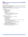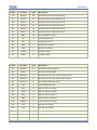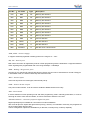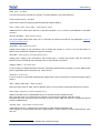
1
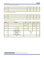
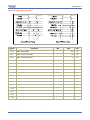
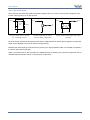
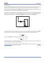
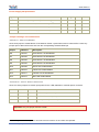
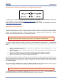
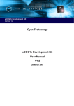
SmartVR User Manual Release 2.0 www.veear.eu www.veear.eu Table of Contents SmartVR Module .............................................................................................................................................. 3 Product Description ........................................................................................................................................ 3 Technical specifications ................................................................................................................................. 4 Physical dimensions and Pin configuration ............................................................................................... 4 Pin description ........................................................................................................................................... 4 Recommended Operating Conditions ....................................................................................................... 8 Power Supply Requirements ..................................................................................................................... 8 Electrical DC Characteristics ..................................................................................................................... 8 Electrical AC Characteristics ..................................................................................................................... 9 Using an external microphone ................................................................................................................. 10 Audio Output ............................................................................................................................................ 12 General Purpose I/O ................................................................................................................................ 13 Flash Update ........................................................................................................................................... 15 SmartVR Development Board ...................................................................................................................... 16 Product Description ...................................................................................................................................... 16 Technical specifications ............................................................................................................................... 16 Physical dimensions and layout .............................................................................................................. 16 Recommended Operating Conditions ..................................................................................................... 16 Power Supply Requirements ................................................................................................................... 17 Jumper settings and connections ............................................................................................................ 17 Connecting an external microphone to the Development Board ............................................................. 19 Updating DevBoard firmware................................................................................................................... 19 DevBoard Schematics.................................................................................................................................. 20 Running your first project............................................................................................................................. 21 SmartVR Software ......................................................................................................................................... 25 Product Description ...................................................................................................................................... 25 QuickT2SI-Lite Users ............................................................................................................................... 25 How to get support ........................................................................................................................................ 26 2 SmartVR User Manual (2.0) www.veear.eu SmartVR Module Product Description The SmartVR module is a development platform for speech synthesis and voice recognition applications, based on Sensory RSC-4128 mixed signal processor. Its small size of 42 x 72 mm and the two connectors at the edges with 2.54mm pin spacing, make it suitable for prototype boards and breadboard friendly. Factory programmed with upgradeable Virtual Machine firmware, it enables easy and low-cost development for a wide variety of applications, with focus on speech and voice recognition. SmartVR hardware: RSC-4128 (with ROM Bootloader) 512KB Code/Const Flash 512KB Data Flash (Serial) 128KB External RAM Full access to RSC-4x I/O pins Expansion bus: allows faster SPI interface to MMC cards 5 dedicated chip select outputs (1 used for MMC on DevBoard) 2 memory enable outputs (1 used for MMC on DevBoard) 8-bit wide, read-write memory bus SmartVR firmware (Virtual Machine): VeeEm: Stack based, no Floating Point, 16-bit Virtual Machine Modified Harvard architecture: 64KB Code / Near-Const memory 64KB Data memory 1MB Far-Const memory Native runtime support for: TM Support for most of Sensory's FluentChip library functions (T2SI, SD, SV, SX, RPMSG) Some C Runtime functions (integer math, strings) Serial Flash and EEprom memory access Fast SPI access to DevBoard memory-card socket (SD/SDHC/MMC) Generic I2C and SPI bus access (up to 5 SPI slaves) Access to general purpose I/O pins Asynchronous serial interface (9600 – 230400 baud) on any I/O pin Programmable in Standard C language (with extensions) Max 64KB program / 64KB volatile data memory TM TM Up to 320KB read-only data (QuickT2SI , QuickSynthesis data) Up to 512KB read-write data (SD, SV, RPMSG) User Manual (2.0) SmartVR 3 www.veear.eu Technical specifications Physical dimensions and Pin configuration 1L 1R 72 mm 28L 28R 42 mm Pin description 4 Pin No. Pin name Type Description 1L VDD P DC input voltage 2L GND P Ground 3L /RST - Asynchronous reset 4L PLED O Power LED indicator 5L VLED O Voice LED indicator 6L GPIO16 I/O General purpose input/output pin 16 7L GPIO15 I/O General purpose input/output pin 15 8L GPIO14 I/O General purpose input/output pin 14 9L GPIO13 I/O General purpose input/output pin 13 10L GPIO12 I/O General purpose input/output pin 12 11L GPIO11 I/O General purpose input/output pin 11 12L GPIO10 I/O General purpose input/output pin 10 13L GPIO09 I/O General purpose input/output pin 09 14L GPIO08 I/O General purpose input/output pin 08 15L GPIO07 I/O General purpose input/output pin 07 SmartVR User Manual (2.0) www.veear.eu Pin No. Pin name Type 16L GPIO06 I/O General purpose input/output pin 06 17L GPIO05 I/O General purpose input/output pin 05 18L GPIO04 I/O General purpose input/output pin 04 19L GPIO03 I/O General purpose input/output pin 03 20L GPIO02 I/O General purpose input/output pin 02 21L GPIO01 I/O General purpose input/output pin 01 22L DBG I/O Debug/diagnostic output 23L TX O Serial port transmit 24L RX I Serial port receive 25L PDN O Power down indicator 26L /XM I Boot mode selector 27L PWM0 O Speaker output 28L PWM1 O Speaker output Pin No. Pin name Type 1R MICRET P Microphone signal reference 2R MICIN I Microphone input signal 3R MICPWR P Microphone power (for on-board gain resistor) 4R MICVDD P Microphone power (for custom gain resistor) 5R DACOUT O DAC audio output (line level) 6R FCK O External SPI fast clock 7R /RDF O Memory bus read strobe 8R /WRD O Memory bus write strobe 9R /EN1 O Memory device enable 1 10R EN2 O Memory device enable 2 11R SPISW O External SPI clock switch 12R /CS1 O SPI bus chip select 1 13R /CS2 O SPI bus chip select 2 14R /CS3 O SPI bus chip select 3 15R /CS4 O SPI bus chip select 4 16R /CS5 O SPI bus chip select 5 User Manual (2.0) Description Description SmartVR 5 www.veear.eu Pin No. Pin name Type Description 17R DQ0 I/O Memory bus data line 18R DQ1 I/O Memory bus data line 19R DQ2 I/O Memory bus data line 20R DQ3 I/O Memory bus data line 21R DQ4 I/O Memory bus data line 22R DQ5 I/O Memory bus data line 23R DQ6 I/O Memory bus data line 24R DQ7 I/O Memory bus data line 25R SDA I/O I2C bus data line 26R MISO I SPI bus data line 27R MOSI O SPI bus data line 28R SCK/SCL O SPI bus clock / I2C bus clock VDD, GND – Power supply It supports externally regulated or battery power in the range 2.7V – 3.6V RX, TX – Serial port Main serial connection for application protocol or flash programming with the bootloader. It supports standard UART signaling with programmable rate in the range 2400bps – 230400bps DBG – Debug / Diagnostic port At power-up it is sampled for Diag-Enable function (active low) and can be activated as a normal TxDiag pin. In bootloader mode, it is held low internally and cannot be used. /RST – Reset input Active-low asynchronous reset signal, with internal pull-up. PDN – Power Down output Low power mode indicator. It can be used to shutdown additional external circuitry. /XM – Boot mode It selects between normal operating mode and flash programming mode. Internally pulled-down, it must be held high at reset to enter the boot-loader, or left unconnected to start the user code. GPIO01-GPIO16 – General purpose digital I/O pins Digital input/output pins available for connections to external hardware. After reset all pins are inputs with light internal pull-up (~200 kΩ). In bootloader mode they are programmed as Hi-Z inputs (within around 10μs). Various configuration options are available for pin direction, internal pull-up, wake-up capability. 6 SmartVR User Manual (2.0) www.veear.eu SDA, SCL – I2C Bus 2 Two-wire synchronous serial bus for simple I C master operation over external devices. SCK, MOSI, MISO – SPI Bus Synchronous serial bus supporting Serial Peripheral Interface Mode 0. /CS1, /CS2, /CS3, /CS4, /CS5 – Chip Select lines Additional lines to select slave devices on the SPI bus.(Note /CS5 is used on the DevBoard for the MMC circuitry). MICIN, MICRET – Microphone Input This is the single-ended audio input port for connecting an external microphone (see paragraph USING AN EXTERNAL MICROPHONE ). MICPWR – Microphone Power Analog power supply for the microphone, with a default gain resistor of 1.2 kΩ. It can be tied directly to MICIN, when used with the default microphone sensitivity. MICVDD – Microphone Voltage Reference Analog power supply for the microphone, with external gain. A custom gain resistor must be connected between this pin and MICIN, with a suitable value for the selected microphone. PWM0, PWM1 – Speaker Out It can be used as a differential audio output line, with direct speaker driving capability, or as two PWM output 1 pins for application specific purposes (e.g. motor control) . DACOUT – Line Out It can be used as an externally amplified high quality audio output or optionally as a general purpose analog output1. /RDF, /WRD, DQ0-DQ7 – Memory Bus Data and control lines for “data” memory address space. It can be used to map external devices in memory. /EN1, EN2 – Memory device Enable lines Address decoded lines to enable/disable access to external memory-mapped devices. /EN1 goes low when A19, A18 and A17 are all high. It is used for the external “Fast SPI” circuit. EN2 goes high when A19 and A18 are both high. It may be used in AND with /EN1 for an additional external memory-mapped device. SPISW, FCK – “Fast SPI” control lines A fast serial clock line (~2.4MHz) and a control line to switch between slow/fast clock. These signals are used together with SCK, MISO, MOSI to control external circuitry implementing a “Fast SPI” bus. 1 Only the audio output function is available with standard firmware. User Manual (2.0) SmartVR 7 www.veear.eu Recommended Operating Conditions Symbol Parameter Min Typ Max Unit VDD DC Input Voltage 2.7 3.3 3.6 V TA Ambient Operating Temperature Range 0 25 70 °C Min Typ Max Unit Power Supply Requirements Symbol Parameter IIDLE Sleep current IDD Operating current 2 <1 mA 11 mA Electrical DC Characteristics Symbol Typ Max Unit GPIO Input Low Voltage -0.1 0.75 V VIH GPIO Input High Voltage 0.8 × VDD VDD + 0.3 V VOL GPIO Output Low Voltage (IOL = 8 mA) 0.5 V VOH GPIO Output High Voltage (IOH = -8 mA) RPD 8 Min VIL RPU 2 Parameter VDD - 0.7 Pull-up resistance GPIO01-GPIO16 DQ0-DQ7, /RDF, /WRD /RESET PWM0, PWM1 Pull-down resistance /XM V 10, 200, Hi-Z 100 50 10 1 k Ω k Ω Module running VM firmware, no outputs loaded, no audio processing SmartVR User Manual (2.0) www.veear.eu Electrical AC Characteristics Symbol Parameter TRLRH /RDF Pulse Width TRLAV1 Min Max Unit 140 ns /RDF Low to /EN1 valid 22 ns TRLAV2 /RDF Low to EN2 valid 11 ns TALRAX1 /EN1 hold after /RDF 17 ns TALRAX2 EN2 hold after /RDF 6 ns TRAVDV1 /EN1 valid to Valid Data In 93 ns TRAVDV2 EN2 valid to Valid Data In 104 ns 0 ns 140 ns TRHDX Data Hold after /RDF TWLWH /WRD Pulse Width TAVWL1 /EN1 Valid to /WRD 18 ns TAVWL2 EN2 Valid to /WRD 29 ns TALWAX1 /EN1 Hold after /WRD 52 ns TALWAX2 EN2 Hold after /WRD 41 ns TWDVAV1 Write Data Valid to /EN1 Valid 22 ns TWDVAV2 Write Data Valid to EN2 Valid 11 ns TWHQX 0 Data Hold after /WRD User Manual (2.0) 35 SmartVR ns 9 www.veear.eu Using an external microphone Selecting a proper microphone and its source resistor are essential for achieving good recognition results. This paragraph describes the procedures for calculating the optimal resistor value and provides guidelines for correct mechanical placement of an external microphone. An external microphone must be connected with proper source resistor (Rs), as follows: MICPWR is the analog power supply for the microphone, with a default gain resistor of 1.2 kΩ. It can be tied directly to MICIN, when used with the default microphone. If another resistor value is needed, use MICVDD instead, as in the above picture. Calculating source resistor Rs You can calculate the microphone source resistor using the formula below: Rs is the optimal microphone source resistor I is the impedance rating of the microphone G is the desired overall system gain, defined as follows: 1. If the program source code is configured for “HEADSET” microphone distance (typically a few centimeters from the user’s mouth), then the overall system gain should be -49 dB (0dB=1v/Pa@1KHz); 2. If the program source code is configured for "ARMS_LENGTH" microphone distance (typically 60-90 cm from the user's mouth – this is the default setting in SmartVR firmware), then the overall system gain should be -44 dB; 3. If the program source code is configured for "FAR_MIC" microphone distance (up to about 3 meters from the user's mouth), then the overall system gain should be -43 dB. S is the sensitivity rating of the microphone you want to use, and it is specified in –dB in the microphone’s 3 specification 3 Converting uBars to Pascal: microphone manufacturers specify the sensitivity referencing to uBars or Pascal. If the microphone sensitivity is referenced to uBars, simply add 20 dB to the rating. For example, -58 dB/uBars + 20dB = -38 dBV/Pa. 10 SmartVR User Manual (2.0) www.veear.eu Example with recommended microphone: The microphone used on the SmartVR DevBoard is an omnidirectional electret condenser microphone (Horn EM9745P-382): Sensitivity -38dB (0dB=1V/Pa @1KHz) Load Impedance 2.2K Operating Voltage 3V Almost flat frequency response in range 100Hz – 20kHz Therefore the optimal microphone source resistor for "ARMS_LENGTH" microphone distance is: – Use the closest standard 5% resistor to Rs. In this example, it would be 1.1 kΩ. The DevBoard uses a 1.2 kΩ resistor to allow use of “FAR” settings in the user’s programs without replacing resistor. Sometimes you might also need to compensate for a voltage lower than the microphone ratings (using a larger resistor value sets a higher input gain). Mounting guidelines Please note that improper acoustic positioning of the microphone will reduce recognition accuracy. Many mechanical arrangements are possible for the microphone element, and some will work better than others. When mounting the microphone in the final device, keep in mind the following guidelines: 1. Flush Mounting - The microphone element should be positioned as close to the mounting surface as possible and should be fully seated in the plastic housing. There must be no airspace between the microphone element and the housing. Having such airspace can lead to acoustic resonance, which can reduce recognition accuracy. GOOD BAD cavity 2. No Obstructions, Large Hole - The area in front of the microphone element must be kept clear of obstructions to avoid interference with recognition. The diameter of the hole in the housing in front of the microphone should be at least 5 mm. Any necessary plastic surface in front of the microphone should be as thin as possible, being no more than 0.7 mm, if possible. clear area Internal diaphragm User Manual (2.0) SmartVR 11 www.veear.eu 3. Insulation - The microphone should be acoustically isolated from the housing if possible. This can be accomplished by surrounding the microphone element with a spongy material such as rubber or foam. The provided microphone has this kind of insulating foam. The purpose is to prevent auditory noises produced by handling or jarring the device from being “picked up” by the microphone. Such extraneous noises can reduce recognition accuracy. GOOD BAD Absorbent material Fastened directly 4. Distance - If the microphone is moved from 15 cm to 30 cm from the speaker’s mouth, the signal power decreases by a factor of four. The difference between a loud and a soft voice can also be more than a factor of four. Although the internal preamplifier of the SmartVR compensates for a wide dynamic range of input signal strength, if its range is exceeded, the user application can provide feedback to the speaker about the voice volume. Audio Output The SmartVR PWM output interface is capable of directly driving an 8Ω speaker. It could also be connected to an external audio amplifier to drive lower impedance loudspeakers, but for this purpose the DAC output is recommended. Note: Connecting speakers with lower impedance directly to the module may permanently damage the SmartVR audio output or the whole module. It is possible to connect higher impedance loads to the PWM outputs, such as headphones, provided that you scale down the output power according to the speaker ratings, for example using a series resistor. The exact resistor value depends on the headphone power ratings and the desired output volume (usually in the order of 10kΩ). Note: Connecting headphone speakers directly to the SmartVR audio output may damage your hearing. 12 SmartVR User Manual (2.0) www.veear.eu General Purpose I/O The SmartVR module has 16 general purpose I/O pins, connected directly to the embedded microcontroller, so they are referenced to the applied VDD power supply (2.7V – 3.6V). If you need to interface to circuits using a different supply, there are a number of solutions you can adopt. Some of these are outlined below (here GPIOn indicates any one of the available I/O pins of the SmartVR). Use a pin as an output All the I/O pins are inputs with weak internal pull-up after power on. You must explicitly configure a pin before you can use it as an output. 5V 12V GPIOn Inverted OUT GPIOn I/O pin directly driving a low-current LED AC MAINS Voltage RELAY LED Switched Load GPIOn I/O pin connected to high impedance 5V circuit (such as MCU input pin) Z - I/O pin switching a load on a high voltage line using a 12V relay The exact components values in these circuits may vary. You need to calculate required values for your application and choice of components. For example, resistor value for the LED circuit can be calculated approximately as: – Where VLED is the LED forward voltage, as reported on the LED datasheet, at the driving current IOH (see section Electrical DC Characteristics). Let’s assume a typical low-current LED has a VF=1.8V at 5mA, the resistor value is: Now stay on the safe side and choose a slightly larger resistor, such as 150Ω. If you want to drive higher current LEDs, you need a circuit like the second one, where you put the LED between the output resistor and the collector of the NPN transistor. User Manual (2.0) SmartVR 13 www.veear.eu Use a pin as an input All the I/O pins are inputs with weak internal pull-up after power on or reset. You may also configure the pin to have a strong pull-up or no pull-up at all. GPIOn optional filter Isolated IN GPIOn GPIOn 5V IN SWITCH optocoupler I/O pin connected to a switch (or switching sensor) I/O pin connected 5V source (such as MCU output pin) I/O pin with isolated input (for safety circuits) All these circuits assume the SmartVR pin has been configured with an internal pull-up (passive components value can be adjusted to account for weak or strong pull-up). Disabling the internal pull-up could be used to put the pin in high-impedance state, for example to simulate a tri-state or open-drain output port. Again, you should refer to the manufacturer’s datasheet when interfacing any external components and to calculate required resistors values or other passive components. 14 SmartVR User Manual (2.0) www.veear.eu Flash Update The SmartVR module includes a bootloader that allows to update the firmware and to download new user programs to the on-board Flash memory from the development environment, using the serial interface. The boot mode is activated by keeping the /XM signal to a high logical level at power on or reset. This can be easily done with a jumper taking the signal to a suitable pull-up resistor. To download a firmware update or a user program to the SmartVR, power on the module with the jumper closed. For normal operation, just leave the jumper open. Do not change the jumper position while the module is already powered on. It is safe to change /XM level while the module is reset (/RST low). VCC /XM Internal 1KΩ Pull-down Jumper Boot mode selection circuit The pull-up resistor value to use depends on the VCC power supply voltage. For the voltage of the /XM pin when the jumper is closed (short) the following relation holds (note you have a voltage divider circuit): Now if you want /XM to be at 3V (logic high) and solving for R, you get: That makes 100Ω for 3.3V and around 680Ω for 5V power supplies. Other kinds of circuit are possible, that is just an example and one of the simplest to realize. To learn how to download user programs to your SmartVR module, have a look at the section RUNNING YOUR FIRST PROJECT section later in this manual. User Manual (2.0) SmartVR 15 www.veear.eu SmartVR Development Board Product Description The SmartVR Development Board has been specifically designed to facilitate the development of applications with the SmartVR module Its main features are: Wide range of power sources (USB, batteries, external power supply) On-board USB / Serial adapter and programmer (upgradeable) On-board Microphone (can be disabled for external audio input) 4 Selectable audio output (mono , PWM or DAC with on-board amplifier) 4 push-button inputs and 4 LED outputs for demos and fast prototypes (can be disabled to connect external circuitry) SD/SDHC/MMC compatible socket for extended storage Technical specifications Physical dimensions and layout Recommended Operating Conditions Symbol Parameter Min Typ Max Unit VJACK External DC Input Voltage 9 - 12 V VBATT Batteries DC Input Voltage 3.3 - 6.8 V VDD DC Output Voltage 4 16 3.3 V Audio Out connector is a mono speaker output jack, with stereo speakers only one channel is active. SmartVR User Manual (2.0) www.veear.eu Power Supply Requirements Symbol Parameter Min IDD Operating current (DevBoard only) IPWM Overall current, PWM Audio Playback IDAC Overall current, DAC Audio Playback ILED LED current (depends on color) Typ Max 26 5 0.6 Unit mA 125 140 mA 150 180 mA 1.3 1.5 mA Jumper settings and connections JP6-JP13 – Demo I/O Enable Close each jumper to enable Demo I/O included on board: 4 push buttons and 4 colored LEDs. Leave any jumper open to disconnect Demo I/O from the corresponding SmartVR GPIO pin. Jumper GPIO Pin Description JP6 GPIO01 Push Button A enable/disable JP7 GPIO02 Push Button B enable/disable JP8 GPIO03 Push Button C enable/disable JP9 GPIO04 Push Button D enable/disable JP10 GPIO09 Green LED enable/disable JP11 GPIO10 Yellow LED enable/disable JP12 GPIO11 Yellow2 LED enable/disable JP13 GPIO12 Red LED enable/disable JP14-JP16 – Power Source Selection Close one of the jumpers to choose input power source: USB, batteries or external power connector. JP14 JP15 JP16 Power Source ON OFF OFF USB cable (max 300mA) OFF ON OFF EXT PWR external power jack OFF OFF ON Battery holder (bottom side) Important: Only one jumper must be closed! 5 Playback of 1KHz square or sine wave at max volume on an 8 Ohm loud-speaker User Manual (2.0) SmartVR 17 www.veear.eu JP2-JP3 – Audio Output Selection Move both jumpers to choose which audio output is routed to the Audio Out output jack. JP2 JP3 Audio Output 1-2 1-2 Audio connected to PWM output (Volume knob has no effect) 2-3 2-3 Audio driven by amplified DAC output (Volume is adjustable) Important: Jumpers must be both in the same position! JP18-JP19 – Microphone Enable Close both jumpers to enable on-board microphone, or leave both open to connect an external microphone or another audio source. JP18 JP19 Effect ON ON Enable on-board microphone OFF OFF Disable on-board microphone Important: Jumpers must be both open or both closed! JP17 (FWU) – Firmware Upgrade Leave open for normal operation. J8 (WP) – Write Protect Connector for the WP signal from the memory card socket. It can be connected to a GPIO input pin to implement write-protection in application software. 18 SmartVR User Manual (2.0) www.veear.eu Connecting an external microphone to the Development Board In order to use an external microphone when the SmartVR is installed on the Development Board, first remove jumpers JP18-JP19 (see also DEVBOARD S CHEMATICS as reference). Then connect the external microphone, along with a proper source resistor, as described in the section USING AN EXTERNAL MICROPHONE . Updating DevBoard firmware The development board has a USB-to-Serial converter chip that provides an easy way to program SmartVR modules. The firmware of this chip can be updated via the USB connection, using a special update software release and configuring the board to start the update process. Updates might be required to fix critical issues, as they get reported by users, or to enable new features. Note: this has nothing to do with the firmware update of SmartVR modules, which is also possible but using another method (the same way as user programs are downloaded). To begin a firmware update, first make sure that you have installed the latest drivers for your DevBoard hardware (new drivers might be necessary for the new firmware you are going to replace). Then follow these steps: 1. Make sure the board is powered OFF and select the USB power source (closing jumper JP14 and leaving JP15 and JP16 open) 2. Close the jumper JP17 or hold the header pins in short-circuit with some conductive tool (e.g. metallic tweezers) 3. Connect the USB cable to your PC and power ON the board (while holding JP17 closed) 4. Wait for the system to complete setup of the new USB peripheral (required for updates) 5. Remove the jumper JP17 or release the applied short-circuit Now the board is ready to accept the new firmware. You may safely cancel the update process at this point, simply by turning OFF the board. Once started you should not interrupt the update, otherwise the firmware will be erased and the DevBoard will not work as a USB-to-Serial converter anymore, and it will keep asking for a firmware update. To proceed with the update process, locate the updater software on your PC (instructions will be provided along with any update released). Then open the updater and wait for completion. Important: do not disconnect or power OFF the board during the update If everything goes fine, you will see a message like “Update flash: Successful”, your board will be reset with the new firmware and new drivers will be installed by the system if necessary. User Manual (2.0) SmartVR 19 www.veear.eu DevBoard Schematics 20 SmartVR User Manual (2.0) www.veear.eu Running your first project Connect one end of the USB cable to an available port on your computer and the other end to the SmartVR Development Board then switch the board ON. The first time you turn on the board connected to your computer, Windows will install the drivers: The DevBoard appears as a new serial port that allows programming SmartVR modules. You may check what COM port has been assigned to the DevBoard by looking at the system Device Manager: Now you can run the SmartVR IDE, either from the desktop icon or from the Start menu: User Manual (2.0) SmartVR 21 www.veear.eu The first time you run the IDE you will see a welcome message: Let's select the "t2simath" demo project and click "Open". You will see the following window: You can double click on "t2simath.c" on the Project Explorer window on the left in order to have a look at the main code of this project. 22 SmartVR User Manual (2.0) www.veear.eu Every demo has comments at the beginning of the main code describing what the demo actually does, for instance the "t2simath" demo has the following description: // OPERATION: // // T2SIMATH illustrates Text to Speaker Independent technology, // using more than one command grammar with a common acoustic model. The data // files for this sample were built using the QT2SI Acoustic Model Combiner tool. // // Button A causes the program to generate a random math problem, // ask it and wait for an answer. If the answer has a low confidence level, // the program re-prompts for confirmation, // then announces the final Correct/Incorrect result. // Button A can be used to interrupt speech or recognition. // // The program goes into a low-power sleep if there is no activity // for approximately 3 minutes and needs a reset to wake up. // //----------------------------------------------------------------------------- Now you are ready to build and download your first project. Click on the "Build All" icon: …the Output window will tell you if the Build was successful: …now click on the "Download" icon: User Manual (2.0) SmartVR 23 www.veear.eu …the Output window will tell you if the Download has been done: Now you will hear a "beep" and a voice telling you "Press the A button for a new problem!"… Just press the A button on the DevBoard and start "playing"! 24 SmartVR User Manual (2.0) www.veear.eu SmartVR Software Product Description The SmartVR development kit includes software to support development on the SmartVR platform. SmartVR Toolkit including: SmartVR IDE (Integrated Development Environment) with: Project management Syntax-coloring Auto-completion Project build and download SmartVR Toolchain: VeeSee C language code translator (targeting the VeeEm VM) VeeSee integrated C preprocessor, resource compiler and linker VeeLoader code downloader / flash programmer SmartVR DevBoard drivers: USB / Serial port emulation USB firmware upgrade Sensory development tools: TM Sensory FluentChip Technology Library (build tools and documentation) TM Sensory QuickSynthesis software (speech and audio compression) TM Sensory QuickT2SI Lite (creation of Speaker Independent vocabularies) TM A QuickT2SI Lite license is included with the kit “SmartVR-DK PRO”. T2SI Demo sets or other pre-compiled vocabularies can still be used “as-is” without the QuickT2SI tool. All the other recognition technologies do not require external build tools. QuickT2SI-Lite Users When running QuickT2SI-Lite for the first time, you will be prompted to enter a license key. You must register the product on-line in order to receive a license key. 1. Register the product at: http://fluent-speech.com/t2siLiteReg/ 6 - Use the 'Registration Code' provided with your SmartVR-DK PRO. - Provide accurate contact information - Provide a valid email address at which to receive the license key. 2. After receiving the license key, type in the key into QuickT2SI or load it from file, then press the 'Validate' button. You will not be allowed to continue until a valid license key is entered. 6 NOTE: QuickT2SI-Lite License Registration code is only provided wth the SmartVR-DK PRO User Manual (2.0) SmartVR 25 www.veear.eu How to get support Please feel free to contact us with any questions, queries or suggestions. If your question is about technical support or troubleshooting for one of our products, we kindly ask you to first check our Forum for a possible solution: http://www.veear.eu If you cannot find an existing solution on the forum, we strongly recommend posting your support request on the forum for as quick a response as possible. The more detail you provide, the better support we can give. 26 SmartVR User Manual (2.0) www.veear.eu VeeaR © TIGAL KG, all rights reserved. All VeeaR branded boards and software are manufactured by TIGAL KG. Made in Austria. TIGAL KG assumes no responsibility for any errors, which may appear in this manual. Furthermore, TIGAL KG reserves the right to alter the hardware, software, and/or specifications detailed herein at any time without notice, and does not make any commitment to update the information contained herein. TIGAL KG products are not authorized for use as critical components in life support devices or systems. User Manual (2.0) SmartVR 27