1
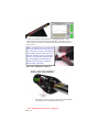
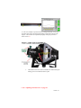
User Manual
Document #PROD-Basic-Mnual-04, Rev. C
GolfAchiever Basic Software Version 2.00 & above
Date: 12/15/2009
Focaltron Corporation
830-A East Evelyn Avenue
Sunnyvale, CA 94086 USA
Phone: (408) 530-8588 Fax: (408) 530-8062
www.golfachiever.com
PAGE 1
Getting Started
Introduction
Thank you for choosing GolfAchiever II® the ultimate golf analyzer.
With laser sharp precision, this break-through technology measures all
of the important golf swing parameters and displays the feedback
instantaneously.
To ensure that you obtain the highest accuracy and trouble-free
operation, it is important to read the User Manual and Quick Set Up
Guide prior to using GolfAchiever. Be sure to retain these documents
as your convenient GolfAchiever information source.
Please take a moment now to complete the enclosed Warranty
Registration Card and mail it to Focaltron.
System Requirements
GolfAchiever II is designed to work with a personal computer that
conforms to the following standards:
•
Operating System: Windows XP, & Vista
•
CPU: Intel Pentium 4 1.2 Ghz
•
RAM: 512MB (XP) 1GB (Vista)
•
Hard Drive: 200 MB of available hard disk space
•
Video: Video resolution of at least 800x600 pixels with at least
256 colors
•
Ports: One available serial (RS-232) interface, D- SUB 9-pin
connector
Power Requirements
A wall-mount power adapter is provided. This adapter plugs into a wall
socket that supplies USA-standard power (120 VAC @ 60 Hz.). If you
are in a country that uses a different power standard, you will need a
converter.
GolfAchiever II may be powered by a battery. A 9-volt lead-acid leakproof battery capable of delivering 0.5 amps is preferred. Other types
of batteries (or direct-current sources) may be used so long as the
voltage is within the range of 6 volts to 12 volts. Power cables for
attaching GolfAchiever to a battery are not provided.
Focaltron offers a complete battery system (battery, cabling, and
charger) for $295. Call your Focaltron salesperson for details.
PAGE 2
Safety Instructions
Read all of these instructions carefully. Save these instructions for later
use.
•
Follow all warnings and instructions marked on the product.
•
Unplug the power adapter from the wall outlet before attaching or
detaching any cables to the unit.
•
Unplug the power adapter before cleaning GolfAchiever II. To
clean GolfAchiever II, use only a damp cloth: do not use liquid
cleaners or aerosol cleaners.
•
Only plug the power adapter into an outlet that conforms to the
type of power indicated on the marking label. If you are not sure
of the type of power available, consult your local power company
or dealer.
•
Use only power adapters that provide low voltage direct current in
accordance with the specifications for the unit.
•
If an extension cord is used with this product, make sure that the
total ampere rating of the equipment plugged into the extension
cord does not exceed the extension cord’s ampere rating. Also,
make sure that the total rating of all products plugged into the wall
outlet does not exceed the fuse rating.
•
Do not allow anything to rest on the power cords or serial cord.
Do not place the cords where people may walk on them.
•
Do not place the product on an unstable cart, stand, or table. The
product may fall causing serious damage to the product.
•
Other than adjusting the alignment of the lasers as described in
this manual, do not attempt to service this product yourself.
Opening or removing covers may expose you to dangerous voltage
points or other risks. Refer all servicing to properly trained and
qualified service personal.
•
Do not look directly into the laser.
•
The following labels are attached to the GolfAchieverII L-Frame
in accordance with FDA regulations:
PAGE 3
FCC Information: The Federal Communications Commission Radio
Frequency Interference Statement includes the following paragraph:
This equipment has been tested and found to comply with the limits for a Class
A digital device, pursuant to Part 15 of the FCC Rules. These limits are
designed to provide reasonable protection against harmful interference when
the equipment is operated in a commercial environment. This equipment
generates, uses and can radiate radio frequency energy and, if not installed
and used in accordance with the instruction manual, may cause harmful
interference to radio communications. Operation of this equipment in a
residential area is likely to cause harmful interference in which case the user
will be required to correct the interference at his own expense.
If this equipment does cause harmful interference to radio or television
reception, which can be determined by turning the equipment off and on, the
user is encouraged to try to correct the interference by one or more of the
following measures:
• Reorient the receiving antenna.
• Increase the separation between the equipment and receiver.
• Connect the equipment into an outlet on a circuit different from that to
which the receiver is connected.
The user should not modify or change this equipment without written approval
from Focaltron Corporation. Modification could void authority to use this
equipment.
Disclaimer: Focaltron Corporation makes no representations or warranties,
either expressed or implied, with respect to the contents hereof and specifically
disclaims any warranties, merchantability or fitness for any particular purpose.
Further, this company reserves the right to revise this publication and to make
changes from time to time in the contents hereof without obligation of this
company to notify any person of such a revision.
Copyright © 1999, 2000, 2001, and 2002 by Focaltron Corporation. All rights
reserved. No part of this publication may be reproduced, transmitted,
transcribed, stored in a retrieval system or translated into any language, in any
form or by any means, electronic, mechanical, magnetic, optical, chemical,
manual or otherwise, without the prior written permission of Focaltron
Corporation.
GolfAchiever and Achiever are registered trademarks of Focaltron Corporation.
GolfAchiever is protected by patents and patents pending in the USA and
abroad.
PAGE 4
Table of Contents
Getting Started
Introduction
System Requirements
Safety Instructions
Care and Handling
Hardware Assembly and Setup
4
4
4
5
6
7
Unpacking GolfAchiever
Picking a Place to Play
Setting Up GolfAchiever
7
8
8
Installing the GolfAchiever Software
10
Creating a Shortcut to Achiever
Starting the Achiever Software
The Basics
Indoor Mode
Outdoor Mode
10
11
11
12
12
Creating and Editing a Player Profile
15
Overview
Creating a New Player
Selecting Clubs
Deleting a Player
15
15
16
17
Taking a Swing
Creating a Results Data File
Setting up the Playing Conditions
Set Physical Parameters—Advanced
Taking a Swing
18
18
19
19
23
Analyzing Swings
24
Printing Last Ten Shots Reports
Opening Raw Data and Results Data Files
Troubleshooting
26
26
27
Appendix I: Viewing Raw Shot Data
30
Appendix II: Diagnostics
33
Appendix III: Maintenance—LASER TUNING
35
Declaration of Conformity
45
PAGE 5
Care and Handling
This equipment uses lasers and other precision electronic and optical
parts. To avoid malfunction or alignment problems:
•
Do not drop the frame or subject it to mechanical shocks.
•
Do not stress or apply pressure to the frame in a manner that
would tend to bend the frame.
•
When taking a swing, do not hit the metal frame with the club
•
Do not step on the frame.
•
Do not stand the frame in water.
•
Keep the red plastic strips clean. A soft cloth and plastic cleaner is
recommended.
PAGE 6
Hardware Assembly and Setup
Unpacking GolfAchiever II
Your GolfAchiever II package should contain the following parts, as
shown below:
1.
2.
3.
4.
5.
6.
7.
8.
9.
10.
11.
12.
One GolfAchiever II L-Frame
One mat locater
One black rubber mat
One piece of artificial turf
One triangular leg (some assembly required)
One power adapter
One serial cable
Software (CD)
Five rubber tees: yellow, blue, white, red, and green
User Manual
One allen (Laser Tuning) wrenches
GolfAchiever II Warranty (not shown)
If any parts are missing or appear damaged, please contact Focaltron
immediately.
IMPORTANT!: KEEP your GolfAchiever packaging and shipping
box in a safe place. The box is required for safe handling of the
GolfAchiever system during shipment. If you ever need to send your
GolfAchiever back to Focaltron for repairs, you will need the box.
PAGE 7
Picking a Place to Use GolfAchiever II
GolfAchiever was designed to be a portable device, so you can move it
to different locations with minimum effort. For the location, pick a flat
level spot as the hardware and software have been optimized to show
the ball’s flight from a flat level field. GolfAchiever will work if tilted,
but the results may vary.
The location should provide a firm footing for the L-Frame. A soft spot
such as artificial turf or a carpet that has padding or long tufts may
allow the frame to twist when anchored to the ground and to move
when you take a divot. Such movement can cause problems with
GolfAchiever’s ability to record a swing or provide accurate results.
GolfAchiever works in most lighting conditions, both indoors and
outdoors. However, bright sunlight that shines directly into the red
plastic strips on the L-Frame (where the photodetectors are located) can
interfere with operation. Repositioning the L-Frame to face away from
the sun or shading the detectors from the sun will correct the problem.
Since GolfAchiever measures all the charactersitics of ball and club
just after impact, you can hit golf balls onto a range or into a net and
the GolfAchiever results will be the same.
Setting Up GolfAchiever II (see Quick Set Up Guide)
Once you have picked a location, you are ready to setup the
GolfAchiever II hardware. Follow these easy steps (NOTE:
Normally you will ignore steps #1 and #2 and START with Step #3):
1. Assemble GolfAchiever II Triangle Leg Clamp (First Use Only):
You will need pliers to attach the Triangle Leg Clamp to the
Triangle Leg. Do not over tighten the bolt into the clamp.
2. Anchor Base Holder to ground (optional): Hitting the turf or mat
with a club (“taking a divot”) may move GolfAchiever II so that it
is no longer aimed at a target. You can prevent this by attaching
the unit to the ground or floor. Pass large nails or screws through
the 1/4" holes in each D-Holder in the Mat Locator to attach
GolfAchiever to the ground. Do not tighten the nails or screws too
firmly - allow the Mat Holder to float up and down by a small
amount. Please note aiming GolfAchiever II instructions below.
3. Place Any Tee Through Bottom of Black Rubber Mat: Pick
the tee you will use and be sure that the bottom of the tee sits flush
with the bottom of the Black Mat.
4. Attach Rubber Mat to Base Holder: Be sure that the mat fits
snug in the D-Holders at the top of the mat.
5. Aim Base Holder-Rubber Mat Combination at Target: Aim
GolfAchiever at the intended target. To aim GolfAchiever; sight
along an imaginary line from the center of the tee perpendicular to
the Front of the Base Holder when connected to the Rubber Mat.
6. Attach Triangle Leg to L-Frame: Determine if you will be using
GolfAchiever II in right or left handed mode. Place triangle leg
under the arm of the side you will use. Be sure the front of the
triangle leg fits nicely into its slot near the elbow, while the clamp
clicks into place at the top of the L-Frame arm.
PAGE 8
7.
Set L-Frame into Front Slot on Base Holder: Be sure the
Azimuth pin in the middle front of the L-Frame Base sits in the
Azimuth Locator slot in the Mat Locator.
8.
Add Turf: Place the Turf into its tray in the Mat. The Turf is not
fastened to the mat and is allowed to “float” so that it can adsorb
the mechanical shock of the club hitting the turf.
9.
Connect GolfAchiever to Your Computer: Plug the serial cable
into the 9-pin connector on the L-Frame. Plug the other end of the
cable into the serial port on your computer.
10. Connect Power: Plug one end of the power adapter into the round
power connector on the L-Frame. Plug the other end into a power
outlet (120 VAC, 60 Hz, standard in the USA). The indicator in
the oval on top of the L-Frame should light with a combination of
yellow and green for a second and then change to yellow.
11. Start GolfAchiever software on your computer: Be sure that
you have selected the correct Right or Left-Handed Icon in the
upper right of your screen to match the swing you are analyzing.
Default setting is Right-Handed Mode.
IMPORTANT! - Changing Tees
During Use: To prevent breaking
the mat locator when changing tees,
use one foot to stand on the
GolfAchiever II hitting mat close to
the frame (base) to prevent
movement or separation of the mat
from the mat-holders and
GolfAchieverII L-Frame. After
positioning your foot, curl the back of the mat upwards to expose
the underside of tee currently in use. To remove the tee, first push
down on top of the tee and then reach under the mat to pull the tee
out from the bottom. Insert the new tee from underneath the mat.
Be absolutely sure to keep your foot in position on the front of the
mat during this entire process. HINT: If it becomes difficult to
insert and remove tees from the Rubber Mat, spray a small
amount of silicon spray around the inner wall of the mat hole in
the Rubber Mat.
Switching GolfAchiever II From Right- to Left-Handed Operation
When the need arises to switch from Right Handed Operation to LeftHanded Operation (or vice-versa), simply unattach the triangle leg, flip
over the system (be careful of the serial and power cables), attach the
triangle leg to the new side, carefully place the newly oriented
GolfAchiever II frame into its place on the mat locator (again paying
attention to the Azimuth Locator and slot in the mat locator), check to
be sure the cabling is out of the way, and select the Hand Option on the
top right of the GolfAchiever software screen to match the new position
of GolfAchiever II. See GolfAchiever II Quick Set Up Guide for
images and additional instructions on Changing Over L-Frame.
PAGE 9
GolfAchiever Software
Installing GolfAchiever Software
Before you install the GolfAchiever software, make sure your computer
meets the system requirements as listed on page 4.
Follow these steps to set up the GolfAchiever software from the
installation CD:
1.
Exit all programs to prevent conflicts with the Installation
Software
2.
Insert the GolfAchiever Software CD into the CD drive.
3.
If the Installation Program does not automatically start upon
inserting the CD, Click the Windows Start button and select RUN.
Type “d:\setup.exe” and then press enter. Replace “d:” with your
CD drive letter if different.
4.
Follow the on-screen instructions to finish installing the
GolfAchiever software.
Uninstalling GolfAchiever Software
1.
2.
3.
4.
5.
PAGE 10
Navigate to your Windows Start Menu and click on
Control Panel.
For Windows XP users click on Add/Remove Programs. For Windows Vista users click on
Programs and Features.
In the window that opens scroll down the list of
Programs until you locate the line titled
GolfAchiever BASIC followed by a version number.
Double click this line to begin the uninstall process.
Follow prompts to complete uninstall.
Starting the GolfAchiever Software
Before starting the GolfAchiever software, make sure the L- Frame is
plugged in and connected to your computer with the included serial
cable and power adapter.
Double click on the GA Basic icon found on your Desktop to start the
program.
Alternatively:
To start GolfAchiever Software, click on the Windows Start button and
select Programs>Focaltron>GA-Basic>GolfAchiever Basic.
You will also see an icon for the diagnostic program that was installed
with GolfAchiever. This can be used to recalibrate the sensors or to
help if the lasers need to be realigned. Instructions for the Diagnostics
program are included in Appendix II.
GolfAchiever Software Basics—Start Screen
After starting GolfAchiever software, you will be taken to
GolfAchiever’s start up screen (below). GolfAchiever software has
two operating modes — Indoor and Outdoor. You will need to select
between these modes depending upon your environment. If you are
hitting outdoors, select OUTDOOR mode. If you are hitting into a net
indoors, select INDOOR mode. Simply click to on your mode to begin.
PAGE 11
Indoor Mode
Indoor mode should be selected from the GolfAchiever Start Screen
when you will be using GolfAchiever indoors (into a hitting cage or
net). Indoor Mode offers the following three software screens:
Indoor Mode’s
Down Range
(top left) and
Analysis screens
(bottom left)
show you
different
graphical
representations
of each shot.
The data screen
(right) displays
swing analysis
information in
data only format.
Use the toggle
button at the top
right of any
screen to switch
screens.
Outdoor Mode
Outdoor Mode should be selected from the GolfAchiever Start Screen
when the GolfAchiever system will be used outdoors (outdoor targets).
Ball Flight has been eliminated from the Outdoor Mode screens to
avoid confusion between actual and simulated ball flight. Outdoor
Mode offers the following two screens:
Outdoor Mode’s
Analysis Screen
(left) graphically
reports Swing
Path, Face Angle,
Azimuth, Launch
Angle, and
Distance Carried,
while statistical
data is also
provided.
The Data Screen
(right) is also
available in
Outdoor Mode.
PAGE 12
Set-Up Screen
Before taking a shot, you will need to use the Setup screen to create a
player profile. A player profile includes information such as the
golfer’s name, height, and the (customized) clubs the golfer may use.
This information is essential to Achiever so that it can return the most
accurate results.
Use the Setup
screen to enter
player name
and choose
which clubs
are available
to each player.
Getting to Know the Buttons
Button
Description
Screen Selection Buttons: Switch/Toggle between the Down
-Range, Analysis, and Data Screens. The Switch/Toggle
Button appears in the top right of the software screens. The
icon displayed depends on the current screen you are using.
Setup: Opens the Setup screen. This button is disabled while
in the Play Mode.
Right or Left-Handed Operation: Be sure that the icon on
the screen matches the GolfAchiever II’s current set-up.
Play: Use this button when you are ready to take a shot. This
button has four modes: gray if the software is unable to locate
the hardware, orange when it is in standby mode, green when
it is ready for you to take a swing, flashing yellow while it is
resetting from some thing breaking the laser grid (you will
usually see this after placing the ball on the tee).
Clear Stats: Clears the statistics box of the Down Range
screen.
Mulligan: <ALT + CLEAR STATS> removes the last shot
from the statistics (Down Range Screen) and Printout.
Clear Path: Clears the traces of the ball’s flight path(s).
PAGE 13
Button
Description
Select Player: Select any of the players that have been entered
through the Setup screen.
Select Pin Distance: Select from the list of distances from tee
to the pin (the flag stick is located in the center of the green).
Select Club: Tell Achiever which club you are about to use.
Only clubs in the current player’s bag will be listed. To add/
remove/customize clubs from a player’s bag, go to Set Up
Screen (Customize Clubs).
Select Ball: Select the type of ball you are using: Wound, 2Piece, or Foam.
Select Tee Height: Select the height of the tee you are using.
Set Environment: Set environmental factors, including wind
speed and direction, grass conditions (wet or dry), temperature,
and elevation. The higher the elevation, the further the
simulated ball flight.
Open File: Opens a saved data file — results data (.gsd) or raw
data (.gdb).
Save File: Can be used to save a Raw Data File or to create a
shot log of Results Data (see page 20). NOTE: Environmental
data is not saved.
Print: Prints GolfAchiever’s Last Ten Shots Statistical Report
providing detailed per shot and averaged data for up to the last
10 shots.
Print Preview: Press <ALT + PRINT icon> to send a Last Ten
Shots Report to the Screen.
Information: Shows Achiever software version.
From the Analysis screen, press <ALT + ? icon> to view raw
shot data instead of overhead view (see the Appendix I).
Exit: Closes the GolfAchiever program.
Moving Around the Screens and Buttons
Like most Windows programs, you can use your mouse or your
keyboard (or a combination) to access the different features of
GolfAchiever. To use your mouse, just point and click on the buttons or
options you want. To use your keyboard, press the <TAB> key to
highlight different buttons or options and press enter to select the item.
Hold down the <SHIFT> key while you press <TAB> to select items
in reverse order.
PAGE 14
Creating and Editing a Player Profile
Overview
Before taking a swing, you should use the Setup screen to setup a
player profile. A player profile includes information such as the
golfer’s name, height, stance, and the clubs the golfer will use. Also use
the Setup screen to edit an existing player profile or to change device
settings such as the available tee heights.
Creating a New Player
1.
Click on the Setup button to open the Setup screen.
2.
Click on the Player Setup button to open the Player Setup
dialog.
3.
Select the New Player checkbox and type a name for the player
into the Name box.
Enter the height of the player.
Choose the player’s default club set: men’s or women’s. Club
selection only provides a starting point for GolfAchiever. If the
player has clubs that are different than a standard set, you can
further customize these clubs later (see Page 16-17).
Click Add Player to close the dialog and add the new player to
GolfAchiever’s player list.
4.
5.
6.
PAGE 15
Selecting Clubs
When you create or edit a player profile, you can choose which clubs
are available to the player by adding and removing clubs from the
player’s bag in the Setup screen.
Adding Clubs to a Player’s Bag
1.
In the Setup screen, select the player from the Player’s Name list.
2.
From the Club Shop list, click on the club you want to add. Note
that several of the club’s statistics are displayed to the right of the
Player’s Bag list. If you want, you can customize the
specifications for the club.
3.
Click the Add button to add it to the Player’s Bag.
Customizing a Club
1.
In the Setup screen, select the player from the Player’s Name list.
2.
In either the Club Shop list or Player’s bag, click on the name of
the club you want to customize.
3.
Click the Customize button to open the Club Customization
screen. Two important GolfAchiever Custom Club variables,
Club Factor and Gear Effect, are discussed below:
CLUB FACTOR— Designed to help the GolfAchiever determine the
center of gravity on the clubhead as it is swung, club factor is a relative
number with a range of –2 to +6, and a default setting of 2.1 for Driver
and 1.5 for all other clubs. The general rule to effectively use club
factor is that if the GolfAchiever simulation shows too much hook, you
need to lower the club factor. Conversely, if the GolfAchiever
simulation shows too much slice, you need to raise the number.
GEAR EFFECT— Determined to help the GolfAchiever understand
each persons relative Gear Effect when the club is swung and the ball is
struck on the toe or heel. A relative number with a range of –100 to
+2000, and a default setting of 800, the gear effect should be higher
with stronger swings and lower with softer swings.
PAGE 16
4.
Enter the custom specifications into this dialog and click OK to
accept the new settings. These settings will apply to the club
shown in both the Club Shop and in the player’s bag. It will not
affect the specifications of the club for any other players. If you
wish to add a description/name to the club, click NEW. This will
enable the Suffix box where you can enter the title of the club.
The limit is 12 characters. Here we’ve entered ‘GA-II.’
TIP: You may find it helpful to enter a company’s fitting cart as
a player name so that you may customize all of the 5 or 6-irons in
that cart and add them to the “player’s bag.” The same concept
can be used to list all of the drivers on your show floor that
people frequently request into a player’s bag named DEMO.
This will save time from having to create/complete a player bag
and customize clubs for each person that walks into your store
hoping to demo equipment .
Removing Clubs from a Player’s Bag
1.
In the Setup screen, select the player from the Player’s Name list.
2.
From the Player’s Bag list, click on the club you want to remove.
3.
Click the Remove button to remove it from the Player’s Bag list.
Clubs removed from a player’s bag remain in the Club Shop list for
later use. If you wish to remove a club from the Club Shop list,
highlight the club from the list and select customize. Select Remove
from the customize window to remove the club from the Club Shop.
Deleting a Player
1.
Click on the Setup button to open the Setup screen.
2.
Select the player from the Player’s Name list.
3.
Click the Player Setup button to open the Player Setup dialog.
4.
Click the Remove button. GolfAchiever will open the Remove
Player Name dialog to confirm that you want to remove the player
from the list.
5.
Click Yes in the Remove Player Name dialog to remove the player
from the list.
PAGE 17
Taking a Swing
Creating a Results Data (.gsd) File
The results data for all shots can be saved to a single “results” file (.gsd
extension) by turning on the save option prior to making the shots. See
page 24 for Viewing your Results Data Files.
1.
Pick a Player.
2.
Before hitting any shots, click on the Save Icon (left). The
GolfAchiever GSD/GDB File Save Setting Dialogue Box will
appear.
3.
Click the box for Save Swing Result Data to: and hit OK if you
accept the default filename and location (Player Name and Date).
You may change the filename in the text area and/or save the file
to a different location by hitting the Browse Button and selecting
new location.
4.
When you have the filename and location desired, click OK.
The data in this file is formatted in a way that can be easily imported
into spreadsheet or database programs.
The Results Data File feature only saves statistical data about the shots
taken; it does not save the raw data and cannot be read back into
GolfAchiever to display the shot later.
The GolfAchiever GSD/GDB File Save Setting Dialogue Box
(accessed through the Save Icon) also allows you to save Raw Data
Files (.gdb extension) for an individual shots after they are taken. For
instructions on saving .gbd files, turn to page 23. Select the Auto Save
box to automatically save data without having to manually click Save.
NOTE: Raw Data Files may be saved while Results Data Files are being
created.
5. The Database Save component is only available in conjunction with select software and/or versions. For normal use
with GA Basic this function will be grayed out.
PAGE 18
Setting up the Playing Conditions
If you are using tees that didn’t come with GolfAchiever, you will need
to set the new tee heights into GolfAchiever Software to ensure
accuracy. If you want to simulate different playing conditions, or if you
are hitting outdoors and you want to set GolfAchiever to the same
weather conditions, you can also input those variables before you start
hitting. You can adjust these and other variables through the Set
Advanced Physical Paramters and Set Environment Dialog Boxes.
Set Physical Parameters—Advanced
To access the Advanced Physical Parameters Dialog Box:
1.
Click on the Setup button to open the Setup screen.
2.
Click on Device Setup (GolfAchiever image in Upper Left) to
open the Set Physical Parameters box as shown below.
3.
From here you can adjust a number of variables that will be
discussed on the following pages.
PAGE 19
Startup Default Mode
The start page of GA Basic offers two operating modes: Outdoor and Indoor. For users who consistently choose one operating mode over the other, the Startup Default Mode will save
your desired selection for future uses.
For users that consistently use the Indoor mode, select Indoor.
Alternatively, for those that consistently use the Outdoor mode,
select Outdoor to save your selection for future uses.
Physical Setup Screen
The Physical Setup Screen function temporarily changes the
desktop resolution setting to 800 x 600, bringing the GA Basic
program to full screen size. After exiting the program, the desktop resolution is restored to its previous setting.
Tee Position Variables
Tee Height and Tee Location (Tee Back and Tee Side) are critical
factors in achieving the highest level of GolfAchiever accuracy. The
tee position settings greatly effect launch angle, ball speed, azimuth,
distance carried, and other variables. IMPORTANT!: Any errors in
measuring or entering Tee Position Variables will cause errors in
GolfAchiever reported data. Because precise Tee Position Variables
are a critical element to GolfAchiever accuracy, Focaltron
recommends that you use GolfAchiever golf mats, mat locators, turf,
and tees anytime you use GolfAchiever.
TEE HEIGHT—If you will not be using a tee provided by
Focaltron, be sure to enter your tee height information into the
Advanced Physical Parameters Dialog Box.
To enter the height values of Non-GolfAchiever tees:
1.
Under Tee Position, replace one of the original GolfAchiever tee
heights with your new tee heights. Be sure to use precision in
your measurement of the actual tee heights (example:
GolfAchiever’s blue tee is measured to 1/100th of an inch at 2.70”
tall).
2.
Click OK.
Enable Auto Tee Selection
Selects appropriate tee automatically depending on club being used.
PAGE 20
TEE BACK—This value represents the perpendicular distance in inches
from the edge of the GolfAchiever frame to the center of the tee. The
default position is 11.7”. You would adjust Tee Back if you were to
hit from the turf in front or in back of the tee position or if you integrate
your own mat design for GolfAchiever.
TEE SIDE—This value represents the distance left or right from the
center line in the green turf, with the center line being centered over
the tee, parallel to the target line. The default setting is 0”. A ball set
two inches closer to the post would have a Tee Side of +2.0”, while a
ball one inch closer to the player would have a Tee Side of –1.0”.
ENABLE AUTO TEE SELECTION— enables the software to
automatically select the tee height in relation to the selected club.
Physical Parameters
GolfAchiever’s ball flight dynamics are mainly defined by four
physical variables: Friction Coefficient, Magnus Coefficient,
Spin Time Constant, and K-Azimuth.
Friction Coefficient—The drag factor giving the distance of the
shot. It’s effect is more pronounced on Drivers and low irons
than on higher lofted clubs. NOTE: Friction Coefficient is the
only Coefficient that you can adjust. Lowering the Friction
Coefficient provides for more carry distance.
Magnus Coefficient (Magnus + Spin) - The lifting power of a
ball that makes it climb into the air. The lift factor is more
significant in forecasting the ball flight of lower lofted clubs.
Spin Time Constant—A spin rate assumption which is a function
of ball construction, momentum, and condition of the surface
variables.
K-Azimuth—Having its influence on side spin, the greater the KAzimuth variable, the more curvature of ball flight.
Display Units—English or Metric
Select your preference.
Save Advanced Physical Parameters
Click “Save these parameters for each time this program is run” if you
would like to Save and Keep Advanced Physical Parameters
Adjustments you have made. If you do not select this option,
GolfAchiever will revert back to default settings the next time the
program is run.
PAGE 21
Theme Selection
This pull down menu allows the user to select from four different background themes when playing in the downrange screen mode. You can
also change themes directly from the downrange screen mode.
To do this right click the icon shown to the left and select the desired
theme.
Setting Weather Conditions
You can use GolfAchiever’s environment controls to simulate different
weather conditions.
1.
Click on the Set Environment button to bring up a dialog for
entering weather conditions.
2.
Enter the wind speed and direction by either clicking on the wind
vector graph or by typing in the values.
3.
Select the ground condition by clicking and dragging the control
between “wet” and “dry.” This setting would effect the ball’s
bounce and roll (bounce and roll can be turned on or off through
the Advanced Setup screen). NOTE: Bounce and Roll is not an
active feature in the current Ex. version of GolfAchiever software.
4.
Enter values for elevation, and temperature. These will affect the
ball’s trajectory and distance.
GolfAchiever Measurement Range
Launch Angle—2 degrees to 65 degrees
Azimuth—- Closed 30 degrees to Open 30 degrees
Ball Speed—5 MPH—250 MPH
Swing Path—Outside In 20 Degrees to Inside Out 20 degrees
PAGE 22
Setting Up the Shot
1.
Select a Player: Click on the Player button and select a player
name from the list. To add a new player to the list, use the Setup
screen. Note: You cannot change the player while GolfAchiever is
in Play mode and the Play button is green. Click the Play button
to switch GolfAchiever to Wait mode (the Play button will turn
orange) before changing players.
2.
Select the Dinstance to the Pin: Click on the Flag button to set
the yardage from the tee to the pin. (Default is 150 Yards).
3.
Select a Club: Click on the Golf Bag button and select a club
from the list. To add or remove clubs from the player’s bag, use
the Setup screen.
4.
Select a Ball Type: Click on the Golf Ball button and select the
type of ball you are going to hit: Two-Piece (Default selection),
Wound, or Multi-Layer.
5.
Select a Tee Height: Click on the Tee button and select a tee
height: ‘Grass/Green’ (even with the turf), ‘Low/Red,’ ‘Mid/
White,’ ‘High/Blue’ (Default Selection), and ‘X-High/Yellow.’ If
you are using a different tee, you can use the Setup screen to
adjust the tee height (see Page 19).
Taking a Swing
1.
Enter the Play mode: Click on the large orange Play button to
enter the Play mode. The button on the screen and the LED (light)
on the L-Frame should both change to green.
2.
Place the ball on the tee: A hand passing through the laser grid
or a player’s waggle may cause the indicator to temporarily switch
to yellow and the Play button to flash the “Wait” signal; this is
normal. GolfAchiever will re-arm before the player hits the ball.
3.
Take a swing: Take your normal swing at the ball. Both the ball
and the club-head must pass through the laser grid for a shot to
register. Once a shot is registered, the GolfAchiever program will
measure and calculate the ball trajectory and display it in near real
time. At the end of GolfAchiever’s ball flight simulation, the shot
data will be displayed on all of the GolfAchiever screens.
4.
Save Shot Raw Data (Optional): The raw data from any shot can
be saved immediately following the shot, before anything else
crosses the laser grid, by clicking on the Save button at the lower
right of the screen. The Save Dialog Box will appear. Select
save RAW DATA (.gdb) file option and save the file. This shot
file can be played back at a later time. Note that the Player name,
Club, Ball Type, and Tee Height are saved with RAW DATA
files, but environmental conditions are not saved.
5.
Take the Next Swing: You can repeat these steps to take as many
swings as you like. If the ball flight paths begin to clutter up the
screen, you can remove them by clicking the Clear Path button.
To reset the statistical data, click the Clear Stats button.
PAGE 23
Analyzing Swings
Down Range Screen (Indoor Mode Only)
The Down Range screen represents a virtual driving range having its
perspective from a point directly behind the tee. “Last Shot” data and
“Statistical” data is displayed on this screen, as well as a trace of the
ball’s simulated flight path.
The displayed height of the ball flight paths are approximately one
fourth of the actual height of the calculated flight paths in order to keep
most shot paths on the screen.
Last Shot Data
The last shot data includes the player, club, clubhead speed, distance,
launch angle, ball speed, club speed, and swing path.
Statistics
The Down Range screen’s shot statistics show the statistical averages
and standard deviations of the different parameters. These values are
reset when the player or club is changed, or when the Clear Stats button
is clicked.
Analysis Screen (Indoor Mode)
The (Indoor) Analysis screens shows two different views of the shot—
overhead and side — and gives some more detailed shot data.
PAGE 24
Swing Path, Azimuth, Club Face, and Launch Angle
These three graphics demonstrate the respective angular measurements
as calculated from the most recent shot. The information for the
current shot appears just after the ball flight simulation has ended.
Specifications and Shot Data
This screen shows all the specifications and resulting data about the
shot. This includes the player’s name, the club, the ball, the tee height
and the resulting measurements of club and ball speed, distance, offline distance, distance to pin, maximum height, flight time, and face
impact. Please note the best results will be obtained only when using a
real golf ball (vs. cayman, foam, etc.).
Analysis Screen (Outdoor Mode)
The Analysis Screen for Outdoor Mode is a modification to the
Analysis Screen for Indoor Mode. The modifcation is that the
overhead view is replaced with Statistical Averages of Player
Performance.
Data Screen (Indoor and Outdoor Mode)
GolfAchiever’s Data Screen is used for Indoor and Outdoor Mode.
The Data Screen only presents statistical data on Ball Speed, Club
Speed, Launch Angle, Azimuth, and Distance Carried.
PAGE 25
Printing Last Ten Shots Reports
A Last Ten Shots Data Screen can be printed by hitting the Print
button in the lower right of the screen. A more comprehensive Last Ten
Shots report (as shown below) is available if you hit <ALT + Print>.
You can print the comprehensive report by hitting the PRINT button at
the bottom right of this screen.
Opening RAW DATA and RESULTS DATA files
If you wish to view a saved RAW DATA shot file or a RESULTS
DATA FILE, click on the Open Folder button in the lower right of the
GolfAchiever software screen. If you open a RAW DATA (.gdb) file,
the saved shot will be played back on your computer using the current
Environmental Conditions. If you open a RESULTS DATA (.gsd)
FILE, the following image will appear on your screen. At this time,
you cannot print .gsd files from GolfAchiever Software. However, the
Results Data file can also be opened as a delimited text file in MS
Excel for further analysis.
Exiting GolfAchiever
To exit the GolfAchiever software, click on the Exit button in the lower
-right corner of the screen.
PAGE 26
Troubleshooting
A “Check Frame” Message appears when starting
GolfAchiever
When the program starts it searches the serial ports for the
GolfAchiever hardware. If the program finds the GolfAchiever
hardware it performs a simple hardware test to ensure proper operation.
If the L-Frame’s sensor thresholds are out of adjustment or if
something is blocking one or more sensors, this test will fail and the
following “Check Frame” message will appear:
1.
Check that nothing is blocking any part of the red plastic strips on
the L-Frame (these strips cover the photodetectors).
2.
Wipe the strips with a clean soft cloth.
3.
Click Retry to retry the test. If it passes the second test, it will
start the software. If it fails, the following window will open
allowing you to recalibrate the sensors:
4.
Click Yes to recalibrate the
sensors.
If after recalibrating the sensor thresholds, erratic behavior occurs
with continual false triggers or with many seemingly good shots
resulting in Wait/Error indications, it may be necessary to exit the
GolfAchiever program and run the Diagnostic program. The
Diagnostic program may show that mechanical re-alignment of the
lasers is required. Refer to Appendicies II and III for directions.
PAGE 27
The Play button is gray and you cannot enter Play mode.
When the GolfAchiever program is started it searches for the L-frame
and tests it. If GolfAchiever cannot communicate with the L-frame, the
Play icon is turned gray and play mode is not permitted.
•
Check the LED indicator on the L-Frame. If it is not on, the frame
is not receiving power. Check that the power adapter is firmly
plugged into the unit and that the adapter is plugged into an active
power source (120 volts at 60 Hz). Then exit and restart the
GolfAchiever program.
•
Check that one end of the serial cable is connected to an active
serial port on the computer and that the other end is connected to
the L-Frame. Then exit and restart the GolfAchiever program.
•
Check that the serial port on the computer is functioning properly.
Connect another device to the computer’s serial port and confirm
that it functions as expected. If another device is set up to use the
same serial port, change that device’s settings to a different port or
exit the program before starting GolfAchiever. In many cases, a
program such as “Palm Pilot” has control of the system’s serial
port, which does not allow the system to recognize the
GolfAchiever hardware. To remedy this, simply exit Palm Pilot.
Other Buttons are Gray and Unavailable
When you are in Play mode, several features are unavailable and their
buttons are grayed out. Features that are unavailable in play mode
include: opening the Setup screen, changing the player, and opening a
saved shot.
Shots are not Displayed
Occasionally GolfAchiever cannot display a shot. This often happens
with a bad shot such as topping the ball. The problem is often generated
by the ball and the club going through the detection zone at the same
time. When this happens, GolfAchiever cannot tell the ball from the
club and the play button will briefly blink yellow. Please review
Appendix I on viewing raw shot data for examples of shots that
GolfAchiever may not be able to display GolfAchiever may not be able
to display. Additional reasons GolfAchiever may fail to display a
swing include the following:
•
Remove any objects that may be in the detection zone, interfering
with the lasers’ beams or the red plastic lenses.
•
Clean the red plastic lenses with a soft cloth and plastic cleaner.
•
Make sure that the frame is on a flat surface and the two rubber
feet under the frame and the rubber foot under the triangle leg is
touching the ground.
PAGE 28
•
Physically adjust the lasers so that their red beam of light
illuminates all the photodetectors located behind the red plastic
lenses. Refer to the “Aligning the Lasers” section of Appendix III
for directions.
The ball did not land where GolfAchiever indicated
GolfAchiever’s default setting is to simulate carry distance only.
GolfAchiever’s bounce and roll setting can be enabled in the system set
-up screen. If you find that you have problems with the distance carry
reported by GolfAchiever, please check the following:
•
Check that the height of the tee set in GolfAchiever matches the
height of the tee installed in the mat.
•
Check that the “Tee Back” in the Set Physical Parameters Advanced window is set to 11.7 when you are hitting off the
normal tee position.
•
Check that the Tee Side is set to 0 when you are hitting off the
normal tee position.
•
Check that the frame sits on a level surface and is aimed at your
target.
•
GolfAchiever is designed to operate on a level field. Hitting to a
hill will yield a difference between the actual ball landing position
and what GolfAchiever displays.
PAGE 29
Appendix I: Viewing Raw Shot Data
You can view a graphical representation of the raw shot data (the raw
data does not include information such as the tee heights or weather
conditions). While in the Analysis screen, hold down the <ALT> key
and click on the Information button (?): the overhead view of the shot
will change to show the raw data:
The
Vertical axis is time, the left half of the image shows data from the post
sensors and the right half represents the base sensors. For most shots,
you should be able to discern the ball from the club shaft and head (the
club will appear upside down). Hold down the <ALT> key and click on
the Information button again to return to the normal view.
Examples:
A: The left side of the club shaft image is missing two data
points from blocked or faulty sensors. The missing data
results in a swing path calculated as minus 170 degrees.
B: This is a great shot with only one problem—there is no
ball. Because of a sensor error, there is an abnormal break in
the right-side image of the club shaft. The program acts as if
the separated part of the right image is a ball. From this
segment, it calculates the ball speed as 137 m.p.h. and
proceeds with the simulation.
PAGE 30
C:
Probably caused by a very slow swing or a low- angle shot,
the right image of the ball is merged with the club face.
GolfAchiever is able to calculate the ball speed from the left
half of the image but, since the ball’s position is calculated
using both sides, some error is introduced and the shot
reading will not be as accurate.
D:
Probably caused by a high take-off angle or a slow follow
through, GolfAchiever is unable to separate the ball from the
club head. GolfAchiever will indicate an error (the Play
button will flash on the screen); it will not display a
simulation or shot data.
E:
The club head crossed the sensors way before the ball.
Probably caused by topping the ball.
F:
Another example resulting from a topped ball. Unfortunately
this shot will not result in an error indication even though the
ball speed will be incorrect (191 m.p.h. in this example)
because the ball “length” is truncated on both sides by the
image of the club. If the displayed shot is significantly longer
than the actual shot, this is probably what occurred.
G:
An example of “noise” interfering with the reading of the
shot, probably created by the club hitting the mat after ball
impact. GolfAchiever can ignore noise that is on only one
side of the data, but the problem here is that the lower set of
noise occurs as the ball is being sensed, effectively increasing
the size of the ball to the point where GolfAchiever rejects it,
resulting in an error indication.
PAGE 31
PAGE 32
H.
This is an example of noise that starts before either the club
or ball starts going through the laser grid. The club probably
hit the turf way before contacting the ball. the resulting early
noise is ignored since there is no matching object on the right
side of the image. However, since the ball and club are
delayed until the slower part of the graph there is significant
loss in accuracy.
I.
This shows noise patterns resulting from strong hits to the
turf, resulting in an error indication.
J.
In this shot the ball is hit by the tip of the club and driven into
the post, causing ringing in the base and post laser. This shot
results in an error since no ball was sensed by the base
sensors (the noise at the top is “too big” to be sensed as a
ball).
K.
Sunlight has caused blockage to some detectors represented
on the right half of the raw data screen (hole between shaft
and club-head). Mistakenly, this shot will be reported as
having an inside out path of more than 12 degrees. This will
also cause problems in the GolfAchiever’s ability to
accurately predict shot shape. To ensure accurate results, be
sure that the sun is not overpowering the lasers and saturating
any of the GolfAchiever’s photo detectors, such as in this
problem case.
Appendix II: Diagnostics
Running the Diagnostic Program
1.
Verify that GolfAchiever hardware is connected and powered up.
2.
Open the Windows Start menu and select
Programs>Achiever>Diagnostics to start GolfAchiever’s
Diagnostics program (or double-click on the Diagnostics icon
from your system desktop if you created a shortcut for
Diagnostics):
3.
Click on the “Comm Port” list box on the upper right of the
window and select the comm port that is connected to the LFrame. If the program finds the GolfAchiever device, the serial
number of that device is listed in the text box at the bottom of the
Diagnostics window.
The Main Graph
At the top of the window, select either Post or Base, and then click the
Refresh button to show a bar graph of the 32 device sensors, either the
base sensors or the post sensors, depending on your selection:
The height of each bar represents the signal size on that channel .
PAGE 33
Although the value of the main graph goes from zero on the bottom to 127 (7F
hex) on top, an average comparitor circuit within each device actually saturates at
about 77. GolfAchiever needs a device setting of at least 40 on each sensor/bar
to work properly. You may click on any bar to display its value in the box at the
bottom of the window.
The Real Time Indicators
These indicators are along the bottom and to the right of the main graph. They are
numbered to correspond with the actual sensor designators. After selecting a
comm-port or after refreshing the main graph these are either blue (off) or yellow
(on) depending on whether or not their signal strength is above or below their
corresponding threshold.
The main use of the Real Time Indicators is in the Real- Time mode or the
Alternate Real-Time mode as explained below.
The Buttons
Available buttons are green. When a button is inactive and cannot be selected, it
is grayed out.
Refresh Graph: Clicking on this button starts a sequence of commands to the
GolfAchiever device that determines the signal strength of each of the 64 sensors.
During this sequence the other buttons are not active. Note that after the
completion of this process both the Base and Post signal strengths will have been
determined.
Continuous: Setting this check box before clicking on the Refresh button puts
the device in a mode where it will continuously refresh the main graph. When
turning this mode off please remember that changes will only be registered
between each refresh.
Real Time: Click to enter the Real Time mode or hold down the Alt key and
click to enter the Alternate Real Time mode. Both modes allow an object (a hand
for example) to be run in front of the Base and Post sensors. In the standard mode
the obstruction will appear yellow but will become invisible if it stops moving. In
the Alternate mode the lasers are continually blinked so an obstruction, even if
stopped, will appear blue on a background of yellow.
Calibrate: Click here to reset the thresholds. The thresholds are set to 3/4 of the
minimum signal strength found in each group of eight sensors that use the same
threshold.
Print: Prints the value of the signal strength of all 64 sensors along with the date/
time. It also prints out the eight threshold values.
PAGE 34
Appendix III: Maintenance
GolfAchiever is designed to maintain working condition with a
minimum of attention. Keeping it dry and clean is the only requirement.
If the unit is physically abused, such as dropping it or hitting it with a
golf club, than additional adjustment may be required.
Check Frame Message
If the Check Frame window appears while starting the GolfAchiever
software, there may be an object in the laser’s path or the lens may be
dirty. First remove all objects, press the turf down into the rubber mat,
and clean the red plastic lenses using a soft cloth and plastic cleaner.
Then click Retry in the Check Frame window. If a second Check Frame
message appears, click on the Yes button to readjust the sensors’
thresholds. If the Check Frame window still shows errors, the lasers
may need adjustment.
Please be sure you have read and completely comprehend
Appendixes II and III prior to beginning the laser tuning process.
You may find it helpful to speak with a GolfAchiever customer
service representative prior to tuning a laser for your first time. If
you do not feel confident in tuning the lasers after reading
Appendixes II and III, the unit may be returned to the manufacturer,
packed in its original box, for service. A Return Materials
Authorization (RMA) must be obtained from the factory before
returning the unit.
Aligning the Lasers
GolfAchiever uses two lasers to illuminate a series of photodetectors.
Each laser produces a line of red light so that it may illuminate a line of
photodetectors. The lasers are housed at the ends of the L-Frame and
are accessible for adjustment by removing the protective covers with a
Number 1 Phillips screwdriver. The photodetectors are behind the red
plastic strips in the post and base of the L-Frame. The photodetectors
are not accessible.
Aligning the lasers consists of aiming the lasers so that their lines of
light illuminate all the photodetectors. This is best done in a dim room
so that the laser light is easily visible. The coarse alignment of each
laser is done by observing the position of the line of light and adjusting
the laser position so it is close to the center of the red plastic lens. As
the line of laser light begins to appear centered on the row of sensors,
you will then use the Diagnostic program, included with the
GolfAchiever software, to fine-tune the laser’s position.
Caution! While aligning the lasers do not let the laser
beam shine directly into your eyes.
PAGE 35
Tools
The following tools are required to align the lasers:
•
Number 1 Phillips screwdriver
•
A 7/64 ball-point hex key L-Wrench (Allen Wrench) - two
are included with your GolfAchiever Package
•
Computer with Diagnostic program (the diagnostic program
is automatically installed with the Achiever software)
Remove Covers
1.
Remove the plastic cover at the end of the L-Frame’s base by
unscrewing the three Phillips-head screws.
2.
Remove the plastic cover from the end of the L- Frame’s post by
unscrewing the two Phillips-head screws located in the plastic
cover.
Connect Unit
1.
Attach the serial cable to the L-Frame and to the computer
2.
Attach the power-supply to power up the L-Frame.
3.
Turn on the computer and start the test Diagnostic program (from
the Windows Start menu select Programs>Achiever>Diagnostics).
4. In the diagnostic program,
select the proper comm port
for the serial port connected to
the L- Frame. The buttons on
the computer’s screen should
turn green indicating that
communications have been
established.
Base-Laser Alignment
(Low Post Sensor Levels)*
1.
Turn the base-laser on by clicking on the Diagnostic program’s
Refresh Graph button. The laser will blink for a short time (less
than a minute), and then GolfAchiever will display a colored
graph representing the detected laser signal strength (See
Appendix II on page 29).
2.
Click on “Post” at the top of the screen to view the graph of the
Post detectors’ performance. Each colored bar represents a single
detector in the post, which is receiving the light from the base
laser. If the base-laser is misaligned, the result will be low values
(less than 40) for several detectors, and the graph will look similar
to one of the pictures on the following pages:
*Reminder: When improving the “Post” graph, adjustments must
be made to the base-laser.
PAGE 36
Below are a few examples of a misaligned base-laser with the corresponding
post graph readings:
A: This base-laser is misaligned near the top of the post. The picture shows
that the right side of the laser line (near the top) is below the lens of the unit
and needs to be rotated upwards. This would be accomplished by slightly
turning the base-laser rotation screws.*
B: The above photo shows a base-laser that is misaligned on both ends, registering on only a few of the middle detectors, as can be seen by the graph.
Adjusting the rotation screws of the base-laser will even the laser line back to
the center of the lens.*
C: This base-laser is aimed above the lens near the bottom, accurately creating a graph that shows the levels falling off at the bottom of the post. Again,
this can be corrected by adjusting the base-laser rotation screws.*
*See “Adjusting Rotation Screws” on page 38
PAGE 37
D: This is an example of a base-laser that is misaligned laterally. Notice
how the entire laser is above the sensors and needs to come down to be correctly aligned. This would be accomplished by slightly turning the base-laser
lateral screws.**
HINT: A helpful way to view where the
laser is in relation to the sensor strip is to
use a white piece of paper. Dimming the
room lights is still the easiest way to see
the laser, but when you are in a location
where it is not possible to dim the lights
(or when aligning your GolfAchiever
outdoors), having a piece of paper on
hand can help a great deal.
Base-Laser Alignment Continued...
3.
The Rotation Lock Screw (Silver) should not be altered during
the tunning process as it holdes the laser in place.
**See “Adjusting Lateral Screws” on page 38
PAGE 38
Adjusting Rotation Screws: The laser line rotates around a
central axis point in a circular manner — if the left side goes up the
right side will go down. When adjusting a laser’s rotation, it is
extremely important that you first loosen one Rotation screw and
then tighten the other. Repeat this procedure until the beam is
parallel with the red lens in the post. Finish by tightening up the
screws just enough so that they are snug and apply a small amount
of pressure on the bracket and the opposing screw. Do not overtighten as this warps the bracket and may result in stripping the
threads in the aluminum brackets or cracking the brackets.
Adjusting Lateral (up and down) Screws: Loosen one
Lateral screw and then tighten the other until the beam is in the
center of the red lens and reflections can be seen from all photodetectors. The screws should be tightened just enough so that they
are snug and apply pressure on the bracket and the opposing
screw.Do not over- tighten as this warps the bracket and may result
in stripping the threads in the aluminum brackets or cracking the
brackets.
5.
Repeat the previous steps until the beam appears to be well
positioned.
Click on Refresh Graph in the Diagnostic program. Wait for the laser to stop
blinking and for the button to turn green, indicating that the test is finished.
Observe the graph noting the value of the lowest detector. Repeat the baselaser alignment process until all the bars in the graph are at the highest
possible value that you can obtain.
Post-Laser Adjustment (Low Base Sensor Levels)*
1.
Turn the post-laser on by clicking on the Diagnostic program’s
Refresh Graph button. The laser will blink for a short time (less
than a minute), and then GolfAchiever will display a colored
graph representing the detected laser signal strength (See
Appendix II on page 29).
2.
Click on “Base” at the top of the screen to view the graph of the
base-detectors’ performance. Each colored bar represents a single
detector in the base, which is receiving the light from the postlaser. If the post-laser is misaligned, the result will be low values
(less than 40) for several detectors, and the graph will look similar
to one of the pictures on the following pages:
*Reminder: When improving the “Base” graph, adjustments must
be made to the post-laser.
PAGE 39
Below are a few examples of a misaligned post-laser with the corresponding
base graph readings:
A: This post-laser is misaligned near the post-end of the base. The picture
shows that the right side of the laser line (near the post) is below the lens of
the unit and needs to be rotated upwards. This would be accomplished by
slightly turning the post-laser rotation screws.**
B: The above photo shows a post-laser that is misaligned on both ends, registering on only a few of the middle detectors, as can be seen by the graph.
Adjusting the rotation screws of the post-laser will even the laser line back to
the center of the lens.**
C: This post-laser is aimed below the lens near the free-end, accurately creating a graph that shows the levels falling off at the free-end of the base.
Again, this can be corrected by adjusting the post-laser rotation screws.**
**See “Adjusting Rotation Screws” on page 41
PAGE 40
D: This is an example of a post-laser that is misaligned laterally. Notice how
the entire laser is above the sensors and needs to come down to be correctly
aligned. This would be accomplished by slightly turning the post-laser’s
lateral screws.***
3.
The Rotation Lock Screw (Silver) should not be altered during the
tunning process as it holdes the laser in place.
***See “Adjusting Lateral Screws” on page 42
PAGE 41
Adjusting Rotation Screws: The laser line rotates around a
central axis point in a circular manner — if the left side goes up the
right side will go down. When adjusting a laser’s rotation, it is
extremely important that you first loosen one Rotation screw and
then tighten the other. Repeat this procedure until the beam is
parallel with the red lens in the post. Finish by tightening up the
screws just enough so that they are snug and apply a small amount
of pressure on the bracket and the opposing screw. Do not overtighten as this warps the bracket and may result in stripping the
threads in the aluminum brackets or cracking the brackets.
Adjusting Lateral (up and down) Screws: Loosen one
Lateral screw and then tighten the other until the beam is in the
center of the red lens and reflections can be seen from all photodetectors. The screws should be tightened just enough so that they
are snug and apply pressure on the bracket and the opposing
screw.Do not over- tighten as this warps the bracket and may result
in stripping the threads in the aluminum brackets or cracking the
brackets.
5.
Repeat the previous steps until the beam appears to be well
positioned.
6.
Tighten the Rotation Lock screw.
Click on Refresh Graph in the Diagnostic program. Wait for the laser to stop
blinking and for the button to turn green, indicating that the test is finished.
Observe the graph noting the value of the lowest detector. Repeat the postlaser alignment process until all the bars in the graph are at the highest
possible value that you can obtain.
TIP: When tuning the lasers, always start with the rotation
angle. The goal of rotation is to create a laser line parallel to
the strip of laser detectors. Once you have created a laser line
parallel to the strip of laser detectors, then move to the lateral
positioning (up and down) of the laser line. The lateral movement will align the parallel laser line into a position centered
over the laser detectors.
Finishing Adjustment
PAGE 42
1.
Click on Refresh Graph to verify that both the post and base
lasers are in good alignment.
2.
Click on Calibrate to calculate new threshold levels and save
them in Achiever’s electronics. The black lines, indicating
trigger levels, should be down about 1/4 of the way from the
top of the lowest bar in its group of eight bars.
3.
Replace both covers.
Notes:
PAGE 43
Notes:
PAGE 44
PAGE 45
Declaration of Conformity
We, Focaltron Corporation, 830-A East Evelyn Ave., Sunnyvale, CA
94086 USA, Telephone 408 530-8588, declare under our sole
responsibility that the product
GolfAchiever model no. 95-0008-001
complies with Part 15 of the FCC Rules. Operation is subject to the
following conditions: (1) This device may not cause harmful
Interference, and (2) this device must accept any interference received,
including interference that may cause undesired operation.
PAGE 46