1
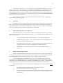
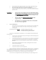
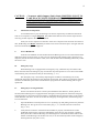
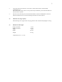
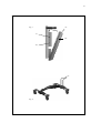
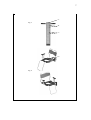
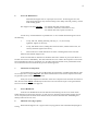
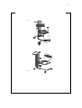
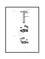
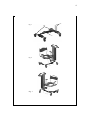
User’s Manual
Dawn® Care Hoist
2
All electronics, the battery as well as the actuator are mounted under the Bordeaux coloured
protective cover (Fig. 1, “B”) in order to protect against all protruding edges. Lift the protective cover
upwards and pull away from the Hoisting Unit. Grab the top of the battery and pull carefully at the
release handle of the battery. Place the battery at the wall-charger and “click” the charged battery on to
the Hoisting Unit. Close the protective cover by lifting it upward, press it forward towards the Hoisting
Unit and let it slide down into position.
A 24 V battery will charge in approximately 4 hours and has, fully charged, a capacity for
approximately 40 full lifting cycles.
4.
Operation:
Dawn Hoisting Unit is equipped with a hand control module, which may be used either by the
patient or by the carer. The hand control module has two knobs, which, each respectively elevates or
lowers the Hoisting Unit. The knob is to be pressed for as long as movement is required. The Hoisting
Unit stops as soon as a knob is released or end of travel is encountered.
5.
Fitting the Hoisting Unit on to a Base Unit:
Any Dawn Base Unit – be it with wheels or made for permanent, fixed mounting - (example
given in Fig. 2), is equipped with two Mounting rods (Fig. 2, “A”). The Hoisting Unit is fitted on to the
Base Unit as follows:
6.
1.
Carry the Hoisting Unit by its handle and place it over the two Mounting rods.
2.
Slide the Hoisting Unit down over the two Mounting rods, the rods engaging the two
holes in the bottom of the Hoisting Unit.
3.
Verify that the Hoisting Unit has come all the way down and is properly seated, with
no gap between the lower edge of the Hoisting Unit and the Base Unit.
4.
The Hoisting Unit is held in its place by its own weight, and further fixing is not
required.
Fitting of Patient Support Units:
In order to accommodate the great variety of hoisting needs, each of which will typically have
its respective requirement for the lowermost position of the Support Unit, the Dawn Hoisting Unit has
been designed with a number of fixing locations up along its height from top to bottom.
In the mounting plate of the Hoisting Unit (Fig. 3, “A”) are found two rows of slots (Fig. 3,
“B”) and two rows of tapped holes (Fig. 3, “C”). The lengths of the slots are coded in such a way that
no Support Unit can be fitted higher than acceptable on to the Hoisting Unit. Thus it is ensured, that no
Person Support Unit can be elevated so much, that the stability of Person Hoist is jeopardised.
When a Patient Support Unit is to be fitted on to the Hoisting Unit, the following steps MUST
be observed:
1.
2.
3.
If the Base Unit has got wheels, all four wheels must be locked.
Run the Hoisting Unit to its lowermost position.
Select the required lowest height for the Support Unit and insert the guide-taps at the
bracket of the Support Unit into the corresponding slots in the mounting plate of the
Hoisting Unit.
3
4.
5.
Push the bracket of the Support Unit down, until it is firmly seated and the fixingholes in the bracket match the tapped holes in the mounting plate.
Insert the two safety bolts (Fig. 4 “A”, (identical for all Support Units) into the
threads and tighten securely with the Allen key, stored under the Bordeaux-coloured
protective cover.
CAUTION: •
7.
If the bracket of the Support Unit is not fully flush with the
mounting plate, then the Support Unit is not correctly fitted
and no hoisting is to be attempted until the fitting has been
correctly completed.
•
All four guide-taps must be correctly seated in their
respective slots.
•
No hoisting is to be attempted, unless the two safety bolts
have been securely tightened.
Service & Maintenance:
Dawn Hoisting Unit is in principle service-free. All moving parts are self-lubricating
and require only normal cleaning with a damp cloth and, possibly, normal mild
cleaning agents.
The Hoisting Unit must NEVER
• be cleaned with high pressure cleaner
• be cleaned in autoclave, bed-washer or such.
• be cleaned with acids, organic solvents etc.
At least every second month the responsible user or carer should check out the Hoisting Unit
for the following:
1.
Verify the action of the Emergency Stop by activating this, whilst the Hoisting Unit is
running up/down respectively.
2.
Verify that the Hoisting Unit is securely fixed onto the chosen Base Unit grabbing the
top of the Hoisting Unit and forcefully trying to twist and waggle it. The Hoisting
Unit must not move or show any indications of looseness where it is attached to the
Base Unit.
3.
There must be no visible indications of cracks or disintegration in the structural
material of the Hoisting Unit.
4.
Verify that the handle is securely fixed.
5.
Verify that all visible screws are securely fixed.
In the case that faults or deficiencies should be observed in relation to point 1 - 4, the Hoisting
Unit is immediately to be taken out of service. The observed faults are to be noted in the inspection
record of the Service Manual and a Service Technician is to be called. The Hoisting Unit is not
permitted back into service until the Service Technician has given his written approval.
Loose screws are to be tightened securely before the Hoisting Unit is again being put to use.
4
CAUTION: • No matter which Support Unit is fitted, HOISTING IS NOT TO
TAKE PLACE UNLESS THE BRACKET OF THE SUPPORT
UNIT IS CORRECTLY FITTED AND THE SAFETY BOLTS
ARE SECURELY FASTENED INTO THE MOUNTING PLATE
OF THE HOISTING UNIT.
8.
Annual Service Inspection:
At a minimum once a year, the Hoisting Unit must be inspected by an authorised technician.
This service inspection is a legal obligation. The authorised technician carries out the inspection and
notes any possible repairs in the Service handbook.
Order your service inspection in due time. If the service inspection has not been carried out on
time, the Hoisting Unit MUST immediately be taken out of service and not be put to use again until the
Service Technician has given his approval.
9.
Service Handbook:
In the Service handbook all relevant data about the Hoisting Unit are to be noted. Faults and/or
deficiencies observed by the users, as well as service inspections and possible repairs carried out. It is
important, that all observations shall be noted, as this will facilitate later faultfinding and thereby reduce
the service costs.
10.
Emergency Stop:
Dawn Hoisting Unit is equipped with an emergency stop, which halts any movement of the
Hoist, when activated. The emergency stop is located on top of the protective cover close to the handle
of the Hoisting Unit, and can thus easily be activated (Fig. 1, “A”).
The emergency stop is activated by depressing the red button. The Hoisting Unit is only
operational again when the emergence stop has been de-activated. This is done by rotating the red knob
clockwise as indicated by the arrows. The knob then springs back out and the Hoisting Unit is again
operational.
11.
Emergency Lowering Function:
For the case that the electronic control system should become defective, while a patient is
elevated, Dawn Hoisting Unit is equipped with an emergency lowering function. When the emergency
lowering function is activated an electric impulse is transmitted directly from the battery to the actuator,
which thereafter runs down. In order to activate the emergency lowering function, the following steps
are to be followed:
1.
Open the Bordeaux coloured protective cover by lifting it up and pulling it back away from the
Hoisting Unit. This gives access to the battery (Fig. 1, “C”) and the electronic control box
(Fig. 1, “D”).
2.
Verify that the connector of the hand control module is properly inserted into the socket
underneath the electronic control box. Should this not be the case, the connector is pushed
firmly home after which the Hoisting Unit should again be controllable from the hand control
module. If the Hoisting Unit still does not react, it can be lowered by means of the emergency
lowering function (Se point 3. & 4.)
5
3.
At the front side of the electronic control box a small round window is found marked
“EMERGENCY ⇓”.
Pierce the window with a match or some pointed object and hold it pressed until the Hoist has
been lowered as required.
4.
Note the events observed prior to the functional failure in the Service Handbook and call an
authorised technician. Do not use the Hoisting Unit until it has been repaired.
12.
Maximum Carrying Capacity:
Dawn Hoisting Unit is approved for carrying patients with a maximum bodyweight of 120 kg.
13.
Dimensions and Weight:
Height, minimum:
Height, maximum:
Width:
Depth:
93 cm
159 cm
50 cm
24,5 cm
Weight:
21,5 kg
All dimensions are +/- 0.5 cm
6
Fig. 1
”A”
”C”
”B”
”D”
”A”
Fig. 2
7
”A”
Fig. 3
”B”
”C”
”A”
Fig. 4
2
In the mounting plate of the Hoisting Unit (Fig. 3, “A”) are found two rows of slots (Fig. 3,
“B”) and two rows of tapped holes (Fig. 3, “C”). The lengths of the slots are coded in such a way that
no Support Unit can be fitted higher than acceptable on to the Hoisting Unit. Thus it is ensured, that no
Person Support Unit can be elevated so much, that the stability of the Person Hoist is jeopardised.
When the Patient Support Unit with rotation-seat is to be fitted on to the Hoisting Unit, the
following steps MUST be observed:
1.
2.
3.
4.
5.
If the Base Unit has got wheels, all four wheels must be locked.
Run the Hoisting Unit to its lowermost position.
Select the required lowest height for the Support Unit and insert the guide-taps at the
bracket of the Support Unit into the corresponding slots in the mounting plate of the
Hoisting Unit.
Push the bracket of the Support Unit down, until it is firmly seated and the fixingholes in the bracket match the tapped holes in the mounting plate.
Insert the two safety bolts (Fig. 4 “A”, identical for all Support Units) into the threads
and tighten securely with the Allen key, stored under the Bordeaux-coloured
protective cover.
CAUTION: •
3.
If the bracket of the Support Unit is not fully flush with the
mounting plate, then the Support Unit is not correctly fitted
and no hoisting is to be attempted until the fitting has been
correctly completed.
•
All four guide-taps must be correctly seated in their
respective slots.
•
No hoisting is to be attempted, unless the two safety bolts
have been securely tightened.
Assembly of Patient Support Unit with Rotation seat
The most easy mounting of the back of the seat, armrest and footrest is achieved after the seat
module itself has been mounted onto the Hoisting Unit, as described. Go through the following steps:
1.
Run the Patient Support Unit up to the highest position by using the hand control
module. Thus it will be easier to fasten the back of the seat, armrest and footrest to
the underside of the seat unit.
2.
The threaded pins of the back are inserted into the tubular stubs on the rear side of the
seat unit. Thereafter the back is secured by screwing in one of the black thumb screws
into each of the two threaded taps, now visible on the inside of the frame of the seat
unit. Tighten the thumb screws as much as possible, however without using tools. The
Patient Support Unit is NEVER to be used unless the back of the seat is securely
fastened.
3.
The threaded pins of the footrest are inserted into the tubular stubs on the front side of
the seat unit. Thereafter the footrest is secured by screwing in one of the black thumb
screws into each of the two threaded taps, now visible on the inside of the frame of
the seat unit. Tighten the thumb screws as much as possible, however without using
tools. The Patient Support Unit is NEVER to be used unless the footrest is securely
fastened.
3
4.
The foot panel is fitted onto the footrest by pressing the slots of the panel down
home over the lower tubular part of the footrest.
5.
The threaded pins of the armrests are inserted into the tubular stubs on the sides of the
seat unit. Thereafter the arm rest is secured by screwing in one of the black thumb
screws into each of the threaded taps, now visible on the inside of the frame of the
seat unit. Tighten the thumb screws as much as possible, however without using tools.
If the Patient Support Unit is to be used for sideways-transfer directly from the bed, it
is recommended to fasten only the armrest closest to the Hoisting Unit with screws.
The opposite armrest is just fitted by inserting the pins into the tubular stubs on the
side of the seat frame. For the armrest, the thumb screws are only an additional fixing
means during handling. As soon as the armrests are loaded from above, they will lock
in position.
OBS! If the patient suffers from spasms and/or is not inherently laterally
stable, both armrests MUST ALWAYS be secured by use of the
thumb screws.
4.
Application of Dawn Care Hoist:
The Dawn Care Hoist is a “hybrid” between a conventional person hoist and a shower- and
commode chair. It offers, both to the carer and to the patient, a large number of advantages:
•
To the carer Dawn Care Hoist is a tool. Because you can lift the patient, the
severe strain on the carer’s back - normally associated with toileting, showering,
during chiropodi and personal care – can be avoided. Each year this type of work is
responsible for a large number of serious back injuries.
•
The Hoisting function combined with the rotation seat mean that the more mobile
patients may avoid being lifted by a conventional person hoist altogether.
CAUTION:
5.
1.
Turn the rotation seat so that the backrest faces toward the Hoisting Unit. Shift
the Person Hoist alongside the bed and remove the armrest facing the bed. Then
level the seat of the hoist with the mattress and assist the patient sideways onto
the seat, if need be, using a transfer board.
2.
Lower the seat to a suitable level and then roll out into the bathroom. Turn the
rotation seat, so that the patient has the side towards the Hoisting Unit and roll
the Care Hoist until the patient is seated above the toilet bowl.
3.
Roll the Care Hoist into the shower cabin and wash the patient
4.
Subsequently, the patient may be elevated to the washbasin and partake
in his own shaving, general toilette etc.
ALWAYS pay attention to the patients hands and feet when
lifting/lowering and when turning rotation seat.
Mirror reversal of Dawn Care Hoist:
Depending on the lay-out of the users home (e. g. wall relative to the toilet bowl), it may be
advantageous to mirror reverse the Care Hoist. This alteration is ONLY to be carried out by an
authorised technician.
4
6.
Service & Maintenance:
Dawn Patient Support Unit is in principle service-free. All moving parts are selflubricating and require only normal cleaning with a damp cloth and, possibly, normal
mild cleaning agents.
The Support Unit must NEVER
• be cleaned with high pressure cleaner
• be cleaned in autoclave, bed-washer or such.
• be cleaned with acids, organic solvents etc.
At least every second month the responsible user or carer should check the Support Unit for
the following:
1.
Verify, that nuts, holding mounting rods (Fig. 4, “A”) are securely
tightened. Tighten, if necessary.
2.
Verify, that thumb screws, holding the back of the chair, armrest and foot rest, are
securely fastened. Tighten if necessary
3.
There must be no visible indications of cracks or disintegration in the structural
material of the Patient Support Unit.
In the case that faults or deficiencies should be observed in relation to point 3, the Hoist is to
be taken out of service immediately. The observed faults are to be noted in the inspection record of the
Service Manual and a Service Technician is to be called. The Person Hoist is not permitted back into
service until the Service Technician has given his written approval.
7.
Annual Service Inspection:
At a minimum once a year, the Care Hoist must be inspected by an authorised technician. This
service inspection is a legal obligation. The authorised technician carries out the inspection and notes
any possible repairs in the Service Handbook.
Order your service inspection in due time. If the service inspection has not been carried out on
time, the Care Hoist MUST immediately be taken out of service and not be put to use again until the
Service Technician has given his approval.
8.
Service Handbook:
In the Service Handbook all relevant data about the Hoisting Unit are to be noted. Faults
and/or deficiencies observed by the users, as well as service inspections and possible repairs carried
out. It is important, that all observations shall be noted, as this will facilitate later faultfinding and
thereby reduce the service costs.
9.
Maximum Carrying Capacity:
Dawn Patient Support Unit is approved for carrying patients with a maximum bodyweight of
120 kg.
5
10.
Dimensions and Weight:
Seat width:
Seat depth:
Weight:
All dimensions are +/- 0.5 cm
46 cm
42 cm
8.75 kg
6
Fig. 1
Fig. 2
7
”A”
Fig. 3
”B”
”C”
”A”
Fig. 4
2
1.
Dismantle the four wheel brackets from the Base (Fig. 1, “B”) with an Allen-key.
2.
Turn the Base upside down.
3.
Re-fit the wheel brackets and tighten the screws securely.
4.
Fit the two mounting rods, as described under Point 2 above.
OBS. This work is only to be carried out by an authorised technician.
4.
Service & Maintenance:
Dawn Base Unit “60” and “70” is in principle service-free. All moving parts are selflubricating and require only normal cleaning with a damp cloth and, possibly, normal mild cleaning
agents.
The Support Unit must NEVER
• be cleaned with high pressure cleaner
• be cleaned in autoclave, bed-washer or such.
• be cleaned with acids, organic solvents etc.
At least every second month the responsible user or carer should check out the Support Unit
for the following:
1.
Verify that nuts, holding the mounting rods (Fig. 1, “A”) are securely fastened.
Tighten up if necessary.
2.
Verify that Allen-screws, holding the wheel brackets (Fig. 1, B”) are in place and
securely fastened. Tighten up if necessary.
3.
There must be no visible indications of cracks or disintegration in the structural
material of the Base Unit.
In the case that faults or deficiencies should be observed in relation to point 3, the Hoist is
immediately to be taken out of service. The observed faults are to be noted in the inspection record of
the Service Manual and a Service Technician is to be called. The Person Hoist is not permitted back
into service until the Service Technician has given his written approval.
5.
Annual Service Inspection:
The Person Hoist must be inspected by an authorised technician at least once a year. This
service inspection is a legal obligation. The authorised technician carries out the inspection and notes
any possible repairs in the Service handbook.
Order your service inspection in due time. If the service inspection has not been carried out on
time, the Hoisting Unit MUST immediately be taken out of service and not be put to use again until the
Service Technician has given his approval.
6.
Service Handbook:
In the Service handbook all relevant data about the Hoisting Unit are to be noted. Faults and/or
deficiencies observed by the users, as well as service inspections and possible repairs carried out. It is
important, that all observations shall be noted, as this will facilitate later faultfinding and thereby reduce
the service costs.
7.
Maximum User Weight:
3
Dawn Base ”60” and ”70” are approved for carrying patients with a maximum body weight of
120 kg.
8.
Dimensions and Weight:
Height:
Clearance under base frame:
Width, Base ”60”:
Width, Base ”70”:
Depth:
Turning radius:
Weight:
All dimensions are +/- 0.5 cm
16 cm
8 cm
58 cm
68 cm
73 cm
98 cm
12,5 kg
4
”A”
Fig. 1
”B”
”C”
Fig. 2
Fig. 3