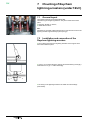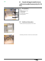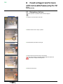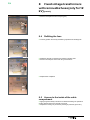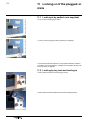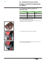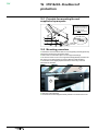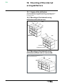
1
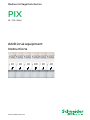
Medium Voltage Distribution
PIX
12 - 17.5 - 24 kV
Additional equipment
Instructions
www.schneider-electric.com
PIX
Contents
1
Schneider Electric at your service����������������������������������������������� 4
1.1 Your contacts������������������������������������������������������������������������������������ 4
2
State of delivery of the options & additional equipment����������� 6
3
3.1
3.2
3.3
3.4
Concerning this user manual�������������������������������������������������������� 7
Eco-design concept and revalorisation of the materials used��������� 7
Responsibilities�������������������������������������������������������������������������������� 7
Conventional symbols���������������������������������������������������������������������� 7
Tightening torques for standard assemblies (bolt + nut)������������������ 7
4
Fixing to anti-earthquake type floor��������������������������������������������� 8
4.1 Anchoring to the ground principle���������������������������������������������������� 8
4.2 Anchoring points������������������������������������������������������������������������������� 8
5
Assembly with 6 three phase synthetically insulated cables 5.1
5.2 5.3
5.4
(only for 12 kV)������������������������������������������������������������������������������� 9
Assembly of the cable troughs for cables with a dia. of 240mm2��� 9
Preparation of the cable connections����������������������������������������������� 9
Connection of the 6 three- phase cables with a dia. of 240 mm2� 10
Case of the mounting of lightning arresters����������������������������������� 10
6
6.1
6.2
6.3
Heating element�����������������������������������������������������������������������������11
References of the heating elements�����������������������������������������������11
Fitting position in the cable compartment���������������������������������������11
Attachment of a heating element assembly������������������������������������11
7
Mounting of Raychem lightning arresters (under 12 kV)��������� 12
7.1 General layout�������������������������������������������������������������������������������� 12
7.2 Installation and connection of the Raychem lightning arresters���� 12
8
Fixed voltage transformers with removable fuses (only for 12 kV)
8.1
8.2
8.3
8.4
8.5
8.6
������������������������������������������������������������������������������������������������������� 13
Presentation����������������������������������������������������������������������������������� 13
Additional information��������������������������������������������������������������������� 13
Extraction of a fuse������������������������������������������������������������������������ 14
Refitting the fuse���������������������������������������������������������������������������� 15
Access to the inside of the cable compartment����������������������������� 15
Characteristics of the fuses������������������������������������������������������������ 16
9
Withdrawable 12 kV voltage transformers, with removable 9.1
9.2
9.3
9.4
9.5
9.6
9.7
fuses���������������������������������������������������������������������������������������������� 17
Presentation of the 12 kV casing (cable compartment panel removed)��� 17
Possible padlocking configurations������������������������������������������������ 17
Characteristics of the EFEN - 2A fuses����������������������������������������� 17
Replacement of a fuse������������������������������������������������������������������� 18
Extraction of the VT trolley������������������������������������������������������������� 19
Extraction of the complete casing for access to the cables����������� 20
Refitting the casing������������������������������������������������������������������������� 21
10 Locking by key-locks for access to the cables compartment� 22
10.1 Preliminary operations�������������������������������������������������������������������� 22
10.2 Functioning of the locking procedure (with the possibility of a cables .
test)������������������������������������������������������������������������������������������������ 22
11 Locking-in of the plugged-in state��������������������������������������������� 24
11.1 Locking-in by padlock (not supplied)���������������������������������������������� 24
11.2 Locking by key lock and locking-in������������������������������������������������� 24
12 Locking-out of the closing or tripping operations for the HVX��� 25
12.1 Locking-out of the closing pushbutton for the HVX circuit breaker25
12.2 Locking out of the closing or tripping operations by padlock (not .....
supplied)����������������������������������������������������������������������������������������� 25
13
2
Tertiary resistor���������������������������������������������������������������������������� 26
AMTNoT077-02
PIX
Contents (contd.)
13.1 Access can be made via the rear of the functional unit����������������� 26
13.2 Replacement of the tertiary resistor����������������������������������������������� 26
14 Protective cover on the busbar connection nodes������������������ 27
14.1 References for the supply of a protective cover���������������������������� 27
14.2 Assembling the cover��������������������������������������������������������������������� 27
15 IPX1 & X2 - Double roof protection�������������������������������������������� 28
15.1 Principle for mounting the roof supplied as spare parts���������������� 28
15.2 Mounting procedure����������������������������������������������������������������������� 28
16 Mounting of the internal arcing deflectors�������������������������������� 29
16.1 Supply of the deflectors������������������������������������������������������������������ 29
16.2 Mounting of the internal arcing deflectors with side access���������� 29
16.3 Mounting of the internal arcing deflectors without side or rear access����29
16.4 Mounting of the vertical ”left-hand side” deflector�������������������������� 30
16.5 Arc deflectors at the front of the switchboard�������������������������������� 30
16.6 Mounting the ”front” deflectors������������������������������������������������������� 31
17 Gas evacuation tunnel in case of any eventual internal arcing�� 32
17.1 Example of the mounting of the tunnel supplied as spare parts���� 32
17.2 Assembly of the casings on to the roof of the functional units������ 32
17.3 Particular recommendations����������������������������������������������������������� 33
17.4 Assembly of the separated elements��������������������������������������������� 33
18 Installation of a “bus bar earthing switch” casing������������������� 35
18.1 The earthing switch casing is supplied separately.������������������������ 35
18.2 Handling the casing������������������������������������������������������������������������ 35
18.3 Preparation of the functional unit��������������������������������������������������� 35
18.4 Fixing the casing on to the roof������������������������������������������������������ 37
18.5 Busbar connections������������������������������������������������������������������������ 37
18.6 Connection of the low voltage wiring��������������������������������������������� 38
18.7 Operating manoeuvres with mounting of the deflectors���������������� 38
19
Ventilation fan casing mounted on the roof of the functional unit������������������������������������������������������������������������������������������������� 39
19.1 Mounting the ventilation fan casing������������������������������������������������ 39
19.2 Delivery of the casing��������������������������������������������������������������������� 39
19.3 Mounting the ventilation fan casing������������������������������������������������ 40
19.4 Maintenance of the fans����������������������������������������������������������������� 40
19.5 Cleaning the fans��������������������������������������������������������������������������� 40
19.6 Failure of a fan unit������������������������������������������������������������������������ 41
19.7 Spare parts������������������������������������������������������������������������������������� 41
19.8 Replacement of a fan unit�������������������������������������������������������������� 41
20
“Voltage Transformers” casing mounted on the roof of the fun
ctional unit������������������������������������������������������������������������������������ 42
20.1 Presentation of the VT casing�������������������������������������������������������� 42
20.2 Installation and connection of the VT casing��������������������������������� 42
21 Jib crane for the moving part����������������������������������������������������� 43
21.1 Presentation of the jib crane���������������������������������������������������������� 43
21.2 Fitting a moving part on to the handling table�������������������������������� 43
22
AMTNoT077-02
Notes��������������������������������������������������������������������������������������������� 46
3
PIX
1 Schneider Electric at your
service
Electrical equipment necessitates a particular attention and scrupulous
respect of the recommendations explained in this user manual. Operation
and maintenance may only be carried out by qualified personnel who have
received suitable authorisation for the operations and manoeuvres they are
responsible for performing. Schneider Electric’s After-Sales Service, which
is the nearest to you, is at your disposal for any type of aid or advice.
Reminder: All locking-out operations must be performed according to the
”General Safety Instructions booklet for Electrical Applications” and the
particular regulations for the network concerned.
1.1 Your contacts
France:
Schneider Electric Appareillage Moyenne Tension Bd de la Résistance
BP 84019 F-71040 Mâcon Cedex 9
Tel. : 33 (0) 3 85 29 35 00
Fax : 33 (0) 3 85 29 36 30
Toll free: 0 800 40 27 62
Freefone N° 0 800 40 27 62
Germany:
Schneider Electric, Sachsenwerk Königsbrücker Strasse 124, D-01099
Dresden
Tel. : + 49 (0) 351 8200
Fax : + 49 (0) 351 820 2342
Belgium:
Schneider Electric Belgium S.A., Route Zénobe Gramme, 33 Zoning des
Plénesses B-4821 Dison
Tel. : +32 (0) 87 320 350
Fax : +32 (0) 87 320 405
United Kingdom:
Schneider Electric UK Ltd Services, Frederick Road, Salford, M6 6QH,
England
Tel. : + 44 (0) 161 745 9090
Fax : + 44 (0) 161 745 4482
Switzerland:
Schneider Electric, Carl-Sprecher-Strasse 3, CH-5036 Oberentfelden
Tel. : + 41 (0) 6 27 37 33 33
Fax : + 41 (0) 6 27 37 31 80
4
AMTNoT077-02
PIX
1 Schneider Electric at your
service (contd.)
20
19
17
18
15
16
14
12
11
13
10
9
8
4
4
5
Switchgear additional equipment
AMTNoT077-02
7
6
5
PIX
2 State of delivery of the
options & additional equipment
Chapter Description
6
Equipment supplied
mounted
unmounted
■
Optional
add-on
4
Fixing to anti-earthquake type floor
5
Mounting of 6 three-pole synthetically insulated cables (in 12 kV)
No
6
Heating element
7
Mounting of Raychem lightning arresters (in 12 kV)
8
Fixed Voltage Transformers
■
No
9
Withdrawable voltage transformers (in 12 kV)
■
No
■
■
No
Yes
■
Yes
10
Locking by key-locks of the access to the cable compartment
■
No
11
Locking-in of the plugging-in operation
■
Yes
12
Interlocking of the closing or tripping operations
■
Yes
13
Tertiary resistor
■
14
Protective cover on the busbar connection nodes (under 12 kV)
No
■
No
15
IPX1 & X2 - Double roof protection
■
No
16
Mounting of the internal arcing deflectors
■
No
17
Gas evacuation tunnel in case of any eventual internal arcing
■
No
18
Installation of a ”bus bar earthing switch” casing
■
Yes
19
Ventilation casing mounted on the roof of the functional unit
■
Yes
20
”Voltage Transformer” casing mounted on the roof of the functional
unit
■
Yes
21
Jib crane boom for the moving part
■
Yes
AMTNoT077-02
PIX
3
Concerning this user manual
© - Schneider Electric- 2011. Schneider Electric, the Schneider Electric logo and their
figurative forms are Schneider Electric registered trademarks. The other trademarks
mentioned in this document, registered or not, belong to their respective holders.
This User Manual applies to the various options or additional equipment for the PIX
range.
3.1 Eco-design concept and revalorisation
of the materials used
The design and manufacture of our packaging are both in conformity with
the French government decree N° 98-638 of 20 July 1998, concerning the
account that is taken of environmental requirements.
3.2 Responsibilities
Schneider Electric declines any responsibility for the consequences:
■■ due to the non respect of the recommendations in this manual which
make reference to the international regulations in force.
■■ of any eventual aggressive climatic conditions (humidity, pollution, etc.)
occurring in the immediate environment of the materials that are neither
suitably adapted nor protected for these effects.
This user manual does not give details of the locking out procedures that must
be applied. The interventions described are carried out on de-energised
equipment (in the course of being installed) or locked out (non operational).
3.3 Conventional symbols
06
16
10
Code of a product recommended and marketed by
Schneider Electric
Value of the tightening torque
Example: 1.6 daN.m
Mark corresponding to a legend
CAUTION! Remain vigilant! Precautions to be
taken in order to avoid any accident or injury.
FORBIDDEN! Do not do it! The compliance with
this indication is compulsory, non-compliance
with this stipulation may damage the equipment.
INFORMATION - ADVICE Your attention is
drawn to a specific point for installation or operation.
3.4 Tightening torques for standard
assemblies (bolt + nut)
Threaded fasteners without grease: assembly with ungreased washers.
Threaded fasteners with grease : assembly with greased washers.
Use grease referenced :
01
Dimensions
AMTNoT077-02
Ungreased zinc-plated steel
threaded fasteners (daN.m)
Greased
stainless steel
fasteners
(daN.m)
Class 6.8
Class 8.8
A2-70
M6
0.7
0.9
0.7
M8
1.6
2.1
1.6
M 10
3.2
4.3
3.2
M 12
5
6.6
5
M 14
8.7
11.6
8.7
M 16
13.4
17.9
13.4
M 20
26.2
35
26.2
7
PIX
4 Fixing to anti-earthquake
type floor
4.1 Anchoring to the ground principle
Rear fixing
Front fixing
1
2
4.2 Anchoring points
■■ It is necessary to have access to the rear of the switchboard.
■■ Each functional unit must be fixed by 4 points:
□□ on the front left-hand and right-hand side with 1 H M10x30 bolt + 1 ES
washer + 1 flat washer and 1 fixing plug (drilling hole dia. 12mm)
□□ on the rear left-hand and right-hand side with 1 H M10x30 bolt + 1 ES
washer + 1 flat washer and 1 fixing plug (drilling hole dia. 12mm)
Do not use the 2 points on the front cross member (3).
■■ Front fixing (1).
1
3
■■ Rear fixing (2).
2
8
AMTNoT077-02
PIX
5 Assembly with 6 three phase
synthetically insulated cables
(only for 12 kV)
Front
5.1 Assembly of the cable troughs for
cables with a dia. of 240mm2
■■ This assembly is shipped in this condition.
Rear
5.2 Preparation of the cable connections
■■ Remove and protect the fuses.
■■ Dismantle the fuse supports.
■■ Disconnect the wires to the secondary sides and remove the voltage
transformers (VT).
■■ Dismantle the VT support, the front cross member and the floor panel.
AMTNoT077-02
9
PIX
5 Assembly with 6 three phase
synthetically insulated cables
(only for 12 kV) (contd.)
5.3 Connection of the 6 three- phase
cables with a dia. of 240 mm2
■■ Dismantle the assembly shipped already mounted (see § 5.1).
■■ Fix the 2 lateral supports (1) and the first sheet metal panel (at the
bottom) (2).
■■ Fix the earthing circuit (3a).
■■ Present and connect up the cables (A and B), with their grommets.
■■ Fix the second sheet metal panel (4) and the earthing circuit (3b).
2
1
Rear
3b
3a
A
3b
4
1
B
Front
■■ Top view.
■■ Strap the 2 cables and connect each of the earthing braids to the
earthing circuit (3).
■■ Proceed in an identical way for the other cables.
■■ Reassemble the floor panel, the VT support, and the front cross member.
■■ Reassemble and reconnect the voltage transformers, as well as the fuse
supports.
3a
3b
1
4
3b
Rear
1
2
Front
■■ Side view.
5.4 Case of the mounting of lightning
arresters
In the case of the mounting of lightning arresters at the front (see §
7), one can only carry out 2 x 3 cables.
10
AMTNoT077-02
PIX
6
Heating element
6.1 References of the heating elements
6.2
Voltage
110V
220V
Reference
AMTH23387-01
AMTC92324-01
Fitting position in the cable compartment
■■ The heating element is located on the bottom left hand side.
■■ Electrical connection is carried out by the left hand side.
■■ View of the heating element under its protective cover.
6.3 Attachment of a heating element
assembly
It is necessary to have access to the functional unit’s cable
compartment located on the left, in order to engage the fixing screws
for the support .
■■ Fix the support with an HM8x35 bolt.
400 mm
■■ Fit the screw by the left-hand cable compartment.
Front Face
AMTNoT077-02
11
PIX
7 Mounting of Raychem
lightning arresters (under 12 kV)
7.1 General layout
The lightning arresters are supplied dismantled.
There are 2 types of lightning arresters. They are mounted in the same
place:
■■ Raychem ”SPA09” or ”SPA12”,
■■ Varisil HE05 to HE12.
N.B.:
Dismantle any eventual voltage transformers in order to have access to the
lightning arrester support already in place (see § 2).
7.2 Installation and connection of the
Raychem lightning arresters
■■ Fit in position and mount the 3 lightning arresters on the support at the
front of the cable floor panel.
■■ Leave 1 nut on either side of the support (3) and the earthing circuit (4) (+
2 flat washers L12 (1) + 1 washer ES12 (2)).
3
4
2
1
1
■■ Fix the lug on the lightning arrester to the cable connection fittings
(central hole).
12
AMTNoT077-02
PIX
8 Fixed voltage transformers
with removable fuses (only for 12
kV)
8.1 Presentation
1
2
3
Legend
1 Mobile blocking off shutter.
2 Handling handles
3 Locking bracket
4 HV fuses switch-over lever
5 Blocking off panel.
4
5
8.2 Additional information
■■ Indicator plates showing the position of the HV fuses.
■■ Padlocking of the switch-over lever in the ”Closed” position.
AMTNoT077-02
13
PIX
8 Fixed voltage transformers
with removable fuses (only for 12
kV) (contd.)
8.3 Extraction of a fuse
This operation is possible with the cables energised.
■■ Lower the HV fuses switch-over lever
■■ Padlock the lever in the ”Open” position.
■■ Pull the blocking off shutter to the right.
■■ Unscrew the end of the fuse using a screwdriver.
The fuse is resting on a spring. Remain vigilant and take care
because the end piece will be ejected.
■■ Remove the end piece.
14
AMTNoT077-02
PIX
8 Fixed voltage transformers
with removable fuses (only for 12
kV) (contd.)
■■ Remove and replace the HV fuse (see § 8.6).
8.4 Refitting the fuse
■■ Correctly position the fuse by maintaining it pressed into its fitting hole.
■■ Release it carefully so that the fuse remains in its fitting hole.
■■ Screw in the end piece of the fuse using a screwdriver.
■■ Replacement completed.
8.5 Access to the inside of the cable
compartment
■■ Apply the general safety instructions for electrical locking-out operations
and the special rules for the network concerned.
■■ Respect the locking out procedures (wearing of protective gloves etc.).
AMTNoT077-02
15
PIX
8 Fixed voltage transformers
with removable fuses (only for 12
kV) (contd.)
■■ Dismantle the 4 fixing screws from the lower blocking off shutter.
■■ Remove this shutter.
■■ Dismantle the 4 fixing screws from the front plate.
■■ Remove the plate by pulling it out by its 2 handles.
8.6 Characteristics of the fuses
The characteristics of the fuse EFEN 2A are engraved on the little collars.
16
Voltage
12 kV
17.5 -24 kV
Reference
AGSC61689-01
AGSC13478-01
L
155
275
LT
160
280
AMTNoT077-02
PIX
9 Withdrawable 12 kV voltage
transformers, with removable
fuses
8
1
9.1 Presentation of the 12 kV casing (cable
compartment panel removed)
Legend
2
3
4
5
6
7
1
2
3
4
5
6
7
8
Rod for unlocking the fuses
Handle for disconnecting the fuses
Blocking off shutters for the fuse electrodes
Locking rod for the blocking off shutters
Handling handle
Low Voltage Connector
Secondary circuits breaking contacts
Wiring trough mask
9.2 Possible padlocking configurations
■■ Padlocking of the unlocking rod for access to fuses.
■■ Padlocking of the rod for locking and blocking off shutters.
9.3 Characteristics of the EFEN - 2A fuses
(see § 8.6)
The characteristics of the EFEN 2A fuse are engraved on one of the little
collars.
AMTNoT077-02
17
PIX
9 Withdrawable 12 kV voltage
transformers, with removable
fuses (contd.)
9.4 Replacement of a fuse
The marks correspond to those of the presentation of the casing (see § 9.1).
■■ Unscrew the 2 (or 3) fixing screws for the panel giving access to the cable
compartment.
■■ Lift up and remove the panel.
■■ Remove the padlock on rod for the blocking off shutters (4).
■■ Lift up the little rod (1).
■■ Pull the handle towards (2) to disconnect the fuses.
1
2
4
■■ Open the shutters masking the fuses (3) by pulling the first one to the
right, then the second to the left.
3
3
■■ Press the end cap and turn it to the left.
■■ Lift off the end cap and remove the fuse.
18
AMTNoT077-02
PIX
9 Withdrawable 12 kV voltage
transformers, with removable
fuses (contd.)
■■ Unscrew the little screw on the support.
■■ Replace the fuse with the same reference (see § 9.3).
■■ Put in the end cap and turn it to the right.
9.5 Extraction of the VT trolley
■■ Unscrew the 2 (or 3) fixing screws for the panel giving access to the cable
compartment.
■■ Lift up and remove the panel.
■■ Remove the padlock on rod for the blocking off shutters (4).
■■ Lift up the little rod (1).
■■ Pull the handle towards (2) to disconnect the fuses.
■■ Disconnect the LV plug (6).
1
2
6
4
■■ Open the shutters masking the fuses (3) by pulling the first one to the
right, then the second to the left.
3
AMTNoT077-02
3
19
PIX
9 Withdrawable 12 kV voltage
transformers, with removable
fuses (contd.)
■■ Hook up this plate in the edge of the functional unit.
5
■■ Unscrew the 4 fixing screws.
■■ Pull the trolley straight and slowly out with the handle (5).
The trolley is heavy because he is equipped with the voltage
transformers.
■■ Put again immediately the padlock in the upper hole.
■■ Lift off the access ramp.
9.6 Extraction of the complete casing for
access to the cables
■■ Apply the general safety instructions for electrical locking-out operations
and the special rules for the network concerned.
■■ Respect the locking out procedures (wearing of protective gloves etc.).
This operation must only be carried out with the cables de-energised,
earthing switch closed.
■■ Proceed with the operations in chapter 9.5.
■■ Dismantle:
□□ the 2 rails fixed on to the floor,
□□ the 5 fixing screws for the casing on the floor.
20
AMTNoT077-02
PIX
9 Withdrawable 12 kV voltage
transformers, with removable
fuses (contd.)
8
■■ Remove the removable floor.
■■ Dismantle:
□□ the 3 lateral fixing screws on the front and on each side,
□□ the wiring connector mask (8).
■■ Extract the casing.
■■ Access to the cables is now possible.
Before dismantling, note the position of the connections. They must
be slightly inclined towards the interior of the compartment.
9.7 Refitting the casing
Proceed with remounting operations, in the reverse order to those
described for dismantling.
AMTNoT077-02
21
PIX
10 Locking by key-locks for
access to the cables
compartment
10.1 Preliminary operations
Withdraw the moving part and bring it in to the ”test” position.
Ensure that there is no current voltage in the cables.
Close the earthing switch.
10.2 Functioning of the locking procedure
(with the possibility of a cables test)
■■ Lock the moving part in the withdrawn position, ”tests”.
■■ Recuperate the key.
■■ Introduce the recovered key into the door lock and turn it to unlock the
panel.
■■ Loosen the 2 (or 3) knurled screws at the bottom of the door.
22
AMTNoT077-02
PIX
10 Locking by key-locks for
access to the cables
compartment (contd.)
Door open, it is possible to open the earthing switch in order to carry
out tests on the cables.
■■ With the aid of the 2 handles, lift up the door and pull it towards you.
■■ Closing the door : Close and lower the door again in accordance with the
instructions on the yellow indicator plate.
■■ The door panel is in place whenever the marks are opposite and facing
one another
■■ Replace the lower knurled screws.
*
*AFTER CLOSING THE CABLE
COMPARTMENT DOOR, ENSURE THE
TWO MARKS ARE FACING EACH OTHER
AMTNoT077-02
23
PIX
11 Locking-in of the plugged-in
state
11.1 Locking-in by padlock (not supplied)
■■ Free access to the plugging-in device.
■■ Locking-in of the plugged-in state by padlock (not supplied).
■■ The passage holes are designed to accept padlock shackles of Ø 8mm.
■■ The fitting of several padlocks to a single point necessitates the use of an
accessory that is not supplied.
11.2 Locking by key lock and locking-in
■■ Device represented here not locked (key present).
■■ Device represented here padlocked and interlocked (key absent).
24
AMTNoT077-02
PIX
12 Locking-out of the closing or
tripping operations for the HVX
12.1 Locking-out of the closing pushbutton
for the HVX circuit breaker
■■ Padlocking device for the closing pushbutton.
■■ Closing pushbutton padlocked in place.
12.2 Locking out of the closing or tripping
operations by padlock (not supplied)
■■ Padlocking of the closing operation via the door.
■■ Padlocking of the tripping operation via the door.
Prohibition of a closing operation is materialised by the presence of a
solid pushbutton.
AMTNoT077-02
25
PIX
13 Tertiary resistor
13.1 Access can be made via the rear of the
functional unit
13.2 Replacement of the tertiary resistor
Power
700 W (15Ω − 40x370)
1000 W (12Ω − 50x370)
Reference
AMTH23388-02
AMTH23388-01
■■ Access is compulsory from the rear of the switchboard.
■■ Proceed with the locking out of the functional unit (HV and LV).
■■ Unbolt the rear middle panel of the functional unit: direct access can be
made to the resistor.
■■ Dismantle a fixing lug (screw + washer + nut) from the resistor.
■■ Unscrew the terminals at the extremities.
■■ Replace the resistor.
■■ Proceed with the operations in the reverse order for remounting.
26
AMTNoT077-02
PIX
14 Protective cover on the
busbar connection nodes (only
for 12 kV)
14.1 References for the supply of a
protective cover
Number
Description
Reference
2
Cover
DSL000799-01
4
HM6 nuts in polyamide ST416-158-008
PA6-6
4
HM6x12 screws in
polyamide PA6-6
ST411-058-251
100 g
Adhesive coating
ST318-250-001
14.2 Assembling the cover
Apply coating all around each of the three disks before closing each cover.
■■ Protective cover for the connection nodes.
■■ Cover installed during the assembly of the switchboard.
■■ Four fixing screws enable dismantling of the cover to be carried out in
order to verify the tightening torques.
AMTNoT077-02
27
PIX
15 IPX1 & X2 - Double roof
protection
15.1 Principle for mounting the roof
supplied as spare parts
2
C
A
C
IMPORTANT :
In the case of mounting the
arc deflectors as shown, the
IPX1 roof [1] must be
installed before the deflector
[2].
C
B
4
1
3
15.2 Mounting procedure
■■ Present the roof and make it slide on to the supporting bracket (3) already
riveted as an extension to the exhaust stack.
■■ Push in the roof fold until it clips on to the support bracket (3).
■■ Fix the front of the roof on to the support bracket (4) already riveted to the
rear of the LV box spacer block (3 screws H M8x30+3 ES8 washers).
■■ The double roof is slightly sloped towards the rear for any eventual
evacuation of rainwater.
2
1
4
3
■■ Side view of the assembly.
■■ The marks 3 and 4 are shipped already riveted on to the functional. unit.
28
AMTNoT077-02
PIX
16 Mounting of the internal
arcing deflectors
16.1 Supply of the deflectors
The arcing deflectors are supplied dismantled. It is imperative that you
follow the explanations supplied in order to respect the direction for
mounting on-site.
16.2 Mounting of the internal arcing
deflectors with side access
Rear
Front face
Rear
1. With rear access
Front face
2. Without rear access
16.3 Mounting of the internal arcing
deflectors without side or rear access
Any intervention in a LV wiring spacer
block, will necessitate dismantling of 2 or 3
deflector panels at the front.
Rear
Rear
Front Face
AMTNoT077-02
29
PIX
16 Mounting of the internal
arcing deflectors (contd.)
16.4 Mounting of the vertical ”left-hand
side” deflector
■■ Mount the supporting bracket (3) to the rear of the functional unit, at the
level of the arcing gas exhaust stack.
■■ Mount the far end extremity panel.
■■ Fix the supporting bracket at the front (5), on to the LV box.
4
5
Front face
3
Rear
■■ Install the ”side” deflector (4) by fixing it from above the far end extremity
panel.
■■ Fix this deflector at the rear of the supporting bracket and at the front on
to the front face deflector.
16.5 Arc deflectors at the front of the
switchboard
IMPORTANT :
1
2
30
■■ Carry out all of the wiring up and connections in the spacer block.
■■ Replace and fix the roof of the spacer blocks.
■■ Proceed with the mounting of the double roof (chapter15) before
mounting the deflectors.
■■ Proceed with mounting the deflectors (2) from left to right.
AMTNoT077-02
PIX
16 Mounting of the internal
arcing deflectors (contd.)
16.6 Mounting the ”front” deflectors
For operations to carry out installation of the deflectors, use suitably
adapted work gloves for this type of work.
■■ On each functional unit, fix the supporting bracket (1), on to the left-hand
part of the LV box. Use the existing fixing points on the roof of the LV spacer
block.
■■ At the far end extremity, on the last box, mount a supporting bracket (1)
on the right-hand side.
■■ Mount the ”front” deflector (2) between the brackets of the first and
second functional units.
■■ Proceed in this way, from left to right, right up to the far extremity of the
switchboard.
■■ Rear view of a special angular mounting.
■■ Front view of the angular mounting of the deflectors.
■■ Rear view of the mounting of the front deflectors.
AMTNoT077-02
31
PIX
17 Gas evacuation tunnel in
case of any eventual internal
arcing
17.1 Example of the mounting of the tunnel
supplied as spare parts
Front face
17.2 Assembly of the casings on to the roof
of the functional units (viewed from the front
face panel)
■■ Left-hand extremity: the casing is blocked off by a piece of sheet metal.
On the right, no separation from the following casing.
■■ The middle casings are open on both the right and on the left.
■■ Right-hand extremity : the casing is open for evacuation of the exhaust
gases.
32
AMTNoT077-02
PIX
17 Gas evacuation tunnel in
case of any eventual internal
arcing (contd.)
17.3 Particular recommendations
The physical evacuation of the gases has to be planned for and carried out by the customer.
The number and position of the outlets are defined on the switchboard’s single line diagram.
17.4 Assembly of the separated elements
7
9
6
Example of the
positioning
8
5
4
3
2
10
1
The fitting in place of the end blanking
pieces (4, 5, 8, 10) is carried out via the
interior of the functional unit (in accordance
with the instructions on the manuals
AMTNoT056 or AMTNoT060, § 4.3 to 4.7)
Front face
Legend
1
2
3
4
5
6
7
8
9
10
Right-hand bracket to be fixed to the rear duct.
Side cross member to be fixed to the upper part of the rear duct.
Left-hand bracket to be fixed to the rear duct.
Front intermediary end blanking piece.
Rear intermediary end blanking piece.
Intermediary frame to be fixed by overlapping between each of the functional units.
Upper protective cover.
Rear far end extremity blanking piece.
Lateral extremity sheet metal panel.
Front far end extremity blanking piece.
AMTNoT077-02
33
PIX
17 Gas evacuation tunnel in
case of any eventual internal
arcing (contd.)
■■ Rear support (2) equipped with brackets (1 & 3).
3
1
2
■■ Far end extremity equipped with the extremity sheet metal (9) of the
casing and the end blanking pieces (8 & 10).
8
10
9
■■ Intermediary frame (6) complete, equipped with end blanking pieces (4 & 5).
5
6
4
34
AMTNoT077-02
PIX
18 Installation of a “bus bar
earthing switch” casing
Front face
18.1 The earthing switch casing is supplied
separately.
Shown unmounted
18.2 Handling the casing
■■ The casing is supplied separately.
■■ Four fixed sling attachment points (1) allow for its handling.
1m
min.
4 slings
Caution when fitting the slings in place, for the wiring harness
strands may be flanged in close proximity to the sling attachment
points.
18.3 Preparation of the functional unit
■■ Remove the roof from the LV box (case with upper level passage ).
AMTNoT077-02
35
PIX
18 Installation of a “bus bar
earthing switch” casing (contd.)
■■ Remove the roof from the LV box (case without upper level passage ).
■■ Fit in place the new roof equipped, in front, with 2 passages for the LV
cables.
■■ Remove the roof above the busbars.
■■ Approach the casing by lifting it up by 4 slings.
36
AMTNoT077-02
PIX
18 Installation of a “bus bar
earthing switch” casing (contd.)
■■ Fit the casing in place.
■■ Fix the cover on to the indicator box on the earthing switch.
1
18.4 Fixing the casing on to the roof
In order to access the fixing points:
■■ remove the panels (2 & 3),
■■ engage it in the opening (4) of the busbars or by the interior of the
switchgear compartment (in accordance with the instructions on the user
manuals AMTNoT056 or AMTNoT060, § 4.3 to 4.7)
2
3
4
Use the HM8x20 screws supplied for fixing the casing.
Width of the
functional unit
650 mm
800 mm
1,000 mm
Number of fixing points
13
15
17
Approximate weight of
casing
120 kg
130 kg
150 kg
18.5 Busbar connections
■■ Gain access to the busbars in accordance with the instructions given in
user manuals AMTNoT056 or AMTNoT060, § 4.3 to 4.7
■■ Fit in position and fix the by-pass connections [5) whilst respecting the
order of the phases.
5
AMTNoT077-02
37
PIX
18 Installation of a “bus bar
earthing switch” casing (contd.)
18.6 Connection of the low voltage wiring
6
Pass the Low Voltage bundle of wiring cables in accordance with the wiring
path openings (6).
18.7 Operating manoeuvres with mounting
of the deflectors
Whenever the casing is inserted into an arc deflectors mounting, use the
special operating lever:
■■ AMT000223-05 --> 31.5 kA
■■ AMT000223-05 --> 40 kA
38
AMTNoT077-02
PIX
19 Ventilation fan casing
mounted on the roof of the
functional unit
19.1 Mounting the ventilation fan casing
Shown here without the LV
cables protective sheath
1
1
19.2 Delivery of the casing
■■ The casing is supplied separately.
■■ Two lifting brackets (1) enable handling by the use of slings.
■■ A metal cover (2) protects the LV wiring cables.
■■ The 3 ventilator fans are mounted and wired up.
2
Width of the
650 mm 750 mm 800 mm 1,000 mm
functional unit
Approximate
weight of casing
AMTNoT077-02
50kg
60kg
65kg
75kg
39
PIX
19 Ventilation fan casing
mounted on the roof of the
functional unit (contd.)
19.3 Mounting the ventilation fan casing
■■ On the roof of the functional unit, fix the casing by 6 screws (H M6x20).
■■ Viewed from under the casing
19.4 Maintenance of the fans
There is no filter, so it is necessary to clean the fans regularly
The frequency of cleaning needs to be adapted in accordance with the
speed of clogging up observed on site.
As an indicator, the service life of a fan unit under forced operation is
30, 000 hours at 40°C (3 years).
19.5 Cleaning the fans
De-energise the fans’ power supply circuit.
■■ On the roof, remove the 12 fixing screws (H M6x20).
■■ Lift up the upper plate by the front.
■■ The plate pivots on its rear fixing points.
40
AMTNoT077-02
PIX
19 Ventilation fan casing
mounted on the roof of the
functional unit (contd.)
■■ Maintain the plate in the vertical position.
The maximum height of the casing with the door open is: 1100 mm.
■■ Clean the fans using a clean dry paintbrush and a vacuum cleaner.
■■ Proceed in the reverse order to close the fan unit in casing.
19.6 Failure of a fan unit
In case of failure of a fan unit and in the two hours that follow, open the fan
units support plate (see § 19.5). Thus natural ventilation will be provided to
the functional unit.
However, it is necessary to decrease the load.
Next, as soon as it is possible, proceed with the replacement of the
defective fan.
19.7 Spare parts
Number
Description
Reference
3
Fan unit
AMT001339-02
19.8 Replacement of a fan unit
Open the fan units’ support plate (see § 19.5).
Disconnect the LV wiring from the defective fan unit (or the 3 fan units in
case of preventive maintenance).
Dismantle the fan which is fixed by 4 H M6x30 screws.
Ensure that the new fan unit is positioned in the same direction as
the others: the air must be expelled.
Proceed with the remounting operations in the reverse order to that for
dismantling.
AMTNoT077-02
41
PIX
20 “Voltage Transformers”
casing mounted on the roof of
the functional unit
20.1 Presentation of the VT casing
■■ VT casing mounted in place, on the roof of the functional unit.
1m
min.
■■ Two lifting brackets enable it to be handled by the use of slings.
20.2 Installation and connection of the VT
casing
■■ On the roof of the functional unit, fix the casing by 6 screws (H M6x20).
Front
■■ To gain access to the fixing points and for assembly of the by-pass
busbars, pass by the interior of the switchgear compartment (in accordance
with the instructions on the user manuals AMTNoT056 or AMTNoT060, §
4.3 to 4.7)
■■ Under 24 kV, mount the insulating screens at the level of the functional
unit’s roof passage.
■■ Example of a connection.
Width of the
functional unit
Approximate
weight of casing
42
650 mm
800 mm
1,000 mm
120 kg
130 kg
150 kg
AMTNoT077-02
PIX
21 Jib crane for the moving part
21.1 Presentation of the jib crane
(ref. : 330638-01) equipped with its lifting
beam (ref. : 330639-01)
1
3
Legend
1 Adjusting notches for the maximum load to be lifted (400 kg).
2 Jib crane handling handles
3 Pumping lever for lifting the load
4 Pushbutton to lower the load
5 Jib crane wheels
2
4
5
21.2 Fitting a moving part on to the handling
table
■■ The moving part must be placed on 2 stringers (min. section 30x30 mm).
2
■■ On the jib crane, adjust the lifting value on the upper arm of the jib crane’s
beam.
■■ Install the 2 brackets on to the moving part.
N.B.: They are delivered with this moving part.
■■ Ensure that the weight of the moving part (1), shown on its indicator plate
(2), is lower than that of the adjustment.
■■ Hook up the lifting beam to the jib crane’s lifting arm.
■■ Approach the jib crane by the front of the moving part.
1
AMTNoT077-02
43
PIX
21 Jib crane for the moving part
(contd.)
■■ Hook up the lifting beam to the 2 slinging points (brackets orientated
towards the rear).
■■ Begin pumping the jib crane to place the lifting beam under traction.
■■ The jib crane must remain truly in parallel with the moving part.
■■ Jib crane ready for the lifting operation.
44
AMTNoT077-02
PIX
21 Jib crane for the moving part
(contd.)
■■ Pump the handle to lift the moving part.
■■ Approach the handling table under the moving part (handles on the jib
crane side).
■■ Very slowly lower and place the moving part on to the table.
■■ Pull out the moving part towards the front in order to lock it on to the
handling table.
■■ Unhook the lifting beam.
■■ Remove the 2 brackets placed on the moving part.
■■ Remove the jib crane.
AMTNoT077-02
45
Appendices
AMTNoT077-02
22 Notes
46
Appendices
AMTNoT077-02
22 Notes
47
© 2011 Schneider Electric - All rights reserved
Schneider Electric
35, rue Joseph Monier
CS 30323
92506 Rueil-Malmaison Cedex, France
As standards, specifications and designs change from time to time, please ask for
confirmation of the information given in this publication.
RCS Nanterre 954 503 439
Capital social 896 313 776 €
www.schneider-electric.com
Publishing: Schneider Electric
Design: Schneider Electric
Printing:
AMTNoT077-02
This document has been printed
on ecological paper
02-2011