1
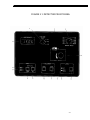
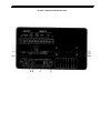
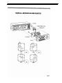
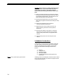
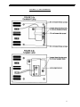
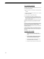
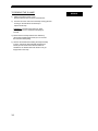
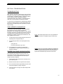
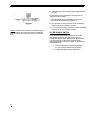
Models 500, 504, 506 Detector (equivalent to Linear Instruments Models 200, 204, 206) User Manual Kel-F is a registered trademark of the 3M Corporation. PS/2 is a registered trademark of the International Business Machines Corporation. CONTENTS TABLE OF CONTENTS Introduction i SECTION 1: CAPABILITIES AND SPECIFICATIONS Capabilities Specifications 1.1 1.2 SECTION 2: INITIAL OPERATION Unpacking 2.1 What You Will Need 2.1 Controls and Connections 2.2 Front Panel 2.2 Display 2.2 Rise Time Selection Switch 2.2 Range Selection Switch 2.2 Wavelength Selector 2.2 Wavelength Indicator 2.2 Ultra Violet (UV) Lamp Indicator 2.2 Visible (VIS) Lamp Indicator 2.4 Sample Light Intensity Switch 2.4 Reference Light Intensity Switch 2.4 Short Switch 2.4 Even, Switch 2.4 Wait Indicator Light 2.4 Over Range Light 2.4 Auto-Zero Switch 2.4 Rear Panel 2.5 Earth Ground 2.5 Recorder Outputs 2.5 Integrator Output 2.s Remote Auto-Zero 2.5 Remote Event 2.5 Remote Lamp Shut-Off 2.5 Earth Ground 2.5 Recorder Full Scale Voltage Selection Switches Filter By-Pass Switch 2.7 Integrator Offset Switch 2.7 Recorder Offset Switch 2.7 Power Switch 2.7 Power Connector 2.7 Fuse Block 2.7 Voltage Control Selector 2.7 Left Bulkhead 2.8 Lamp Housing Cover 2.8 Flow-Cell Housing Cover 2.8 Flow-Cell Exit Tubing 2.8 Flow-Cell Inlet Line 2.8 Setting Up 2.10 Location 2.10 2.5 Electrical Connections Setting Voltage Power Cord Setting the Recorder Full Scale Voltage Recorder Connections Integrator Connections Other Connections Auto-Zero Event Remote Lamp Shut-Off Fluid Connections Operation Setting Detector Parameters Wavelength Range Rise Time Performing a Test Run Shut-Down 2.10 2.10 2.10 2.12 2.12 2.12 2.12 2.12 2.13 2.13 2.13 2.14 2.14 2.14 2.15 2.15 2.15 2.16 SECTION 3: ROUTINE MAINTENANCE AND SERVICE Changing the Flow Cells 3.1 Cleaning and Disassembly of Flow Cells 3.4 Changing Lamps 3.5 The Deuterium Lamp 3.5 To Remove the D2 Lamp 3.5 To Install the D2 Lamp 3.6 The Tungsten Lamp (W) 3.8 To Install the W Lamp 3.8 To Remove the W Lamp 3.9 SECTION 4: TROUBLESHOOTING Light Intensity Diagnostics Proper Full-Scale Voltage Output Filter-Bypass Switch General Problems 4.1 4.1 4.2 4.3 SECTION 5: THEORY OF OPERATION 5.1 SECTION 6: APPENDICES A: Accessories and Replacement Parts B: Warranty C: Flow Cell Instructions INTRODUCTION INTRODUCTION: The Model 500 is a manual, variable wavelength ultraviolet/visible absorbance monitor for liquid chromatography. The unit is capable of performing applications from capillary to preparative scale, making it unmatched by any other detector in its class. This manual describes the installation, operation, troubleshooting, maintenance and service for the MODEL 500 detector. The manual is organized in the following manner: Section 1: This section briefly describes the capabilities and specifications of the unit. Section 2: This section describes the procedure for unpacking and installing the instrument, and for routine operation as an LC detector. Section 3: This section describes routine maintenance and service. Section 4: This section is a troubleshooting guide. Section 5: This section describes the theory of operation. Section 6: The appendices describe the warranty, accessories, and replacement parts. i CAPABILITIES SECTION 1: CAPABILITIES AND SPECIFICATIONS CAPABILITIES: This unit provides a unique combination of application flexibility and analytical power in an easy to use, low cost package. The instrument is capable of functioning as: 1) A variety Wavelength Detector from 190-380 mn with the standard deuterium lamp. 2) A variety Wavelength detector from 390-800 mn with the optional tungsten lamp. 3) An Analytical High Performance Liquid Chromatography (HPLC) Detector with the standard 6 mm pathlength, 9uL volume, stainless steel flow cell (Model 9550-0100). 4) An Analytical HPLC Detector with an optional 10 mm pathlength, 15uL volume, stainless steel flow cell (Model 95500122). 5) An Analytical HPLC Detector with an optional 6mm pathlength, 9uL volume, inert surface flow cell (Model 9550-0103) 6) A Microbore HPLC Detector with an optional 3mm pathlength, 1.2uL volume, stainless steel flow cell (Model 9550-0053). 7) A semi-preparative HPLC Detector with an optional 3mm pathlength, 4.5 uL volume, stainless steel flow cell (Model 95500101). 8) A Preparative Scale HPLC Detector with a variable pathlength (0-3mm), variable volume (0-4.6 uL), with stainless steel body (Model 9551-0070), and inert titanium body (Model 9550-0147). 9) An UV/Visible detector for use in pack-column Supercritical Fluid Chromatography or other high pressure applications with an optional 2mm pathlength, 250 nL volume, high pressure (7,000 psi) microbore cell (Model 9550-0150). NOTE: Consult your sales representative for other cells. 10) An UV/Visible detector for psuedo on column capillary detection applications such as Supercritical Fluid Chromatography or Micro-LC with an optional 250 um pathlength, 35 nL volume capillary flow cell (Model 9550-0149). 11) An UV/Visible detector for on column capillary detection applications such as Micro-LC and Capillary Zone Electrophoresis with an optional on column detection flow cell (Model 9550-0155). 1.1 SPECIFICATIONS: 1.2 Wavelength: 190-380 nm standard Deuterium lamp, 380-800 nm with optional Tungsten lamp. Wavelength Drive: Manual drive with mechanical wavelength indicator Band Width: 6nm Wavelength Accuracy: 1 nm Wavelength Precision: 0.1 nm Optical Methodology: Standard Deuterium lamp (190-380 nm) and optional Tungsten lamp (380-800 nm) light sources with concave holographic grating monochromator with double-beam optics, provisions for purging the monochromator Range Selections: 2.0, 1.0, 0.5, 0.2, 0.1, .05, .02, .01, .005, .002, .001, and .0005 AUFS Recorder Output: Single output with 10 mV, 100mV, or 1.0 V full scale capability with a switch providing + 10% full scale offset at each of the aforementioned settings. Integrator Output: 1.0 V/AU analog output, independent of range control but dependent upon autozero function. A switch supplying an additional +10.0mV is provided on the rear of the unit. Remote Controls: Rear Panel input for: Auto-Aero, Event Mark, and Remote Lamp Shut-Off Noise: 2 x 10 -5 AU/30 sec from 220-280 nm with 1.0 sec rise time (static, dry flow cell) Drift: <2 10-4 AU/hour after 1 hour warm-up Zero Adjust: Auto-zero circuit capable of offsetting greater than 1.5 AU with standard flow cell Chart Recorder Filter: Second Order Bessel filter with four user selected rise times (0.1, 0.3, 1.0, and 3.0 seconds). Rise time in seconds is 2 x Time constant in seconds. A filter bypass switch located on the rear panel provides an equivalent rise time of 0.1 seconds. Display: A 3 ½ digit LED displays absorbance and relative sample and reference light intensities Flow Cells: Pathlengths from 10 mm to 0.0 mm, cell volumes from 0 to 15 microliters, stainless steel, titanium, or Kel-Ftm*, contact materials, sapphire windows, 1000 psi pressure rating for stainless steel cells, 500 psi pressure rating for Kel-F tmcells, 2,000 psi pressure rating for variable pathlength preparative cells; 7,000 psi pressure rating for high pressure microbore cell Dimensions: 6 ¼ inches high, 13 ¼ inches deep, 9 ¾ inches wide. Weight – 20 lbs Line Voltage: 100, 120, 220, 240, 10% Cx, 50 OE 60 Hz. SPECIFICATIONS *Kel-F is trademark of the 3M Corporation. 1.3 SECTION 2: INITIAL OPERATION OPERATION UNPACKING: Carefully unpack the detector from the shipping container and inspect both the unit and packing for any signs of damage. If any damage is noted, contact the shipping company immediately. In addition to this manual, the shipping container contains a power cord, and any options which you ordered. Carefully check the packing list against the contents of the container. If anything is missing, check the packing materials carefully for the overlooked items. If items are missing, contact the factory or your dealer. Place the detector on the bench where it will be used and familiarize yourself with the location and function of the controls and connections. WHAT YOU WILL NEED: In addition to the detector itself, you will need the following items for setup and initial operation: 1) Strip chart recorder or integrator and connecting cables. 2) Liquid Chromatograph. 3) Column. 4) Standard test mix. 5) Appropriate solvents, reagents, etc. 6) Nuts, ferrules, appropriate to the column end-fittings being used. 7) Wrenches appropriate to column end-fittings. 8) Connecting tubing and union (if column cannot be connected directly to the cell). 2-1 CONTROLS AND CONNECTIONS: FRONT PANEL (See Figure 2.1): The following controls and indicators are located on the front panel: 1) Display: A 3 1/2 digit LED display provides absorbance values up to 1.999 AU. This display also provides relative sample and reference light intensities when Switches 8 (Sample Light Intensity) and 9 (Reference Light Intensity) are depressed, respectively. 2) Rise Time Selection Switch: A four-position rotary switch controls the degree of filtering performed by a Second Order Bessel filter. Rise times of 0.1, 0.3, 1.0, and 3.0 seconds can be chosen. Typically, Rise Time in seconds is equivalent to 2X the Time Constant in seconds. 3) Range Selection Switch: A twelve-position rotary switch controls the full scale output range for the rear panelpositioned Recorder Output. Full scale ranges of 2.0, 1.0, 0.5, 0.2, 0.1-05_02_01_005_002-001, and 0.0005 AUFS are provided. This switch does not effect the fixed 1 VAU output of the rear panel located integrator output. 4) Wavelength Selector: A mechanical continuous turn control selects wave lengths from 190 to 800 nm. Rotating this control clockwise decreases wavelength while counterclockwise rotation will increase wavelength. The arrow indicates the direction of rotation for increasing wavelength. CAUTION Do not force the knob below 180 nm or exceed 820 nm. Damage to the wavelength drive may result. 5) Wavelength Indicator: A mechanical three-digit indicator displays the wavelength of operation. 6) Ultra Violet (UV) Lamp Indicator: A green LED indicates that a Deuterium (D2) lamp is present in the instrument and is fit. 2-2 FIGURE 2.1: DETECTOR FRONT PANEL 2.3 7) Visible (VIS) Lamp Indicator: A green LED indicates that a Tungsten (W) lamp is present in the instrument and is fit. 8) Sample Light Intensity Switch: A momentary switch functions to display a value upon the LED display which is proportional to the light intensity at the sample cell photodiode. 9) Reference Light Intensity Switch: A momentary switch functions to display a value upon the LED display which is proportional to the light intensity at the reference photodiode. 10) Short Switch: A momentary switch functions to short the recorder output terminals to zero volts. This switch must remain depressed to function. This allows the user to set the pen position of a chart recorder. This switch does not effect the integrator output. 11) Event Switch: A momentary switch functions to send an event mark of approximately 20% deflection to the recorder output. This switch does not affect the integrator output. 12) Waft Indicator Light: A green LED indicates a fixed, zero volt recorder output. This occurs: a) upon powering up the unit. After the lamp has ignited, it is necessary to push Switch Number 14 -the Auto-Zero control. The Waft Indicator will then shut off and the recorder outputs will become active. b) upon pushing the Auto-Zero button. After the new zero value has been stored, the light turns off and the recorder outputs will become active. 13) Over Range Light: A green LED indicates a total absorbance in the flow cell which exceeds the auto-zero circuits capacity. The unit will still output voltages proportional to absorbance upon both recorder and integrator outputs. There will simply be an offset proportional to difference of the new baseline to that of a true zero baseline. For instance, if the auto zero-circuit functions to set the new zero value to .002 AU, all output absorbance values will contain a + 0.002 AU offset. The auto-zero circuit is capable of zeroing greater than 1.5 AU with the standard flow cell. 14) Auto-Zero Switch: A momentary switch activates an auto-zero circuit capable of zeroing greater than 1.5 AU. After pushing this button, the Waft Light will turn on and the recorder output will be shunted to zero volts. Within three seconds a new zero value will be calculated and the Waft Light will turn off. The Over-Range Light will illuminate when the total absorbance within the flow cell exceeds this circuits capacity. 2.4 REAR PANEL (See Figure 2,2); OPERATION 1) Earth Ground: This terminal is continuous with the earth ground. 2) Recorder Outputs: Two terminals supply an analog output to be used with a strip chart recorder or integrator. The full scale outputs of these terminals are selectable from 1Omv, 1 00mv, and 1.0 V. This output is dependent upon the position of the range and rise time controls. NOTE: DO NOT use this terminal as a negative ground for any output or input function. It may create ground loops resulting in excessive noise (see the Troubleshooting Section). 3) Integrator Output: Two terminals supply a fixed 1 V/AU analog output to be used with an integrator. This output is independent of the range control, rise time control, short and event switches, but dependent upon the auto-zero control. 4) Remote Auto-Zero: Two terminals provide a remote auto zero function. A momentary contact closure or TTL low activates the auto-zero circuit. 5) Remote Event: Two terminals provide an event mark with a momentary contact closure or TTL low. 6) Remote Lamp Shut-Off: Two terminals provide a remote means of turning the detector's lamp off. Lamps are shut off by providing a continuous contact closure or TTL low. Lamps are reignited by the interruption of a contact closure or TTL low. 7) Earth Ground: This terminal is continuous with the earth ground. *) Recorder Full Scale Voltage Selection Switches: Three two-position rocker switches control the full scale voltage of the recorder output. These switches do not effect the integrator output. *8) Pressing the top portion of this switch so that it rocks upwards to the on position, sets the full scale recorder output to 1.OV when Switches 9 and 10 are rocked downwards to the off position. *9) Pressing the top portion of this switch to the on position sets the full scale recorder output to 100 mV when Switches 8 and 9 are in the off position. 2-5 FIGURE 2.2:DETECTOR REAR PANEL *10) Pressing the top portion of this switch to the on position sets the full scale recorder output to 10 mV when Switches 8 and 9 are in the off position. 11) Filter By-Pass Switch: A single two-position rocker switch controls a bypass circuit for the Second Order Bessel filter. Pressing the top portion of this switch so that it is on renders the front panel Rise Time Control inert and results in effective rise time of 0. 1 seconds. OPERATION NOTE: If any of these three switches are simultaneously turned on, the recorder output will reflect an uncalibrated full scale. Insure that only one switch is on at a time. 12) Integrator Offset Switch: A single, two-position rocker switch provides an additional +10 mV offset to the fixed 1 VAU signal of the integrator output when the switch is in the on position. This switch does not effect the recorder output. This integrator offset is supplied to aid integrators incapable of zeroing for a negative drifting baseline. In most cases, it need not be used. 13) Recorder Offset Switch: A single, two-position rocker switch provides a +100% fixed offset to the recorder output. This offset is independent of full scale range or full scale voltage. This recorder offset does not effect the integrator output. 14) Power Switch: A single, two-position rocker switch turns the instrument on and off. Pressing the top portion of this switch so that it rocks upwards powers up the unit, while pressing the bottom portion of the switch so that it rocks downwards shuts the unit off. 15) Power Connector: A three-pin receptacle is provided that accepts a standard modular power line cord. 16) Fuse Block: Pry out this block to allow access to the fuses and voltage control. It contains one 1.0 amp slo-blow fuse (for 100-120 VAC operation) and two 0.5 amp slo-blow fuses (220-240 VAG operation). 17) Voltage Control Selector: A four position voltage selector allows the instrument to be operated at 100, 120, 220, or 240 VAC (50 Hz, 60 Hz). 2-7 1) Lamp Housing Cover: Remove the screw fastening this cover to gain access to the lamp. WARNING: NEVER remove the lamp housing cover when the detector power line Is connected. UV radiation from the deuterium lamp can damage skin and eyes. Both the deuterium and tungsten lamps get quite hot Care must be taken while handling them to avoid burns. 2) Flow-Cell Housing Cover: Remove the thumbscrew fastening this cover to gain access to the flow cell and sample photodiode. 3) Flow-Cell Exit Tubing: Connect this tube to a fraction collector, back-pressure device, or appropriate waste receptacle. NOTE: If a second detector is to be used in series with this detector, be sure to minimize the total tubing length from this outlet tube to the inlet tube of the second detector. This prevents excessive band broadening. NOTE- The outlet and inlet tubes O.D., I.D., and positions may vary depending upon the flow cell specified. See the flow cell owner's manual for more details. 2.8 LEFT BULKHEAD (See Figure 2.3): 4) Flow-Cell Inlet Line: Connect this tube directly to the column outlet N possible. FIGURE 2.3 DETECTOR LEFT BULKHEAD SETTING UP: LOCATION: Place the detector on a Laboratory benchtop in close proximity to the LC column outlet. Allow at least 5 inches of clear space between the rear panel of the unit and any wall or obstruction. This provides both access to the rear panel connections and a free f low of air. ELECTRICAL CONNECTIONS (See Figure 2.4): SETTING VOLTAGE: Check the voltage selector block located next to the power cord connector on the rear panel. The white plastic tab indicates the voltage for which the instrument has been configured. This has been factory set for the voltage appropriate to your country (100, 120,220, or 240 VAC; 50 or 60 Hz). If the voltage is incorrectly set you should reset it to the proper value before proceeding further. Insert the blade of a small screwdriver into the slot next to the connector and pry open the fuse block. Pull the fuse block straight out. Using tweezers or a pair of longnose pliers, pull the voltage selector card straight out. Orient the plastic indicator for the proper voltage as indicated in Figure 2.4, then press the selector card back into place. Insure that the fuse block is properly oriented for the selected voltage. This is done by rotating the block along its longitudinal axis until: a) The long single fuse faces outward for 100 and 120 VAC (1 amp slo-blow). b) The two short fuses face outwards for 200 and 220 VAC (0.5 amp slo-blow). Snap the fuse block cover back into place. POWER CORD: Power to the detector is provided by a standard modular power cord assembly. Connect the power cord to the receptacle next to the fuse block. 2.10 11 SETTING THE FULL SCALE VOLTAGE: Fig 2.5 NOTE: If any of these switches are simultaneously set to the on position (rocked upwards), the recorder output will reflect an uncalibrated full scale. Insure that only one switch is closed at a time. NOTE: These switches do not effect integrator output. NOTE: DO NOT connect the negative input of the recorder to either of the two earth ground terminals located on the rear of the instrument. This could establish a ground loop resulting in increased noise (see the Troubleshooting Section). NOTE: A fixed +10.0 mV offset can be set for the integrator output by pushing the top portion of the Integrator Offset Switch until it rocks upwards to the on position (Switch #5, Figure 2.5). This integrator offset is supplied to aid integrators incapable of zeroing for a negative drifting baseline. In most instances, it need not be used. The detector provides a single strip chart recorder channel. The full scale voltage for this channel maybe set at 10 mv, 100 mv, or 1.OV using a bank of switches located on the Rear Panel (See Figure 2.5). The instrument is factory configured to 10 mv full scale. To change the full scale voltage: 1) Press the bottom portion of Switch #3 so that it rocks downward to the off position. 2) For a 100 mv full scale output, press the top part of Switch #2 so that it rocks to the on position. 3) For a 1.0 V full scale output, press the top portion of Switch #1 so that it rocks to the on position. RECORDER CONNECTIONS: The recorder cables are connected at the VO terminal on the Rear Panel of the detector (see Figure 2.6). The cables should have a ¼” or so of bare wire or, more ideally, a spade connector. Connect the positive (+) input of the recorder to the screw labeled positive for the recorder output. Connect the (-) input of the recorder to the screw labeled negative for the recorder output. INTEGRATOR CONNECTIONS: The detector also provides a fixed-span output (I V/AU) for use with an integrator or data acquisition system. This is independent of the rise time control, full scale range and voltage settings of the unit. However, its output will reflect the zeroing of the Auto-zero circuit. Thus, a changing baseline can be corrected by pushing the Auto-zero button. Connect the input line of the integrator in an identical manner as was outlined for the strip chart recorder. OTHER CONNECTIONS: The detector provides for a number of other connections for accessories. You do not need to connect these in order to finish the initial installation and check-out. If you do not wish to connect the Remote Auto-Zero, Event Switch, and Lamp Shutoff at this time, you may proceed directly to the FLUID CONNECTIONS sections. AUTO-ZERO: The Auto-zero connection on the Rear Panel (See Figure 2.6) duplicates the function for the Zero Button on the Front Panel whenever it is connected to a momentary contact closure or TTL low. 2.12 Connect the triggering device so that the positive (+) line is connected to the positive pole and the negative (-) line is connected to the negative pole of the remote Auto-Zero terminal. The remote auto-zero may be triggered by shunting across its two input terminals. Fi2.6 EVENT: The Event connection on the Rear Panel (see Figure 2.6) duplicates the function of the Event Button on the front panel whenever it is connected to a momentary contact closure or TTL low. Connect the triggering device so that the positive (+) line is connected to the positive pole and the negative (-) line is connected to the negative pole of the remote Event terminal. The remote Event may be triggered by shunting across its two input terminals. REMOTE LAMP SHUT-OFF The Remote Lamp Shut-Off connection on the Rear Panel (see Figure 2.6) turns the lamp off when supplied with a constant contact closure or TTL low. Connect the triggering device so that the positive (+) line is connected to the positive pole and the negative (-) line is connected to the negative pole of the Remote Lamp Shut-off terminal. The Remote Lamp Shut-off may be triggered by shunting across its two input terminals. Interruption of this shunt reignites the lamp. FLUID CONNECTIONS: The Detector fluid inlet is the lower tube which protrudes from the rear wall of the cell compartment (see Figure 2.3). As a general rule, the less tubing between the column outlet and the flow cell, the better. Ideally, the column outlet should be connected directly to the detector inlet line. If this is not possible, you should use a minimum length of narrow bore (0.010 inch I.D.) connecting tubing and a zero dead volume union. Because different columns use different fittings, the detector is supplied with a bare tube end to allow connection to any column accepting 1/16 inch O.D. tubing. You should use nuts and ferrules suitable to your column. Connect the cell outlet (the upper of the two tubes which protrude from the rear wall of the cell compartment) to a line leading to an appropriate waste reservoir. If bubble formation in the detector cell causes problems, you may wish to connect the cell outlet to a restrictor or back pressure device providing 20-60 psi back-pressure. 2.13 Fig 2.6 NOTE: If excessive noise is noted after interfacing the detector with a remote triggering device, a ground loop may have been established. It may be necessary to insure that the remote device has a negative output which is isolated from the earth ground. NOTE: If the lamp is turned off by the Remote Lamp Shutoff and then reignited, the fixed zero volt recorder output function indicated by the front panel located Waft Light will not be maintained. The recorder output will return to a level representative of the current absorbance and last stored zero value. The Auto-zero circuit should be activated. NOTE: Detailed descriptions of the flow cells you specified are contained in the appendices of this manual. NOTE Tubing size and position is different for the adjustable pathlength preparative flow cells, high pressure microbore flow cell, off column capillary flow cell, and on column capillary flow cell. See their owner's manuals for details. NOTE: Before connecting any new tube or column to the detector, flow several mL of clean solvent through the new tube to a waste reservoir. This will clean any particulates or oil that may be residing in the tube that could clog the heat exchanger or contaminate the sample cell of the detector. OPERATION: Turn on the HPLC System and allow the column to equilibrate with the flowing eluant (the time required will depend on your particular column and eluant). If you have not already done so, turn ON the power to the detector using the switch located on the lower rear panel. Turn the Range selector knob to 2.OAUFS and Rise Time selector to 1.0 seconds. Adjust the wavelength drive to the appropriate wavelength for your test mix. NOTE When the unit is first turned on, the LED indicator will indicate random absorbances. Typically a -1 or 1 will be indicated with no significant figures to the right of the decimal point. The Waft Light will be lit. The deuterium lamp will require approximately 20 seconds for ignition, while the tungsten lamp lights almost instantaneously. During the lamp ignition period, adjust the chart recorder pen to your desired position. After lamp ignition, the appropriate lamp indicator (UV for D2, VIS for W) will light, an absorbance will be displayed on the LED display, and the Waft Light will still be [ft. During this interval, the recorder output will be fixed at zero volts while the integrator output will transmit a voltage related to the present flow cell absorbance and last zero value stored in the auto-zero circuits memory. To activate the recorder output, press the Auto-zero button. This feature protects the chart recorder from rapidly moving and slamming into its margin if the detector is inadvertently set at a sensitive range and a large discrepancy exists between flow cell absorbance and the last stored zero value. After the lamp has ignited and the Auto-zero button has been pushed, ft will be necessary to push the SHORT Switch in order to set the recorder output to zero volts to allow adjustment of the chart recorder pen. The SHORT Switch does not effect the integrator output. NOTE Allow approximately 1.0 hour warm-up period for the detector to reach its optimal performing state. Set the detector to a more sensitive range such as 0.01 AUFS and monitor the baseline until a straight, non-drifting baseline is noted. SETTING DETECTOR QONTROLS: After the column has equilibrated and the detector has warmed up, prepare a sample to be injected. Set the detector parameters according to the following guidelines. WAVELENGTH: Turn the wavelength selector until the wavelength indicator coincides with the wavelength of maximal absorbance for your sample. The best wavelength ranges are: a) 190-380 nm for the standard deuterium lamp. b) 380-800 nm for the optional tungsten lamp. 2-14 Rotating this control clockwise decreases wavelength while a counter clockwise rotation will increase wavelength. The arrow indicates the direction of rotation for increasing wavelength. CAUTION, Do not try to go below 180 nm or exceed 820 nm. Damage to the wavelength drive may result RANGE: OPERATION NOTE: It is possible to turn this NOTE: It is possible to turn this control beyond 190 or 800 nm. These wavelengths are outside the instruments specified range. RISE TIME: NOTE: For maximal wavelength reproducibility, a given wavelength value should always be approached from the same direction. For example, if initial work at 254 nm was performed moving the wavelength control from 210 nm to 254 nm, all subsequent work at 254 nm should be performed by arriving at that wavelength from a value about ten nanometers less. As a general rule a rise time equivalent to 1 /10 of the fastest peak base-width should be used. Too short a rise time results in an unnecessarily noisy baseline, while too long a rise time may distort the shape of the peak. For most LC applications, a rise time value of 1.0 second is sufficient. NOTE: Although the Second Order Bessel filter may distort peak shape at long rise times, peak area is always conserved. Thus integration can be safely performed for the purpose of quantitative analysis from the recorder output. Rotate the Range Selector Switch to an appropriate full scale absorbance for your sample. Full scale ranges of 2.0,1.0,0.5, 0.2, 0.1, 0.05,0.02,0.01,0.005,0.002, 0.001, and 0.005AUFS are provided. This switch does not effect the fixed I V/AU output of the rear panel located integrator output. The Second Order Bessell filer provides user selectable rise times of 0.1, 0.3, 1.0, and 3.0 seconds. For extremely fast peaks, a filter by pass switch is provided on the rear panel (Figure 2.5, Switch #6). Pressing the top portion of this switch turns the circuit on and renders the rise time selector inert and results in an effective rise time of 0.1 seconds. NOTE: Typically, rise time in seconds is equivalent to 2 times a time constant in seconds. PERFORMING A TEST RUN: After setting the detector parameters, the instrument should be zeroed. As a general rule, it is a good idea to auto-zero the detector prior to each injection. Zero the detector, inject your sample, and activate the event mark. You should note an approximate 20% deflection on the recorder. Note the peaks as they appear on the strip chart recorder. Readjust the parameters of wavelength, range, and rise time to optimize the chromatography. 2-15 NOTE: After the lamp is remotely reignited, the strip chart recorder output will transmit a voltage related to the current flow cell absorbance and the last stored zero value in the auto-zero circuit. SHUT DOWN: As a general rule, it is recommended that the flow cell be flushed with several volumes of clean, non-ionic eluant. This is especially important if ionic buffer solutions have been used. After flushing, simply turn the the power switch on the back panel to the off (downwards) position. The lamp may be shut-off remotely with the rear panel located Lamp Shut-off terminal. This will prolong lamp life while the detector is not in use. The lamp is shut off by providing a continuous contact closure or TTL low. The lamp is reignited by interrupting the contact closure or TTL low. 2.16 SECTION 3: ROUTINE MAINTENANCE AND SERVICE CHANGING THE FLOW CELLS: SERVICE The detector accommodates a variety of flow cells with different pathlengths, illuminated volumes, and wetted materials for different applications. A complete listing of the available cells is provided in Appendix A. All flow cells are provided premounted in a holder assembly to minimize alignment problems. Detailed instructions specific to the various flow cells are included with the flow cells themselves. This section of the manual provides general guidelines for flow cell service and maintenance. The f low cell is located in the forward housing on the left hand side of the detector (Figure 3.1). To change the flow cell: 1) Make sure the power cord is disconnected from the rear panel of the detector. 2) Disconnect the cell inlet tube from the column or connecting tube and free the cell outlet tubing. 3) Remove the cell cover by unscrewing the thumbscrew and pulling the cover straight back to expose the photodiode mount. 4) Unscrew the two thumbscrews on the photodiode mount and pull the photodiode mount straight back (see Figure 3.2). The connecting cable is long enough to allow the photodiode mount to rest on the bench-top. CAUTION: Be careful to avoid scratching or putting fingerprints on the photodlode. The photodiode surface should be cleaned with spectroscopic grade methanol and lint-free Ions paper. 5) Loosen the thumbscrew holding the tubing strain relief clamp in place and gently pull the clamp towards you far enough to disengage the tubing from the clamp. 6) Unscrew the two thumbscrews securing the cell holder assembly in place and pull the cell holder assembly straight back toward you to remove it. 7) Replacement cells are mounted pre-aligned in a cell holder assembly. Installation reverses the removal process. 3.1 FIGURE 3.1: FLOW and LAMP ASSEMBLIES 1. 2. 3. 4. 5. 6. 7. 8. 9. 10. 11. 12. 13. 14. 15. 16. 3.2 Cell Cover Photodiode Retaining Screw Photodiode Mount Tubing Strain Relief Thumbscrew Cell Retaining Screws Tubing Strain Relief Clamp Cell Body Assembly Cell Holder Cell Holder Thumbscrews Lamp Light Shield Screw Lamp Light Shield Deuterium Lamp Assembly and Plug Lamp Thumbscrew Standoff Lamp Thumbscrew Lamp Cover Lamp Cover Screw FIGURE 3.2: FLOW CELL ASSEMBLY 3.3 CAUTION: Avoid scratching or putting fingerprints on the flow cell windows or the monochromator lens which Is revealed upon cell removal. These Items should be cleaned with spectroscopic grade methanol and lint-free paper 8) Slide the cell holder assembly onto the alignment dowels. The inlet line should enter the bottom of the cell in order to provide efficient bubble flushing. Securely fasten the cell holder assembly with the two thumbscrews. 9) Slip the inlet and outlet tubes into the slots in the strain relief clamp and tighten the thumbscrews holding the clamp in place. 10) Replace the photodiode mount and fasten it securely with the two thumbscrews. 11) Replace the cell cover (be careful not to pinch the cable or the tubing) and fasten it securely with the thumbscrew. 12) Reconnect the inlet line to the column or connecting tubing and reconnect the outlet tubing to the fraction collector, back-pressure device, or appropriate waste reservoir. 13) Reconnect the power cord to the rear panel of the detector. CLEANING OF FLOW CELLS: If at all possible, we discourage the disassembly of flow cells for routine cleaning purposes. Most cells can be adequately cleaned by flushing with several milliliters of appropriate solvent. We recommend the following solvents for this purpose: 1) 2) 3) 4) 5) NOTE: Use only spectroscopic grade solvents. 3.4 Methanol Tetrahydrofuran Methylene Chloride HPLC Grade Water 6 N Nitric Acid followed by flushing with HPLC Grade Water If flushing proves to be inadequate, consult the owner's manual for the cell model with which your detector is equipped for flow cell disassembly directions. CHANGING LAMPS: SERVICE The detector has provisions for accepting two light sources: A deuterium (D2) lamp assembly (1 90-380nm) and tungsten (W) lamp assembly (380-800nm). If your dete ctor was ordered ready for work in the visible spectrum, it contains the W assembly. If you ordered your detector in the standard configuration, it is equipped with the D2 assembly. Only one lamp can be mounted In the Instrument at a time. Consequently, moving from the UV to the visible requires the removal of the D2 assembly and installation of the W assembly. All lamp assemblies are supplied pre-aligned and no further alignment adjustments are needed when changing from one lamp to another. THE DEUTERIUM LAMP: The Deuterium Lamp (132) is rated for 1,000 hours of life to 112 the original intensity (this does not mean that the lamp will burn out after 1,000 hours, merely that its intensity will be reduced to 50% of the original output). Each D2 lamp assembly is equipped with a chronometer indicating the total hours of operation. The chronometer is read by noting the position of the "gap" in the mercury tube against the graduated background. To check the lamp intensity: 1) Power up the unit if it is not already on. Waft for a period of approximately 10 minutes. 2) Adjust the wavelength drive to read 254 nm from a position at least 10 nm below. 3) Push the Reference Light Intensity Switch. 4) If the displayed value is equal to or greater than 100, the lamp is good. If the displayed value is between 99 and 50, the lamp is marginal. If the displayed value is less than 50, the lamp should be replaced. As a general rule, the D2 lamp should produce reference light intensities greater than 50 from 190-380 nm. TO REMOVE THE D2 LAMP: 1) Make sure that the power cord is disconnected from the rear panel of the detector. 2) Unscrew the screw and remove the lamp housing (the rear housing on the left side of the detector to expose the lamp (see Figure 2.3). 3.5 2) Unscrew the screw and remove the lamp housing (the rear housing on the left side of the detector) to expose the lamp (see Figure 2.3). CAUTION UV light can damage eyes and skin. Always disconnect the power cord before working In the vicinity of the lamp. The D2 lamp gets quite hot Care must be taken while handling It to prevent burns. Always allow the lamp to cool before removing It. 3) Disconnect the UV lamp lead from the detector by gently pulling it straight back toward you. DO NOT twist the connector while pulling (see Figure 3.3a). 4) Unscrew the two thumbscrews holding the lamp mount in place, and pull the lamp mount straight back towards you. Be careful not to lose the two aluminum standoffs or the thumbscrews. Be careful not to get fingerprints on the lamp. TO INSTALL THE Q2 LAMP: 1) Slide the lamp mount onto the alignment dowel located to the left of the monochromator's aperture (the mount has a pre-drilled hole to accommodate the dowel) (see Figure 3.3a). The lamp leads should emerge from the top of the lamp. 2) Use the thumbscrews and aluminum standoffs to attach the lamp assembly to the detector. Connect the lamp lead to the upper of the two terminals in the lamp compartment. NOTE: No harm will be done if the lamp is plugged into the wrong connector, but the lamp will fail to light. 4) Replace the lamp housing and its retaining screw. CAUTION: NEVER loosen the screw holding the lamp to the mount, and never attempt to rotate or move the lamp up or down In the mount. Doing so will degrade the system performance. The lamp is provided as a pre-aligned assembly. 3-6 FIGURE 3.3: LAMP ASSEMBLIES 3.7 THE TUNGSTEN LAMP (W): The lifetime of the tungsten lamp is approximately 2,500 hours. To check the W lamp intensity: 1) Power up the unit if it is not already on. Waft approximately 10 minutes. 1) Adjust the wavelength drive to read 550 nm from a position at least 10.0 nm below. 3) Push the Reference Light Intensity Switch. 4) If the displayed value is equal to or greater than 100, the lamp is good. If the displayed value is between 99 and 50, the lamp is marginal. If the displayed value is less than 50, the lamp should be replaced. In general, a value less than 15 for the 380-450 nm range and less than 50 for 450-800 nm range is indicative of a bad W lamp. The W lamp should be used for all wavelengths above 380 nm. The user may notice higher relative light intensities for the D2 than the W lamp from 380-450 nm. However, this light represents the second order diffraction spectra of the D2 lamp and should not be used. In order to install the Tungsten Lamp Assembly, the D2 lamp assembly must first be removed. To remove the D2 lamp, see the instruction entitled “To Remove the D2 Lamp" just prior to this section. TO NSTALL THE W LAMP: 3.8 1) Slide the W Lamp Assembly along the same alignment dowel used for the D2 lamp (see Figure 3.3b). 2) Fasten the W lamp assembly using the same two screws and aluminum standoffs that are used to fasten the D2 lamp assembly to the detector. 3) Plug the W lamp power cord into the lower of the two receptacles located on the detector. 4) Replace the lamp housing and its retaining screws. TO REMOVE THE W LAMP: 1) Make sure that the power cord is disconnected from the rear panel of the detector. 2) Unscrew the screw and remove the lamp housing (the rear housing on the left side of the detector) to expose the W lamp. WARNING: The W lamp gets quite hot. Allow sufficient time for it to cool before attempting Its removal. 3) Disconnect the W lamp lead from the detector by gently pulling straight back toward you. Do not twist the connector while pulling. 4) Unscrew the thumbscrews holding the lamp assembly in place, and pull the lamp assembly straight back toward you. Be careful not to lose the aluminum standoffs or the thumbscrews. Be careful not to get fingerprints on the lamp. 3.9 SERVICE SECTION 4: TROUBLESHOOTING TROUBLESHOOTING: Most "problems" with HPILC detectors are, in fact, caused by other parts of the system. Noisy and drifting baselines, poor reproducibility in quantitative analysis, and similar problems are more often the result of dissolved air bubbles, contaminated eluants, dirty samples, or damaged columns rather than of actual problems with detector hardware. In order to focus more effectively on troubleshooting detector problems, we will first discuss on-board diagnostic tips and later present a troubleshooting table organized by symptom, cause, remedy. LIGHT INTENSITY DIAGNOSTICS: The detector provides the capability of monitoring relative light intensities at both the sample and reference photodiodes. If an unusually noisy baseline is noted, relative intensities of reference and sample light should be assessed. Acceptable values are dependent upon the flow cell used, wavelength of operation, and background absorbance. The basic guidelines are as follows: 1. A clean flow cell and good lamp will yield a reference to sample light ratio of approximately 2:1. 2. An unusually high reference to sample light ratio may indicate: NOTE: This reference light value of 50 is only applicable for wavelengths within the acceptable range for a given lamp. a) dirty flow cell b) excessive absorbance by solvent 2) An acceptable ratio of reference to sample light accompanied by a reference light level less than 50 indicates a bad lamp. PROPER FULL SCALE VOLTAGE OUTPUT: NOTE The user may notice higher relative light intensities for the deuterium lamp than the tungsten lamp from 380-450 nm. However, this light represents the second order diffraction spectra of the deuterium lamp and should not be used. An exceptionally noisy baseline may also be due to an inappropriate full scale voltage output setting for the strip chart recorder. To test if the detector's full scale output voltage is properly configured: 1) Press the short switch and move the recorder pen to a good reference point. 2) Release the Short Switch and press the Event Switch. 3) The event mark should be approximately 20% full scale if the output voltage is properly configured. 4) If the event mark is too large, the output voltage needs to be reduced. 4-1 5) If the event mark is too small, the output voltage needs to be increased. The instrument is factory configured to 10 mV full scale. To change the full scale voltage: 1) Press the bottom portion of Switch #3 so that it rocks downward to the off position (see Figure 4. 1). 2) For a 100 mV scale output, press the top part of Switch #2 so that it rocks to the on position (upwards). 3) For a 1.0 V full scale output, press the top portion of Switch #1 so that it rocks to the on position (upwards). NOTE- If any of these three switches are simultaneously set to the on position, the recorder will reflect an uncalibrated full scale output. Insure that only one switch is closed at a time. 4-2 FILTER BYPASS SWITCH: An exceptionally noisy baseline not responsive to the Rise Time Selector on the front panel may be the result of an activated Filter Bypass Switch. When the Filter Bypass Switch is on, the front panel rise time control is bypassed and a resultant rise time of 0.1 seconds is created. To deactivate the Filter Bypass Circuit: 1) Push the bottom portion of Switch #6 (see Figure 4.1) until it rocks downward to the off position. 2) The Rise Time Selector should now function. TROUBLESHOOTING TROUBLESHOOTING GUIDE: GENERAL PROBLEMS: Remaining noise and drift problems can be due to various sources within and external to the system. The following table provides a checklist of symptoms, possib le causes, and some remedies. SYMPTOM CAUSE REMED 1. Spikes on recorder baseline a. Bubbles passing thru cell. b. External triggering device is creating electrical noise. c. Extremely large supply voltage transients on the AC line. 2. Noisy baseline on recorder. (random). a. Sample cell windows are contaminated a. Degas solvent and/or supply back pressure to the sample cell, also check all high pressure fittings for leaks (both liquid and gasses). b. Check electrical lines for good connection and/or interference from broad cast radiation. Check for ground loops. c. Remove systems that consume high power from the AC line. a. Flush cell with solvents (methanol, acetone, water, nitric (6N) acid, water) and check for leaks. b. Sample input line b. Check all lines from has a leak. the output of the column to the input of the sample cell for leaks. c. Bubble trapped in the sample cell. d. Recorder or integrator is grounded an causing a "ground loop problem. c. Increase flow rate and/or back pressure on cell. d. Check recorder with voltmeter to see if either of the signal inputs is grounded to case or earth ground. 4.3 e. Photodiode window is dirty or not held down properly to the cell holder. f. Sample cell is not screwed down to the main unit 9. Output span of the detector does not match input range of recorder e, Remove and clean photodiode window. f. - Check sample cell mounts and cell holder assembly. g. Press event mark to see if the "spike" is approximately 20% of scale. or integrator. h. External triggering device is causing a h. Use only triggering device with ground isolated from earth ground. ground loop problem. 3. Recorder baseline drifts excessively. 4.4 a. Contamination sample cell windows has occurred. a. Clean cell by flushing with solvents (methanol, acetone, water, nitric (5N) acid, water). Inspect cell and photodiode for fingerprints and smudges and clean if necessary. b. Solvent from column is changing absorption. b. Column is filled with UV absorbers that are bleeding replace column; impure sol vent is equilibrating with the column replace solvent with more pure grade, switch to a longer wavelength so that background absorbtion does not fluctuate as much. c. Leakage in the lines from column to flow cell. c. Check lines for leakage. d. Tiny bubbles trapped in the sample cell. d. Increase flow rate and/or back pressure. e. Output span of detector does not match input span of recorder or integrator. e. Press Event Mark to see if a spike of 20% of full scale occurs. f. Large temperature fluctuations are occurring. f. Remove detector from the source of drafts of hot and cold air. g. Flow cell, photodiode assembly, or flow cell cover is loose. g. Tighten thumbscrews fastening flow cell holder, and flow cell cover. TROUBLESHOOTING SECTION 5: THEORY OF OPERATION THEORY OF OPERATION: THEORY Figure 5.1 illustrates the optical system for the detector. Only one lamp (deuterium or tungsten) can be mounted ad a time. Both lamps are continuum lamps that jointly provide consistent intensity across the entire spectrum from 190 to 800 nm. Two sets of balf les are used to minimize stray light. Wavelength selection is provided by a concave holographic grating actuated by a mechanical wavelength drive. True double beam operation is provided by a fiber optic beam splitter. A reference photodiode continuously monitors the light from one leg of the beam splitter. The other leg is imaged by a lens through a sample cell onto the sample photodiode. The photodiodes are connected to individual preamplifiers. The preamp output voltages are directly proportional to the light intensity at the photodiode active surfaces (see Figure 5.2). The outputs of the preamplifiers are sent to an analog ratiometer. The output of this circuit is a voltage that is directly proportional to the negative logarithm of the ratio of the sample signal to the reference signal. This voltage is supplied to the rear panel as the 1 V per absorbance unit (1 VAU) integrator output and as the adjusted absorbance full scale recorder output. 5.1 FIGURE 5.1: DETECTOR OPTICAL SYSTEM 5.2 FIGURE 5.2: DETECTOR ELECTRONICS 5.3 APPENDIX A ACCESSORIES AND REPLACEMENT PARTS PRODUCT NO. 201305 DESCRIPTION Pre-aligned Deuterium Lamp Assembly TS-9051-0205 Mounting plate to be used with Pre-aligned Tungsten Lamp Assembly. You must purchase this to be used with TS-0203-7078 TS-9551-0022 Pre-aligned Tungsten Lamp Assembly, replacement lamp TS-9550-0100 9 µL, 6mm, Stainless Steel HPLC Flow Cell TS-9550-0053 0.8 µL, 2mm, Stainless Steel Microbore HPLC Flow Cell TS-9550-0101 3 µL, 2mm, Stainless Steel Semi-Preparative HPLC Flow Cell TS-9550-0103 9 µL, 6mm, Kel-F Im HPLC Flow Cell TS-9551-0070 Variable Pathlength Preparative Scale HPLC Flow Cell, Stainless Steel Body TS-9550-0147 Variable Pathlength Preparative Scale HPLC Flow Cell, inert Titanium Body TS-9550-0149 Capillary Flow Cell for off column detection suitable for Micro LC & Super Critical Fluid Chromatography. 250 gm Pathlength and 35 nL volume TS-9550-0155 Capillary Flow Cell for on column detection suitable for Micro LC & Capillary Zone Electrophoresis TS-9550-0150 High Pressure Microbore Cell suitable for pack-column Super Critical Fluid Chromatography. 2mm Pathlength, 250 nL volume TS-0203-0780 Remote Auto-Zero and Event Marker Cable TS-9051-0143 Variable Regulated Back-Pressure Device