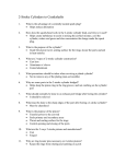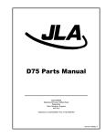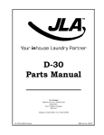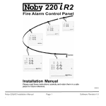
1
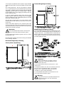
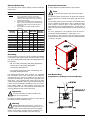
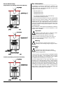
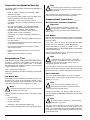
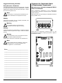
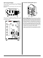
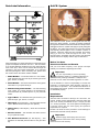
D20 (II) Installation
Manual
WARNING: For your safety the information in this manual must be followed to minimize the
risk of fire or explosion or to prevent property damage, personal injury or death.
— Do not store or use gasoline or other flammable vapors and liquids in the vicinity of this or
any other appliance.
— WHAT TO DO IF YOU SMELL GAS:
•
•
•
•
Do not try to light any appliance.
Do not touch any electrical switch; do not use any phone in your building.
Clear the room, building or area of all occupants.
Immediately call your gas supplier from a neighbor’s phone. Follow the gas
supplier’s instructions.
• If you cannot reach your gas supplier, call the fire department.
— Installation and service must be performed by a qualified installer, service agency or the
gas supplier.
JLA Limited
Meadowcroft Lane, Halifax Road – Ripponden
West Yorkshire, England HX6 4AJ
Telephone: 01422 822282 / Fax: 01422 824390
JLA Part No. 113197
Retain This Manual in a Safe Place for Future Reference
This product embodies advanced concepts in engineering, design, and safety. If this product is properly
maintained, it will provide many years of safe, efficient, and trouble free operation.
Only qualified technicians should service this equipment.
OBSERVE ALL SAFETY PRECAUTIONS displayed on the equipment or specified in the installation
manual included with the dryer.
The following “FOR YOUR SAFETY” caution must be posted near the dryer in a prominent location.
FOR YOUR SAFETY
Do not store or use gasoline or other flammable vapors
and liquids in the vicinity of this or any other appliance.
We have tried to make this manual as complete as possible and hope you will find it useful. The manufacturer
reserves the right to make changes from time to time, without notice or obligation, in prices, specifications,
colors, and material, and to change or discontinue models. The illustrations included in this manual may not
depict your particular dryer exactly.
IMPORTANT
For your convenience, log the following information:
D20
DATE OF PURCHASE ____________________________________________________ MODEL NO. _____________________
DISTRIBUTOR’S NAME ____________________________________________________________________________________
Serial Number(s) ________________________________________________________________________________________
______________________________________________________________________________________________________
______________________________________________________________________________________________________
Replacement parts can be obtained from your distributor or JLA. When ordering replacement parts, you can
FAX your order to JLA at 01422 824390 or telephone your order directly to the JLA Parts Department at
01422 822282. Please specify the dryer model number and serial number in addition to the description and
part number, so that your order is processed accurately and promptly.
“IMPORTANT NOTE TO PURCHASER”
Information must be obtained from your local gas supplier on the
instructions to be followed if the user smells gas. These instructions
must be posted in a prominent location near the dryer.
IMPORTANT
You must disconnect and lockout the electric
supply and the gas supply or the steam supply
before any covers or panels are removed from
the machine to allow access for cleaning,
adjusting, installation, or testing of any equipment
per OSHA standards.
Table of Contents
Safety Precautions .............................. 4
Specifications ...................................... 5
Installation Procedures ....................... 7
When discarding or storing your old clothes dryer,
remove the door.
Unpacking/Setting Up .................................................... 7
Location Requirements .................................................. 7
Dryer Enclosure Requirements ..................................... 7
Fresh Air Supply Requirements ..................................... 8
Exhaust Requirements .................................................. 8
Electrical Information ................................................... 10
Gas Information ........................................................... 12
Preparation for Operation/Start-Up ............................... 14
Preoperational Test ...................................................... 14
Preoperational Instructions .......................................... 14
Shutdown Instructions ................................................. 15
CAUTION
Dryer(s) should never be left unattended while in
operation.
Service ......................................................................... 15
Parts ............................................................................ 15
Please observe all safety precautions displayed
on the equipment and/or specified in the
installation manual included with the dryer.
Dryer must be installed in a location/environment,
which the ambient temperature remains between
40° F (4.44° C) and 130° F (54.44° C).
“Caution: Label all wires prior to disconnection
when servicing controls. Wiring errors can cause
improper operation.”
WARNING
Do not allow children to play on or in the
appliance. Close supervision of children is
necessary when the appliance is used near
children.
Under no circumstances should the dryer main
door switch, lint drawer/tray switch, or the heat
circuit devices ever be disabled.
Service/Parts Information ................. 15
Warranty Information ........................ 15
Returning Warranty Cards ........................................... 15
Warranty ...................................................................... 15
Routine Maintenance ......................... 15
Procedure for Functional Check
of Replacement Components ............ 16
Data Label Information...................... 18
S.A.F.E. System .................................. 18
The dryer must never be operated with any of the
back guards, outer tops, or service panels
removed. Personal injury or fire could result.
The dryer must never be operated without the lint
filter/screen in place, even if an external lint
collection system is used.
FOR YOUR SAFETY
Do not dry mop heads in the dryer. Do not use
dryer in the presence of dry cleaning fumes.
The dryers must not be installed or stored in
an area where it will be exposed to water
and/or weather.
The wiring diagram for the dryer is located
behind the front control panel.
ABBREVIATION _______________________________
D.M.S.
DSI
HVAC
in WC
L.C.D.
L.E.D.
OSHA
S.A.F.E.
UL
Drill Measurement Size
Direct Spark Ignition
Heating, Ventilating, and Air-Conditioning
Inches of Water Column
Liquid Crystal Display
Light Emitting Diode
Occupational Safety and Health Administration
Sensor Activated Fire Extinguishing System
Underwriters Laboratories
Safety Precautions __________________
Warning
!
For your safety, the information in this manual
must be followed to minimize the risk of fire or
explosion or to prevent property damage, personal injury,
or loss of life.
For personal safety, the dryer must be electrically grounded
in accordance with country, state, and local codes. For the
U.K., the following electrical and other local regulations must
be referred to:
• BS 7671:1992 (16th edition) IEE Wiring Regulations,
• National and Local Building Regulations
• Fire Authority Requirements
The dryer must never be operated with the back guard
removed. Personal injury or fire could result.
• Any relevant requirements of the Local Authority and
the Health & Safety Executive
Do not store or use gasoline or other flammable vapors and
liquids in the vicinity of this or any other appliance.
Note
!
Purchaser/user should consult the local gas supplier for
proper instructions to be followed in the event the user smells
gas. The instructions should be posted in a prominent
location.
Failure to electrically ground the dryer properly will
void the warranty.
Warning
!
Personal injury or fire could result should the dryer
main door switch, lint drawer/tray switch, or the
heat circuit devices ever be disabled.
What To Do If You Smell Gas:
• Do not try to light any appliance.
• Do not touch any electrical switch.
This dryer is not to be used in the presence of dry cleaning
solvents or fumes.
• Do not use any phone in your building.
Remove articles from the dryer as soon as the drying cycle
has been completed.
• Clear the room, building, or area of all occupants.
• Immediately call your gas supplier from a neighbor’s
phone. Follow the gas supplier’s instructions.
Warning
!
• If you cannot reach your gas supplier, call the fire
department.
Installation and service must be performed by a qualified
installer, service agency, or gas supplier.
Articles left in the dryer after the drying and cooling
cycles have been completed can create a fire
hazard.
Read and follow all caution and direction labels attached to
the dryer.
This dryer must be exhausted to the outdoors.
Although JLA produces a very versatile dryer, there are some
articles that, due to fabric composition or cleaning method,
should not be dried in it.
Warning
!
Dry only water washed fabrics. Do not dry articles
spotted or washed in dry cleaning solvents, a
combustible detergent, or “all purpose” cleaner. Explosion
could result.
Do not dry rags or articles coated or contaminated with
gasoline, kerosene, oil, paint, or wax. Explosion could
result.
Warning
!
You must disconnect and lockout the electric
supply and the gas supply or the steam supply
before any covers or panels are removed from the
machine to allow access for cleaning, adjusting,
installation, or testing of any equipment per OSHA
standards.
Important
!
Dryer must be installed in a location/environment,
which the ambient temperature remains between
40º F (4.44º C) and 130º F (54.44º C).
Do not dry mop heads. Contamination by wax or
flammable solvents will create a fire hazard.
Do not use heat for drying articles that contain plastic,
foam, sponge rubber, or similarly textured rubber
materials. Drying in a heated tumbler may damage
plastics or rubber and may be a fire hazard.
A program should be established for the inspection and
cleaning of lint in the exhaust ductwork and area around the
back of the dryer. The frequency of inspection and cleaning
can best be determined from experience at each location.
Warning
!
4
The collection of lint in the exhaust ductwork can
create a potential fire hazard.
JLA Limited
113197-5
Specifications _____________________________________________________________________
MAXIMUM CAPACITY (DRY WEIGHT)
20 lbs
9 kg
BASKET (TUMBLER) DIAMETER
25-3/4”
65.4 cm
24”
60.95 cm
BASKET (TUMBLER) VOLUME
7.5 cu ft
0.21 cu m
BASKET (TUMBLER) MOTOR
1/4 hp
0.19 kW
BLOWER MOTOR
1/8 hp
0.09 kW
CABINET WIDTH
27”
68.6 cm
CABINET DEPTH
30-5/8”
77.78 cm
CABINET HEIGHT
41-1/4”
104.78 cm
4”
10.2 cm
40,000 Btu/hr
11.71 kW
AIRFLOW @ 60 Hz
230 cfm
6.51 cmm
AIRFLOW @ 50 Hz
210 cfm
5.85 cmm
BASKET (TUMBLER) DEPTH
EXHAUST CONNECTION
HEAT INPUT
Electric
Gas
WATER CONNECTION
3/4” M.N.P.T.
VOLTAGE AVAILABLE
120v, 208v, 240v / 60 Hz / 1ø
240v / 50 Hz / 1ø
NET WEIGHT
246-1/2 lbs
INLET PIPE CONNECTION
111.8 kg
3/8” M.N.P.T.
VOLTAGE AVAILABLE
208v, 240v / 60 Hz / 1ø
240v / 50 Hz / 1ø
380v, 400v, 416v / 50 Hz / 3ø
NET WEIGHT
239-1/2 lbs
108.6 kg
Oven Size
Voltage
kW
Btu/hr
kcal/hr
208
4.1
13,993
3,526
208
6.1
20,819
5,246
230
5.0
17,065
4,300
230
7.4
25,255
6,364
240
5.4
18,430
4,644
240
8.1
27,644
6,966
380
6.8
23,208
5,848
400
7.5
25,597
6,450
416
8.1
27,644
6,966
Shaded areas are stated in metric equivalents
!
1/27/04
Note
JLA reserves the right to make changes in specifications at any time without notice or obligation.
113197-5
Telephone 01422 822282
5
6
JLA Limited
113197-5
Installation Procedures _____________
Installation should be performed by competent technicians
in accordance with country, state, and local codes. For the
U.K., the following electrical and other local regulations must
be referred to:
Dryer must be exhausted to the outdoors as noted in this
manual (refer to Exhaust Requirements).
Dryer must be located in an area where correct exhaust venting
can be achieved as noted in this manual (refer to Exhaust
Requirements).
Important
• BS 7671:1992 (16th edition) IEE Wiring Regulations,
!
• National and Local Building Regulations
• Fire Authority Requirements
• Any relevant requirements of the Local Authority and
the Health & Safety Executive
All plumbing connections, components, materials, and
workmanship must conform with country, state, and local
codes. For the U.K., the following publication and other local
regulations must be referred to:
The dryer must be installed with a proper exhaust duct
connection to the outside.
The dryer must be installed with provisions for adequate
combustion and make-up air supply.
Caution
!
This dryer produces combustible lint and must be
exhausted to the outdoors. Every 6 months,
inspect the exhaust ducting and remove any lint buildup.
• BS 5440 parts 1 & 2
• IGEM publication IM/5
• IGEM publication IM/2
• Any relevant requirements of the Local Authority
and the Health & Safety Executive
Unpacking/Setting Up _______________
Remove protective shipping material (i.e., plastic wrap and
optional shipping box) from the dryer.
Important
!
Dryer should be located where a minimum
amount of exhaust duct will be necessary.
Dryer must be transported and handled in an
upright position at all times.
The dryer can be moved to its final location while still attached
to the skid or with the skid removed. To remove the skid from
the dryer, locate and remove the 2 bolts securing the base of
the dryer to the wooden skid.
Important
!
Dryer must be installed in a location/environment,
which the ambient temperature remains between
40º F (4.44º C) and 130º F (54.44º C).
Dryer Enclosure Requirements ______
Note
!
Allowances must be made for opening the control
door.
Air considerations are important for proper and efficient
operation.
Commercial Type II
With the skid removed, to make it easier to slide the dryer into
its final position, slightly lower all 4 leveling legs, so that the
dryer will slide on the legs instead of the base frame.
Location Requirements ______________
Before installing the dryer, be sure the location conforms to
local codes and ordinances.
The dryer must be installed on a sound level floor capable of
supporting its weight. Carpeting must be removed from the
floor area that the dryer is to rest on.
The dryer must not be installed or stored in an area where it
will be exposed to water and/or weather.
The dryer is for use in noncombustible locations.
Provisions for adequate air supply must be provided as noted
in this manual (refer to Fresh Air Supply Requirements).
Clearance provisions must be made from noncombustible
construction as noted in this manual (refer to Dryer Enclosure
Requirements).
Provisions must be made for adequate clearances for
servicing and for operation as noted in this manual (refer to
Dryer Enclosure Requirements).
113197-5
6-inch (15.24 cm) minimum, 24-inches (60.96 cm) is suggested for ease of
maintenance.
Dryers may be positioned sidewall to sidewall. It is suggested
that the dryer be positioned about 2 feet (0.61 meters) away
from the nearest obstruction for ease of installation,
maintenance, and service (to be measured from the back
guard). Refer to the illustration above for details.
Telephone 01422 822282
7
Domestic Type I
It is not necessary to have a separate make-up air opening
for each dryer. Common make-up air openings are
acceptable. However, they must be set up in such a manner
that the make-up air is distributed equally to all the dryers.
EXAMPLE: For a bank of 4 dryers, 2 unrestricted openings
measuring 8-inches by 10-inches (20.4 cm by 25.4 cm) are
acceptable.
Allowances must be made for remote or constricting
passageways or where dryers are located at excessive
altitudes or predominantly low pressure areas.
A = 8-Inches (20.4 cm)
B = 10-Inches (25.4 cm)
Important
!
If a closet door is installed: Unobstructed air openings are
required. The air openings shall be located 3-inches (7.62
cm) from the lower opening (above floor level) and upper
opening (below ceiling). The total free area of the air openings
in the door shall not be less than 96 inches2 (619.3536
centimeters2). Louvered doors with equivalent air openings
are acceptable.
Make-up air must be provided from a source free
of dry cleaning solvent fumes. Make-up air that is
contaminated by dry cleaning solvent fumes will result in
irreparable damage to the motors and other dryer
components.
Note
!
Component failure due to dry cleaning solvent
fumes will void the warranty.
Fresh Air Supply Requirements _____
Exhaust Requirements ______________
When the dryer is operating, it draws in room air, heats it,
passes this air through the tumbler, and exhausts it out of the
building. Therefore, the room air must be continually
replenished from the outdoors. If the make-up air is
inadequate, drying time and drying efficiency will be adversely
affected. Ignition problems and sail switch “fluttering”
problems may result, as well as premature motor failure from
overheating. The dryer must be installed with provisions for
adequate combustion and make-up air supply.
Do not use a nonmetal flexible vent or a metal vent that is
smaller than 4-inches (10.2 cm) in diameter or exhaust hoods
with magnetic latches.
Air supply (make-up air) must be given careful consideration
to ensure proper performance of each dryer. As a general
rule, an unrestricted air entrance from the outdoors
(atmosphere) measuring a minimum size of 5-inches by
8-inches (12.7 cm x 20.4 cm) is required for each dryer. (Based
on 1 inch2 [6.4516 cm2] per 1,000 Btu [251.9958 kcal].)
Do not exhaust dryer into a chimney, furnace, cold air vent,
attic, crawl space, or any other vent used for venting.
Do not install flexible vent in enclosed walls, ceilings, or floors.
!
Observe all governing codes and ordinances.
Exhaust your dryer to the outside. Moisture and lint indoors
may cause:
To compensate for the use of registers or louvers used over
the openings, this area must be increased by approximately
33%. Make-up air openings should not be located in an area
directly near where exhaust vents exit the building.
8
Important
JLA Limited
• Lint to gather around the dryer where it can be fuel for a
fire.
• Moisture damage to woodwork, furniture, paint,
wallpaper, carpet, etc.
• Housecleaning problems and health problems.
113197-5
A 4-inch (10.2 cm) diameter vent is required. A rigid or flexible
metal vent must be used. Do not use a plastic or a foil covered
vent.
Vertical Single Dryer Venting
Use a heavy metal vent. Do not use a plastic or metal foil
vent. A rigid metal vent is recommended to prevent crushing
and kinking. A flexible metal vent must be fully extended and
supported when the dryer is in its final position. Remove
excess flexible vent to avoid sagging and kinking that may
result in reduced airflow.
If using an existing exhaust system, clean lint from entire
length of system. Make sure exhaust hood is not plugged
with lint. Replace any vinyl or metallized plastic foil vent with
rigid metal or flexible metal vent.
Use duct tape to seal all joints. Do not use screws or other
fastening devices that extend into the interior of the vent to
secure vent.
Service check: Back pressure in any exhaust system used
must be no less than 0 and must not exceed 0.6 in WC (1.49
mb) measured with an incline manometer at the point that
exhaust vent connects to the dryer.
Multiple Dryer (Common) Venting
Important
!
It is recommended that exhaust or booster fans
not be used in the exhaust ductwork system.
For flue systems and ventilation systems in the U.K., refer to
BS 5440 parts 1 & 2.
If it is not feasible to provide separate exhaust ducts for each
dryer, ducts from individual dryers may be channeled into a
“common main duct.” The individual ducts should enter the
bottom or side of the main duct at an angle not more than 45°
in the direction of the flow and should be spaced at least
27-inches (68.58 cm) apart.
Recommended horizontal and vertical venting are illustrated
in the following diagrams.
Horizontal Single Dryer Venting
4-Inch (10.16 cm) Ducting
Important
!
When exhausted into a multiple (common)
exhaust line, a back draft damper must be
installed at each dryer duct.
No more than 4 dryers should be connected to 1 main
common duct.
For extended ductwork runs, the cross-sectional area of the
duct can only be increased to extent. For extended
ductwork runs, a professional HVAC firm should be
consulted for proper venting information.
It is recommended that exhaust or booster fans not be
used in the exhaust ductwork system.
Warning
!
The dryer must never be operated without the lint
filter/screen in place, even if an external lint
collection system is used.
113197-5
Telephone 01422 822282
9
Important
Important Venting Requirements
!
Failure to comply with these codes or ordinances,
and/or the requirements stipulated in this manual
can result in personal injury or component failure.
• Ductwork size and installation should be done by a
qualified professional.
• This dryer must be exhausted to the outdoors.
• Ductwork should be routed as short as possible to the
outdoors with as few elbows as possible.
Each circuit must be connected to an independently
protected branch circuit.
Use only copper conductor cable of proper ampacity and
insulation in accordance with electric codes for making
service connections.
• Avoid 90° turns, use 30° or 45° turns instead.
• The inside of the ductwork should be as smooth as
possible with no projections from fasteners.
A separate circuit servicing each dryer must be provided.
• Ducts added should overlap the duct to which it is to
be connected.
Electrical Service Specifications
• All ducts should be taped to prevent moisture and lint
from escaping into the building.
• Inspection or clean out doors should be installed
throughout strategic points in the ductwork for periodic
inspection and cleaning.
• Whenever the ductwork passes through combustible
materials, the opening must be 2-inches (5.08 cm)
larger than the duct (all the way around). The duct
must be centered within this opening.
• The outside of the ductwork must be protected from
the weather. A 90° elbow must be used for horizontal
run and when vertically through a roof by using a 180°
turn to point the opening downward. The distance
between the exhaust duct and the nearest obstruction
(i.e. roof or ground) must be twice the diameter of the
duct.
Important
!
The wire size must be properly sized to handle the
related current.
The dryer must be connected to the electric service/supply
shown on the dryer data label.
Note
!
JLA reserves the right to make changes in
specifications at any time without notice or
obligation.
Component failure due to improper voltage application will
void the warranty.
Gas Models Only
ELECTRICAL SERVICE SPECIFICATIONS (PER DRYER)
• Do not use screens, louvers, or caps on the outside
opening of the exhaust ductwork.
NOTES:
A.
• Exhaust back pressure measured by a manometer at
the dryer exhaust duct area must be no less than 0
and must not exceed 0.6 in WC (1.49 mb).
B.
• Exhaust ductwork outlets should not be located in an
area directly where the make-up air openings are
located.
C.
Electrical Information _______________
Electrical Requirements
It is your responsibility to have all electrical connections made
by a properly licensed and competent electrician to ensure
that the electrical installation is adequate and conforms to
local and country regulations or codes. For the U.K., the
following electrical and other local regulations must be
referred to:
When fuses are used they must be dual element, time
delay, current limiting, class RK1 or RK5 ONLY.
Calculate/determine correct fuse value, by applying
either local and/or National Electrical Codes to listed
appliance amp draw data.
Circuit breakers are thermal-magnetic (industrial) motor
curve type ONLY. For others, calculate/verify correct
breaker size according to appliance amp draw rating
and type of breaker used.
Circuit breakers for 3-phase (3Ø) dryers must be
3-pole type.
SERVICE
VOLTAGE
PHASE
120
208
230
240
1ø
1ø
1ø
1ø
APPROX.
WIRE
AMP DRAW CIRCUIT
SERVICE
BREAKER
2
2
2
2
60 Hz
50 Hz
8.4
4.3
--4.7
----4.8
5.0
15
15
15
15
3/9/04
• BS 7671:1992 (16th edition) IEE Wiring Regulations,
• National and local Building Regulations
• Fire Authority Requirements
• Any relevant requirements of the Local Authority and
the Health & Safety Executive
Note
!
Component failure due to improper installation
will void the warranty.
The use of aluminum wire will void the warranty.
10
JLA Limited
113197-5
Electric Models Only
Electrical Connections
The connecting wires must be properly sized to handle the
rated current.
A wiring diagram is located inside the control panel.
ELECTRICAL SERVICE SPECIFICATIONS (PER DRYER)
NOTES:
A.
B.
C.
When fuses are used they must be dual element, time
delay, current limiting, class RK1 or RK5 ONLY.
Calculate/determine correct fuse value, by applying
either local and/or National Electrical Codes to listed
appliance amp draw data.
Circuit breakers are thermal-magnetic (industrial) type
ONLY. For others, calculate/verify correct breaker size
according to appliance amp draw rating and type of
breaker used.
Circuit breakers for 3-phase (3Ø) dryers must be
3-pole type.
SERVICE
VOLTAGE
PHASE
208 (4.1 kW)
208 (6.1 kW)
230 (5.0 kW)
230 (7.4 kW)
240 (5.4 kW)
240 (8.1 kW)
380 (6.8 kW)
400 (7.5 kW)
416 (8.1 kW)
1ø
1ø
1ø
1ø
1ø
1ø
3ø
3ø
3ø
APPROX.
WIRE
AMP DRAW CIRCUIT
SERVICE
BREAKER
2
2
2
2
2
2
4
4
4
60 Hz
50 Hz
24.0
33.6
--27.2
38.5
----
--26.0
36.5
27.5
38.8
14.9
15.6
16.2
30
40
30
45
30
45
20
20
20
!
Note
A circuit servicing each dryer must be provided.
The electrical input connections on all dryers are made into
the rear service box, located at the upper right area of the
dryer.
If local codes permit, power to the dryer can be made by the
use of a flexible UL listed power cord or pigtail (wire size
must conform to rating of dryer), or the dryer can be hard
wired directly to the service breaker panel. In both cases, a
strain relief must be installed where the wiring enters the
dryer.
For U.K. applications, the appliance must be wired in
accordance with BS ENG0335-1; 1995 clause 7.12.
The means for disconnection from the supply must be
incorporated into wiring having a minimum contact separation
of 3.0mm in all poles.
3/9/04
Grounding
A ground (earth) connection must be provided and installed
in accordance with country, state, and local codes. For the
U.K., the following electrical and other local regulations must
be referred to:
• BS 7671:1992 (16th edition) IEE Wiring Regulations,
• National and Local Building Regulations
• Fire Authority Requirements
• Any relevant requirements of the Local Authority and
the Health & Safety Executive
For added personal safety, when possible, it is suggested
that a separate ground wire (size per local codes) be
connected from the ground connection of the dryer to a
grounded cold water pipe. Do not ground to a gas pipe or hot
water pipe. The grounded cold water pipe must have
metal-to-metal connection all the way to the electrical ground.
If there are any nonmetallic interruptions, such as a meter,
pump, plastic, rubber, or other insulating connectors, they
must be jumped out with a wire (size per local codes) and
securely clamped to bare metal at both ends.
Gas Models Only
Single-Phase (1ø) Wiring Connections/Hookup
Important
!
For personal safety and proper operation, the
dryer must be grounded.
Provisions are made for ground connection in each dryer at
the electrical service connection area.
Warning
!
Electrical Grounding Instructions – This dryer is
equipped with a 3-prong (grounding) plug for your
protection against shock hazard and should be plugged
directly into a properly grounded 3-prong receptacle. Do
not cut or remove the grounding prong from this plug.
113197-5
Telephone 01422 822282
11
Electric Models Only
Single-Phase (1ø) Wiring Connections/Hookup
Gas Information ______________________
All plumbing connections, components, materials, and
workmanship must conform with country, state, and local
codes. For the U.K., the following publication and other local
regulations must be referred to:
• BS 5440 parts 1 & 2
• IGEM publication IM/5
• IGEM publication IM/2
• Any relevant requirements of the Local Authority
and the Health & Safety Executive
The dryer must be disconnected from the gas supply piping
system during any pressure testing of that system at test
pressures in excess of 1/2 psig (3.5 kPa). The dryer must be
isolated from the gas supply piping system by closing an
external manual shutoff valve during any pressure test of the
gas supply system at test pressures equal to or less than
1/2 psig (3.5 kPa).
Before installation, check that the local distribution conditions,
nature of gas and pressure, and the adjustment of the
appliance are compatible.
Important
!
Failure to comply with codes or ordinances, and/or
requirements in this manual, can result in
personal injury and improper operation of the dryer.
Failure to isolate or disconnect the dryer from supply as
noted can cause irreparable damage to the gas valve,
which will void the warranty.
Warning
!
Fire or explosion could result due to failure of
isolating or disconnecting the gas supply as noted.
Gas Supply
Note
!
Undersized gas piping will result in ignition
problems, slow drying, increased use of energy,
and can create a safety hazard.
3-Phase (3ø) Wiring Connections/Hookup
The dryer must be connected to the type of heat/gas indicated
on the dryer data label. If this information does not agree
with the type of gas available, do not operate the dryer. Contact
the distributor who sold the dryer or contact JLA.
The input ratings shown on the dryer data label are for
elevations up to 2,000 feet (609.6 meters), unless elevation
requirements of over 2,000 feet (609.6 meters) were specified
at the time the dryer order was placed with the factory. The
adjustment or conversion of dryers in the field for elevations
over 2,000 feet (609.6 meters) is made by changing each
burner orifice. If this conversion is necessary, contact the
distributor who sold the dryer or contact JLA.
12
JLA Limited
113197-5
Important
!
Important
Any burner changes must be made by a qualified
professional.
This gas dryer is not provided with an internal gas supply
shutoff and an external gas supply shutoff must be
provided.
Technical Gas Data
Gas Specifications
The gas supply line to each dryer must be a
minimum of 3/8” (9.5 mm). Do not reduce this
pipe size requirement.
The size of the main gas supply line (header) will vary
depending on the distance this line travels from the gas
meter. Specific information regarding supply line size should
be determined by the gas supplier.
Note
TYPE OF GAS
NATURAL – G20
Manifold Pressure*
9.0 mb
Supply Pressure
20 mb
* Measured at outlet side of gas valve pressure tap when gas valve is on.
Gas Connections
Inlet connection __________
Inlet supply size __________
Btu/hr input (per dryer) _____
Gas Rate _______________
3/8” M.P.T.
3/8” Diameter Pipe (min)
40,000 (11.71 kW)
1.120 M3/H
!
Undersized gas supply piping can create a low or
inconsistent pressure, which will result in erratic
operation of the burner ignition system.
Consistent gas pressure is essential at all gas connections.
It is recommended that a 1/2” (12.7 mm) pipe gas loop be
installed in the supply line servicing a bank of dryers. An
in-line pressure regulator must be installed in the gas supply
line (header) if the (natural) gas pressure exceeds 12.0 in
WC (29.9 mb) pressure.
A 1/8” N.P.T. plugged tap, accessible for a test gauge
connection, must be installed in the main gas supply line
immediately upstream of each dryer.
!
Natural Gas
Regulation is controlled by the dryer’s gas valve’s internal
regulator. Incoming supply pressure must be consistent
between a minimum of 6.0 in WC (14.92 mb) and a maximum
of 12.0 in WC (29.9 mb) pressure.
TYPE OF GAS
Natural
Btu/hr
Rating
kW
Rating
Qty.
D.M.S.*
Part No.
40,000
11.71
1
#31
140868
Shaded area is stated in metric equivalent
Note
Gas pressure to the burner should be checked at
the time of dryer commissioning by a gas
competent technician and adjusted if necessary.
Important
!
Access cover to the gas pressure regulator
adjustment screw must be reinstalled and sealed
after adjusting pressure to detect tampering. Be certain
that the regulator adjustment access cover is sealed upon
completion of dryer commissioning.
The dryer and its individual shutoff valve must be
disconnected from the gas supply piping system during any
pressure testing of that system at test pressures in excess
of 1/2 psig (3.5 kPa).
Pipe joint compounds that resist the action of natural gas
must be used.
* D.M.S. equivalent: Natural Gas – #31 = 0.1200” (3.048 mm).
Piping Connections
All plumbing connections, components, materials, and
workmanship must conform with country, state, and local
codes. For the U.K., the following publication and other local
regulations must be referred to:
• BS 5440 parts 1 & 2
• IGEM publication IM/5
• IGEM publication IM/2
• Any relevant requirements of the Local Authority
and the Health & Safety Executive
The dryer is provided with a 3/8” M.P.T. inlet pipe connection,
located at the left side of the base of the dryer when viewing
from the rear. The minimum pipe size (supply line) to the
dryer is 3/8” diameter. For ease in servicing, the gas supply
line of each dryer must have its own shutoff valve.
113197-5
!
Test all connections for leaks by brushing on a soapy water
solution (liquid detergent works well).
!
Note
The dryer must be isolated from the gas supply
piping system by closing its individual manual
shutoff valve during any pressure test of the gas supply
system at test pressures equal to or less than 1/2 psig (3.5
kPa).
A water column test pressure of 3.5 in WC (8.7 mb) for
natural gas is required at the gas valve pressure tap of
each dryer for proper and safe operation.
!
Warning
Never test for leaks with a flame!!!
Telephone 01422 822282
13
Preparation for Operation/Start-Up _
The following items should be checked before attempting to
operate the dryer:
• Read all “caution,” “warning,” and “direction” labels
attached to the dryer.
• Check incoming supply voltage to be sure that it is the
same as indicated on the dryer data label.
• Gas Models – check to ensure that the dryer is
connected to the type of heat/gas indicated on the dryer
data label.
• Gas and Electric Models – the sail switch damper
assembly was installed and adjusted at the factory
prior to shipping. However, each sail switch
adjustment must be checked to ensure that this
important safety control is functioning.
Note
!
If computer program changes are required, refer to
the computer programming section of the manual
supplied with the dryer.
The dryer should be operated through 1 complete cycle to
ensure that all components are functioning properly.
Preoperational Instructions _________
Microprocessor Controller (Computer)
Important
!
For more detailed information regarding the
microprocessor controller (computer) on your
dryer, refer to the microprocessor user’s manual included
with the dryer.
Coin Models
• Check bolts, nuts, screws, terminals, and fittings for
tightness.
• Gas Models – be sure that all gas shutoff valves are in
the open position.
When the microprocessor controller (computer) is in the ready
state, the L.C.D. screen will display “Ready, Insert $XX.XX
(amount) to Start”.
• Check that the back guard panel and the electrical box
cover have been replaced.
Insert coin(s). Once the correct “Amount to Start” has been
inserted, the L.C.D. will display “Select Temperature”.
• Check the lint drawer/tray to ensure that it is closed
and secured in place.
Select temperature by pressing “HI,” “MED,” or “LO”. The
cycle will start and the L.C.D. will display the Dry Cycle selected
and the remaining time.
• Rotate the tumbler/drum by hand to be sure it moves
freely.
The dryer will continue through the drying and cooling cycles,
until the vended time has expired.
• Check terminals and fittings for security.
Preoperational Test _________________
All dryers are thoroughly tested and inspected before leaving
the factory. However, a preoperational test should be
performed before the dryer is publicly used. It is possible
that adjustments have changed in transit or due to marginal
location (installation) conditions.
Turn on electric power to the dryer.
Refer to the Operating Instructions for starting your particular
model dryer.
!
To stop the dryer, open main door or press the
pause key. Continuation of the cycle will resume
only after the door has been closed and any of the 3
temperature selections is pressed.
Upon completion of the drying and cooling cycles, the tone
(buzzer) will sound and the dryer will go into the Anti-Wrinkle
Mode for 99 minutes, or until the main door has been opened.
Non-Coin Models
The L.E.D. display reads “READY” (no cycle in progress).
Gas Models Only
When a gas dryer is first started (during initial start-up), it has
a tendency not to ignite on the first ignition attempt. This is
because the gas supply piping is filled with air, so it may take
a few minutes for the air to be purged from the lines.
Note
!
Note
During the purging period, check to be sure that all
gas shutoff valves are open.
Make a complete operational check of all safety related
circuits:
Press the letter on the keypad corresponding to the cycle
desired (i.e., key “D”).
Note
!
“0-40” will require the “Start/Enter” key to be
pressed after the number is selected in order to
accept the selection and start drying.
The dryer will then start. (I.E., blower, tumbler, and heat.)
The L.E.D. display will read MANUAL DRYING CYCLE D, 00:00
MIN REMAIN.
• Door Switch(es)
Note
• Hi-Limit Thermostats
!
• Cycling Thermostat
• Sail Switch – Gas and Electric Models Only
Make a complete operational check of all operating controls.
14
Press and hold the “Up Arrow” to view the tumbler
temperature at any time.
The dryer can be stopped at any time by pressing the
“Stop/Clear” key, at this time the dryer will go into a cycle
pause. If the “Stop/Clear” key is pressed again at this point,
the cycle that was in progress will be cancelled and returned
to the “READY” state.
JLA Limited
113197-5
Press and hold the “Down Arrow” to view the tumbler RPM.
When the programmed drying time has expired, the Phase 7
non-coin microprocessor controller (computer) will proceed
into the Cool Down Cycle.
Once the Cool Down Cycle begins at the end of the heat
cycle, the L.E.D. display will read COOL DOWN TEMP
___/___ MINUTES remaining. At the end of the heat cycle,
the dryer will shut off the heat and continue to run the blower
and tumbler until the Cool Down Time or temperature is
reached.
Shutdown Instructions ______________
If the dryer is to be shutdown (taken out of service) for a
period of time, the following must be performed:
Discontinue power to the dryer either at the external disconnect
switch or the circuit breaker.
Discontinue the Heat Supply
Returning Warranty Cards
Before any dryer leaves the factory test area, a warranty card
is placed on the back side of the main door glass. These
warranty cards are intended to serve the customer where we
record the individual installation date and warranty information
to better serve you, should you file a warranty claim.
If a warranty card did not come with your dryer, contact the JLA
Warranty Department.
Important
!
A separate warranty card must be completed and
returned for each individual dryer.
Note
!
Be sure to include the installation date when
returning the warranty card(s).
Warranty
Gas Models – discontinue the gas supply.
Shut off external gas supply shutoff valve.
Service/Parts Information ___________
Service
Service must be performed by a qualified trained technician,
service agency, or gas supplier. If service is required, contact
the distributor from whom the JLA equipment was purchased.
If the distributor cannot be contacted or is unknown, contact
the JLA Service Department for a distributor in your area.
Note
!
When contacting the JLA Service Department, be
sure to give them the correct model number and
serial number so that your inquiry is handled in an
expeditious manner.
Parts
Replacement parts should be purchased from the distributor
from whom the JLA equipment was purchased. If the
distributor cannot be contacted or is unknown, contact the
JLA Parts Department for a distributor in your area. Parts
may also be purchased directly from the factory by calling the
JLA Parts Department at 01422 822282 or you may FAX in
your order at 01422 824390.
For a copy of the JLA commercial warranty covering your
particular dryer(s), contact the distributor from whom you
purchased the equipment and request a dryer warranty form.
If the distributor cannot be contacted or is unknown, warranty
information can be obtained from JLA by contacting the JLA
Warranty Department.
Note
!
Whenever contacting the JLA factory for warranty
information, be sure to have the dryer’s model
number and serial number available so that your inquiry
can be handled in an expeditious manner.
Routine Maintenance ________________
A program and/or schedule should be established for
periodic inspection, cleaning, and removal of lint from various
areas of the dryer, as well as throughout the ductwork system.
The frequency of cleaning can best be determined from
experience at each location. Maximum operating efficiency
is dependent upon proper air circulation. The accumulation
of lint can restrict this airflow. If the guidelines in this section
are met, a JLA dryer will provide many years of efficient, trouble
free, and most importantly, safe operation.
Warning
!
Note
!
Warranty Information ________________
When ordering replacement parts from the
distributor or JLA be sure to give them the correct
model number and serial number so that your parts order
can be processed in an expeditious manner.
Lint from most fabrics is highly combustible. The
accumulation of lint can create a potential fire
hazard.
Keep dryer area clear and free from combustible materials,
gasoline, and other flammable vapors and liquids.
Note
!
Suggested time intervals shown are for average
usage, which is considered 6 to 8 operational
(running) hours per day.
Important
!
Dryer produces combustible lint and must be
exhausted to the outdoors. Every 6 months,
inspect the exhaust ducting and remove any lint buildup.
113197-5
Telephone 01422 822282
15
Procedure for Functional Check
of Replacement Components _______
Suggested Cleaning Schedule
Every Second or Third Load
Clean the lint drawer/tray every second or third load. A clogged
lint drawer/tray will cause poor dryer performance. The lint
drawer/tray is located on the lower front of the dryer. Inspect
lint screen and replace if torn.
Note
!
The frequency of cleaning the lint drawer/tray can
best be determined from experience at each
Microprocessor Controller (Computer) Board
Phase 7 Coin Models
Upon completing installation of the replacement
microprocessor controller (computer) board, reestablish
power to the dryer.
Start the drying cycle by pressing any temperature selection
keys (HI, MED, or LO).
location.
Weekly
Clean lint accumulation from lint chamber, thermostat, and
temperature hi-limit sensor area.
Warning
!
To avoid the hazard of electrical shock,
discontinue electrical supply to the dryer.
90 Days
Inspect and remove lint accumulation in customer furnished
exhaust ductwork system from dryer’s internal exhaust
ducting.
Warning
!
Verify that the applicable indicator lights on the
microprocessor controller (computer) board are lit. (Refer to
the illustration below.)
The accumulation of lint in the exhaust ductwork
can create a potential fire hazard.
Do not obstruct the flow of combustion and ventilation air.
Note
!
When cleaning the dryer cabinet(s), avoid using
harsh abrasives. A product intended for the
cleaning of appliances is recommended.
Notes ______________________________
___________________________________
___________________________________
___________________________________
___________________________________
___________________________________
___________________________________
___________________________________
___________________________________
___________________________________
___________________________________
___________________________________
___________________________________
___________________________________
16
JLA Limited
113197-5
Phase 7 Non-Coin Models
For Models with DSI Module (Type I)
Upon completing installation of the replacement
microprocessor controller (computer) board, reestablish
power to the dryer.
Start the drying cycle by pressing any of the preset cycles in
letters A-F.
Verify that the applicable indicator lights on the
microprocessor controller (computer) board are lit. (Refer to
the illustration below.)
Theory of Operation: Start the drying cycle. When the
gas burner ignites within the chosen trial for ignition time
(6-seconds), the flame sensor detects gas burner flame and
signals the DSI module to keep the gas valve open as long
as there is a call for heat. The DSI module will “LOCKOUT” if
the gas burner flame is not sensed at the end of the trial for
ignition period. The trial for ignition period will be repeated
for a total of 3 retries/trials (the initial try and 2 more retries/
trials). If the flame is not sensed at the end of the third retry/
trial (inter-purge period of 30-seconds) the DSI module will
“LOCKOUT” (L.E.D. diagnostic indicator flashes).
A steady L.E.D. indicator indicates normal operation. No L.E.D.
indicator indicates a power or an internal failure has occurred.
113197-5
Telephone 01422 822282
17
Data Label Information ______________
S.A.F.E. System ______________________
The exclusive S.A.F.E. system will extinguish fires that may
start in the drying tumbler. A series of sensors positioned
throughout the tumbler and interfaced with the microprocessor
will trigger the S.A.F.E. system water jet(s) to quickly extinguish
the flames. The water jet(s) remain on for 2 minutes and will
automatically activate again if a fire condition remains or
reignites. While the water jet(s) are activated, the tumbler
will jog to move the water throughout the load. The
microprocessor will display that the system was activated
and will continue to display until the dryer is attended to.
When contacting JLA, certain information is required to ensure
proper service/parts information from JLA. This information
is on the data label that is affixed to the rear upper left back
area of the dryer, which can be viewed either through the
openings in the dryer’s back panel/guard, or by removing
this back panel/guard. When contacting JLA, please have
the model number and serial number available.
1. Model Number – The model number is a JLA number,
which describes the size of the dryer and the type of heat
(gas, electric, or steam).
2. Serial Number – The serial number allows JLA to gather
information on your particular dryer.
3. Manufacturing Code Number – The manufacturing
code number is a number issued by the manufacturer,
which describes all possible options on your particular
model.
4. Type of Heat – This describes the type of heat for your
particular dryer: gas, electric, or steam.
5. Heat Input (For Gas Dryers) – This describes the heat
input in British Thermal Units per Hour (Btu/hr).
6. Orifice Size (For Gas Dryers) – Gives the number drill
size used.
7. Electric Service – This describes the electric service
for your particular model.
8. Gas Manifold Pressure (For Gas Dryers) – This
describes the manifold pressure taken at the gas valve
tap.
18
Before You Start
Check Local Codes and Permits
Call your local water company or the proper municipal
authority for information regarding local codes.
Important
!
It is your responsibility to have all plumbing
connections made by a qualified professional to
ensure that the plumbing installation is adequate and
conforms to local, state, and federal regulations or codes.
It is the installer’s or owner’s responsibility to see that the
necessary or required water, water pressure, pipe size, or
connections are provided. The manufacturer assumes no
responsibility if the S.A.F.E. system is not connected, installed,
or maintained properly.
Installation
Requirements
The inlet water connection to the dryer is a 3/4” M.P.T., the
S.A.F.E. system must be supplied with a minimum water pipe
size of 1/2” and be provided with 40 psi +/- 20 psi (2.75 bar
+/- 1.37 bar) of pressure. For use of optional manual bypass,
a second source with the same piping and pressure
requirements is required.
Flexible 1/2 feeds must be provided to avoid damage to
electric water solenoid valve by vibration.
Important
!
Flexible supply line/coupling must be used.
Solenoid valve failure due to hard plumbing
connections will void warranty.
JLA Limited
113197-5
If the rear area of the dryer, or the water supply is located in an
area where it will be exposed to cold/freezing temperatures,
provisions must be made to protect these water lines from
freezing.
!
Warning
If the water in the supply line or water solenoid
valve freezes, the S.A.F.E. system will be
inoperative!!
!
Important
Appliance is to be connected to the water mains
using a new hose set and the old hose set should
not be reused.
Water Connections
The water connection is made to the 3/4” M.P.T. hex bushing
of the electric water solenoid valve, located at the rear upper
midsection of the dryer (refer to the photo). The water solenoid
valve has a 3/8” M.P.T. connection supplied with a 3/4” M.P.T.
hex bushing to provide the minimum 1/2” supply (feed) line.
Flexible supply line/coupling must be used in an effort to
avoid damaging the electric water solenoid valve.
!
Important
Flexible supply line/coupling must be used.
Solenoid valve failure due to hard plumbing
connections will void warranty. It is recommended that a
filter or strainer be installed in the water supply line.
Typical Water Supply
113197-5
Telephone 01422 822282
19
Warning
Optional Manual Bypass
Provisions are made in the dryer’s S.A.F.E. system for the
installation of an optional manual bypass. Depending on
the model dryer, the connections for the manual bypass are
made at the “T” or “cross” fitting, located in the outlet side of
the water solenoid valve. The use and connections of this
manual bypass are at the option or discretion of the owner.
The water connection for the manual bypass is made to the
“T” or “cross” fitting, which has a 3/8” F.P.T. and a coupling
must be used to provide the minimum 1/2” supply (feed) line.
If the rear area of the dryer, or the water supply is located in an
area where it will be exposed to cold/freezing temperatures,
provisions must be made to protect these water lines from
freezing.
!
If the water in the supply line or water solenoid
valve freezes, the S.A.F.E. system will be
inoperative!!
The manual ball cock shutoff valve must be located outside
of the dryer at a distance from the dryer where it is easily
accessible.
Electrical Requirements
No independent external power source or supply connection
is necessary. The 24 volt power to operate the S.A.F.E. system
is supplied internally from the dryer control.
!
Warning
Electrical power must be provided to the dryer at
all times. If the main electrical power supply to the
dryer is disconnected, the S.A.F.E. system is inoperative!!
20
JLA Limited
113197-5
S.A.F.E. System Theory of Operation
While the dryer is in an idle state or 20-seconds after the heat
turns off, the Phase 7 control monitors the S.A.F.E. system
probe, located in the top of the tumbler chamber and records
the minimum temperature. If the minimum recorded S.A.F.E.
system probe temperature is greater than 120° F (48° C) and
the control detects a 50° rise in temperature, this will be the
trip point and the S.A.F.E. system routine will activate.
While a drying cycle is in process and the heat has turned on
at least once, the Phase 7 control monitors the exhaust
temperature transducer. If the drying cycle temperature set
point is set greater than 160° F (71° C) and the control detects
an exhaust temperature rise 25° F greater than set point, this
will be the trip point and the S.A.F.E. system routine will
activate. If set point is below 160° F (71° C) the trip point will
be 185° F (85° C).
Once the S.A.F.E. system routine is activated, the control will
display “S.A.F.E. System Activated” and water will be injected
into the tumbler chamber. Anytime water is being injected
into the tumbler, the tumbler drive will turn the load for
1-second every 15-seconds. This process will continue for a
minimum of 2 minutes. After 2 minutes has elapsed, the
control will check if the temperature remained above trip point,
if so water will remain on. The control will continue to check
if temperature is above trip point every 30-seconds. If the
water has been on for a constant 10 minutes, the water will
be turned off regardless of the temperature and the control
will display “S.A.F.E. Was Activated”. If the temperature has
dropped below trip point, the control will turn off the water
prior to 10 minutes.
System Reset
After the microprocessor controller (computer) determines
that the situation is under control and shuts the water being
injected into the tumbler off, the microprocessor controller
(computer) display will read “S.A.F.E. SYSTEM WAS
ACTIVATED”, and the horn/tone will sound until reset
manually.
Non-Coin – To reset the microprocessor controller (computer)
once the control displays “S.A.F.E. SYSTEM WAS ACTIVATED”,
press the red “STOP/CLEAR” key on the keypad.
The Phase 7 non-coin microprocessor controller (computer)
will prompt the user to perform a S.A.F.E. system valve check
at every 4000 hours to ensure proper functionality. At the
4000 hour mark, the control will wait for end of the cycle and
then will prompt the user to “PLEASE EMPTY TUMBLER,
THEN PRESS THE ‘STOP/CLEAR’ AND ‘A’ KEYS TO TEST
THE WATER VALVE”. When the ‘STOP/CLEAR’ and ‘A’ keys
are pressed, the control will activate the S.A.F.E. system water
valve for 2-seconds, at which point the control will prompt the
user with the following message: “IF WATER DID NOT TURN
ON, CALL FOR SERVICE. THANK YOU”.
Note
!
The control will not let the user continue until the
valve test has been completed.
Coin – While the microprocessor controller (computer) is in
the program mode, press and hold the PAUSE key for
3-seconds to get into the valve test mode. The
microprocessor controller (computer) will display “PRESS
AND HOLD MEDIUM TO OPEN WATER VALVE”. When the
medium key is pressed, the microprocessor controller
(computer) will activate the water output.
S.A.F.E. System Diagnostics
Non-Coin – In the event that the Phase 7 non-coin
microprocessor controller (computer) detects a fault in the
S.A.F.E. system, the microprocessor controller (computer)
will display the message “S.A.F.E. SYSTEM DISABLED...
READY”. To find out why the S.A.F.E. system is disabling,
press and hold the red “STOP/CLEAR” and green “START”
keys. This will cause the microprocessor controller
(computer) to display a diagnostic message, as detailed in
the “S.A.F.E. System Diagnostic Messages” section.
Coin – In the event that the Phase 7 coin microprocessor
controller (computer) detects a fault in the S.A.F.E. system,
the control will display the message “S.A.F.E. SYSTEM
DISABLED...READY, INSERT XX TO START”. To find out the
reason for the S.A.F.E. system disabling, press and hold the
red “PAUSE” and “LOW” keys. This will cause the control to
display a diagnostic message, as detailed in the following
section.
Coin – To reset the microprocessor controller (computer)
once the microprocessor controller (computer) displays
“S.A.F.E. SYSTEM WAS ACTIVATED”, press and hold the red
“PAUSE” key for 3-seconds on the keypad.
S.A.F.E. System Water Valve Check
The operation of the water solenoid valve can be tested to
ensure that the water supply system and valve are functional.
Before attempting a system check, be sure that all water
supply shutoff valves to the dryer are in the OPEN position,
the dryer must be in the “READY” mode with no cycle loaded
or in progress.
Non-Coin – Press and hold the red “STOP/CLEAR” key (while
in “READY” mode and no cycle is in progress).
Press and hold the “A” key.
Water valve will open and water will be dispensed into
tumbler area as long as both keys are held.
113197-5
Telephone 01422 822282
21
S.A.F.E. System Diagnostic Messages
Notes ______________________________
Open Thermistor Probe – This message indicates that the
S.A.F.E. system thermistor probe either is not connected or
is damaged. If this condition is detected, the Phase 7
non-coin control will immediately enter S.A.F.E. SYSTEM
DISABLED mode.
___________________________________
Shorted Thermistor Probe – This message indicates that the
S.A.F.E. system thermistor probe is damaged or the wiring is
shorted. If this condition is detected, the Phase 7 non-coin
control will immediately enter S.A.F.E. SYSTEM DISABLED
mode.
Disconnected Water Valve – This message indicates that the
water valve is open or that it is not connected to the control. If
this condition is detected, the Phase 7 non-coin control will
continue to monitor the condition for a period of 5 minutes
before entering S.A.F.E. SYSTEM DISABLED mode. Once
the condition is corrected, the control will continue to monitor
the condition for 1 minute before exiting S.A.F.E. SYSTEM
DISABLED mode.
Shorted Water Valve – This message indicates that the water
valve is shorted or that the wiring to the valve is shorted. If
this condition is detected, the Phase 7 non-coin control will
continue to monitor the condition for a period of 5 minutes
before entering S.A.F.E. SYSTEM DISABLED mode. Once
the condition is corrected, the control will continue to monitor
the condition for 1 minute before exiting S.A.F.E. SYSTEM
DISABLED mode.
Water Not Connected – This indicates that there is no water
pressure at the water valve. This will occur if water is not
connected to the dryer, or if there is low water pressure in the
water line coming to the dryer. This could also signify a
defective pressure switch or defective wiring to the pressure
switch. If this condition is detected, the Phase 7 non-coin
control will continue to monitor the condition for a period of 5
minutes before entering S.A.F.E. SYSTEM DISABLED mode.
Once the condition is corrected, the control will continue to
monitor the condition for 1 minute before exiting S.A.F.E.
SYSTEM DISABLED mode.
___________________________________
___________________________________
___________________________________
___________________________________
___________________________________
___________________________________
___________________________________
___________________________________
___________________________________
___________________________________
___________________________________
___________________________________
___________________________________
___________________________________
___________________________________
___________________________________
___________________________________
___________________________________
___________________________________
___________________________________
Starting A Cycle – When Computer
is in “S.A.F.E. System is Disabled” Mode
___________________________________
Non-Coin – When the S.A.F.E. system is disabled, the user
can still start a cycle. However, when a cycle is started, the
microprocessor controller (computer) will display the
following message: “S.A.F.E. SYSTEM IS DISABLED. PRESS
‘START’ TO CONTINUE”. This message will be displayed
every time a cycle is started, until the disabling condition has
been corrected.
Coin – When the S.A.F.E. system is disabled, the user can
still start a cycle. Simply insert credit and select a cycle to
start.
___________________________________
___________________________________
___________________________________
___________________________________
___________________________________
___________________________________
___________________________________
___________________________________
___________________________________
___________________________________
___________________________________
___________________________________
___________________________________
22
JLA Limited
113197-5
Notes _______________________________________________________________________
____________________________________________________________________________
____________________________________________________________________________
____________________________________________________________________________
____________________________________________________________________________
____________________________________________________________________________
____________________________________________________________________________
____________________________________________________________________________
____________________________________________________________________________
____________________________________________________________________________
____________________________________________________________________________
____________________________________________________________________________
____________________________________________________________________________
____________________________________________________________________________
____________________________________________________________________________
____________________________________________________________________________
____________________________________________________________________________
____________________________________________________________________________
____________________________________________________________________________
____________________________________________________________________________
____________________________________________________________________________
____________________________________________________________________________
____________________________________________________________________________
____________________________________________________________________________
____________________________________________________________________________
____________________________________________________________________________
____________________________________________________________________________
____________________________________________________________________________
____________________________________________________________________________
____________________________________________________________________________
____________________________________________________________________________
____________________________________________________________________________
____________________________________________________________________________
____________________________________________________________________________
____________________________________________________________________________
____________________________________________________________________________
113197-5
Telephone 01422 822282
23
JLA 113197
5 - 11/08/04-60