1
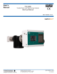
User’s
Manual
TDLS220
Tunable Diode Laser Spectroscopy Analyzer
Start-up Manual
IM11Y01B02-11E-A
Yokogawa Corporation of America
Yokogawa Corporation of America
2 Dart Road, Newnan, Georgia U.S.A. 30265
Tel: 1-800-258-2552 Fax: 1-770-254-0928
IM11Y01B02-11E-A
3rd Edition
i
PREFACE
This Instruction Manual has been compiled for Owners/Operators of the
Model TDLS220 Tunable Diode Laser Analyzer
SAFETY should be considered first and foremost importance when
working on the equipment described in this manual. All persons using
this manual in conjunction with the equipment must evaluate all
aspects of the task for potential risks, hazards and dangerous
situations that may exist or potentially exist. Please take appropriate
action to prevent ALL POTENTIAL ACCIDENTS.
AVOID SHOCK AND IMPACT TO THE ANALYZER THE LASERS CAN BE PERMANENTLY DAMAGED THE LASERS CAN BE PERMANENTLY DAMAGED This analyzer contains a Class 1 laser source (EN
60825-1 classification; eye-safe under all operating
conditions). However, it is recommended to avoid direct eye exposure to the laser radiation.
Notice
•
•
•
•
•
•
•
This manual should be passed on to the end user.
The contents of this manual are subject to change
without prior notice.
The contents of this manual shall not be reproduced or copied, in part or in whole, without permission.
This manual explains the functions contained in
this product, but does not warrant that they are
suitable the particular purpose of the user.
Every effort has been made to ensure accuracy in
the preparation of this manual. However, when you
realize mistaken expressions or omissions, please
contact the nearest Yokogawa Electric representative or sales office.
This manual does not cover the special specifications. This manual may be left unchanged on any change of specification, construction or parts when the change does not affect the functions or performance of the product.
If the product is not used in a manner specified in
this manual, the safety of this product may be impaired.
Yokogawa is not responsible for damage to the instrument,
poor performance of the instrument or losses resulting from
such, if the problems are caused by:
The Instrument is packed carefully with shock absorbing materials,
nevertheless, the instrument may be damaged or broken if subjected
to strong shock, such as if the instrument is dropped. Handle with
care.
• Improper operation by the user.
• Use of the instrument in improper applications
• Use of the instrument in an improper environment or improper utility program
• Repair or modification of the related instrument by an engineer not authorized by Yokogawa.
Safety and Modification Precautions
• Follow the safety precautions in this manual when using the product to ensure protection and safety of the human body, the product and the system containing the product.
Media No. IM 11Y01B02-11E-A
3rd Edition :August. 2012 (YCA)
All Rights Reserved Copyright © 2012, Yokogawa Corporation of America
IM 11Y01B02-11E-A
3rd Edition :August 14, 2012-00
ii
Safety Precautions
Safety, Protection, and Modification of the Product
• In order to protect the system controlled by the product and the product itself and ensure safe operation, observe the safety precautions
described in this user’s manual. We assume no liability for safety if users fail to observe these instructions when operating the product.
• If this instrument is used in a manner not specified in this user’s manual, the protection provided by this instrument may be impaired.
• If any protection or safety circuit is required for the system controlled by the product or for the product itself, prepare it separately.
• Be sure to use the spare parts approved by Yokogawa Electric Corporation (hereafter simply referred to as YOKOGAWA)
when replacing parts or consumables.
• Modification of the product is strictly prohibited.
• The following safety symbols are used on the product as well as in this manual.
DANGER
This symbol indicates that an operator must follow the instructions laid out in this manual in order to avoid the risks, for the human body, of injury,
electric shock, or fatalities. The manual describes what special care the operator must take to avoid such risks.
WARNING
This symbol indicates that the operator must refer to the instructions in this manual in order to prevent the instrument (hardware) or software from
being damaged, or a system failure from occurring.
CAUTION
This symbol gives information essential for understanding the operations and functions.
Note!
This symbol indicates information that complements the present topic.
This symbol indicates Protective Ground Terminal
This symbol indicates Function Ground Terminal (Do not use this terminal as the protective ground terminal.)
Warning and Disclaimer
The product is provided on an “as is” basis. YOKOGAWA shall have neither liability nor responsibility to any person or entity with respect to any direct or
indirect loss or damage arising from using the product or any defect of the product that YOKOGAWA cannot predict in advance.
IM 11Y01B02-11E-A
3rd Edition :August 14, 2012-00
iii
<1 QUICK START> 1-4
1-5
SAFETY should be considered first and foremost importance when working on the equipment described in this manual. All persons using this
manual in conjunction with the equipment must evaluate all aspects of the task for potential risks, hazards and dangerous situations that may
exist or potentially exist. Please take appropriate action to prevent ALL POTENTIAL ACCIDENTS.
1) Safe lifting and carrying
If it is necessary to relocate the analyzer, it should be lifted by at least two people wearing protective gloves and steel toe boots.
The analyzer should be always transported either in a vertical position as shown in the picture, or in a horizontal position with the mounting
plate facing down. If transported horizontally, it must be held by the mounting plate only. In vertical position, it is acceptable to hold the analyzer
by the elements in the “grip” area. Never hold the analyzer by applying force to the elements in the “Do not grip” zone or to the conecting cables
and tubes. If a winch or another hoisting device is used, it can be hooked to the upper mounting holes.
2) Electrical hazard
The areas of potentially hazardous voltage are labeled with this sign:
The analyzer is powered by either a ~220V, 50 Hz or ~120V, 60 Hz (model specific). During normal operation this voltage is not accessible from
outside of the enclosure. However, end user is responsible for connecting the mains to the analyzer terminals in the Power/Temperature
Controller box (right bottom block in the diagram above).
THE WIRES BEING CONNECTED MUST BE DISCONNECTED FROM ANY VOLTAGE SOURCES DURING THIS PROCEDURE.
Protective ground wire must be connected to the designated terminal labeled by the corresponding
symbol.
DO NOT OPEN THE POWER MODULE ENCLOSURE WHEN THE ANALYZER IS ENERGIZED.
Some maintenance and troubleshooting operations require opening the Electronics Controller box (left bottom block in the diagram above)
while the analyzer is powered. The highest voltage present in this box is 24V and is not hazardous. A higher voltage (+65V, 10 mA)
is shielded with an isolating plate and labeled. .
3) Thermal hazard
The gas cell can be heated up to +120 ºC and cause thermal injury to unprotected skin at direct contact. In normal configuration the cell is
wrapped in a thermal isolation jacket that prevents such incidents. DO NOT REMOVE THERMAL JACKET WHEN THE ANALYZER IS
POWERED. Prior to performing service operations that require removal of the thermal jacket, power the analyzer down and wait 30 minutes to
let the temperature drop to a safe level.
Areas of a potentially hazardous temperature are labeled with the following symbol:
IM 11Y01B02-11E-A
3rd Edition :August 14, 2012-00
iv
<1 QUICK START> 1-5
4) Chemical hazard
Analyzer can measure a wide variety of chemical species in various gas mixtures. CHEMICAL COMPOSITION OF SAMPLE SUPPLIED TO
THE ANALYZER AND ITS VARIATION LIMITS MUST BE APPROVED BY YOKOGAWA to ensure safe operation of the device. Gas stream
supplied to the analyzer gas cell for analysis can be potentially harmful for people and environment. DO NOT DISCONNECT THE ANALYZER
GAS TUBES (INLET OR OUTLET) DURING ITS OPERATION. CHECK FOR LEAKS AFTER INSTALLATION BEFORE SUPPLYING THE GAS
SAMPLE. FLUSH ANALYZER WITH NITROGEN OR INSTRUMENT AIR FOR 15 MINUTES BEFORE DISCONNECTING FROM THE GAS
LINES.
The inlets and outlets of the sampled gas are labeled with the warning sign:
5) Other labels used on this analyzer
The areas of potentially hazardous voltage are labeled with this sign:
Caution, refer to the user manual
Alternating current
Direct current
Protective ground terminal
Function ground terminal (do not use this terminal as the protective
ground terminal.)
Warranty and service
Yokogawa products and parts are guaranteed free from defects in workmanship and material under normal use and service for a period of
(typically) 12 months from the date of shipment from the manufacturer. Individual sales organizations can deviate from the typical warranty
period, and the conditions of sale relating to the original purchase order should be consulted. Damage caused by wear and tear, inadequate
maintenance, corrosion, or by the effects of chemical processes are excluded from this warranty coverage.
In the event of warranty claim, the defective goods should be sent (freight paid) to the service department of the relevant sales organization for
repair or replacement (at Yokogawa discretion). The following information must be included in the letter accompanying the returned goods:
• Part number, model code and serial
• Number
• Original purchase order and date
• Length of time in service and a description of the
process
• Description of the fault, and the circumstances of
failure
• Process/environmental conditions that may be
related to the failure of the device.
• A statement whether warranty or nonwarranty
service is requested
• Complete shipping and billing instructions for
return of material, plus the name and phone
number of a contact person who can be reached
for further information.
Returned goods that have been in contact with process fluids must be decontaminated/ disinfected before shipment. Goods should carry a
certificate to this effect, for the health and safety of our employees. Material safety data sheets should also be included for all components of
the processes to which the equipment has been exposed.
IM 11Y01B02-11E-A
3rd Edition :August 14, 2012-00
TOC-1
Model TDLS220
Tunable Diode Laser Spectroscopy Analyzer
Start-up Manual
IM 11Y01B02-11E-A 2nd Edition
ConteNtS
Preface .................................................................................................................................................................................... i
Safety Precautions................................................................................................................................................................. ii
1
Instrument Check........................................................................................................................................................1-1
2
Quick Start...................................................................................................................................................................2-1
3
Installation and Wiring................................................................................................................................................3-1
3.1 Mounting the Analyzer................................................................................................................ 3-1
3.2 Sample Inlet and Outlet considerations..................................................................................... 3-2
3.3 Wiring Details............................................................................................................................. 3-3
3.4 Purge Gas Requirements and Hazardous Area Systems........................................................... 3-5
Revision Record....................................................................................................................................................................... i
IM 11Y01B02-11E-A
3rd Edition :August 14, 2012-00
<1 INSTRUMENT CHECK> 1-1
1 INSTRUMENT CHECK
Upon delivery, unpack the instrument carefully and inspect it to ensure that it was not damaged during
shipment. If damage is found, retain the original packing materials (including the outer box) and then
immediately notify the carrier and the relevant Yokogawa sales office.
Make sure the model number on the nameplate of the instrument agrees with your order.
The nameplate will also contain the serial
number and any relevant certification marks.
Be sure to apply correct power to the unit, as
detailed on the nameplate.
For products used within the European
Community or other countries requiring the CE
mark and/or ATEX classification, the following
labels are attached (as appropriate):
IM 11Y01B02-11E-A
3rd Edition :August 14, 2012-00
<2 QUICK START> 2-1
2 QUICK START
Step
Title
Description
1.0
Preparation
Carefully un-pack and check equipment for any obvious damage.
1.1
Ensure the appropriate utilities are available and ready for connection. These may include electrical
power, nitrogen purge gas, instrument air, validation gas, etc. Make sure the sample handling and
conditioning system meets the sample inlet and outlet requirements for TDLS220
1.2
Ensure you comply with any local and/or site specific safety requirements.
1.3
Read the appropriate sections of the Instruction Manual BEFORE starting any installation work – Contact
Yokogawa Laser Analysis Division or Local Agent if any doubts!
2.0
Installation
Ensure there is sufficient physical space to mount the analyzer and allow suitable space for any future
maintenance access. Mount the analyzer/panel to a secure vertical surface using appropriate style
shake-proof fasteners. Avoid areas prone to vibration to ensure long term reliability – the analytical
measurement itself is not affected by vibration.
3.0
Wiring
Ensure that all wiring will meet local codes and site requirements
3.1
Connect protective ground wire to the protective ground terminal of TDLS220. Use minimum 14 AWG
wire or equivalent.
3.2
Connect the appropriate single phase AC electrical power supply.
• 110/240 50/60 Hz to the power/heater control line filter using supplied cable crimp terminal plugs
• A suitable mains disconnect device must be supplied. Refer to the “Installation” section of this manual for details.
3.3
Check termination details before proceeding to prevent damage to electronics.
Connect any analog I/O signals to the optional analog I/O Board. Outputs land on TB8 and any pressure
inputs land on TB9.
Heated flow cells have the gas temperature signal already terminated at TB9.
A table of wiring terminations is included in this Instruction Manual
3.4
Connect any other equipment such as Ethernet, solenoid valves, digital I/O, etc. Note. Solenoids require
directional diode or ferrite coil on field wires at terminal block to prevent noise spikes.
3.5
Check terminations and ensure all cable shields are landed per supplied wiring details.
4.0
Utilities and Sample
NOTE! – All purge, Validation Gas and other gas utility lines should be thoroughly cleaned, dried and purged prior to
connecting to the analyzer – Failure to do so can result in serious damage to the TDLS220 or contamination to the
internal optical elements resulting in poor performance
Connect the appropriate analyzer purge gas (nitrogen for oxygen analyzers) and make site connections
per the supplied purge gas sequence details (including any Hazardous area purge system). Start the
purge gas flow accordingly.
Some Oxygen analyzers may be capable of operating with Instrument Air purge alone or in conjunction
with Nitrogen purge of the measurement enclosure.
4.1
Connect process gas sample to the inlet port and the process sample return/vent to the flow cell outlet
port.
Ensure all inlet lines are clean and dry before connecting to prevent contamination of the flow cell and
flow cell window/mirror.
4.2
Leak-check all connections and ensure pressure ratings are not exceeded!
5.0
Power-Up
Make sure the power module door is closed. Do not open this door when the analyzer is powered. Apply
the AC power to the analyzer.
5.1
Open the Control module door. Inside this module use the internal On-Off switch to power-up the
analyzer (located lower right hand side).
5.2
Observe the various LED clusters on the backplane and FPGA boards.
All blue LEDs located lower right side on the back-plane should be on.
5.3
Observe the Green power indicator on the SBC.
5.4
Observe the LEDs on the optional analog I/O board.
IM 11Y01B02-11E-A
3rd Edition :August 14, 2012-00
<2 QUICK START> 2-2
6.0
Checking
If there is an installed optional 6.5” Display and Keypad – Observe the Main Menu messages and status
information.
6.1
If there is no installed User Interface, then connect a laptop PC via Ethernet to the SBC mounted on the
backplane. Initiate the supplied UltraVNC software from the laptop to initiate a VNC session with the
‘blind’ analyzer and observe the analyzer Main Menu via the laptop.
6.2
AT this time there may be one or more alarm message due to low transmission, out of range parameters or other –
final system configuration is still required!
6.3
If the analyzer displays a Warning “Validation Required” then this indicates that there is no target gas
absorption peak found at start-up. Either, shut down the analyzer, introduce some measured gas into the
flow cell and re-start or perform a validation. This will ensure that the analyzer is correctly tuned to the
measurement gas absorption peak. If this Warning cannot be cleared by either method, please contact
Yokogawa Laser Analysis Division or your local agent for further assistance.
7.0
Configure
BASIC
7.1
By way of the appropriate user interface, the correct process parameters and other parameters can now
be entered.
Enter the Basic Menu and go to Configure.
7.2
Gas Pressure
Enter in the correct process gas pressure (if Active, see Advanced Configure).
7.3
Gas Temperature
Enter in the correct process gas temperature (if Active, see Advanced Configure).
7.4
If any other parameters are required to be set (such as analog I/O ranges, alarms levels, Auto Validation
sequences) then the Advanced Menu needs to be accessed.
Advanced Menu access is Password protected (default 1234, can be changed by user if necessary) and should only be
used by skilled and trained persons - Contact Yokogawa Laser Analysis Division or Local Agent if any doubts!
Go to the Data section under Basic and configure the appropriate ‘Record Result Data’ settings. This will
ensure the analyzer stores important information during operation that may be used to verify operation/
status/diagnostics and other trouble shooting.
8.0
Configure
ADVANCED
Using the correct password (Default 1234), enter in to the Advanced Menu, then the Configure.
8.1
Select the desired measurement units for path length, pressure and temperature.
8.2
Select Fixed or Active.
If Fixed, enter in the correct process gas pressure.
If Active, enter in the 4-20mA input signal range proportional to the pressure transmitter output range.
8.3
Select Fixed or Active.
If Fixed, enter in the correct process gas temperature.
If Active, enter in the 4-20mA input signal range proportional to the temperature range.
8.4
Configure the system I/O by entering in to the System I/O sub menu in Configure.
8.5
If the optional Analog I/O board is installed, then select Analog Output and set the appropriate 4mA and
20mA values for Ch 1 Concentration and Ch 2 Transmission.
8.6
Select what mode (Block, Track or Hold) the 4-20mA outputs are to be when the analyzer is in Warning,
Fault, Export Data and Calibration Modes.
8.7
Configure Digital I/O – Warnings and Faults. Many of these will be factory pre-set so if unsure about any
settings then leave as Factory Default.
Select and set level for Alarm Limit to either the Measured Gas or Transmission.
8.8
Go to the Data screen and set the appropriate parameters for ‘Record Result Data’ and ‘Spectrum
Capture’. These will ensure the analyzer stores important information during operation that may be used
to verify operation/status/diagnostics and other trouble shooting.
IM 11Y01B02-11E-A
3rd Edition :August 14, 2012-00
<2 QUICK START> 2-3
8.9
Go to the Trends screen and review/plot several of the listed parameters to check analyzer performance
over a period of time.
8.10
Non-Process
Parameters
If the application is to using purge gas containing the target gas (e.g. Oxygen measurement with
Instrument Air Purge) then the Non-Process parameters should be configured as detailed later in this
manual under the Software Section.
9.0
Normal Operation
When the site/field configuration is complete and the analyzer has operated for at least two hours
without any functional alarms, then perform an export data routine.
9.1
To Export Data, simply insert an empty USB memory stick in to a USB port on the launch unit back
plane. The data transfer may take several minutes.
DO NOT REMOVE THE MEMORY STICK DURING THIS TIME!
9.2
Close out the VNC software and disconnect the service PC – if connected.
9.3
Ensure the doors/lids are closed and tightly sealed.
9.4
The system is now in normal operation mode.
9.5
We RECOMMEND sending all the Exported Data files to Yokogawa Laser Analysis Division along
with any notes and comments. We will then be able to store these files on a master record for
future reference.
Please carefully read the appropriate Sections of this Instruction Manual. The TDLS220 Tunable Diode
Laser (TDL) Analyzer is a technologically advanced instrument that requires the appropriate care when
handling, installing and operating.
Failure to do so may result in damage and can void any warranty!
If there is any doubt about any aspect of the Instrument installation or use, please contact Yokogawa
Laser Analysis Division and/or your authorized Representative/Distributor.
IM 11Y01B02-11E-A
3rd Edition :August 14, 2012-00
<3 INSTALLATION AND WIRING> 3-1
3 Installation and Wiring
3.1 Mounting of the Analyzer
Refer to the SAFETY section (Safe handling and relocation) for instructions on holding and moving the
analyzer.
The TDLS220 is suitable for wall mounting by means of the four corner located mounting holes as shown
below: The holed are ½” sized for typically 3/8” or ¼” bolts and should be used with appropriate sized
flat and locking washers. Ensure the analyzer is securing fastened and that there is suitable access for
maintenance, etc.
The analyzer is designed for operation outside buildings, at normal environmental conditions (see
Environmental specifications, page 11). However, it must be protected from direct rain and snow fall.
Mounting in a vibration free environment will ensure prolonged service life. Mounting in vibration prone
areas may introduce operational issues. Please consider mounting location with care.
The actual measurement is NOT affected by vibration, it is an instrument life-time reliability
consideration.
22”
22”
22”
Figure 1 - Mounting Dimensions
IM 11Y01B02-11E-A
3rd Edition :August 14, 2012-00
<3 INSTALLATION AND WIRING> 3-2
3.2 Sample Inlet and Outlet Considerations
The following criteria should be considered when selecting the installation point in respect to the process
conditions (1/4” OD Swagelok tube fittings):
Process Gas Condition: - The sample should be clean, dry, non-condensing at the inlet to the
sample cell. The dew point of the sample should be below the sample cell operating temperature.
If the sample cell is not heated and un-insulated then the sample must be non-condensing through the entire ambient operating conditions.
NOTE: Oils, waxes, impure cleaners, and other deposits on the sample cell/mirror will cause
optical noise and subsequent analytical performance degradation. Please take all necessary precautions to ensure the incoming sample gas is clean and dry at all times!
Process Gas Flow Conditions – Typically 1-10 lts/min sample flow. A so-called normal flow-rate
would be in the order of 2-3 lts/min. Higher flow-rates will improve the sample lag time within the
measurement cell. Sample flowmeter can be typically installed on the inlet when equipped with
needle valve. Excessive flow-rates may result in gas temperature control issues if the delta T of
incoming gas and cell temperature set-point exceed 15OC.
Process Gas Temperature – It is recommended that the sample gas inlet remains within +/-15OC
of the sample cell temperature set-point. If the sample cell is un-heated then the sample gas
should be with +/-10OC of the ambient temperature. Please ensure that the process gas
entering the sample cell is above the dew point. If necessary, utilize membrane or coalescing type
filter device on the inlet.
Lower gas temperatures generally lead to better measurements.
• Process Gas Pressure – It is recommended that the analyzer be installed at a location where
pressure fluctuations are minimized. Generally as a guide, if the temperature of the gas at the point
where the analyzer is to be installed is to vary by more than +/-0.05 Bar (+/-0.725 psi) then an
“Active” input signal should be used for compensation.
Ensure the analyzer has been selected and configured to suit the maximum operating gas
pressure.
Ensure the process isolation windows have been selected and configured to suite the maximum
design gas pressure.
Lower gas pressures generally lead to better measurements.
Process Dust/Particulate Matter – It is recommended that the process gas is filtered to <2u using process
analytical grade filtration systems.
IM 11Y01B02-11E-A
3rd Edition :August 14, 2012-00
<3 INSTALLATION AND WIRING> 3-3
3.3
Wiring Details
Screw Terminal Block (SAK2.5) Details: (also see following diagram for internal wiring).
TB
1
2
Field or
Factory
Factory
Field
Terminal
No.
Function
1
+24 VDC
2
0 VDC
3
+24 VDC
4
0 VDC
1
SV 1 remote
Cal/Val initiate signal loop (SV # 1) to Remote voltage free contacts/switch. Do not apply external power!
SV 2 remote
Cal/Val initiate signal loop (SV # 2) to Remote voltage free contacts/switch. Do not apply external power!
SV 3 remote
Cal/Val initiate signal loop (SV # 2) to Remote voltage free contacts/switch. Do not apply external power!
1
SV 1 +
2
SV 1 -
24VDC power output signal to actuate external solenoid valve # 1.
Max 12 Watts requires ferrite coil on wires.
3
SV 2 +
4
SV 2 -
5
SV 3 +
6
SV 3 -
1
Warning
Alarm
2
3
4
5
6
3
4
Field
Field
2
3
4
5
Field
1
DC power from the 24 power supply in adjacent enclosure.
24VDC power take-off to integral purge indicator/switch unit
(when fitted)
24VDC power output signal to actuate external solenoid valve # 2.
Max 12 Watts requires ferrite coil on wires.
24VDC power output signal to actuate external solenoid valve # 3.
Max 12 Watts requires ferrite coil on wires.
NC - Closed contact on Warning/Power-off state
C - Common contact – rated max 1A @ 24 VDC
NO - Open contact on Warning/Power-off state
Fault
Alarm
6
5
Notes/Comments
NC - Closed contact on Warning/Power-off state
C - Common contact – rated max 1A @ 24 VDC
NO - Open contact on Warning/Power-off state
User Alarm
NC - Closed contact on Warning/Power-off state
2
C - Common contact – rated max 1A @ 24 VDC
3
NO - Open contact on Warning/Power-off state
4
5
Purge Alarm
C - Common contact – rated max 265 V AC/DC, 150 mA
NO - Open contact on loss of purge pressure
IM 11Y01B02-11E-A
3rd Edition :August 14, 2012-00
<3 INSTALLATION AND WIRING> 3-4
6
Factory
7
Factory
8
Field
9
Factory
and/or
Field
1
- Transmit
3
+ Receive
4
- Receive
1-8
Detect
Analog
#1 output
+
Analog
#2 output
+
Analog
#3 output
+
1
Gas
Temperature
Compensation
Externally powered 4-20 mA gas temperature signals are wired to
1 (+) and 2(-), 3 not used.
Loop powered temperature transmitter can be connected to 1 (-)
and 3 (+24 VDC), 2 not used
Gas
Pressure
Compensation
Externally powered 4-20 mA gas pressure signals are wired to 1
(+) and 2(-), 3 not used.
Loop powered pressure transmitter can be connected to 1 (-) and
3 (+24 VDC), 2 not used
2
3
5
6
Factory
+ Transmit
2
4
14
Ethernet
1-4
-
-
-
Mini-Display
Internal connections only – do not use
Cal/Val initiate signal loop (SV # 1) to Remote voltage free contacts/switch. Do not apply external power!
Cal/Val initiate signal loop (SV # 2) to Remote voltage free contacts/switch. Do not apply external power!
Cal/Val initiate signal loop (SV # 2) to Remote voltage free contacts/switch. Do not apply external power!
Internal connections only – do not use
Figure 2 – Internal Wiring Diagram, including optional cell heating and optional purge unit
IM 11Y01B02-11E-A
3rd Edition :August 14, 2012-00
<3 INSTALLATION AND WIRING> 3-5
3.4 Purge Gas Requirements and Hazardous Area Systems
The TDLS220 Analyzer requires a continuous nitrogen (optionally instrument air) gas purge to prevent ambient
oxygen ingress to the optical path, when oxygen is the measured gas. The flow rate can be minimized as long
as it prevents any ambient oxygen ingress to the measurement optical path. Other purge gases may be used as
long as they do not contain any of the measured gas and a clean, dry, etc.
For hazardous area operation, the same nitrogen purge gas is used to purge the entire analyzer (including nonoptical path sections such as the electronics). Refer to purge diagrams below.
In some applications, Instrument Air (I/A) may be used as the purge gas. Special software configurations must
be set-up under the “Configure” section called “Non-Process Parameters” – refer to software section of this
manual for further details.
The flow rate can be minimized as long as it prevents any ambient oxygen ingress to the measurement optical
path. Other purge gases may be used as long as they do not contain any of
N2
2 Purge Inlet
FLOW CELL
ELECTRONICS
CONTROLLER
LASER &
DETECT
POWER
HEAT
TRACE
N2
2 Purge Vent
Figure 3 – Safe Area/General Purpose N2
2 Analyzer Purge Schematic
IM 11Y01B02-11E-A
3rd Edition :August 14, 2012-00
<3 INSTALLATION AND WIRING> 3-6
I/A Purge Inlet
LASER &
DETECT
FLOW CELL
ELECTRONICS
CONTROLLER
POWER
HEAT
TRACE
I/A Purge Vent
Figure 4 – Safe Area/General Purpose I/A Analyzer Purge Schematic
I/A Purge Inlet
FLOW CELL
N2
2 Purge Inlet
LASER &
DETECT
General
Purpose
or
Safe Area
N2
2 Purge Vent
ELECTRONICS
CONTROLLER
POWER
HEAT
TRACE
I/A Purge Vent
Figure 5 – Safe Area/General Purpose Dual/Split N2
2 & I/A Analyzer Purge Schematic
IM 11Y01B02-11E-A
3rd Edition :August 14, 2012-00
<3 INSTALLATION AND WIRING> 3-7
N2
2 Purge Inlet
LASER &
FLOW CELL
ELECTRONICS
CONTROLLER
DETECT
POWER
HEAT
TRACE
Hazardous
Area
Div 2 BCD
ATEX CAT3
N2
2 Purge Vent
Figure 6 – Hazardous Area N2
2 Analyzer Purge Schematic
Figure 7 – Hazardous Area I/A Analyzer Purge Schematic
Please also refer to any separate Purge System Original Manufacturers Operating Instructions and
Manuals in conjunction with this Instruction Manual.
IM 11Y01B02-11E-A
3rd Edition :August 14, 2012-00
<REVISION RECORD> i1-18
Manual Title:
Model TDLS220 Tunable Diode Laser Spectroscopy Analyzer Start-up Manual
Manual Number: IM 11Y01B02-11E-A
Edition
1st
Date
April 2008
Remark (s)
Newly Published
2nd
June 2012
Revisions:
3rd
August 2012
1. Formatting was corrected.
2. Preface section was added.
3. Instrument check, now section one was added.
4. Quick Start section changed to section 2.
5. Installation and wiring section 3 was added.
6. Revision Record was added.
7. Back panel for CD holder was added.
Revisions:
1. Updated Safety Precautions section.
2. Updated Quick Start section 2.
IM 11Y01B02-11E-A
3rd Edition :August 14, 2012-00
ocess/environmental conditions that may be related to the failure of the device.
tatement whether warranty or nonwarranty service is requested
mplete shipping and billing instructions for return of material, plus the name and phone number of
ntact person who can be reached for further information.
ods that have been in contact with process fluids must be decontaminated/ disinfected before shi
ld carry a certificate to this effect, for the health and safety of our employees. Material safety data
be included for all components of the processes to which the equipment has been exposed.
TDLS220 TruePeak Series Electronic User’s Manaul IM 11Y01B02-21E-A
CD-R
[Contents]
This CD-ROM contains information in PDF format that is necessary for sale and effective operation of the product.
he lines should be a red color and thickness here, see example photo of FLXA21 IM below> www.yokogawa.com/us
WARNING: This CD-ROM contains software, and is for use in a computer only. Do not play this on an audio CD player, as the high volume may damage your hearing or audio speakers.
copyright © 2012, Yokogawa Corporatoin of America. All Rights Reserved.
Yokogawa Corporation of America
North America
2 Dart Road, Newnan, GA 30265-1094, USA
Phone: 800-258-2552 Fax: 770-254-0928
12530 West Airport Blvd., Sugar Land, TX 77478
Phone: 281-340-3800 Fax: 281-340-3838
Yokogawa has an extensive sales and
distribution network.
Please refer to the website (www.
yokogawa.com/us) to contact your nearest
representative.
Mexico
Melchor Ocampo 193, Torre C, Oficina 3”B”
Veronica Anzures D.F., C.P. 11300
Phone: (55) 5260-0019, (55) 5260-0042
Yokogawa Canada, Inc.
Bay 4, 11133 40th Street SE, Calgary, AB Canada T2C2Z4
Phone: 403-258-2681 Fax: 403-258-0182
Subject to change without notice
Copyright ® 2012
03-1208 (A) I
Printed in The USA
IM 11Y01B02-11E-A
IM 11Y01B02-11E-A
3rd Edition :August 14, 2012-00