1
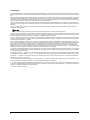
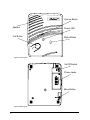
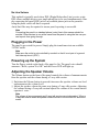
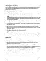
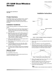
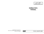
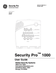
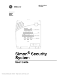
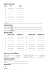
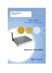
(PHUJHQF\5HVSRQVH6\VWHP 8VHU,QVWUXFWLRQV Table of Contents System Components 5 Control Panel 5 Wrist Panic 5 Pendant Panic 5 Setting up the System 7 Locating the Panel 7 Plugging in the Phone Line 7 Plugging in the Power 8 Powering up the System 8 Adjusting the Speaker Volume 8 Operation 9 Panic Operation 9 Remote Phone Control 10 Pager Communication 10 Testing the System 11 FCC Notices FCC Part 15 Information to the User Changes or modifications not expressly approved by GE Interlogix Inc. can void the user’s authority to operate the equipment. FCC Part 15 Class B This equipment has been tested and found to comply with the limits for a Class B digital device, pursuant to part 15 of the FCC Rules. These limits are designed to provide reasonable protection against interference in a residential installation. This equipment generates, uses, and can radiate radio frequency energy and, if not installed and used in accordance with the instructions, may cause harmful interference to radio communications. However, there is no guarantee that interference will not occur in a particular installation. If this equipment does cause harmful interference to radio or television reception, which can be determined by turning the equipment off and on, the user is encouraged to try to correct the interference by one or more of the following measures: ❑ Reorient or relocate the receiving antenna. ❑ Increase the separation between the equipment and receiver. ❑ Connect the affected equipment and the panel receiver to separate outlets, on different branch circuits. ❑ Consult the dealer or an experienced radio/TV technician for help. ACTA Part 68 This equipment complies with Part 68 of the FCC Rules. Located on this equipment is a label that contains, among other information, the FCC registration number and the ringer equivalence number (REN) for this equipment. If requested, this information must be provided to the telephone company. A plug and jack used to connect this equipment to the premises wiring and telephone network must comply with the applicable FCC Part 68 rules and requirements as adopted by ACTA. A compliant telephone cord and modular plug is provided with this product. It is designed to be connected to a compliant modular jack that is also compliant. See the Installation Instructions for details. The REN is used to determine the maximum number of devices that may be connected to your telephone line. Excessive RENs on a telephone line may result in devices not ringing in response to an incoming call. In most areas, the sum of all device RENs should not exceed five (5.0). To be certain of the number of devices that may be connected to a line, as determined by the total RENs, contact the local telephone company. For products approved after July 23, 2001, the REN for this product is part of the product identifier that has the format US:AAAEQ##TXXXX. The digits represented by ## are the REN without a decimal point (e.g., 03 is a REN of 0.3). For earlier products, the REN is separately shown on the label. If this equipment causes harm to the telephone network, the telephone company may temporarily disconnect your service. If possible, you will be notified in advance. When advance notice is not practical, you will be notified as soon as possible. You will also be advised of your right to file a complaint with the FCC. Your telephone company may make changes in its facilities, equipment, operations, or procedures that could affect the operation of your equipment. You will be given advanced notice in order to maintain uninterrupted service. If you experience trouble with this equipment, please contact the company that installed the equipment for service and repair information. The telephone company may ask you to disconnect this equipment from the network until the problem has been corrected or you are sure that the equipment is not malfunctioning. This equipment may not be used on coin service provided by the telephone company. Connection to party lines is subject to state tariffs. Contact the state public utility commission, public service commission or corporation commission for information. Alarm dialing equipment must be able to seize the telephone line and place a call in an emergency situation. It must be able to do this even if other equipment (telephone, answering system, computer modem, etc.) already has the telephone line in use. To do so, alarm dialing equipment must be connected to a properly installed RJ31X jack that is electrically in series with and ahead of all other equipment attached to the same telephone line. Proper installation is depicted in the figure below. If you have any questions concerning these instructions, you should consult your telephone company or qualified installer about installing the RJ31X jack and alarm dialing equipment for you. Network Service Provider's Facilities Customer Premises Equipment and Wiring Computer RJ31X Jack Alarm Dialing Equipment Unused RJ-11 Jack Telephone Line Telephone Network Demarcation Point Telephone Unused RJ-11 Jack Fax Machine Answering System Telephone Certification No. B4Z-USA-46042-AL-T REN: .1B 3 Canada Notice The Canadian Department of Communications label identifies certified equipment. This certification means that the equipment meets certain telecommunications network protective, operational, and safety requirements. The department does not guarantee the equipment will operate to the user’s satisfaction. Before installing this equipment, users should ensure that it is permissible to be connected to the facilities of the local telecommunications company. The equipment must also be installed using an acceptable method of connection. In some cases, the company’s inside wiring associated with a single-line individual service may be extended by means of a certified connector assembly (telephone extension cord). The customer should be aware that compliance with the above conditions may not prevent degradation of service in some situations. Repairs to certified equipment should be made by an authorized Canadian maintenance facility designated by the supplier. Any repairs or alterations made by the user to this equipment, or equipment malfunctions, may give the telecommunications company cause to request the user to disconnect the equipment. For your protection, make sure that the electrical ground connections of the power utility, telephone lines, and internal metallic water pipe system, if present, are connected together. &$87,21 Do not attempt to make connections yourself. Contact the appropriate electrician or electric inspections authority. The Load Number (LN) assigned to each terminal device denotes the percentage of the total load to be connected to a telephone loop which is used by the device, to prevent overloading. The termination on a loop may consist of any combination of devices subject only to the requirement that the total of the LNs of all the devices does not exceed 100. Load Number: .1 Certification Number: 867 11636A “AVI S: - L ´étiquette du ministère des Communications du Canada identifie le matériel homologué. Cette étiquette certifie que le matériel est conforme a certaines normes de protection, d ´ exploitation et de sécurité des réseaux de télécommunications. Le ministère n ´ assure toutefois pas que le matériel fonc-tionnera a la satisfaction de l ´ utilisateur. Avant d ´ installer ce matériel, l ´ utilisateur doit s ´ assurer qu´ il est permis de le raccorder aux installations de l ´ enterprise locale de télécommunication. Le matériel doit également etre installé en suivant une méthod acceptée de raccordement. Dans certains cas, les fils intérieurs de l´ enterprise utilisés pour un service individuel a ligne unique peuvent etre prolongés au moyen d´ un dispositif homologué de raccordement (cordon prolongateur téléphonique interne). L ´ abonné ne doit pas oublier qu ´ il est possible que la conformité aux conditions énoncées ci-dessus n ´ empechent pas le dégradation du service dans certaines situations. Actuellement, les enterprises de télécommunication ne permettent pas que l ´ on raccorde leur matériel a des jacks d ´ abonné, sauf dans les cas précis prévus pas les tarrifs particuliers de ces enterprises. Les réparations de matériel homologué doivent etre effectuées pas un centre d ´ entretien canadien autorisé désigné par le fournisseur. La compagne de télé-communications peut demander a l ´ utilisateur de débrancher un appareil a la suite de réparations ou de modifications effectuées par l ´ utilisateur ou a cause de mauvais fonctionnement. Pour sa propre protection, l ´ utilisateur doit s ´ assurer que tous les fils de mise a la terre de la source d ´ énergie électrique, des lignes téléphoniques et des canalisations d ´´ eau métalliques, s ´ il y en a, sont raccordés ensemble. Cette précaution est particulièrement importante dans les régions rurales. Avertissment. - L ´ utilisateur ne doit pas tenter de faire ces raccordements lui-meme; il doit avoir recours a un service d ´ inspection des installations élec-triques, ou a electricien, selon le cas”. Une note explicative sur les indices de charge (voir 1.6) et leur emploi, a l ´ intention des utilisateurs du matériel terminal, doit etre incluse dans l ´ information qui accompagne le materiel homologué. La note pourrait etre rédigée selon le modèle suivant: “L ´ indice de charge (IC) assigné a chaque dispositif terminal indique, pour éviter toute surcharge, le pourcentage de la charge totale qui peut etre raccordée a un circuit téléphonique bouclé utilisé par ce dispositif. La terminaison du circuit bouclé peut etre constituée de n ´ import somme des indices de charge de l ´ ensemble des dispositifs ne dépasse pas 100.” L ´ Indice de charge de cet produit est ____________. 4 System Components The LifeGard system is composed of the control panel and a wrist and pendant panic. Control Panel The control panel is the processing unit for all functions. It receives signals from panic sensors and reports emergencies through the phone line. When the panel cover is closed, the panel buttons operate the emergency notification system. The user operates the panel by pressing panel buttons. When the panel cover is open, the buttons are used to program the emergency notification system. The panel can be programmed on-site by the installer or user. Wrist Panic The Wrist Panic Sensor is a wireless device designed to be used throughout your premises. The sensor is worn on the wrist with a wrist strap (included). Pendant Panic The Pendant Panic Sensor is a wireless device designed to be used throughout the installation site. The sensor can be worn around the neck with a removable cord (included) or on the user’s belt with an optional leather belt holster. Sensor Care Do not immerse sensors in water. Wipe clean using a soft cloth with a mild detergent. 5 Volume Button Speaker Power LED me Volu Call Button Status Button Power Status Figure 1. Front of panel On/Off Switch Phone Jacks Menu Button Figure 2. Back of panel 6 Setting up the System This section describes how to set up the basic system. Installing the system consists of the following procedures: ❑ ❑ ❑ ❑ ❑ Find a location for the panel Plug in the phone line Plug in the power Power up the system Adjust the speaker volume Locating the Panel The system control panel must be located with access to an incoming phone line and 110 VAC power. Locate the panel on a table or countertop where it is convenient to use (for example, on a nightstand near a bed). Locate the panel in a temperature and humidity controlled environment. Plugging in the Phone Line There are two methods for connecting the panel to a phone line; full line seizure and no line seizure. Full Line Seizure This method requires that the panel be wired ahead (or in front) of all other phones, answering machines, computers or any other devices on the phone line. This allows the panel to take over (seize) the phone line, even if another device on the line is in use. 1. Plug in the phone cord to a premises phone jack. 2. Plug the other end to the LINE jack on the back of the panel. 3. Plug additional devices such as phones and answering machines to the PHONE jack on the back of the panel. 7 No Line Seizure This method is typically used where DSL (Digital Subscriber Line) service exists. DSL allows multiple devices on a single phone line to be used simultaneously. Simply connecting the panel LINE jack to an available phone jack on the premises using the phone cord is all that is required. An in-line filter may be required to ensure panel reporting is successful. Note Connecting the panel to a standard phone (voice) line in this manner should be avoided. Other devices in use at the same time the panel is using the line can prevent reports from going through. Plugging in the Power The panel is pre-wired for power. Simply plug the transformer into an available 110VAC outlet. Note Make sure the outlet is not controlled by a switch or that it is not part of a ground fault interrupt circuit (GFIC). Powering up the System Turn the Power switch on the back of the panel to On. The panel voice should announce “Hello, system X is OK” and the Power LED will light up. Adjusting the Speaker Volume The Volume button on the front of the panel controls the volume of announcements from the speaker and the volume during a 2-way talk session. ❑ ❑ Each time the Volume button is pressed it increases the speaker volume one level and announces the volume level. Adjust the speaker volume the same way during a 2-way talk session. Adjusting the volume during a 2-way talk session adjusts the volume of the central station operator’s voice. Note The volume of announcements and 2-way talk sessions are independent. When a 2-way talk session ends the speaker volume returns to the level set for announcements. 8 Operation Panic Operation Activating a portable panic sensor or the panel’s Call button places an emergency call to the central station. To activate a portable panic sensor: ❑ Wrist Panic - Press the button until its red LED blinks. ❑ Pendant Panic - Press and hold the button for 2 seconds. To activate the panel’s Call button: The panel’s Call button can be set up by your installer to operate in one of two ways - a single press or two presses. The Call button may be disabled. Single Press: 1. Press the Call button. 2. The system announces “Contacting monitoring station, please remain calm.” Note There may be a slight delay between the time the button is pressed and when the panel announces it is contacting the station. Two Presses: 1. Press the Call button once. The panel announces “Press call again for Emergency call, or press Status to cancel.” 2. Press the Call button again to initiate an emergency call or press Status to cancel the call. You may also initiate an emergency call by holding down the Call button until the system announces “Contacting monitoring station, please remain calm.” After initiating a call the panel will... ❑ start blinking the Status LED. ❑ dial the central station ❑ announce “Contacting monitoring station, please remain calm.” This message will be repeated every 60 seconds until contact is made with the central station. ❑ report an alarm to the central station. ❑ begin a 2-way audio session between you and the central station operator if your system is set up for 2-way audio. 9 Remote Phone Control The 2-way audio functions of the LifeGard system can be accessed from an off-site phone. You can listen in to the room, talk or have a 2-way conversation with someone near the LifeGard system. Connecting to the LifeGard system The method of connecting to the LifeGard system through an off-site phone is dependent on how a programming option (Option 20: Ring/Hang/Ring) is programmed by your installer. The following instructions assume your system is set to the factory default of 1. This setting is used when an answering machine exists on the same phone line as the LifeGard system. Ask your installer for instructions if the option is not set to 1. To connect to the LifeGard system: 1. Call the panel location. 2. Let the phone ring once, then hang up. 3. Wait at least 10 seconds but no more than 40, then call the panel location again. The panel should answer on the first ring. 4. Enter ‚ + Master Access Code + one of the following numbers: ❑ ❑ ❑ ❑ 0 or 1 to talk through the panel 2 to have a 2-way conversation through the panel 3 or 6 to listen through the panel 99 to end the connection Note The default Master Access Code is 1234. Contact your installer about changing this access code. Pager Communication Your system can be set up by your installer to report to a numeric display pager. Use the following table to determine which report the pager is displaying. Table 1: Pager Reporting Message Report Phone Test AC Power Restoral AC Power Failure Call Button Panic Wrist/Pendant Panic 10 Pager Display -101-101 -102-102 -103-103 -107-107 -108-108 Testing the System We recommend testing your LifeGard system after programming and on a weekly basis thereafter. It is important to test the panic sensors and phone numbers to ensure correct operation. Testing the portable panic sensors 1. Press the Menu button on the back of the panel until the panel announces “Sensor test, Press Status to select.” Note Pressing the Menu button cycles through 4 functions; Phone Test, Sensor Test, Add Sensor and Delete all Sensors. The panel will announce the current function each time the button is pressed. 2. Press the Status button on the front of the panel to start a sensor test. The panel announces “Sensor test is on, test sensor 1 panic.” 3. Press and hold a panic button for 3 seconds. It is not necessary to test sensors in any particular order. 4. The system will continue to prompt for panics that have not yet been tested. When all the sensors have been tested the panel will announce, “Sensor test complete, press Status.” 5. Press Status. The panel says “Sensor test OK.” Note The panel will prompt for each sensor in the order they were programmed. If there are no sensors programmed the panel says “Invalid. Zero sensors programmed.” It is not necessary to test the sensors in the order they are announced by the panel. Phone Test To test the programmed phone numbers: 1. Call the central station and tell the operator you will be testing your system. 2. Press the Menu button on the back of the panel once. The panel announces “Phone test. Press status to select.” 3. Press the Status button on the front of the panel. The panel says “Phone test is on” once a minute while the phone test is being completed. During a phone test the panel attempts to dial each of the programmed phone numbers. 4. If all phone numbers are dialed successfully the panel says “Phone test ok.” If all phone numbers are not successfully dialed the panel says “System communication failure.” 5. If your system fails the phone test, contact your system installer. 11 2266 SECOND STREET NORTH | NORTH SAINT PAUL MN | 800-777-2624 | www.interlogixinc.com ©2002 GE Interlogix,™ Inc. GE Interlogix and LifeGard are trademarks of GE Interlogix, Inc. 12 Document Number: 466-1936 Rev. A