1
MODEL 23 AND 23-1
ELECTRONIC PERSONAL DOSIMETER
SOFTWARE MANUAL
November 2014
Version 0.26
MODEL 23 AND 23-1
ELECTRONIC PERSONAL DOSIMETER
SOFTWARE MANUAL
November 2014
Version 0.26
LUDLUM MEASUREMENTS, INC.
501 OAK STREET, P.O. BOX 810
SWEETWATER, TEXAS 79556
325-235-5494, FAX: 325-235-4672
Table of Contents
1.0 INTRODUCTION ................................................................................................................................................. 1 1.1 OVERVIEW............................................................................................................................................................. 1 1.2 PRODUCT PACKAGE .............................................................................................................................................. 1 2.0 SOFTWARE LICENSE AGREEMENT ............................................................................................................. 2 3.0 OPERATION ENVIRONMENT ......................................................................................................................... 5 3.1 GENERAL ............................................................................................................................................................... 5 3.2 REQUIRED ENVIRONMENT ..................................................................................................................................... 5 3.3 DEVICE STRUCTURE .............................................................................................................................................. 6 4.0 DESCRIPTIONS AND SETTING-UPS .............................................................................................................. 7 4.1 SYSTEM CONFIGURATION ...................................................................................................................................... 7 4.2 PRODUCT CONFIGURATION ................................................................................................................................... 8 4.3 PROGRAM MENU WINDOWS (THE DOSIMETER SETTING DEVICE PROGRAM) ........................................................ 8 4.4 SETTING UP ......................................................................................................................................................... 10 5.0 OPERATIONAL INSTRUCTIONS .................................................................................................................. 11 5.1 STARTING THE PROGRAM .................................................................................................................................... 11 5.2 SCREEN INTERFACE ............................................................................................................................................. 11 5.3 MENU .................................................................................................................................................................. 13 5.4 DOSIMETER SETTINGS ......................................................................................................................................... 15 5.5 INDICATION DISPLAY .......................................................................................................................................... 18 5.6 DATA TRENDING MODE ...................................................................................................................................... 20 5.6.1 Table Display ............................................................................................................................................... 23 5.6.2 Graph Display .............................................................................................................................................. 24 5.7 MANUAL CALIBRATION....................................................................................................................................... 25 5.8 MAINTENANCE MODE ......................................................................................................................................... 27 5.9 SYSTEM SETTING................................................................................................................................................. 28 5.10 CLIENT CONTROL NUMBER ............................................................................................................................... 31 5.11 DOSIMETER DATA RESET .................................................................................................................................. 32 5.12 DOSIMETER SETTINGS (DOSE RATE) .................................................................................................................. 33 5.13 COUNTS READOUT ............................................................................................................................................ 36 5.14 ENTRY/EXIT RETENTION DATA ......................................................................................................................... 37 5.15 INFORMATION DATA ......................................................................................................................................... 39 6.0 TROUBLESHOOTING ...................................................................................................................................... 46 6.1 ERRORS AND SOLUTIONS ..................................................................................................................................... 46 7.0 ABNORMALITIES ............................................................................................................................................. 48 8.0 MAINTENANCE................................................................................................................................................. 49 Model 23 & 23-1
1
Section
Software Manual
1.0 Introduction
1.1 Overview
The Dosimeter Setting Device is designed for acquiring data from/changing
settings of the Model 23 Electronic Personal Dosimeter via its infrared data
communication interface. This device provides features such as reading out
configurations/cumulative dose from the dosimeter, and writing PC-entered
values into backward. The reading trend that is read out from the dosimeter can
be exported in a text format. The Dosimeter Setting Device Program supplied
with the Dosimeter Setting Device (hereinafter, the Program) is based on the
Microsoft® Windows® operating system.
1.2 Product Package
Ludlum Measurements, Inc.
Dosimeter Settling Device
1
Software CD-ROM
1
User’s Manual
1
Page 1
November 2014
Model 23 & 23-1
2
Section
Software Manual
2.0 Software License
Agreement
BY INSTALLING THIS SOFTWARE, YOU ARE CONSENTING TO BE
BOUND BY THIS AGREEMENT. IF YOU DO NOT AGREE TO ALL OF THE
TERMS OF THIS AGREEMENT, DO NOT INSTALL THE PRODUCT.
Single User License Grant: Ludlum Measurements, Inc. ("Ludlum") and its
suppliers grant to Customer ("Customer") a nonexclusive and nontransferable
license to use the Ludlum software ("Software") in object code form solely on a
single central processing unit owned or leased by Customer or otherwise
embedded in equipment provided by Ludlum.
Customer may make one (1) archival copy of the Software provided Customer
affixes to such copy all copyright, confidentiality, and proprietary notices that
appear on the original.
EXCEPT AS EXPRESSLY AUTHORIZED ABOVE, CUSTOMER SHALL NOT:
COPY, IN WHOLE OR IN PART, SOFTWARE OR DOCUMENTATION;
MODIFY THE SOFTWARE; REVERSE COMPILE OR REVERSE ASSEMBLE
ALL OR ANY
PORTION OF THE SOFTWARE; OR RENT, LEASE,
DISTRIBUTE, SELL, OR
CREATE DERIVATIVE WORKS OF THE
SOFTWARE.
Customer agrees that aspects of the licensed materials, including the specific
design and
structure of individual programs, constitute trade secrets and/or copyrighted
material of Ludlum. Customer agrees not to disclose, provide, or otherwise
make available such trade secrets or copyrighted material in any form to any
third party without the prior written consent of Ludlum. Customer agrees to
implement reasonable security measures to protect such trade secrets and
copyrighted material. Title to Software and documentation shall remain solely
with Ludlum.
LIMITED WARRANTY. Ludlum warrants that for a period of ninety (90) days
from the date of shipment from Ludlum: (i) the media on which the Software is
furnished will be free of defects in materials and workmanship under normal
use; and (ii) the Software substantially conforms to its published specifications.
Except for the foregoing, the Software is provided AS IS. This limited warranty
extends only to Customer as the original licensee. Customer's exclusive remedy
and the entire liability of Ludlum and its suppliers under this limited warranty will
be, at Ludlum or its service center's option, repair, replacement, or refund of the
Software if reported (or, upon request, returned) to the party supplying the
Software to Customer. In no event does Ludlum warrant that the Software is
Ludlum Measurements, Inc.
Page 2
November 2014
Model 23 & 23-1
Software Manual
error free or that Customer will be able to operate the Software without
problems or interruptions.
This warranty does not apply if the software (a) has been altered, except by
Ludlum, (b) has not been installed, operated, repaired, or maintained in
accordance with instructions supplied by Ludlum, (c) has been subjected to
abnormal physical or electrical stress, misuse, negligence, or accident, or (d) is
used in ultra hazardous activities.
DISCLAIMER. EXCEPT AS SPECIFIED IN THIS WARRANTY, ALL EXPRESS
OR IMPLIED CONDITIONS, REPRESENTATIONS, AND WARRANTIES
INCLUDING, WITHOUT LIMITATION, ANY IMPLIED WARRANTY OF
MERCHANTABILITY, FITNESS FOR A PARTICULAR PURPOSE,
NONINFRINGEMENT OR ARISING FROM A COURSE OF DEALING,
USAGE, OR TRADE PRACTICE, ARE HEREBY EXCLUDED TO THE
EXTENT ALLOWED BY APPLICABLE LAW. IN NO EVENT WILL LUDLUM
OR ITS SUPPLIERS BE LIABLE FOR ANY LOST REVENUE, PROFIT, OR
DATA, OR FOR SPECIAL, INDIRECT, CONSEQUENTIAL, INCIDENTAL, OR
PUNITIVE DAMAGES HOWEVER CAUSED AND REGARDLESS OF THE
THEORY OF LIABILITY ARISING OUT OF THE USE OF OR INABILITY TO
USE THE SOFTWARE EVEN IF LUDLUM OR ITS SUPPLIERS HAVE BEEN
ADVISED OF THE POSSIBILITY OF SUCH.
DAMAGES. In no event shall Ludlum's or its suppliers' liability to Customer,
whether in contract, tort (including negligence), or otherwise, exceed the price
paid by Customer. The foregoing limitations shall apply even if the above-stated
warranty fails of its essential purpose. SOME STATES DO NOT ALLOW
LIMITATION OR EXCLUSION OF LIABILITY FOR CONSEQUENTIAL OR
INCIDENTAL DAMAGES.
The above warranty DOES NOT apply to any beta software, any software made
available for testing or demonstration purposes, any temporary software
modules or any software for which Ludlum does not receive a license fee. All
such software products are provided AS IS without any warranty whatsoever.
This License is effective until terminated. Customer may terminate this License
at any time by destroying all copies of Software including any documentation.
This License will terminate immediately without notice from Ludlum if Customer
fails to comply with any provision of this License. Upon termination, Customer
must destroy all copies of Software.
Software, including technical data, is subject to U.S. export control laws,
including the U.S. Export Administration Act and its associated regulations, and
may be subject to export or import regulations in other countries. Customer
agrees to comply strictly with all such regulations and acknowledges that it has
the responsibility to obtain licenses to export, re-export, or import Software.
This License shall be governed by and construed in accordance with the laws of
the State of Texas, United States of America, as if performed wholly within the
state and without giving effect to the principles of conflict of law. If any portion
hereof is found to be void or unenforceable, the remaining provisions of this
License shall remain in full force and effect. This License constitutes the entire
License between the parties with respect to the use of the Software.
Ludlum Measurements, Inc.
Page 3
November 2014
Model 23 & 23-1
Software Manual
Restricted Rights - Ludlum's software is provided to non-DOD agencies with
RESTRICTED RIGHTS and its supporting documentation is provided with LIMITED
RIGHTS. Use, duplication, or disclosure by the Government is subject to the
restrictions as set forth in subparagraph "C" of the Commercial Computer Software Restricted Rights clause at FAR 52.227-19. In the event the sale is to a DOD
agency, the government's rights in software, supporting documentation, and
technical data are governed by the restrictions in the Technical Data Commercial
Items clause at DFARS 252.227-7015 and DFARS 227.7202. Manufacturer is
Ludlum Measurements, Inc. 501 Oak Street Sweetwater, Texas 79556.
Ludlum Measurements, Inc.
Page 4
November 2014
Model 23 & 23-1
3
Section
Software Manual
3.0 Operation Environment
3.1 General
Basic functions:
1. Reading out configurations and cumulative data from dosimeters
2. Writing user-edited configurations to dosimeters
3. Data trending and display in provided graph formats.
Peer: Electronic Personal Dosimeter NRF or Dose-i
Temperature: 0 to 40Ԩ
Humidity: 30 to 85%
Power supply: DC4.5 to 6.0 V (supplied from a computer)
3.2 Required Environment
The following hardware of hardware and software with latest versions are
required:
Hardware
CPU: Pentium 2 GHz or greater
Memory: 1 GB or greater
Hard Drive: free disc space of 20 MB or greater
Display: resolution 800 x 600 or greater
Communications Interface: USB x 1 ch
Others: mouse and keyboard
Software
The PC mentioned above should have the following software installed:
Operating System: Windows®7 operating system
Ludlum Measurements, Inc.
Page 5
November 2014
Model 23 & 23-1
Software Manual
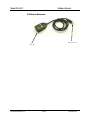
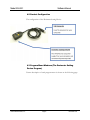
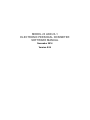
3.3 Device Structure
USB connector
IR head
Ludlum Measurements, Inc.
Page 6
November 2014
Model 23 & 23-1
4
Section
Software Manual
4.0 Descriptions and Set-ups
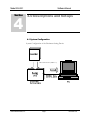
4.1 System Configuration
System Configuration of the Dosimeter Setting Device
IR communication (IrDA-1.0)
Ludlum Measurements, Inc.
Page 7
November 2014
Model 23 & 23-1
Software Manual
4.2 Product Configuration
The configuration of the Dosimeter Setting Device
4.3 Program Menu Windows (The Dosimeter Setting
Device Program)
Feature description of each program menu is shown on the following page:
Ludlum Measurements, Inc.
Page 8
November 2014
Model 23 & 23-1
Ludlum Measurements, Inc.
Software Manual
Page 9
November 2014
Model 23 & 23-1
Software Manual
4.4 Setting Up
Set up the software first, then the hardware.
Required for setup:
Dosimeter setting device
PC
1 set
1 set
Software Setups
1. Place the program installation CD in the CD-ROM drive on the PC.
2. Launch “Setup.exe” file in the “NRF_Tool” folder.
Hardware Setups
1. Insert the USB connector of Dosimeter Setting Device into the USB
port on your computer.
Note: If USB ports on your computer were already occupied with a mouse
or modem, you are required to take one of them off or add a USB port to the
computer.
Ludlum Measurements, Inc.
Page 10
November 2014
Model 23 & 23-1
5
Section
Software Manual
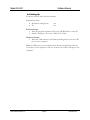
5.0 Operational Instructions
5.1 Starting the Program
1. Select the icon [NRF_Tool(Sv)Eng_R]
Start up the program.
2. When the software and dosimeter setting device program start running,
the Version window will appear.
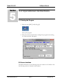
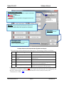
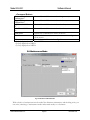
5.2 Screen Interface
The fields and buttons on the following screen are common to all windows. See
the following sections for details of each window.
Ludlum Measurements, Inc.
Page 11
November 2014
Model 23 & 23-1
Software Manual
Transmission status signal
Indicates communication status between computer & dosimeter.
Blue: Communicating,
Red Blinking: End/Disconnect,
Blank: Initializing
* Red Blinking indicates a possible misengagement/removal of
dosimeter.
Message
Displays a message regarding the dosimeter’s status and a
transmission status between the computer and a dosimeter.
Exit button
Exits from this window.
Read again button
Orders to restart a communication (and
readout of data) with dosimeter.
Common features of the menu window (functions and layout)
These messages will be indicated in the Message box. The message severity is as follows:
Severity
Messages
Descriptions
1
LOW battery
Dosimeter’s battery power is critically low.
2
3
Please place dosimeter into
reader
Maintenance mode
Communication with dosimeter has not been
established yet.
Dosimeter is in maintenance mode.
4
Processed Successfully
5
Initializing...
Communication between the setting device and
dosimeter has been established.
In the process of establishing communication
between the setting device and a dosimeter.
* Note: Features on the menu will function only when the dosimeter is in communication. If
<Transmission> window is blinking Red, place/replace the dosimeter into the reading unit, and
then click <Read again> button. Data communication will be started/resumed, and
<Transmission> will be Blue.
Ludlum Measurements, Inc.
Page 12
November 2014
Model 23 & 23-1
Software Manual
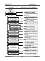
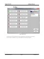
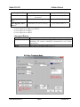
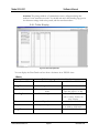
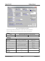
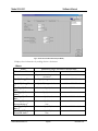
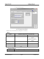
5.3 Menu
Figure 5-1 Menu screen
All functions that are performed via data communication with dosimeters are listed.
You can select one function to go to the window of the function selected.
Ludlum Measurements, Inc.
Page 13
November 2014
Model 23 & 23-1
Software Manual
<Menu Button>
Dosimeter Settings
Indication Display
Data Trending Mode
Manual Calibration
Maintenance Mode
System Settings
Client Control No.
Dosimeter Data Reset
Dosimeter Settings (dose
rate)
Counts Readout
Entry/Exit retention data
Information data
Goes to the next window: Fig. 5-2
Goes to the next window: Fig. 5-3
Goes to the next window: Fig. 5-4
Goes to the next window: Fig. 5-5
Goes to the next window: Fig. 5-6
Goes to the next window: Fig. 5-7
Goes to the next window: Fig. 5-8
Goes to the next window: Fig. 5-9
Goes to the next window: Fig. 5-10
Goes to the next window: Fig. 5-11
Goes to the next window: Fig. 5-12
Goes to the next window: Fig. 5-13
<Command Button>
Read again*
Re-starts communication with a dosimeter. If it starts communication
by establishing transmission, it processes data read out automatically.
*: This is indicated while communication is not established.
Exit
Closes the current window
Ludlum Measurements, Inc.
Page 14
November 2014
Model 23 & 23-1
Software Manual
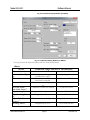
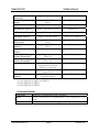
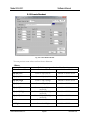
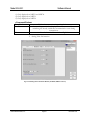
5.4 Dosimeter Settings
Fig. 5-2-1 Dosimeter Settings Window (for NRF30, NRF40 or Dose-i)
Ludlum Measurements, Inc.
Page 15
November 2014
Model 23 & 23-1
Software Manual
Fig. 5-2-2 Dosimeter Settings Window (for NRF31)
The user can display the configurations read out from the dosimeter. You can also edit the
configuration, and then write the values to the dosimeter.
<View>
Name
Client Control No.
Definition, range and unit of the functions
Dosimeter ID
000001 to 999999
<Setting>
Name
Alarm Duration
Timer Set
Runtime Display
Monitoring Beep Step
Data Trending
Interval
Ludlum Measurements, Inc.
Definition, range and unit of the functions
Alarm duration length
1 to 9 min
Alarm activation when the work
time limit is exceeded.
Mode selection for indicating
operation time.
Beep activation intervals
according to the dose increment.
Data Trending intervals
0000h:01min to 9999h:59min
Page 16
Count down
Count up
OFF / 0.001 / 0.002 / 0.01 /
0.1 mSv
15 sec/ 30sec/ 1 min/ 5
min/ 10 min/ 30 min/ 60
min/ 90 min
November 2014
Model 23 & 23-1
Trend Format
Self Check Mode
Self Check Duration
Return Reminder
Readout Trend
Stop Alarm
Data Trending
Mode*1
Addition Alarm by
Dose Type *1
Software Manual
Shifts the decimal point for data
trending.
Enables/ disables Self check, and
sets the check count value.
Decision time for Self check.
Alarm to remind to return a
dosimeter.
Enables/ disables data acquisition
through a dedicated external
device.
Enables/ disables the button on
the dosimeter for alarm
cancellation.
Selection of the trend data
storage format by dose type.
Dose type for cumulative dose.
00.00 / 000.0 mSv
OFF /
1/3/5/10/20/40/80/100
count
1 to 10 minutes.
(Note) The time is displayed
except when the feature is
disabled.
ON / OFF
ON / OFF
ON / OFF
Hp(10)g Hp(10)n/ Hp(10)g
Hp(10)g Hp(10)n/ Hp(10)g
*1: Indicated only on NRF31 and NRF34
<Command Button>
Com_End
Finishes the communication with a dosimeter.
Write
Updates the dosimeter in communication to the configurations on the
screen.
Menu
Goes back to the Menu window: Fig. 5-1
Ludlum Measurements, Inc.
Page 17
November 2014
Model 23 & 23-1
Software Manual
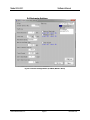
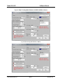
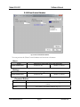
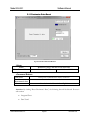
5.5 Indication Display
Fig. 5-3-1 Indication Display Window (for NRF30, NRF 40 and Dose-i)
Ludlum Measurements, Inc.
Page 18
November 2014
Model 23 & 23-1
Software Manual
Fig. 5-3-2 Indication Display Window (for NRF31)
Fig. 5-3-3 Indication Display Window (for NRF34)
You can preview the measured values read out from the dosimeter.
<View>
Name
Client Control No.
Alarm by Dose Type
*1
Timer Set
Gamma Calib. Const.
nf Calib. Const.
nth Calib. Const.*2
Hp(10) Integ. Dose
Hp(10)n Integ. Dose
*2
Hp(0.07) Calib.
Const.*3
nf Integ. Dose *2
Ludlum Measurements, Inc.
Definition, range and unit of the functions
Dosimeter ID.
000001 to 999999
Alarm output according to the
provided dose type(s)
Alarm activation when the work
time limit is exceeded.
Calibration constant for gammaray
Calibration constant for neutron
Hp(10)g alarm
0000h:01min to 9999h:59min
Gamma: 60 to 160%
nf, nth: 20 to 255%
Integrated dose of gamma-ray.
0.0 to 9999.999 mSv
Integrated dose neutron
0.0 to 9999.999 mSv
Calibration constant for Hp(0.07)
Hp(0.07): 60 to 160%
Integrated dose of nf.
0.0 to 9999.999 mSv
Page 19
November 2014
Model 23 & 23-1
Software Manual
nth Integ. Dose *2
Integrated dose of nth.
Runtime
Max Hp(10) Dose
Rate
Max Hp(0.07) Dose
Rate *3
0.0 to 9999.999 mSv
Operation time length of the
0000 h 00 min to 99 h 59 min
dosimeter.
Maximum dose rate of gamma-ray
0.0 to 9999.99 mSv/ h
Maximum dose rate of beta-ray
0.0 to 9999.99 mSv/ h
*1) Only displayed on NRF31 and NRF34.
*2) Only displayed on NRF31.
*3) Only displayed on NRF34.
<Command Button>
Com_End
Finishes the communication with a dosimeter.
Read
Starts reading out for data display. This will be executed from
initializing the already established communication even during
transmission.
Menu
Goes back to the Menu window: Fig. 5-1
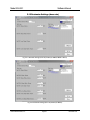
5.6 Data Trending Mode
Ludlum Measurements, Inc.
Page 20
November 2014
Model 23 & 23-1
Software Manual
Fig. 5-4-1 Data Trending Mode Window (for NRF30, NRF40 or Dose-i)
Fig. 5-4-2 Data Trending Mode Window (for NRF31)
Ludlum Measurements, Inc.
Page 21
November 2014
Model 23 & 23-1
Software Manual
Fig. 5-4-3 Data Trending Mode Window (for NRF34)
You can preview the trend data read out from the dosimeter.
<View>
Name
Client Control No.
Definition, range and unit of the functions
Dosimeter ID.
000001 to 999999
Data Trendings
The total of the variations of a
One dose type: 1 to 600
trend.
Two dose types: 1 to 300
Data
Trending Data Trending intervals
15 sec/ 30sec/ 1 min/ 5
Interval
min/ 10 min/ 30 min/ 60
min/ 90 min
Trend Format
Shifts the position of decimal
00.00 / 0.000 mSv
point for data trending.
Data Trending Mode Selection of the trend data storage Hp(10)g, Hp(10)n / Hp(10)g
format by dose type.
Hp(10) Integ. Dose
Integrated dose of gamma-ray
0.0 to 9999.999 mSv
Hp(0.07)
Integ. Integrated dose of neutron
3
Dose*
nf Integ. Dose*2
Integrated dose of nf.
0.0 to 9999.999 mSv
nth Integ. Dose*2
Integrated dose of nth.
0.0 to 9999.999 mSv
Runtime
Operation time length of the
dosimeter
Unit to be used.
Unit*1
0.0 to 9999.999 mSv
0000 h 00 min to 9999 h 59
min
mSv, mrem
*1) Unit of measurement can be switched for NRF series by this configuration. Regarding
Dose-i, please don’t change this configuration simply since the unit of measurement is
printed on the surface of dosimeter. When unit of measurement of Dose-i is changed, both
configuration and surface label shall be changed.
*2) Only displayed on NRF31.
*3) Only displayed on NRF34.
<Command Button>
Table Display
Reads out the Data Trend, and then goes to the next window: Fig. 5-4-4
Graph Display
Reads out the Data Trend, and then goes to the next window: Fig. 5-4-5
Com_End
Finishes the communication with a dosimeter.
Read
Starts reading out for data display. This will be executed from initializing
the already established communication even during transmission.
Menu
Goes back to the Menu window: Fig. 5-1
Ludlum Measurements, Inc.
Page 22
November 2014
Model 23 & 23-1
Software Manual
Attention: The prompt window <Communication error> will appear during data
readout if a new trend does not exist. You should wait until a data trending step given in
the dosimeter settings window has passed, and then start data readout.
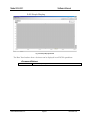
5.6.1 Table Display
Fig. 5-4-4 Table Display Window
You can display the Data Trend read out from a dosimeter in an EXCEL sheet.
<View>
Name
Client Control No.
Definition, range and unit of the functions
Dosimeter ID
000001 to 999999
Integ. Dose
Integrated dose
0.0 to 9999.999 mSv
The total of the variations of a
trend
Data creating intervals
One dose type: 1 to 600
Two dose types: 1 to 300
15 sec/ 30sec/ 1 min/ 5
min/ 10 min/ 30 min/ 60
min/ 90 min
00:00:00 to 99:99:99
Trend number
Trending Interval
Time
Elapsed time
Time Dose
Dose per trend pitch duration
Integ. Dose
Integrated value of time dose
Ludlum Measurements, Inc.
Page 23
0.0 to 99.99 mSv
or 0.000 to 9.999 mSv
0.0 to 9999.999 mSv
November 2014
Model 23 & 23-1
Software Manual
5.6.2 Graph Display
Fig. 5-4-5 Graph Display Window
The Data Trend readout from a dosimeter can be displayed in an EXCEL spreadsheet.
<Command Button>
End
Ludlum Measurements, Inc.
Close this Graph Display window.
Page 24
November 2014
Model 23 & 23-1
Software Manual
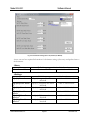
5.7 Manual Calibration
Fig. 5-5-1 Manual calibration Window (for NRF30, NRF40 or Dose-i)
Fig. 5-5-2 Manual calibration Window (for NRF31)
Ludlum Measurements, Inc.
Page 25
November 2014
Model 23 & 23-1
Software Manual
Fig. 5-5-3 Manual calibration Window (for NRF34)
Here preview integrated dose and calibration constant read out from a dosimeter.
Edit the configuration directly, and then write the values to the dosimeter.
<View>
Name
Client Control No.
Calib. Const.
Integ. Dose
<Setting>
Name
Calib. Const.
Ludlum Measurements, Inc.
Definition, range, and unit of the functions
Dosimeter ID
000001 to 999999
Calibration constant read out
from a dosimeter.
(for gamma/ nf / nth rays)
Integrated dose
(for gamma/ nf / nth rays)
Gamma: 60 to 140%
nf, nth: 20 to 255%
(Unit: 1)
0.0 to 9999.999mSv
Definition, range, and unit of the functions
Update value of dose to be
Gamma: 60 to 140%
written to a dosimeter.
nf, nth: 20 to 255%
(for gamma/ nf / nth rays)
(Unit: 1)
Page 26
November 2014
Model 23 & 23-1
Software Manual
<Command Button>
Gamma Manual
Calibration *1
Hp(0.07)Manual
Calibration *3
nf Manual Calibration
*2
nth Manual Calibration
*2
Com_End
Write
Goes to Manual Calibration window for gamma ray.
Goes to Manual Calibration window for beta ray.
Goes to Manual Calibration window for nf ray.
Goes to Manual Calibration window for nth ray.
Finishes the communication with a dosimeter.
Updates the dosimeter in communication to the configurations
on the screen.
Menu
Goes back to the Menu window: Fig. 5-1
*1) Only displayed on NRF31 and NRF34.
*2) Only displayed on NRF31.
*3) Only displayed on NRF34.
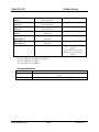
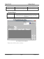
5.8 Maintenance Mode
Fig. 5-6 Maintenance Mode Window
With selection of maintenance mode needed for dosimeter maintenance and checking work, you
can write (switching of maintenance mode and normal mode) to a dosimeter.
Ludlum Measurements, Inc.
Page 27
November 2014
Model 23 & 23-1
Software Manual
<View>
Name
Client Control No.
Definition, range and unit of the functions
Dosimeter ID
000001 to 999999
<Setting>
Name
LCD Check Mode
Definition, range and unit of the functions
Turn on all LCDs.
Count Value Display
Mode
Buzzer Volume Check
Mode
Exit Maintenance
Indication of internal counter
Activation of continuous buzzer
Cancelation of maintenance mode (switching to normal
mode)
<Command Button>
Com_End
Finishes the communication with a dosimeter.
Write
Updates the dosimeter in communication to the configurations on the
screen.
Menu
Goes back to the Menu window: Fig. 5-1
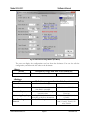
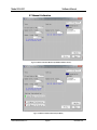
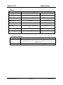
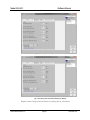
5.9 System Setting
Fig. 5-7-1 System Setting Window (for NRF30, NRF40 or Dose-i)
Ludlum Measurements, Inc.
Page 28
November 2014
Model 23 & 23-1
Software Manual
Fig. 5-7-2 System Setting Window (for NRF31)
Preview integrated dose and calibration constant read out from a dosimeter.
Edit the configuration directly, and then write the values to the dosimeter.
<View>
Name
Client Control No.
<Setting>
Name
Serial No.
Time Constant
Return Remind Time
Definition, range and unit of the functions
Dosimeter ID
000001 to 999999
Definition, range and unit of the functions
Setting of dosimeter ID
Display only
Setting of gamma constant
Buzzer Frequency
Reminder time not to forget to
get the dosimeter back
Setting of the buzzer frequency
Gamma Correction
Factor1
nthb Correction
Factor1*2
Setting of Gamma correction
factor
Setting of nthb correction factor
1
Ludlum Measurements, Inc.
Page 29
1 to 80
(Step: 1)
1 to 99
(Step: 1)
1 to 255
(Step: 1)
0.0 to 7.9 (Step: 0.1)
3.0 to 9.9 (Step: 0.1)
November 2014
Model 23 & 23-1
Software Manual
nthb Correction
Factor2*2
Gamma Detector
Factor
nf Detector Factor *2
Setting of nthb correction factor
2
Setting of gamma Detector
factor
Setting of nf detector factor
4.0 to 9.9 (Step: 0.1)
nth Detector Factor *2
Setting of nth detector factor
Display only
nf Correction Factor *2
Setting of nf correction factor
0.000 to 10.00 (Step: 0.001)
Setting of nf safety factor
0.0 to 127.5 (Step: 0.5)
Setting of Hp (0.07) correction
factor
Setting of Hp (0.07) detector
factor
Determined time of Hp (0.07)
0.000 to 50.000 (Step: 0.001)
Hp (0.07) gamma correction
factor 2(f)
Hp (0.07) gamma correction
factor (E)
Enable/disable initialization of
integrated dose data with
insertion of a reset pin.
ON/OFF of rounding off for
integrated dose.
Enable/disable soundness check
for gamma detector
2.0 to 7.0 (Step: 0.1)
nth Safety Factor *2
Hp (0.07) Correction
Factor (C) *3
Hp(0.07) Detector
Factor *3
Hp (0.07)Subtract-hold
Time *3
Hp (0.07) G-Count
Correct Factor2(f) *3
Hp (0.07) G-Count
Correct Factor2(E) *3
Clear Dose Mode
Round Off Dose
Health Check for
Gamma
Display only
Display only
Display only
OFF / ON
0.000 to 9.000 (Step: 0.001)
OFF / ON
OFF / ON
OFF / ON
*1) Only displayed on NRF31 and NRF34.
*2) Only displayed on NRF31.
*3) Only displayed on NRF34.
<Command Button>
Com_End
Finishes the communication with a dosimeter.
Write
Updates the dosimeter in communication to the configurations on the
screen.
Menu
Goes back to the Menu window: Fig. 5-1
Ludlum Measurements, Inc.
Page 30
November 2014
Model 23 & 23-1
Software Manual
5.10 Client Control Number
Fig. 5-8 Client Control Number Window
You can preview the Client Control Number read out from a dosimeter.
<View>
Name
Client Control No.
Definition, range and unit of the functions
Dosimeter ID
000001 to 999999
<Setting>
Name
Client Control No.
Definition, range and unit of the functions
Dosimeter ID
000001 to 999999
<Command Button>
Com_End
Finishes the communication with a dosimeter.
Write
Updates the dosimeter in communication to the configurations on the
screen.
Menu
Goes back to the Menu window: Fig. 5-1
Ludlum Measurements, Inc.
Page 31
November 2014
Model 23 & 23-1
Software Manual
5.11 Dosimeter Data Reset
Fig. 5-9 Dosimeter Data Reset Window
<View>
Name
Client Control No.
<Command Button>
Com_End
Reset
Dosemeter’s data
Menu
Definition, range, and unit of the functions
Dosimeter ID
000001 to 999999
Finishes the communication with a dosimeter.
Resets information on a dosimeter.
Goes back to the Menu window: Fig. 5-1
Attention: By clicking “Reset Dosimeter’s Data,” the following data will be deleted. Process it
with caution.
Integrated Dose
Data Trend
Ludlum Measurements, Inc.
Page 32
November 2014
Model 23 & 23-1
Software Manual
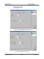
5.12 Dosimeter Settings (dose rate)
Fig. 5-10-1 Dosimeter settings (dose rate) window (for NRF30, NRF40 or Dose-i)
Fig. 5-10-2 Dosimeter settings (dose rate) window (for NRF31)
Ludlum Measurements, Inc.
Page 33
November 2014
Model 23 & 23-1
Software Manual
Fig. 5-10-3 Dosimeter settings (dose rate) window (for NRF34)
A user can read out required information for dosimeter settings (dose rate) and update them to
the dosimeter.
<View>
Name
Client Control No.
Definition, range, and unit of the functions
Dosimeter ID
000001 to 999999
<Setting>
Name
Hp (10) Dose Alarm
Hp (0.07) Dose Alarm
*3
Hp (10)n Dose Alarm
*2
Hp (10) Dose Rate
Alarm
Hp (0.07) Dose Rate
Alarm *3
Hp (10)n Dose Rate
Alarm *2
Ludlum Measurements, Inc.
Definition, range, and unit of the functions
Hp (10) integrated dose alarm
threshold
Hp (0.07) integrated dose alarm
threshold
Hp (10)n integrated dose alarm
threshold
Hp (10) dose rate alarm threshold
Hp (0.07) dose rate alarm
threshold
Hp (10)n dose rate alarm
threshold
Page 34
0.001 to 9999.999 mSv
0.001 to 9999.999 mSv
0.01 to 9999.99 mSv/ h
0.01 to 9999.99 mSv/ h
0.001 to 9999.999 mSv
0.001 to 9999.999 mSv
November 2014
Model 23 & 23-1
Hp(10) Pre Dose
Alarm
Hp(0.07) Pre Dose
Alarm *3
Hp(10)n Pre Dose
Alarm *2
Hp(10) Pre Dose Rate
Alarm
Hp(0.07) Pre Dose
Rate Alarm *3
Hp(10)n Pre Dose
Rate Alarm *2
Name
Software Manual
Hp (10) integrated dose pre
alarm threshold
Hp (0.07) integrated dose pre
alarm threshold
Hp (10)n integrated dose pre
alarm threshold
Hp (10) dose rate pre alarm
threshold
Hp (0.07) dose rate pre alarm
threshold
Hp (10)n dose rate pre alarm
threshold
User name
0.001 to 9999.999 mSv
0.001 to 9999.999 mSv
0.01 to 9999.99 mSv/ h
0.01 to 9999.99 mSv/ h
0.001 to 9999.999 mSv
0.001 to 9999.999 mSv
8 alphanumeric characters
(capital)
Note) Indicates up to 8
characters on dosimeter’s
display.
*1) Only displayed on NRF31 and NRF34.
*2) Only displayed on NRF31.
*3) Only displayed on NRF34.
<Command Button>
Com_End
Finishes the communication with a dosimeter.
Write
Updates the dosimeter in communication to the configurations on the
screen.
Menu
Goes back to the Menu window: Fig. 5-1
Ludlum Measurements, Inc.
Page 35
November 2014
Model 23 & 23-1
Software Manual
5.13 Counts Readout
Fig. 5-11 Counts Readout window
You can preview count values read out from a dosimeter.
<View>
Name
Client Control No.
Definition, range and unit of the functions
Dosimeter ID
000001 to 999999
Hp (10) Low
Count of Hp (10)Low
000000 to 999999 count
Hp (10) Mid
Count of Hp (10)Mid
000000 to 999999 count
Hp (10) High
Count of Hp (10)High
000000 to 999999 count
Count of Hp (10)ck
000000 to 999999 count
000000 to 999999 count
nf Low
Count of Hp (0.07) Low
(reserved)
Count of Hp (0.07) High
(reserved)
Count of Hp (0.07) High
(reserved)
Count of nf Low
nf High
Count of nf High
000000 to 999999 count
Hp (10) ck
Hp (0.07) Low
Hp (0.07) High
Hp (0.07) ck
Ludlum Measurements, Inc.
Page 36
000000 to 999999 count
000000 to 999999 count
000000 to 999999 count
November 2014
Model 23 & 23-1
Software Manual
nth Low
Count of nth Low
000000 to 999999 count
nth High
Count of nth High
000000 to 999999 count
<Command Button>
Com_End
Finishes the communication with a dosimeter.
Read
Starts reading out for data display. This will be executed from
initializing the already established communication even during
transmission.
Menu
Goes back to the Menu window: Fig. 5-1
5.14 Entry/Exit Retention Data
Fig. 5-12 Entry/Exit retention data Window
Displays entry/exit history data in a dosimeter.
Ludlum Measurements, Inc.
Page 37
November 2014
Model 23 & 23-1
<View>
Name
Client Control No.
Work Info. Record
Software Manual
Definition, range and unit of the functions
Dosimeter ID
000001 to 999999
Number of work info record data
0 to 500 count
ID card number
000000 to 999999
Entry Date
Entry date
YYMMDD
Entry Time
Entry time
hhmm
Operation time length of the
dosimeter
Gamma-ray integrated dose
hhhh:mm
0.001 to 9999.999 mSv
Beta-ray integrated dose
0.001 to 9999.999 mSv
ID Card No.
Runtime
Gamma Integ. Dose
Beta Integ. Dose
<Command Button>
Com_End
Finishes the communication with a dosimeter.
Read
Starts reading out for data display. This will be executed from
initializing the already established communication even during
transmission.
Menu
Goes back to the Menu window: Fig. 5-1
Ludlum Measurements, Inc.
Page 38
November 2014
Model 23 & 23-1
Software Manual
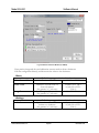
5.15 Information Data
1. Dose Information
Fig. 5-13-1 Dose Information Window (for NRF30, NRF40 or Dose-i)
Fig. 5-13-2 Dose Information Window (for NRF31)
Ludlum Measurements, Inc.
Page 39
November 2014
Model 23 & 23-1
Software Manual
Fig. 5-13-3 Dose Information Window (for NRF34)
Displays dose information by reading data in a dosimeter.
<View>
Name
Client Control No.
Runtime
Hp (10) Integ. Dose
Definition, range, and unit of the functions
Dosimeter ID
000001 to 999999
Operation time length of the
dosimeter
Hp (10) integrated dose
Hp (0.07) Integ. Dose
Hp (0.07) integrated dose
*3
Max Hp (10) Dose
Maximum Hp (10) dose rate
Rate
Max Hp (10) Occurred Maximum Hp (10) dose rate time
time *2
Max Hp (10)n Dose
Maximum Hp (10)n dose rate
Rate
Max Hp (10)n
Maximum Hp (10)n dose rate
Occurred time *2
time
Maximum Hp (0.07) dose rate
Max Hp (0.07) Dose
Rate *3
Max Hp (0.07)
Maximum Hp(0.07) dose rate
3
Occurred time *
time
Ludlum Measurements, Inc.
Page 40
hh:mm
0.000 to 9999.999 mSv
0.000 to 9999.999 mSv
0.01 to 9999.99 mSv/ h
hh:mm
0.01 to 9999.99 mSv/ h
hh:mm
0.01 to 9999.99 mSv/ h
hh:mm
November 2014
Model 23 & 23-1
Software Manual
*1) Only displayed on NRF31 and NRF34.
*2) Only displayed on NRF31.
*3) Only displayed on NRF34.
<Command Button>
Com_End
Finishes the communication with a dosimeter.
Read
Starts reading out for data display. This will be executed from
initializing the already established communication even during
transmission.
Menu
Goes back to the Menu window: Fig. 5-1
2. Setting Value Information
Fig. 5-13-4 Setting value Information Window (for NRF30, NRF40 or Dose-i)
Ludlum Measurements, Inc.
Page 41
November 2014
Model 23 & 23-1
Software Manual
Fig. 5-13-5 Setting value Information Window (for NRF31)
Fig. 5-13-6 Setting value Information Window (for NRF34)
Displays alarm setting value information by reading data in a dosimeter.
Ludlum Measurements, Inc.
Page 42
November 2014
Model 23 & 23-1
<View>
Name
Hp (10) Dose Alarm
Hp (0.07) Dose Alarm
*3
Hp (10)n Dose Alarm
*2
Hp (10) Dose Rate
Alarm
Hp (0.07) Dose Rate
Alarm *3
Hp (10)n Dose Rate
Alarm *2
Hp (10) Pre Dose
Alarm
Hp (0.07) Pre Dose
Alarm *3
Hp (10)n Pre Dose
Alarm *2
Hp (10) Pre Dose
Rate Alarm
Hp (0.07) Pre Dose
Rate Alarm *3
Hp (10)n Pre Dose
Rate Alarm *2
Setting time
Software Manual
Definition, range, and unit of the functions
Hp (10) integrated dose alarm
0.001 to 9999.999 mSv
threshold
Hp (0.07) integrated dose alarm
0.001 to 9999.999 mSv
threshold
Hp (10)n integrated dose alarm
0.01 to 9999.99 mSv/ h
threshold
Hp (10) dose rate alarm threshold
0.01 to 9999.99 mSv/ h
Hp (0.07) dose rate alarm threshold
0.001 to 9999.999 mSv
Hp (10)n dose rate alarm threshold
0.001 to 9999.999 mSv
Hp (10) integrated dose pre alarm
threshold
Hp (0.07) integrated dose pre alarm
threshold
Hp (10)n integrated dose pre alarm
threshold
Hp (10) dose rate pre alarm threshold
0.001 to 9999.999 mSv
Hp (0.07) dose rate pre alarm
threshold
Hp (10)n dose rate pre alarm
threshold
Alarm setting time
0.001 to 9999.999 mSv
0.01 to 9999.99 mSv/ h
0.01 to 9999.99 mSv/ h
0.001 to 9999.999 mSv
0.001 to 9999.999 mSv
hh:mm
*1) Only displayed on NRF31 and NRF34.
*2) Only displayed on NRF31.
*3) Only displayed on NRF34.
<Command Button>
Com_End
Finishes the communication with a dosimeter.
Read
Starts reading out for data display. This will be executed from
initializing the already established communication even during
transmission.
Menu
Goes back to the Menu window: Fig. 5-1
Ludlum Measurements, Inc.
Page 43
November 2014
Model 23 & 23-1
Software Manual
3. Entry/Exit Information
Fig. 5-13-7 Entry/Exit Information Window
Displays entry/exit information by reading data in a dosimeter.
<View>
Name
ID Card No.
Definition, range, and unit of the functions
ID card number
000000 to 999999
Name.
User name
Entry Date
Entry date
8 alphanumeric characters
(capital)
Note) indicate up to 8
characters on dosimeter’s
display.
YYMMDD
Entry Time
Entry time
hhmm
Number of work information
record
0 to 10 count
Work Info. Record
<Command Button>
Name
Com_End
Ludlum Measurements, Inc.
Definition, range, and unit of the functions
Finishes the communication with a dosimeter.
Page 44
November 2014
Model 23 & 23-1
Read
Menu
Ludlum Measurements, Inc.
Software Manual
Starts reading out for data display. This will be executed from
initializing the already established communication even during
transmission.
Goes back to the Menu window: Fig. 5-1
Page 45
November 2014
Model 23 & 23-1
6
Section
Software Manual
6.0 Troubleshooting
6.1 Errors and Solutions
Transmission Error – communication error between a computer and a
Dosimeter Setting Device.
During computer startup, processing, or data communication:
Error
Suggested Solution
<Establishing communication>
Reading unit, or cable abnormal
<Status Process>
No response
Check the cable connection.
Check the cable connection.
During data readout from a dosimeter.
Error
<Reading Process (trend data
acquisition)> Dosimeter not
communicating
<Reading Process (trend data
acquisition)> Dosimeter
communication error
<Reading Process (trend acquisition
data acquisition)> No response
<Trend data rending process> Trend
data does not exist
Suggested Solution
Retry reading out.
Retry reading out.
Check the dosimeter setting device.
Check the connection with USB
cable.
No trend data. Create data first, and
then read out.
During writing configurations to the dosimeter.
Error
<Writing Process>
No response
<Writing Process>
Dosimeter communication error
Ludlum Measurements, Inc.
Page 46
Suggested Solution
Process reading out, first.
Process reading out, first.
November 2014
Model 23 & 23-1
Software Manual
<Writing Process>
No response
Process reading out, first.
Check the cable connection.
Note: Please restart PC if the errors not listed in this section occurred.
Internal Error - Errors detected by an internal check.
All starting of writing/occurrence of abnormality on configuration range:
Error
Input Error of xxxx
Suggested Solution
Re-enter the value within the valid
range.
Error during communication start – Errors detected by a computer internal
check when attempted to write or to read out trend data.
When attempting the writing process.
Error
Dosimeter not communicating, cannot
write.
Suggested Solution
Start reading process, first.
Error when attempted to reading out trend data:
Error
Dosimeter not communicating.
Suggested Solution
Cancel the trend data readout, and
then start regular reading process.
Note: Please restart PC if the errors not listed in this section occurred.
Ludlum Measurements, Inc.
Page 47
November 2014
Model 23 & 23-1
7
Section
Software Manual
7.0 Abnormalities
Problem
Cannot establish communication.
Ludlum Measurements, Inc.
Page 48
Solution
Process reading out, first.
Check the cable connection.
Please contact Ludlum Measurements
if experiencing frequent transmission
errors.
November 2014
Model 23 & 23-1
8
Section
Software Manual
8.0 Maintenance
Check the Dosimeter Setting Device as specified below to ensure its
performance.
To be checked:
External appearance
Cable connection
Infrared communication
Ludlum Measurements, Inc.
Page 49
Procedure
Visual check for any foreign objects
such as dirt or dust balls.
Check every six months, or every time
a transmission error occurs.
Check point; inside of USB port.
Check any looseness on connection of
cables.
Check every six months, or every tiem
a transmission error occurs.
Check point; cables.
Put close dosimeter to the IR head and
check the transmission.
Check every six months, or every time
a transmission error occurs.
November 2014