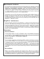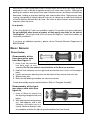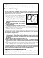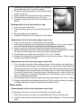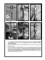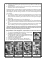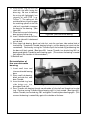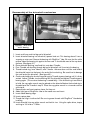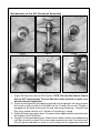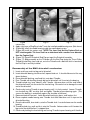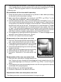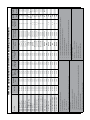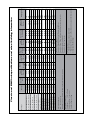
1
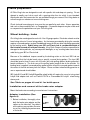
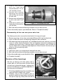
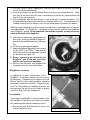
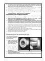
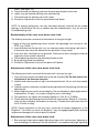
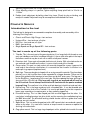
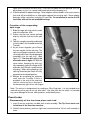
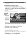
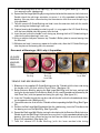
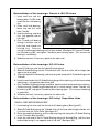
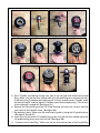
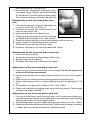
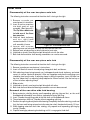
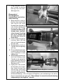
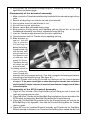
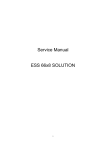
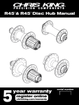
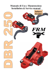
Hub Service Manual
for Shop Mechanics
Part #17990 rev.11/14
Complete instructions for servicing
Chris King ISO and Classic hubs.
Includes answers to common technical questions
and use of the Chris King hub service tool.
King Cycle Group
2801 NW Nela Street; Portland, Oregon 97210
For technical questions, call 800.523.6008
www.chrisking.com
HUBSETS
This manual is intended for the mechanic who already possesses a familiarity with hubset
adjustment techniques and who are interested in the learing how to completely overhaul their
Chris King Classic or ISO hubsets.
Features
• Classic,HighFlange,ISODisc,singlespeed,andtandemhubsavailable
• ExclusivepatentedRingDrive™ engagement system offers 72 points of instant and positive
engagementandextremlyhightorquecarryingcapacityidealforhardracing,tandems,
etc.
• Bearingsarefullyserviceableandareavailableineithersteelorceramicoptions
• Strongandstiff19.5mmaxles
• In-housedesignandmanufacturing-100%madebyChrisKingintheUSA
• Unparalleledqualityandreliability
• Responsiblylightweight
set-up
GettinG started
and
Cautions
The following issues that are important to review before servicing and/or trouble shooting your
Chris King hub:
Adjust the preload on the bearings directly after building the
wheel
Spoke tension pulling out on the flanges can slightly loosen the preload adjustment on the
bearings.Thehub(s)comepre-adjustedfromthefactoryanticipatingbothspoketensionand
skewer compression. However, because of variations in wheel-building practices, a minor
adjustment should always be performed upon completion of the wheel build. Please see the
appropriate “adjustment” section and check the hub before using.
Chris King hubs feature adjustable bearing preload
Thebearingsshouldbekeptinproperadjustmentforoptimumproductperformance.Donot
allow the adjustment to become loose, as this may cause a loss of performance that could
lead to damage to the hubs.
2
Rev. 11/14
Use steel quick releases for maximum rigidity
Our19.5mmaxleisoneofthestiffestavailable.However,performancewillbemaximizedwith
the stiffest possible attachment to the frame or fork. Some Chris King hubs are designed to be
usedinconjunctionwithquick-releaseskewers.Itisrecommendedthattheskewerdevelop
a minimum of 1100 lb. of clamping force when set. For best performance, use a steel skewer.
Titanium skewers are not recommended.
Use only the recommended bolts with our bolt-on hubs
Never use thread locking or mounting compounds
Thread locking compounds are not an acceptably reliable substitution for loose threads or press
fitsinhighperformancecomponentry.AllChrisKingcomponentsarepreciselyengineered
toexactingtolerancestoeliminatetheneedforthreadlockingcompounds.
Use “spidered” cassettes with our aluminum driveshells
The aluminum driveshells of the rear hubs are softer than the steel driveshells, and we
recommendtheuseof“spidered”-stylecassettes.Avoidusing“individual”-stylecogsetswith
the aluminum driveshells. Normal notching from individual cog wear should be knocked down
with a file.
General cautions
When using any Chris King product in conjunction with other manufacturers’ parts, be sure
to follow all manufacturers’ instructions and recommendations.
Donotattempttomodifyyourhubtoacceptanytypeofbolt-onretentiondeviceoutsideof
availableChrisKingaxlesystems.
Break-in & Wheel BuildinG
Break-in
Once your new hub is placed in service, some settling will occur. Check adjustment by clamping
wheelintoframeorfork.Ridefor5-10minutes,checkforplayorbinding,andreadjustif
necessary.Recheckafterthefirst5-10milesofriding.Checkcoglockringonrearhubs
after their first use, and tighten if necessary. Continue monitoring for the first 60 hours of use.
Duringthefirst60hoursofuse,expectsomebreak-indrag.Thisisnormalasthesealsbreak
in,andwillsoondiminish.Ifthiscauseschainsagintherearwhileback-pedaling,increase
thep-tension(cagetension)ontherearderailleur.
Thebearinggreaseisintentionallyoverpackedandexcessgreasemayseepatthebearing
sealsduringthebreak-inperiod.
Rev. 11/14
3
Frame preparation
AllChrisKinghubsaredesignedtoworkwithspecificforkanddropoutspacing.Donot
attempt to modify your hub to work with a spacing other than for which it was intended.
AftermarketaxlesandconversionkitsareavailablethroughyournearestChrisKingdealeror
online thorugh our webstore at www.chrisking.com.
Checkforkandframe dropoutstoensuretheyareparalleltoeachother.Useanapproriate
tool such as those made by Park™ or Campagnolo™.Unparalleldropoutsmaybeunsafeand/
or compromise the performance of your Chris King hub.
Wheel building - hubs
ChrisKinghubsaredesignedtoworkwith14or15gaugespokes.Discbrakewheelsmustbe
lacedusingatleasta2-crosslacingpattern.Asthetorquegeneratedbydrivingthecassette
requiresacrossedspokes,sodoestheadditionaltorqueonthenon-drivesideflangegenerated
by the braking action. Radial lacing your ISO and Classic hub is considered outside of
the intended use and will void your warranty. King Cycle Group will not be responsible for
damaged or distroyed hubs, any consequential damages, or any resulting labor costs due to
radial lacing your ISO or Classic hub.
Because of the additional torque caused by the braking action on the front ISO hub we
recommend that the hub be laced using a specific crossed lacing pattern. The front ISO
shouldbelacedatleast2-crosswiththerotor(left)sidepullingspokes(brakingdirection)
headsout/elbowsin.Thefinalcrossofthepullingspokeneedstobeontheoutside.As
braking force is applied, increased pulling spoke tension will pull the crossed spokes towards
the center of the hub and away from the caliper. Please use best wheel building practice or
seeanexperiencedwheelbuilder.
ISOLefty®LDandISOLefty®SuperMaxwheelbuildswillrequiretheuseofatruingstand
Lefty® hub adapter tool such as Park’s® TS-TA or Cannondale’s® Lefty® wheel-truing
dummyaxle.
See Table on pages 40 and 41 for build specs.
Installation and removal of the brake rotor adaptor
Mountthebrakerotoraccordingtomanufacturer’sinstructions.
Adapter installation (See
figure 6)
1. Beforeinstallation,thoroughlyclean
both the brake rotor adaptor and the
splinesonthehubshell.Anydebris
on the splines may not allow the rotor
to run true, inhibiting the performance
of the brake.
Figure6-installrotoradaptor
4
Rev. 11/14
2. Place the adaptor onto the splines. When snug, the adaptor should leave an even gap
approximatelythewidthofapieceofpaperbetweenthehubandtheadaptor.
3. Insert the three bolts provided. In an alternating pattern, hand tighten adaptor bolts to
pull adaptor down evenly.
4. Finishtorqueto28in.-lbor3.16Nm.Donotovertighten.
Adaptor removal
1. Removethediscbrakerotorifitcoversthethreemountingbolts.
2. Removethethreeadaptorfixingbolts.
3. To remove the rotor adaptor from the tapered splines, pry between the adaptor and the hub
usingtwoopposingplastictirelevers.(itshouldpopoffeasily).Donotusemetalobjects,
such as screw drivers, to release the adaptor.
Wheel building - BMX
Cautions
ChrisKingBMXhubsaresuppliedwith3/8”-16x1”socketcapaxlebolts.Replacementscan
bepurchasedatmosthighqualityhardwarestores.Useaboltofgrade8orequivalent.Under
nocircumstance,shouldaquickreleaseskewerbesubstitutedfortheaxlebolts.
DonotusecogsotherthanBMXcogs.Thedriveshelloftherearhubhasauniquesymmetrical
spline,andincompatiblewithsomeShimano,andotheraftermarketcogs.Useofothercogs
may cause chain slippage, or derailment, which could lead to bodily injury.
Installation and removal of the Cog
ChriskingBMXhubsuseacassettestylecogmountingsystem.Specialsplinesandlock
ringshavebeendesignedtoacceptpremiumqualitysteelcogs.Cogsareavailableinsizes
from12tto20t.Usingstandardcassettetoolsyoucaneasilyremoveandchangeyourcogs.
Cog installation
1. Selectdesiredtooth-countCog.
2. Slide cog onto driveshell spline. Cogs are symmetrical, and can be installed with either
side out.
3. Thread lock ring onto driveshell over cog.
4. InsertShimanoHG™-styletoolintolockring,andtightento20ft.-lbor27.12Nm.
Cog removal
1.
2.
3.
4.
Usingachainwhip,holdcogstationaryfromcounterclockwiserotation.
InsertShimanoHG™-stylecassettetoolintolockring.
Loosen and remove lock ring by rotating it until it is free from driveshell.
Slide cog off of spline.
huB
Rev. 11/14
serviCe
5
MaintenanCe
sChedule
ChrisKingHubsaredesignedtoprovidelonglifeandhighperformance.Beyondanoccasional
adjustment, the only maintenance necessary is cleaning, lubricating the RingDrive™ (see
“Maintenance of the RingDrive™ & driveshell”,page6),andre-lubricatingthebearings(see
“Bearingservice”,page9).Ridingconditionswilldeterminehowoftentomaintainyourhubs.
Asabeginningguideline,yourhubsshouldbemaintainedevery6-12monthsinnormaland
dry conditions and every 3 months in wet or muddy conditions.
The bearings in your new Chris King hubs are of the highest quality available. However, all
bearings will settle and eventually wear with use. Since looseness or “play” in the bearing
assembly can develop as a result of wear, Chris King hubs have been designed with an
adjustable bearing preload mechanism and any normal play can be eliminated (see the
appropriate“...Adjustment”section).
RingDrive™ maintenance
NormalpreventativemaintenanceoftheRingDrive™ is simple and can be performed using
basictools.(See“MaintenanceofRingDrive™ & driveshell”, page 6.) In many cases, a minor
cleaning and reapplication of lubricant is all that may be necessary. Judging when to perform
thisbasicmaintenanceisdeterminedbyridingstyleandconditions.Asabeginningguideline,
yourhubsshouldbemaintainedevery6-12monthsinnormalanddryconditionsandevery3
months in wet or muddy conditions.
Lubrication
Normal conditions
Innormalridingconditions(0°-43°C),ourRingDrive™ lube is recommended for the bearings
andtheRingDrive™. Do not substitute other brands of lube, as they may be too sticky for
the helix of the RingDrive™ inhibiting proper engagement.
Cold conditions
Toensureproperengagementinsub-freezingconditions,firstbesurethatthereisnowateror
moisture inside the hubshell. The hub may require an overhaul to ensure that the hub interior
iscompletelywater-free.ThenmixthegreaseintheRingDrive™ area, especially on the helical
splinesofthedriveshell,with5-10dropsofPTFE(e.g.TriFlow™).Ifyouexpecttoberiding
in temperatures that are consistently at or below freezing replace all internal lube with a quality
10wsyntheticoil.Donotoverfill.Wereccomendusingasiliconaloil(Pedros®SynLubeor
Mobil1®)
Wet conditions
Riding in wet conditions necessitates more frequent service. Often this is as simple as
removingtheaxleanddriveshellfromthehub,removinganymoisturefrominsidethehubshell,
and applying more grease to the needle bearing. This should not replace periodic complete
disassemblyandmaintenance,especiallyinextremeorprolongedwetconditions.
6
Rev. 11/14
Note: Since it is nearly impossible to seal a hub from water and still have it spin freely, we have
designedourhubstobeabletooperatenormallywithsome waterintrusion.Althoughthe
bearings are stainless steel and will resist water induced corrosion, the lubricant will eventually
deteriorate, leading to premature bearing wear and possible failure. High-pressure spray
washing, transporting or riding the bicycle in the rain, or submersion in water while riding can
allleadtolubricantcontaminationbywater.Beawareofthesesituationsandservicemore
frequently when they occur.
In a pinch...
IfChrisKingRingDrive™ lube in not available, a quality 10w synthetic oil may be substituted.
Do not substitute other brands of grease, as they may be too sticky for the helix of
the RingDrive™.RunningthehubonoilwillcausetheRingDrive™ to be more audible, yet
functionally no different.
If you have any additional questions, please call our Technical Services Department at
800.523.6008.
BasiC serviCe
Front hubs
Disassembly of the
front two piece axle
hub (See figure 7)
Figure7-typicalfrontquickreleasehub
1. Insert 5 mm hex wrenches
into both ends of axle
assembly.*Pro Tip: Use a bench vice to hold one of the 5mm hex wrenches.
2. Holdlefthandstationaryandturnrighthandcounterclockwise1/4turnuntilassemblyis
loose.
3. Loosenandunscrewadjustingconeandaxleenduntiltheyarefreefrommainaxle.
4. Slideoutmainaxle.
5. Bothhubshellbearingassembliescannowbeaccessed.
Furtherdisassemblyrequiresspecializedtools.Referto“CompleteAssembly”.
Disassembly of the front
one piece axle hub (See
figure 8)
1. Insert a 2.5mm hex wrench into
the adjusting clamp pinch bolt, and
loosen.
2. With adjusting cone facing towards
Figure8-typicalfrontbolt-onhub
you, hold opposite end of axle
stationary, and rotate cone in a
counterclockwisedirection.After
onecompleterevolutiontheadjustingconeshouldbefreefromtheaxle.
Rev. 11/14
7
3. Slideoutaxle.
4. Bothhubshellbearingassembliescannowbeaccessed
Furtherdisassemblyrequiresspecializedtools.Referto“CompleteAssembly”.
Service of the bearings
We offer our bearings with either quality steel or ceramic balls, so short term water intrusion
should not lead to any substantial damage. Judging when to service the bearings is completely
dependent on the riding style and conditions.
1. Chris King sealed bearings have removable snap rings
that hold the rubber seals in place. (See figure 9.)
2. Carefully, using a small screwdriver, pick, or penknife,
remove the snap ring by inserting tool into split of snap
ring. Gently work one end of the snap ring toward
bearing center until it is out of its groove. Follow the
ring around with the tool until the snap ring is completely
dislodged.
3. Lift and remove exposed rubber seal to access the
Figure9-seal&snapring
interior of the bearing.
4. Thoroughly flush the bearing with a light spray lubricant
(e.g.WD-40™)andblowdry.Avoidusingcuasticcleanersandcitrusbaseddetergents.
5. Wipedirtandothercontaminantsfromthesealsandsnaprings.Avoidcleaningtheseals
with solvent, which could cause deterioration.
Note:somesolvents,syntheticlubricants,andgreaseswithhigh-pressureadditivesmayattack
anddamagesealsandothernonmetallicmaterials.Minimizeexposuretothesesubstances
and thoroughly dry hub after cleaning.
6. LayabeadofourRingDrive™ grease, filling the gap between the inner and outer races
1/3 for steel balls or 1/4 for ceramic around the large bearing and 3/4 for steel or 1/3 for
ceramic around the small bearing. Then rotate the inner race to work grease throughout
the ball area.
7. Replacerubbersealbetweeninnerandouterbearingrace.
8. Insert one edge of snap ring into groove of outer bearing race. Press along entire groove
until snap ring is fully seated; a small gap should be visible between both ends of the snap
ring.
9. Turn inner race of bearing by hand to test for binding. If bearings do not run smooth, repeat
steps1-9.Bindingisoftenaresultofimproperlyseatedsealsand/orsnaprings.
Usedsnapringsandsealscanbereinstalledunlesswarped,punctured,orotherwisedamaged.
If damaged, replacement seals and snap rings are available from your local bike shop or directly
fromChrisKingprecisioncomponentsatwww.chrisking.comor800-533-6008.
Reassembly of the front quick-release hub
1. Lightlyoilmainaxleo-ringswithlightweight,lowviscosityoil,withPTFE(e.g.TriFlow™).
2. Insertmainaxleintohubshell.
3. Threadadjustingconealongaxleenduntilasmallgapatthebeginningofthethreadsshows.
8
Rev. 11/14
4.
5.
6.
7.
Grease the adjusting cone threads with waterproof
grease (See figure 10 on the following page.)
Threadaxleendandadjustingconeontotheprotruding
threadsofmainaxle.
Lightlysnugaxleendandadjustingconeuptobearing.
Threadaxleendintoadjustingconeuntilitstops.
Proceedto“Adjustmentofthefronttwopieceaxlehub”
(below).
Reassembly of the front bolt-on hub
1. Insertmainaxleintohubshell.
2. Thread adjusting clamp onto the protruding threads of
Figure10-adjustingcone
axle.
3. Snug adjusting cone up to bearing.
4. Proceedto“Adjustmentof thefrontbolt-onhub”(below).
Adjustment of the front two piece axle hub
1. Insert5mmhexwrenchesintobothendsofaxleassembly.
2. Holdlefthandstationaryandturnrighthandcounterclockwise1/4turnuntilassemblyis
loose.*Pro Tip: Use a bench vice to hold one of the 5mm hex wrenches.
3. Holdhexwrenchesstationaryandadjustbearingpreloadwithadjustingcone.
4. Advanceadjustingconeuntilitjustcontactsbearing,thenbackoffapproximately1/16turn
(thisallowsforaxlecompressionwhileunderskewerclamppressure).
5. Oncepreloadisset,tightenaxleassemblyto110in.-lb.or12.43Nm
6. Doublecheckadjustmentbyclampingwheelintoforkwithquick-release.Checkforplay
or binding, and readjust if needed.
Adjustment of the front one piece axle hub
1. Front one piece axle hubs feature adjusting clamps which minimize over tightening or
over preloading of the bearings. Normal adjustment is accomplished by finger tightening
adjustingringontoaxleuntilitstopsagainstbearing.Withadjustingclampfacingtowards
you,holdoppositeendofaxlestationary,androtateclampinacounterclockwisedirection
tounscrewitfromtheaxle.Ifadjustingclampisdifficulttoposition,inserta2.5mmhex
keyinto“helperhole”onadjustingclampadjacentto2.5mmhexbolt.Usethehexkeyas
a lever to preload adjusting clamp
2. Onceadjustingclampisinposition,tightenadjustingringpinchboltto10in.-lb.or1.13Nm.
3. Doublecheckadjustmentbyboltingwheelintofork.Checkforplayorbinding,andreadjust
ifneeded.Adjustmentmaybeaccomplishedwhileboltedintofork.
Rear hubs
Disassembly of the rear two piece axle hub
The following instructions assume that the driveshell is facing to the right:
1. Removecogusingachainwhip,andstandardShimanoHG-stylefreewheeltool.
2. Insert5mmhexwrenchesintobothendsofaxleassembly.(Seefigure11onthefollowing
page.)
Rev. 11/14
9
3. Hold left hand stationary
and turn right hand
counterclockwise 1/4 turn
until assembly is loose.
4. L o o s e n a n d u n s c r e w
adjusting cone and axle
end until they are free from
themainaxle.
5. Removemainaxlebypulling
on drive side end of main
axle.
6. Hold hub or wheel in one
Figure11-disassemblemainaxle
hand and pull driveshell out
with the other.
7. Bothhubshellanddriveshellbearingassembliescannowbeaccessed.
Furtherdisassemblyrequiresspecializedtools.Referto“CompleteAssembly”.
Disassembly of the rear one piece axle hub
The following instructions assume that the driveshell is facing to the right:
1. Removecogusingachainwhip,andstandardShimanoHG-stylefreewheeltool.
2. Inserta2.5mmhexwrenchintoadjustingclamppinchbolt,andloosen.
3. Withadjustingclampfacingtowardsyou,holdoppositeendofaxlestationary,androtate
coneinacounterclockwisedirection.Afteronecompleterevolutiontheadjustingcone
shouldbefreefromtheaxle.Ifadjustingclampisdifficulttoposition,inserta2.5mmhex
keyinto“helperhole”onadjustingclampadjacentto2.5mmhexbolt.Usethehexkeyas
a lever to unscrew adjusting clamp
4. Slideoutaxle.
5 hold hub or wheel in one hand and pull driveshell with other.
6. Bothhubshellanddriveshellbearingassembliescannowbeaccessed.
Furtherdisassemblyrequiresspecializedtools.Refer
to“CompleteAssembly”.
Service of the bearings
We offer our bearings with either quality steel or
ceramic balls, so short term water intrusion should
not lead to any substantial damage. Judging when
to service the bearings is completely dependent on
the riding style and conditions.
1. Chris King sealed bearings have removable snap
rings that hold the rubber seals in place.
2. Carefully, using a small screwdriver, pick, or
penknife, remove the snap ring by inserting tool
into split of snap ring. Gently work one end of
10
Figure12-removesnapring
Rev. 11/14
the snap ring toward bearing center until it is out of its groove. Follow the ring around with
the tool until the snap ring is completely dislodged. (see figure 12.)
3. Liftandremoveexposedrubbersealtoaccesstheinteriorofthebearing.
4. Thoroughlyflushthebearingwithalightspraylubricant(e.g.WD-40™) and blow dry with
an air compressor.
5. Wipedirtandothercontaminantsfromthesealsandsnaprings.Avoidcleaningtheseals
with solvent, which could cause deterioration.
NOTE:Somesolvents,syntheticlubricants,andgreaseswithhigh-pressureadditivesmayattack
anddamagesealsandothernonmetallicmaterials.Minimizeexposuretothesesubstances
andthoroughlydryhubaftercleaning.Avoidtheuseofcuasticandacidicdegreaserslike
citrus cleaners.
6. LayabeadofourRingDrive™ grease, filling the gap between the inner and outer races
1/3 for steel balls or 1/4 for ceramic around the large bearing and 3/4 for steel or 1/3 for
ceramic around the small bearing. Then rotate the inner race to work grease throughout
the ball area.
7. Replacerubbersealbetweeninnerandouterbearingrace.* When installing old seal be
sure to install seal in its original orientation.
8. Insert one edge of snap ring into groove of outer bearing race. Press along entire groove
until snap ring is fully seated; a small gap should be visible between both ends of the snap
ring.
9. Turn inner race of bearing by hand to test for binding. If bearings do not run smooth, repeat
steps1-9.Bindingisoftenaresultofimproperlyseatedsealsand/orsnaprings.
*Used snap rings and seals can be reinstalled unless warped, punctured, or otherwise
damaged. If damaged, replacement seals and snap rings are available from your local
bike shop or directly from Chris King precision components.
Maintenance of RingDrive™ & driveshell
Inspection
Havingremovedtheaxleanddriveshell(asinstructedabove),theRingDrive™ is accessible
through the large side of the hub shell. Visually inspect the hub’s interior. Under normal
conditionsthegreaseshouldlookmoistandmayhavedarkenedslightly.Amodestfilmshould
coat the moving parts.
Aswiththerestofthehub,theRingDrive™ is designed to operate with some water contamination.
Water intrusion can usually be remedied with basic maintenance.
However,ifforeigndebrisisdetectableinthegreaseand/orthegreaselookshardordry,then
acompleteremovalandservicingoftheRingDrive™ is necessary.
Basic maintenance
1. Takeaclean,lintfreeragandwipeanyspentlubricantfrominsidethehubshell.Becareful
not to drag any dirt or debris from outside the hub into the interior area.
Rev. 11/14
11
2. Once the interior is clean in appearance, locate the helical splines of the drive ring about
an inch inside the large bearing.
3. Usingasofttoothbrush,pullthebristlesacrossthehelixinanoutwarddirection.Work
your way all the way around the inner circumference to remove any small particles that
may be in the spline grooves.
4. Oncecompleted,wipetheareadirectlyinfrontofthehelixtoremoveanydebris.This
methodshouldbeusedtocleanthehelixonthedriveshellaswell.(Ifcompressedairis
available,blowacrossthehelixesinlinewiththesplinegroovestoremoveanydebris.)
Withtheinteriorwipeddownandthehelixesbrushedclean,afreshapplicationoflubricant
shouldbe applied.TheRingDrive™ is designed to work with our specially formulated low
shearRingDrive™ grease. Do not substitute other brands of grease, as they may be too
sticky for the helix of the RingDrive™.
5. Lubricate by reopening a gap between the
driverings,andlayingabeadofRingDrive™
grease on the teeth between them (see figure
13).
6. Let the rings spring back together .
7. Applyafewdropsoflightweight,lowviscosity
oil,withPTFE(e.g.TriFlow™) onto both the
helical splines of the movable drive ring and
the driveshell (see figure 14).
8. Before reinserting the driveshell into
RingDrive™ area of the hub, the helical
splines must be clean of any debris.
9. Reinsert the driveshell and complete the
assembly as per the instructions below.
RingDrive™ service
Figure13-lubeRingDrive™ teeth
In addition to the basic maintenance of the
RingDrive™, a complete removal and servicing may
benecessary.CompleteservicerequiresourHub
Service Tool Kit and, as a basic guideline, should be
performed at least once a season. Check with your
local Chris King dealer for complete service or you
may purchase the tool kit at your dealer or directly
from Chris King Precision Components.
In a pinch...
IfyouneedtodoaRingDrive™ service and don’t have
theHubServiceToolKitorcan’tmakeittoadealer,
this method may be used for temporary results:
1. Remove the axle and driveshell to access the
interiorRingDrive™ area.
12
Figure14-lubehelicalsplines
Rev. 11/14
2. Pushthedriveringwithhelicalsplinesinwardtoopenagap,exposingthedriveteethand
flushtheinteriorwithalightsolvent-basedspraylubricant(e.g.,WD-40™) until the area
appearsclean.Blowoffanyremainingsolventuntilcompletelydry.
3. If contamination is still apparent, repeat flushing and blow completely dry. A complete
service of both hub shell bearings should be performed at the same time.
4. Finish by performing the basic maintenance as instructed above.
5. Afterassembly,carefullyhandtesthubforsmoothoperationofthebearingsandconsistent,
positiveengagementoftheRingDrive™. If performance is not improved to original quality,
acompleteRingDrive™ removal service must be performed.
Reinstallation of the driveshell assembly
1. Check the helical splines of the driveshell for any particles or debris before proceeding;
the driveshell must be clean before installing!
2. Applyseveraldropsoflightweight,lowviscosityoil,withPTFE(e.g.TriFlow ™) on the
helicalspline,O-ring,andtapereddiameterdirectlyadjacenttheO-ring.
3. Insertdriveshellintohubshell,slowly.AsthedriveshellenterstheRingDrive™ area, it will
wanttomeshthehelicalsplinesofthedrivering.Asitbeginstomesh,aslightclockwise
turning motion of the driveshell will help pull it into the hub shell. Continue twisting as the
driveshellpullsitselfintothehubshell.Atthebottomofitsinwardmovement,anaudible
“click” or “pop” sound indicates that it has found home and is fully seated. (The “click”
or “pop” is the spring retainer popping onto the driveshell and the driveshell hitting the
bearing, indicating the driveshell is fully inserted.)
4. Insertafingerfromthenon-drivesidetounsureproperseating.
5. Test engagement by spinning driveshell in both directions. If it does not engage, remove
driveshell,checkcleanlinessandre-insert.Re-test.
6. Thehubisnowreadytohavetheaxleinstalled.
Reassembly of the rear two piece axle hub
The following instructions
assume that the driveshell is
facing to the right:
1. Lube o-ring and axle
sleeve with lightweight,
low viscosity oil, with
PTFE(e.g.TriFlow™)
2. Insert main axle through
drive shell and completely
into hub. Axle should
protrude slightly through
the non drive side bearing.
Figure15-mainaxle
Figure16-adjustingcone
(See figure 15.)
3. Grease the adjusting cone
threads with waterproof grease
4. Threadadjustingconealongaxleenduntilasmallgapatthebeginningofthethreads
Rev. 11/14
13
shows. (See figure 16.)
5. Threadaxleendandadjustingconeontotheprotrudingthreadsofmainaxle.
6. Lightlysnugaxleendandadjustingconeuptobearing.
7. Threadaxleendintoadjustingconeuntilitstops.
8. Proceedto“Adjustmentoftherearquick-releasehub”below.
NOTE: To improve performance, the axles have been precisely matched with the needle
bearingsinthedriveshell.Besuretocombineonlylikenumberedparts,(e.g.,#4axlewith
#4 needle bearing race).
Reassembly of the rear one piece axle hub
The following instructions assume that the driveshell is facing to the right:
1.Lightlyoilallo-ringsandbearingcontactsurfaceswithlightweight,lowviscosityoil,with
PTFE(e.g.TriFlow™).
2. Insert driveshell into the hub shell; turn in a clockwise motion while letting it pull itself in .
Adistinctiveclicksoundwillindicatethatthedriveshellisfirmlyseated.
3. Insertmainaxle,smallendfirstintodriveshell.Continueuntilaxleisthroughthehuband
large end is firmly seated in driveshell.
4. Threadadjustingclampontotheprotrudingthreadsofaxle.
5. Snug adjusting clamp up to bearing.
6. Proceedto“Adjustmentoftherearonepiecehub”(below).
Adjustment of the rear two piece axle hub
The following instructions assume that the drive shell is facing to the right:
1. Insert5mmhexwrenchesintobothendsoftheaxleassembly.*Pro Tip: Use a bench vice
to hold one of the 5mm hex wrenches.
2. Holdleftsidestationaryandturnrighthandcounterclockwise1/4turnuntiltheassembly
is loose.
3. Holdhexwrenchesstationaryandadjustbearingpreloadwiththeadjustingthehubcone
adjusting tool.
4. Advanceadjustingconeuntilitcontactsbearing.Therearhubtakesaslightlyhigheramount
of preload than “no play”, since some settling may occur while riding.
5. Oncepreloadisset,tightenaxleassemblytogetherto110in.-lb.or12.43Nm.
6. Checkadjustmentbyclampingwheelintoframewithquick-release.Ridefor5-10minutes,
checkforplayorbinding,andreadjustasnecessary.Doublecheckadjustmentafterthe
first5-10milesofriding.
NOTE: Correct adjustment of the rear hub is necessary for proper engagement of the
RingDrive™.Ifthehubisrunloose,theRingDrive™ may not engage properly and could lead
to permanent damage to the internal parts or hubshell.
Adjustment of the rear one piece hub
1. Rearonepiecehubsfeaturespecialadjustingclampswhichminimizeovertighteningor
over preloading of the bearings. Normal adjustment is accomplished by finger tightening
14
Rev. 11/14
adjustingringontoaxleuntilitstopsagainstbearing.
2. Once adjusting clamp is in position, tighten adjusting clamp pinch bolt to 10in.-lb. or
1.13Nm.
3. Double check adjustment by bolting wheel into frame. Check for play or binding, and
readjustifneeded.Adjustmentmaybeaccomplishedwhileboltedintoframe.
CoMplete serviCe
Introduction to the tool
The hub tool is designed to accommodate complete disassembly and reassembly of the
following Chris King hubs.
•
•
•
•
•
ClassicandClassicHighFlange-frontandrear
UniversalDisc-frontandrear;allstyles
ISODisc-frontandrear;allstyles
BMX-frontandrear
SingleSpeedandSingleSpeedISO- frontandrear.
The tool is made up of the following parts
1. T-handle.Thisisthemainpartofthepressingdevice.Itisalongshaftwiththreadsonone
end, and a bulbous end with a handlebar through it. It has a steel strike plate in the top of
the bulbous end that may be struck with a mallet or ball peen hammer.
2. Extensionshaft.Onceagainathreadedshaftbutmuchshorter.Withaknurledsectionon
oneendandsmallthreadsontheother,itscrewsintotheendofthet-handle.
3. Cone washer. This part is a steel washer with one side shaped like a cone. It goes on the
smallendoftheextensionshaftbeforeitisscrewedintothet-handle.Itsfunctionisto
makesplitringsexpand(explainednext).
4. Splitrings.Thesearedoughnutshapedwithano-ringaroundtheoutside.Theyhavebeen
preciselycutinhalftoallowthemtobeexpandedtoabiggerdiameter.Thesearethe
pieces that get behind the bearings to force them out by their outer races. The big one is
fortheRingDrive™, large bearing in the rear hubs. We have updated the large split ring to
alsoservicetheLDfronthub.Only large split rings that are anodized red will work on
the LD front hub. Do not attempt to service the LD front hub with the pewter anodized
large split ring.Thesmalloneisforallthesmallaxlebearingsinbothfrontandrearhubs.
5. Knurled ring. This is the large round part with a threaded hole. It can be threaded onto
eithertheextensionshaftortheT-handle.Itisusedtopullbearingsintotheirrespective
bores upon assembly or to capture parts as they are being tapped out.
6. Driveshellbushing.Thisisatubeshapedpartwithoneendbiggerthantheother.Itis
used when installing bearings into drive shells and for removing the needle bearing from
theBMXdriveshell.Thedriveshellbushingshouldalsobeusedasaguidewhensmall
bearings are not installed
7. Spline driver. This is a socket shaped part with a 3/8” square hole in one end and a special
spline on the other. It is used with a ratchet or torque wrench to remove or replace the
seal ring in the driveshells.
8. Cog spline wrench. This is a large ring shaped part with a splined hole to match the cog
Rev. 11/14
15
spline on the outside of the drive shell. It has two flats about the outer diameter so it can
be located in a vice. It is used to hold the driveshell while torqueing on it.
9. 2RedanodizedLDadpaterbushings.Theseadapterswillbeinludedinwithcurrentservice
toolsandwillbeavailableasanaftermarketupgradeforexsistingtools.Theseadapter
bushingswillbeusedwhenservicingLDfronthubs.Do not attempt to service the LD
front hubs with out the red anodized bushings.
Function of the expanding
split rings
1. Slide the large split ring onto the small
endoftheextensionshaft.
2. Follow it by the cone washer, pointed
endfirst,ontotheshaftnexttothesplit
ring.
3. Take this complete assembly and thread
it into the hole in the threaded end of the
T-handle.
4. Asyouscrewittogether,youwillforce
the cone washer into the split ring. The
splitringwillbegintoexpand;continue
screwing until the cone has disappeared
completely into the split ring. (See
figure 17.) *Use the split ring in the
orientation seen in figure 17. With the
cone washer clamping the split ring,
fullyexpanded,againsttheflangeofthe
extensionshaftthetoolisreadytodrive
a bearing. When driving bearings, the
split ring should only be used in this fully
expandedandclampedposition.
5. Release by unscrewing the extension
shaft from the T-handle. A hole is
provided in the end of the extension
shaftfora4mmhexkeyintheeventit
has become too tight to turn with fingers.
Figure17-functionofthesplitring
Note: This tool set is designed only for working on Chris King hubs. It is not intended to be
usedwithanyotherpartsoronanyotherhubs.Useotherthanthatforwhichitisintended
may cause damage to the tool, other products, and/or bodily harm.
Front hubs
Disassembly of the front two piece axle hub
1. Insert5mmhexwrenchesintobothendsofaxleassembly.*Pro Tip: Use a bench vice
to hold one of the 5mm hex wrenches.
2. Holdlefthandstationaryandturnrighthandcounterclockwise1/4turnuntilassemblyis
loose.
16
Rev. 11/14
3. Loosenand unscrewadjustingconeandaxleenduntiltheyarefreefrommainaxle.
4. Slideoutmainaxle.
5. Bothhubshellbearingassembliescannowbeaccessed.
Disassembly of the front one piece axle hub
1. Inserta2.5mmhexwrenchintotheadjustingclamppinchbolt,andloosen.
2. With adjustingconefacingtowardsyou,holdoppositeendofaxlestationary,androtate
coneinacounterclockwisedirection.Afteronecompleterevolutiontheadjustingcone
shouldbefreefromtheaxle.Ifadjustingclampisdifficulttoloosen,inserta2.5mmhex
keyinto“helperhole”onadjustingclampadjacentto2.5mmhexbolt.Usethehexkeyas
a lever to loosen adjusting clamp.
3. Slideoutaxle.
4. Bothhubshellbearingassembliescannowbeaccessed
Removal of
the bearings:
Classic & ISO
SD Hubs
1. Setup extension
shaft by placing
small expanding
split-ring,bigend
first, on the small
threaded end
followed by cone
washer, tapered
end facing split
Figure18-removefronthubshellbearing
ring.
2. W h i l e k e e p i n g
extension shaft
fromrotating,fullyexpandsmallexpandingsplit-ringbyturningtheT-handle.(Seefigure
18.)
3. Pushknurledringflushwithhubshell.Thiswillpositionthesplit-ringdirectlybehindthe
bearing.
4. Capture bearing by threading knurled ring until it is snug against hub shell.
5. Usingamalletorballpeenhammer,tapT-handletoremovebearingfromthehub shell.
6. Withdraw tool and, if necessary, repeat for the other side.
Removal of the bearings: ISO LD Hubs
1. SlideoneofthesuppliedLDGuidebushingsontotheT-Handlewiththesmallersidefacing
the threaded portion, until it sits flush with the thrust collar.
2. Setup extension shaft by placing the Red Large split-ring, on the small threaded end
followed by cone washer, tapered end facing split ring.
3. InsertT-handlethroughonesideofhubshelluntilthreadedendshows.
4.ThreadextensionshaftintoT-handlewithoutexpandingsplit-ring.
5. PositiontheRedLargeSplit-Ringbehindthebearingyouwishtoremove,inverttheT-Handle
Rev. 11/14
17
sothatthebearingrestsonthesplit-ring.(Tip:whenremovingbothbearingsitisbestto
first remove the disc side bearing.)
6. ExpandtheRedLargeSplit-Ringbyturningtheknurledendoftheextensionshaftclockwise.
Double check the split-rings orientation to ensure it is fully expanded and behind the
bearing.(Youmayinserta4mmhexkeyintotheextensionshafttoensurethesplitringis
fullyexpanded.)
7. TakethesecondLDGuideBushingandslideitontotheextensionshaftwiththesmaller
end inserting into the bearing’s inner race.
8. CapturebearingbythreadingknurledringuntilitissnugagainsttheLDGuideBushing,
withthelaser-markedsidefacingawayfromthehub.
9. Invertthetoolsothatthehandleisnowfacingup,allowingthefirstLDGuidebushingto
slide into the others bearing’s inner race.
10.Usingamalletorballpeenhammer,tapT-handle’sStrikerplatetoremovebearingfrom
the hub shell.
11.Withdrawtooland,ifnecessary,repeatfortheotherside,allowtheLDGuideBushingto
take the place of the bearing that was removed.
Removal of Bearings: ISO Lefty® SuperMax
LDGUIDE
BUSHING&
KNURLED
RING
ORIENTATION
LD Guide
Bushing
LD Guide
Bushing
Laser Side
Knurled Ring
Knurled Ring
Laser Side
*REMOVEDISC-SIDEBEARINGFIRST
1. SlideoneofthesuppliedLDGuideBushingsontotheT-Handlewiththelasersidefacing
the handle, until it sits flush with the Thrust Collar. ( See figure 19.)
2. SetupExtensionShaftbyplacingtheRedLargeSplit-Ring(withthelasermarkedside
facingtheknurledendoftheExtensionShaft)onthesmallthreadedendfollowedbythe
HubConeTool,(withthetaperedendfacingthesplitring).(Seefigure20.)
3. InserttheT-Handlethroughthenon-disc-sideofhubshellsothatthethreadedendshows
on the opposite side. (See figure 21.)
4. ThreadtheextensionshaftintotheT-HandlewithoutexpandingtheSplit-Ring.(SeeFigure
22.)
5. PositiontheRedLargeSplit-Ringbehindthedisc-sidebearing,inverttheT-Handlesothat
thebearingrestsontheSplit-Ring.(SeeFigure23.)
6. ExpandtheRedLargeSplit-RingbyturningtheknurledendoftheExtensionShaftclockwise.
DoublechecktheSplit-Ring’sorientationtoensurethatitisfullyexpandedandbehindthe
bearing.(Youmayinserta4mmhexkeyintotheExtensionShafttoensurethattheSplitRingisfullyexpanded.)(Seefigure24.)
7. Take the second LD Guide Bushing (with the laser marked side facing
18
Rev. 11/14
Figure 19
Figure 21 and 22
Figure 20
Figure 23 and 24
Figure 27 &28
Fiugure 26B
Figure 25
Figure 26A
towardthehub)andslideitontotheExtensionShaft.(Seefigure25.)
8. PleaseseeFigure26A&26B.CapturethebearingbythreadingtheKnurledRing(withthe
laser-markedsidefacingawayfromthehub)untilitissnugagainsttheLDGuideBushing.
(See figure 26.)
9. Invertthetoolsothatthehandleisnowfacingup,movethefirstLDGuideBushinginto
the inside of the bearing. (See figure 27.)
10.Usingamalletorballpeenhammer,tapT-Handle’sstrikerplatetoremovethebearingfrom
the hub shell. (See figure 28.)
*NON-DISCSIDEBEARING
Usetheimagesfromthedisc-sidebearingremovalasareference.Notethechangeinthe
orientationoftheLDGuideBushingatstep26b.
1. SlideoneofthesuppliedLDGuideBushingsontotheT-Handlewiththelasersidefacing
the handle, until it sits flush with the thrust collar.
2. SetupextensionshaftbyplacingtheRedLargeSplit-Ring(withthelasermarkedside
facingtheknurledendoftheExtensionShaft)onthesmallthreadedendfollowedbythe
HubConeTool,(withthetaperedendfacingtheSplit-Ring).
3. InserttheT-HandlethroughtheNon-Discsideofhubshellsothatthreadedendshowson
the opposite side.
4. ThreadtheextensionshaftintotheT-HandlewithoutexpandingtheSplit-Ring.
5. PositiontheRedLargeSplit-Ringbehindthenon-disc-sidebearing,inverttheT-Handleso
thatthebearingrestsontheSplit-Ring.
6. ExpandtheRedLargeSplit-RingbyturningtheknurledendoftheExtensionShaftclockwise.
Rev. 11/14
19
DoublechecktheSplit-Ringsorientationtoensureitisfullyexpanded
andbehindthebearing.(Youmayinserta4mmhexkeyintothe
extensionshafttoensuretheSplit-Ringisfullyexpanded.)
7. Take the second LD Guide Bushing (with the laser marked side
facingawayfromthehub)andslideitontotheExtensionShaft.The
topLDGuideBushingwilltaketheplaceoftheremovedbearing
onthedisc-sideofthehub.(Seefigure26B.)
8. CapturethebearingbythreadingtheKnurledRing(withthelasermarked side facing away from the hub) until it is snug against the
LDGuideBushing.
9. Invertthetoolsothatthehandleisnowfacingup,movethefirstLD
GuideBushingintotheinsideofthebearing.
10.Usingamalletorballpeenhammer,tapT-Handle’sstrikerplateto
remove bearing from the hub shell.
Figure 26b
Service of the bearings
Allofthebearingsarestainlesssteel,soshorttermwaterintrusionshouldnotleadtoany
substantial damage. Judging when to service the bearings is completely dependent on the
riding style and conditions.
1. Chris King sealed bearings have removable snap rings that hold the rubber seals in place.
2. Carefully, using a small screwdriver, pick, or penknife, remove the snap ring by inserting
tool into split of snap ring. Gently work one end of the snap ring toward bearing center until
it is out of its groove. Follow the ring around with the tool until the snap ring is completely
dislodged.
3. Liftandremoveexposedrubbersealtoaccesstheinteriorofthebearing.
4. Thoroughlyflushthebearingwithalightspraylubricant(e.g.WD-40™) and use an air
compressor to blow dry.
5. Wipedirtandothercontaminantsfromthesealsandsnaprings.Avoidcleaningtheseals
with solvent, which could cause deterioration.
NOTE:Somesolvents,syntheticlubricants,andgreaseswithhigh-pressureadditivesmayattack
anddamagesealsandothernonmetallicmaterials.Minimizeexposuretothesesubstancesand
thoroughlydryhubaftercleaning.Avoidusingcuasticcleanersandcitrustbaseddetergents.
6. LayabeadofourRingDrive™ grease, filling the gap between the inner and outer races 3/4
thewayaroundbearing.Rotatetheinnerracetoworkgreasethroughouttheballarea.
7. Replacerubbersealbetweeninnerandouterbearingrace.
8. Insert one edge of snap ring into groove of outer bearing race. Press along entire groove
until snap ring is fully seated; a small gap should be visible between both ends of the snap
ring.
9. Turn inner race of bearing by hand to test for binding. If bearings do not run smooth, repeat
steps1-9.Bindingisoftenaresultofimproperlyseatedsealsand/orsnaprings.
Usedsnapringsandsealscanbereinstalledunlesswarped,punctured,orotherwisedamaged.
If damaged, replacement seals and snap rings are available from your local bike shop or directly
from Chris King precision components.
20
Rev. 11/14
Reinstallation of the bearings: Classic & ISO SD Hubs
1. Insert small inner seal into
bearing bore. On ISO hubs
install the disc side bearing
first.
2. Place small hub bearing,
black seal side first, onto
bareT-handle.
3. Insert knurled ring, small end
first, into opposite side of
hub shell.
4. Pass T-handle with bearing
through installation side of
Figure29-pressfronthubshellbearings
hub shell and thread into
knurled ring. Continue
turningT-handletopressbearinguntilitisfirmlyseated.(Seefigure29.)LoosenT-handle,
turn knurled ring 180° and tighten T-handle to press bearing again. (This assures the
bearing is seated flatly.)
5. Withdraw tool and, if necessary, repeat for the other side.
Reinstallation of the bearings: ISO LD Hubs
1. InsertLDHubinnersealintothehubshell’sbearingbore.
2. SlideLDGuideBushingontotheT-Handleflushwiththethrustcollarwiththelargerside
against the thrust collar.
3 PlacethesealedLDhubbearing,seal/snap-ringsidefacingtheLDGuidebushingonthe
T-Handle.
3. InsertthesmallendoftheLDGuideBushingalongwithknurledring,withthelasermarked
side facing in, into opposite side of hub shell.
4. PassT-handlewithbearingthroughinstallationsideofhubshellandthreadintoknurledring.
ContinueturningT-handletopressbearinguntilitisfirmlyseated.LoosenT-handle,turn
knurledring180°andtightenT-handletopressbearingagain.(Thisassuresthebearing
is seated flat)
5. Withdraw tool and, if necessary, repeat for the other side.
Reinstallation of the bearings: ISO Lefty® SuperMax Hubs
*INSTALLDISC-SIDEBEARINGFIRST
1. Insert bearing hub inner seal into the hub shell’s bearing bore. (See figure 30.)
2. SlideLDGuideBushingontotheT-Handleflushwiththelasersidefacingthehandle,until
it sits flush with the Thrust Collar. (See figure 31.)
3 Placethesealedhubbearing,withtheseal/snap-ringsidefacingtheLDGuideBushing
ontheT-Handle.(Seefigure32.)
4. InsertthesmallendoftheLDGuideBushingalongwithKnurledRing,(withthelaser
marked side facing in) into opposite side of hub shell. (See figure 33.)
Rev. 11/14
21
Figure 30
Figure 31
Figure 32
Figure 34
Figure 35
Figure 36
Figure 38
Figure 39
Figure 33
Figure 37
Figure 40
5. PassT-HandlewithbearingthroughdiscsideofthehubshellandthreadintoKnurled
Ring.(MakesurethatthelasermarkedsideoftheKnurledRingfacestowardsthehub).
ContinueturningT-Handletopressbearinguntilitisfirmlyseated.LoosenT-Handle,rotate
theKnurledring90°andthentightenT-Handletocontinuepressingbearing.(Thisassures
that the bearing is seated flat) (See figure 34.)
6.RemovetheKnurledRingandtheLDGuideBushingandinsertthenon-disc-sidehub
inner seal into the hubshell’s bore. (See figure 35.)
7.Setbearinginbore.*Makesurethatseal/snapringsideisfacingtheLDguidebushing.
(See figures 36 and 37.)
8.InsertthesmallendoftheLDGuideBushing,makesurethatthelasermarkedsideofthe
LDguidebushingfacesawayfromthehub.(Seefigure38.)
9.ThreadontheKnurledRing.*MakesurethatthelasermarkedsideoftheKnurledRing
22
Rev. 11/14
faces towards the hub. (See figure 39.)
10.ContinueturningT-Handletopressthebearinguntilitis
firmlyseated.LoosenT-Handle,rotatetheKnurledRing
90°andtightentheT-Handletopressthebearingagain.
(This assures the bearing is seated flat) (See figure 40)
Reassembly of the front two piece axle
hub
1. Lubricate the main axle o-rings with lightweight, low
viscosityoil,withPTFE(e.g.TriFlow™).
2. Insertmainaxleintohubshell.OneISOandUnihubs
insertaxlefromthediscside.
3. Lightly grease threads on the adjusting cone.
Figure41-adjustingcone
4. Threadadjustingconealongaxleenduntilasmallgap
at the beginning of the threads shows. (See figure 41.)
5. Threadaxleendandadjustingconeontotheprotrudingthreadsofmainaxle.
6. Lightlysnugaxleendandadjustingconeuptobearing.
7. Threadaxleendintoadjustingconeuntilitstops.
8. Proceedto“Adjustmentofthefrontquick-releasehub”(below).
Reassembly of the front one piece axle hub
1.
2.
3.
4.
Insertmainaxleintohubshell.
Threadadjustingclampontotheprotrudingthreadsofaxle.
Snug adjusting cone up to bearing.
Proceedto“Adjustmentofthefrontbolt-onhub”(below).
Adjustment of the front two piece axle hub
1. Insert5mmhexwrenchesintobothendsofaxleassembly.*Pro Tip: Use a bench vice
to hold one of the 5mm hex wrenches.
2. Holdlefthandstationaryandturnrighthandcounterclockwise1/4turnuntilassemblyis
loose.
3. Holdhexwrenchesstationaryandadjustbearingpreloadwithadjustingcone.
4. Advanceadjustingconeuntilitjustcontactsbearing,thenbackoffapproximately1/16
turn.
5. Oncepreloadisset,tightenaxleassemblyto110in.-lbor12.4Nm.
6. Doublecheckadjustmentbyclampingwheelintoforkwithquick-release.Checkforplay
or binding, and readjust if needed.
Adjustment of the front one piece axle hub
1. Front bolt-on hubs feature special adjusting clamps which minimize over tightening or
over preloading of the bearings. Normal adjustment is accomplished by finger tightening
adjustingringontoaxleuntilitstopsagainstbearing.
2. Onceadjustingclampisinposition,tightenadjustingringpinchboltto10in.-lbor1.13Nm.
3. Doublecheckadjustmentbyboltingwheelintofork.Checkforplayorbinding,andreadjust
ifneeded.Adjustmentmaybeaccomplishedwhileboltedintofork.
Rev. 11/14
23
Rear hubs
Disassembly of the rear two piece axle hub
The following instructions assume that the drive shell is facing to the right:
1. R e m o v e c a s s e t t e p e r
manufacturer’s instructions.
2. Insert5mmhexwrenches
into both ends of axle
assembly. (See figure 42.)
*Pro Tip: Use a bench vice
to hold one of the 5mm
hex wrenches.
3. Hold left hand stationary
and turn right hand
counterclockwise 1/4 turn
until assembly is loose.
Figure42-disassemblemainaxle
4. L o o s e n a n d u n s c r e w
adjustingconeandaxleenduntiltheyarefreefromthemainaxle.
5. Removemainaxlebypullingondrivesideendofmainaxle.
6. Holdhuborwheelinonehandandpulldriveshelloutwiththeother.
7. Bothhubshellanddriveshellbearingassembliescannowbeaccessed.
Disassembly of the rear one piece axle hub
The following instructions assume that the drive shell is facing to the right:
1. Removecassettepermanufacturer’sinstructions.
2. Inserta2.5mmhexwrenchintoadjustingclamppinchbolt,andloosen.
3. Withadjustingclampfacingtowardsyou,holdoppositeendofaxlestationary,androtate
coneinacounterclockwisedirection.Afteronecompleterevolutiontheadjustingcone
shouldbefreefromtheaxle.Ifadjustingclampisdifficulttoposition,inserta2.5mmhex
keyinto“helperhole”onadjustingclampadjacentto2.5mmhexbolt.Usethehexkeyas
a lever to loosen adjusting clamp
4. Slideoutaxle.
5 Holdhuborwheelinonehandandpulldriveshellwithother.
6. Bothhubshellanddriveshellbearingassembliescannowbeaccessed.
Removal of the non-drive side hub bearing
1. Setup extension shaft by placing small expanding split-ring, big end first, on the small
threaded end followed by cone washer, tapered end facing split ring.
2. InsertT-handlethroughlargesideofthehubshelluntilthreadedendshows.
3. ThreadextensionshaftintoT-handlewithoutexpandingsplit-ring.
4. Positionthesplit-ringdirectlybehindthebearing.Completelythreadknurledring,smallend
first,thelasermarkfacingoutward,ontotheextensionshaft,thenbackoffexactly1/2turn.
5. While keeping extension shaft from rotating, fully expand small expanding split-ring by
turningT-handle.
6. Capture bearing by advancing knurled ring until it is snug against hub shell.
24
Rev. 11/14
7. Usingaballpeenhammer,
tap T-handle to remove
bearing from hub shell.
(See figure 43.)
Removal of
the RingDrive™
mechanism and drive
side bearing
1. Setup extension shaft by
placing large expanding
split-ring on the small
Figure43-removenon-drivesidebearing
threaded end followed by
cone washer, tapered end
facing split ring. *If the
non-drive side bearing has
already been removed,
slide driveshell bushing
tool on to T-handle with
the wide side facing the
thrust collar.
2. InsertT-handlethroughthe
non-drive side of the hub
shelluntilitextendsbeyond
the other side.
4. Threadextensionshaftinto
T-handlewithoutexpanding
split-ring.
5. Pull assembled tool towards
Figure44-capturewholeRingDrive™ assembly
non-drivesideuntilknurled
ring is bottomed in drive
side bearing.
6. Whilekeepingtheextension
shaft from rotating, rotate
T-handletofullyexpandthe
large expanding split-ring
behind the spring retainer.
(See figure 44.)
7. Lightly push tool towards
the driveside until it stops,
then thread knurled ring
with the laser mark facing
Figure45-removeRingDrive™ assembly
outward. Rotate knurled
ring until it again bottoms on
thedrivesidebearing.(ThiswillcaptureallRingDrive™ parts and bearing on the tool as
they are removed from the hub shell.) *Never attempt to remove the driveside bearing
independantly of the RingDrive™ internals.
Rev. 11/14
25
8. Usingamallet,tapstrikeplatetodislodgeRingDrive™ and bearing from hub shell. (See
figure 45 on the previous page.)
Disassembly of the driveshell assembly
1. MakesurethattheT-Handledriveshellbushinginstalledwiththewidesidefacingthethrust
collar.
2. Removeaxlebypullingitoutfromthesealsideofthedriveshell.
3. Usecogsplinewrenchtoholddriveshellinvise.
4. Unscrewsealringwithsplinedriver.
5. Removecaptureplateandneedlebearingcage.
6. Setup extension shaft by placing small expanding split-ring, big end first, on the small
threadedendfollowedbyconewasher,taperedendfacingsplit-ring.
7. InserttheT-handlethroughdriveshellfromthehelicalsplinedend.
8. ThreadextensionshaftintoT-handlewithoutexpandingsplit-ring.
9. Slide driveshell up
against knurled
r in g t o po s itio n
the split-ring just
behind the bearing;
thread knurled ring
with the laser mark
facing inward on to
the opposite end
of extension shaft
exactly2-1/2turns.
The step on the ring
will center the end
of the driveshell.
Figure46-removedriveshellbearing
10.Holding extension
shaft stationary,
screwT-handleinto
extensionshafttofullyexpandsplit-ring.Thenslideitupagainstthebearingandadvance
knurled ring to hold everything snug. (See figure 46.)
11.Hold the T-Handle while turning the knurled ring clockwise until the internals become
dislodged. *If the press seems tight or when removing the internals from a stainless
steel driveshell it may be necessary to use a ball peen hammer to apply several blows
to the strike plate.
Disassembly of the XD Driveshell Assembly
1. (Figure47)YouwillneedaChrisKingHubServiceTool.Setupyourtoolasshownwith
smallsplitringandextensionshaft.
2. (Figure48)InsertT-HandlewiththeSmallSplitRinginstalledfromthenon-drivesideofthe
XDDriveshellandexpandtheSmallSplitRingbehindtheDriveshellbearing.
3. (Figure49)TheSmallSplit-RingshouldrestontheDriveshellbearing,besurethatthe
SmallSplit-Ringisfullyexpanded.NextslidetheDriveshellBushingdowntheT-Handle
shaft as a guide.
4. (Figure50)InsertthecombinedDriveshellassemblyandT-HandleintotheCogSpline
Wrenchmountedonthebenchvise.ThreadtheKnurledRing(lasermarkedsideout)until
26
Rev. 11/14
Fig 47
Fig 48
Fig 49
Fig 50
Fig 51
Fig 52
itissnugagainsttheXDDriveshellEndCap(donotovertighten).*Do not over tighten
the Cog Spline Wrench in your vise, overtightening can cause damage to the XD
Driveshell Assembly.
5. (Figure51) StrikethetopoftheT-Handle(StrikePlate)withahammertoremovetheXD
Driveshellinternals.
6. (Figure52)RemovetheCogSplineWrenchfromtheviseandunthreadtheKnurledRing
toreleaseallDriveshellinternals.*The inner race of the XD Driveshell bearing can at
times become partially dislodged and cause the bearing to temporarily seize. If this
is the case, gently tap the inner race of the bearing with a ball peen hammer until the
bearings sits evenly and spins freely.
Rev. 11/14
27
Disassembly of the BMX driveshell assembly
1. Removeaxlefromdriveshell.
2. Usecogsplinewrenchtoholddriveshell,helicalsplinesideup,invise.
3. Setupextensionshaftbyplacingsmallexpandingsplit-ring,bigendfirst,onthesmall
threadedendfollowedbyconewasher,taperedendfacingsplit-ring.
4. Thread knurled ring with the laser marked side facing inward completely on to the opposite
endofextensionshaft.
5. InsertT-handlethroughdriveshellfromthehelicalsplinedendpasttheBMXneedlebearings.
6. ThreadextensionshaftintoT-handlewithoutexpandingsplit-ring.
7. Slidedriveshellupagainstknurledringtopositionthesplit-ringjustbehindthebearing;
the step on the ring will center the end of the driveshell.
8. Holdingtheextensionshaftstationary,screwT-handleintoextensionshafttofullyexpand
split-ring.Thenslideitupagainstbearingandadvanceknurledringtoholdeverything
snug.
9. Hold the T-Handle while turning the knurled ring clockwise until the internals become
dislodged. *If the press seems tight it may be necessary to use a ball peen hammer.
to apply several blows to the strike plate.
10.Removeextensionshafttoremovetool.
Removal of BMX needle bearing
1.
2.
3.
4.
Slidedriveshellbushing,bigendfirst,ontoshaftofT-handle.
Slide driveshell, needle bearing end first, onto shaft.
Thread knurled ring, small end first, onto shaft.
Continue threading T-handle into knurled ring to push needle into center of driveshell.
Afterthebearingmovesabout1/2”,itshouldbecomefreetomoveallthewaythrough
the driveshell.
Service of the bearings
We offer our bearings with either quality steel or
ceramic balls, so short term water intrusion should
not lead to any substantial damage. Judging when
to service the bearings is completely dependent on
the riding style and conditions
1. Chris King sealed bearings have removable snap
rings that hold the rubber seals in place.
2. Carefully, using a small screwdriver, pick, or
penknife, remove the snap ring by inserting tool
into split of snap ring. Gently work one end of the
snap ring toward bearing center until it is out of
its groove. Follow the ring around with the tool
until the snap ring is completely dislodged. (see
figure 53.)
3. Liftandremoveexposedrubbersealtoaccess
28
Figure53-removesnapring
Rev. 11/14
the interior of the bearing.
4. Thoroughlyflushthebearingwithalightspraylubricant(e.g.WD-40™) and blow dry with
an air compressor.
5. Wipedirtandothercontaminantsfromthesealsandsnaprings.Avoidcleaningtheseals
with solvent, which could cause deterioration.
NOTE:Somesolvents,syntheticlubricants,andgreaseswithhigh-pressureadditivesmayattack
anddamagesealsandothernonmetallicmaterials.Minimizeexposuretothesesubstances
andthoroughlydryhubaftercleaning.Avoidtheuseofcuasticandacidicdegreaserslike
citrus cleaners.
6. LayabeadofourRingDrive™ grease, filling the gap between the inner and outer races
1/3 for steel balls or 1/4 for ceramic around the large bearing and 3/4 for steel or 1/3 for
ceramic around the small bearing. Then rotate the inner race to work grease throughout
the ball area.
7. Replacerubbersealbetweeninnerandouterbearingrace.
8. Insert one edge of snap ring into groove of outer bearing race. Press along entire groove
until snap ring is fully seated; a small gap should be visible between both ends of the snap
ring.
9. Turn inner race of bearing by hand to test for binding. If bearings do not run smooth, repeat
steps1-9.Bindingisoftenaresultofimproperlyseatedsealsand/orsnaprings.
*Used snap rings and seals can be reinstalled unless warped, punctured, or otherwise
damaged. If damaged, replacement seals and snap rings are available from your local
bike shop or directly from Chris King precision components.
Reinstallation of the RingDrive™ mechanism and driveside bearing
1. The non-driveside adapter bushing should be in place before
proceedingtoinstalltheRingDrive™ and bearing.
2. Insert spring retainer in hub shell with square stepped edge facing
out.(Seefigure55.)Makesurethespringretainerhasano-ring
installed before inserting. (See figure 54.)
3. Insert drive spring. (See figure 56.)
4. Insert drive ring with the teeth facing out. (See figure 57.)
5. LayabeadofRingDrive™ lube onto ratchet face of drive ring.
Figure55-spring
retainer
Rev. 11/14
Figure56-drive
spring
29
Figure57-drive
ring
Figure54-o-ring
Figure58-driven
ring
6. Insert driven ring into the hub
shell with the teeth facing the
drive ring. Be sure to lubricate
the o-ring with lightweight, low
viscosity oil, with PTFE ( e.g.
TriFlow ™). The splines on the
outside of driven ring will engage
the matching splines of the hub
shellasitispushedintoexpose
the bore for the bearing. (See
figure 58.)
7. Place the inner seal in the bearing
Figure59-pressdrivesidebearing
bore on top of driven ring.
8. InsertT-handleintohubshellfrom
non-drivesideuntilitisbottomed
on hub shell.
9. Place large hub bearing, black seal side first, onto the non-laser side marked side of
knurledring.ThreadontoT-handle,bearingfacingin,untilthebearingjuststartsintothe
counterbore.ContinuebyturningtheT-handletopulltheknurledringandbearinginto
theboreuntilfirmlyseated.(Seefigure59.)LoosenT-handle,turnknurledring180°on
bearingandtightenT-handletopressbearingagain.(Thisassuresthebearingisseated
flatly against the shoulder of the counterbore.)
10.Removetool.
Reinstallation of
the non-driveside
bearing
1. Insert small inner seal
intonon-drivesidebearing
bore.
2. Place small hub bearing,
black seal side first, onto
bareT-handle.
3. Insert knurled ring laser
side facign out, into
Figure60-installnon-drivesidebearing
driveside of hub shell.
4. Pass T-handle with bearing through non-driveside of hub shell and thread into knurled
ring.ContinueturningT-handletopressbearinguntilitisfirmlyseated.(Seefigure60.)
LoosenT-handle,turnknurledring180°andtightenT-handletopressbearingagain.(This
assures the bearing is seated flatly against the shoulder of the bore.
30
Rev. 11/14
Reassembly of the driveshell mechanism
Figure62-pressdriveshellbearing
Figure61-driveshell
seal & bearing
1. Insert small inner seal into big end of driveshell.
2. Insert driveshell bearing into driveshell, tapered side out. This bearing doesn’t have a
snapringorouterseal.GreasethebearingwithRingDrive™lube.Besurethatthewhite
retainer side of the bearing sits againts the inner seal. It should slide most of the way down
the bore. (See figure 61.)
3. Placedriveshellbushing,smallendfirst,ontobareT-handle.
4. PassT-handlewithbushingthroughbigendofdriveshelluntilitcontactsthebearing.
5. Threadknurledring,lasersideout,ontoT-handle.Advancedownuntilthesmallendof
thedriveshellnestsintotheboreintheendoftheknurledring.Becarefulnottodamage
the small end of the driveshell. (See figure 62.)
6. ContinuebyholdingtheknurledringandturningT-handletopressbearinguntilitisfirmly
seated.LoosenT-handle,turnknurledring180°ondriveshellandtightenT-handletopress
bearing again. (This assures the bearing is seated flatly). If the knurled ring is too difficult
to hold, the cog spline wrench may be placed on the driveshell before the knurled ring is
threadedontotheT-handleinstep5.Placethecogsplinewrenchinaviceandcontinue
with step 6.
7. Removetoolsandinsertcapturesleeve,flatfaceout.
8. AddalightlayerofRingDrive™ lube to the needle race and insert.
9. Insert needle bearing cage.
10. Insert capture plate.
11.Threadsealringintodriveshell.BesuretogreasethreadswithRingDrive™ lube before
installing.
12.Insertdriveshellintocogsplinewrenchandholdinvice.Usingthesplinedriver,torque
sealringto100in-lbor11.3Nm.
Rev. 11/14
31
Reassembly of the XD Driveshell Assembly
Fig 63
Fig 64
Fig 65
Fig 66
Fig 67
Fig 68
1. (Figure63)DropinnersealintoXDDriveshell.*NOTE: The Inner Seal and the Capture
Seal are NOT interchangable. The Inner Seal has a wider band with a smaller inner
diameter than the Capture Seal.
2. (Figure 64 and Figure 65) Place bearing (greased) with the open ball side facing towards
the outside of hub and slide the Driveshell onto the T-handle. Be sure the T-Handle is
equippedwithDriveshellbushingwiththelargesidefacingthebearing.ThreadKnurled
Ring(lasermarkedsideout)ontoT-Handleuntilthebearingisseated.
3. (Figure66)Dropinthecapturesleeve.Thecapturesleeveledgeshouldbeorientedtowards
theoutsideoftheXDDriveshell.
4. (Figure 67) Install needle bearing race. *Note the laser marked number on the needle bearing
race.Besurethatthisnumberisthesamenumbermarkedonyouraxle.Ifnotcontactyour
ChrisKingAuthorizeddealer,oronlineatwww.chrisking.comforareplacementaxleinthe
32
Rev. 11/14
5.
6.
7.
8.
9.
Fig 69
Fig 70
Fig 71
correctsize.
ApplyathinlayerofRingDriveLube™ontotheinstalledneedlebearingrace.(Notshown)
(Figure 68) Install the needle bearing inside the needle bearing race.
(Figure 69) Install the capture seal. *NOTE: The Inner Seal and the Capture Seal are
NOT interchangable. The Inner Seal has a wider band with a smaller inner diameter
than the Capture Seal.
(Figure70)PlaceXDDriveshellEndCapontopoftheDriveshellassembly.
(Figure71)SlideassemblyontheT-HandlewiththeEndCapfacingtheThrustCollar.
ThreadKnurledRing,lasersideout,ontotheT-Handleuntiladefinitiveclickisheardand
theEndCapissecurelyinstalled.
Reassembly of the BMX driveshell mechanism
1. Insert small inner seal into big end of driveshell.
2. Insert driveshell bearing into drive shell, tapered side out. It should slide most of the way
down the bore.
3. Placedriveshellbushing,smallendfirst,ontobareT-handle.
4. PassT-handlewithbushingthroughbigendofdriveshelluntilitcontactsthebearing.
5. Threadknurledring,lasersideout,ontoT-handle.Advancedownuntilthesmallendof
thedriveshellnestsintotheendoftheknurledring.Becarefulnottodamagethesmall
end of the driveshell.
6. ContinuebyturningT-handletopressbearinguntilitisfirmlyseated.LoosenT-handle,
turnknurledring180°ondriveshellandtightenT-handletopressbearingagain.(This
assures the bearing is seated flatly against the shoulder of the bore.)
7. Removedriveshellfromtool.Leavedriveshellbushinginplace,smallendonfirst.
8. PlacecompleteneedlebearingontoT-handleshaftandslidedownuntilitstopsonthe
driveshell bushing.
9. Placethedriveshell,lasersidein,ontotheT-handleshaft.Locatetheboreovertheneedle
bearing.
10.Threadknurledring,smallendfirst,ontotheT-handle.Advancedownuntilitlocatesthe
big end of the driveshell on it’s stepped face.
11.ContinuebyholdingtheknurledringandturningT-handletopressbearinguntilthedrive
Rev. 11/14
33
shell bushing meets the driveshell. If the knurled is too difficult to hold, the cog spline
wrenchmaybeplacedonthedriveshellbeforetheknurledringisthreadedontotheT-handle
in step 10. Place the cog spline wrench in a vice and continue with step 11.
12.Removetools.
Reinstallation of the driveshell assembly
1. Check the helical splines of the driveshell for any particles or debris before proceeding;
the driveshell must be clean before installing!
2. Applyseveraldropsoflightweight,lowviscosityoil,withPTFE(e.g.TriFlow ™) on the
O-ring.AddalayerofRingDrive™ lube to the helical splines.
3. Insertdriveshellintohubshell,slowly.AsthedriveshellenterstheRingDrive™ area, it will
wanttomeshthehelicalsplinesofthedrivering.Asitbeginstomesh,aslightclockwise
turning motion of the driveshell will help pull it into the hub shell. Continue twisting as the
driveshellpullsitselfintothehubshell.Atthebottomofitsinwardmovement,anaudible
“click” or “pop” sound indicates that it has found home and is fully seated. (The “click”
or “pop” is the spring retainer popping onto the driveshell and the driveshell hitting the
bearing, indicating the driveshell is fully inserted. Some pushing pressure on the drive
shell may be necessary to pop the spring retainer onto the end of the driveshell.)
4. Test engagement by spinning driveshell in both directions. If it does not engage, remove
deiveshell,checkcleanlinessandre-insert.Re-test.
5. Thehubisnowreadytohavetheaxleinstalled.
Reassembly of the two piece rear hub
1. Insertmainaxlethroughdriveshellandcompletelyinto
hub.Aclickindicatesthatthemainaxleisinplace.
2. Threadadjustingconealongaxleenduntilasmallgap
at the beginning of the threads shows. (See figure 72.)
3. Threadaxleendandadjustingconeontotheprotruding
threadsofmainaxle.
4. Lightlysnugaxleendandadjustingconeuptobearing.
5. Threadaxleendintoadjustingconeuntilitstops.
6. Proceed to “Adjustment of rear quick-release hub”
below.
Reassembly of the rear one piece hub
Figure72-adjustingcone
1. Insertmainaxle,smallendfirst,throughdriveshellinto
hub.Continueuntilaxleisthroughthehubandlargeendisfirmlyseatedindriveshell.Be
suretoaddoflightweight,lowviscosityoil,withPTFE(e.g.TriFlow™)totheO-ringand
sleeve.
2. Threadadjustingconeontotheprotrudingthreadsofaxle.Besuretogreasetheadjusting
cone threads with waterproof grease.
3. Snug adjusting cone up to bearing finger tight.
4. Proceedto“Adjustmentofrearbolt-onhub”below
Adjustment of the rear two piece axle hub
The following instructions assume that the driveshell is facing to the right:
34
Rev. 11/14
1. Insert5mmhexwrenchesintobothendsoftheaxleassembly.*Pro Tip: Use a bench vice
to hold one of the 5mm hex wrenches.
2. Holdleftsidestationaryandturnrighthandcounterclockwise1/4turnuntiltheassembly
is loose.
3. Holdhexwrenchesstationaryandadjustbearingpreloadwiththeadjustingthehubcone
adjusting tool.
4. Advanceadjustingconeuntilitcontactsbearing.Therearhubtakesaslightlyhigheramount
of preload than “no play”, since some settling may occur while riding.
5. Oncepreloadisset,tightenaxleassemblytogetherto110in.-lbor12.43Nm.
6. Checkadjustmentbyclampingwheelintoframewithquick-release.Ridefor5-10minutes,
checkforplayorbinding,andreadjustasnecessary.Doublecheckadjustmentafterthe
first5-10milesofriding.
NOTE: Correct adjustment of the rear hub is necessary for proper engagement of the
RingDrive™.Ifthehubisrunloose,theRingDrive™ may not engage properly and could lead
to permanent damage to the internal parts or hubshell.
Adjustment of the rear one piece hub
1. Rearonepiecehubsfeaturespecialadjustingclampswhichminimizeovertighteningor
over preloading of the bearings. Normal adjustment is accomplished by finger tightening
adjustingringontoaxleuntilitstopsagainstbearing.
2. Onceadjustingclampisinposition,tightenadjustingclamppinchboltto10in.-lbor1.13Nm.
3. Double check adjustment by bolting wheel into frame. Check for play or binding, and
readjustifneeded.Adjustmentmaybeaccomplishedwhileboltedintoframe.
huB
trouBle shootinG
CoMMon Questions
and the
likely solutions:
Complete installation, service, and maintenance instructions are available on our web site at
www.chrisking.com™. We are also available to answer your technical service questions during
businesshoursMondaythroughFridayat800.523.6008.
Hub will not stay adjusted.
Front and rear two piece hubs:
Whenanadjustmentismade,theaxleendmustbetorquedto110in.-lbor12.43Nmtolock
the adjusting cone’s position correctly. With less torque, the hub may seem locked, however,
when clamped in, the lock may loosen slightly allowing the adjusting cone to move.
Front and rear one piece hubs:
Whenanadjustmentismade,theadjustmentclampmustbetorquedto10in.-lbor1.13Nm
to lock the adjusting clamps position correctly. With less torque, the hub may seem locked,
however, when clamped in, the clamp may loosen slightly allowing the adjusting clamp to move.
Rev. 11/14
35
Rear:
Break-inisanormalfunctionoftherearhub.Astheangularcontactbearingssettlein,this
causesalooseningeffectonthepreloadsetting.Expecttoadjustpreloaddirectlyafterthe
wheelbuildandafewmoretimesasnecessarytocompletethebreak-inperiod.Afterthat
itshouldbesmoothsailingformonths...Iftheaxlelockistorquedcorrectlyandloosening
persists, contact our technical service department for further help.
My hub creaks.
Duetotheabilityofnoisetotravelthroughoutahollowframe,hubcreaksareoftenconfused
with bottom bracket and other creaks. Isolating the true source of the noise is essential to
effective trouble shooting.
1.Thehubquickreleasemaynotbetightenoughallowingtheaxleendtomoveinthedropout.
Insomecases,evenifeverythingisproperlytight,theaxlemaystillmoveslightlyinthe
frame.Alittleanti-seizeonthedrop-outfacesmayhelp.
Solution: Inspect and tighten the quick release.
2. Some splined cog carriers fit loosely on our driveshells. Since both are made of aluminum,
theymaycreakundercertainridingconditions(e.g.,Wateranddrydust.)Additionally,if
the lock ring is not tight enough, the cogs may move under load.
Solution:Applyathinlayerofgreaseoranti-seizetosplinesonthedriveshellandchecklock
ring and torque to manufacturers specifications.
3.Wehavefoundthatonsomecarriersthecogs(e.g.,XTR™ titanium,) creak at their attachment
points to the spider.
Solution:Applyalightoiltotherivetsfixingthecogstothespider.
4.Thehubhasbeendesignedtoallowtheeasyremovaloftheaxleanddriveshell.This
required having tapered bearing contact surfaces. These surfaces can go dry and may
then make noise under heavy load.
Solution:CheckandapplyRingDrive™ lube to the driveshell on the bearing contact taper
adjacenttotheo-ring(aboutthemiddleoftheoutsideofthedriveshell.)Andontheadjusting
cone on the bearing contact taper.
5. The spoke tension on our wheels should be no more than 120Kgf or 1200N. In rare cases,
when the wheel has been built at very high tension, the large drive side bearing can become
loose and cause creaking.
Solution: Check to see if the bearing will slide out by hand. If this happens, we can supply
anoversizedreplacementbearing.
The rear hub has an engagement problem.
TheRingDrive™isahighperformanceengagementsystemcapableofhighloadandextremely
rapid engagement. It relies on the fine movement of the drive ring sliding on the helical spline
36
Rev. 11/14
of the driveshell. It is important that this area remain clean and properly lubricated. Dirt,
debris, and/or drying lubricant may prevent it from functioning properly. Our hub is easy to
inspectandserviceusingonly5mmand2.5mmhexwrenches.Recentimprovementshave
beenmadetominimizeabnormalsensitivitytoengagementproblems.Checkthefollowing
for possible causes of misengagement:
1.Isthehubpreloadadjustedcorrectly?Aloosehubmaycausethedriveringstonotengage
properly.
Solution: Check and properly adjust hub as necessary.
speCiFiCations
torQue
speCs
headsets
NoThreadSet™
Stemcapbolt=15in.-lbor1.7Nm
GripNut™
Lockandadjustingrings=130-150in.-lbor14.7Nm-16.9Nm
2Nut™
Lockandadjustingnuts=130-150in.-lbor14.7Nm-16.9Nm
huBs
General
Adjustingcones=110in.-lbor12.4Nm
Coglockring=20ft.-lbor27Nm
Adjustingclampbolt=10in.-lbor1.13Nm
CassetteLockring=30ft.-lbor40Nm
Universal Disc
Rotoradaptorscrews=28in.-lbor3.16Nm
Adjustingcones=110in.-lbor12.4Nm
FubBolts=25in.-lbor34Nm
Service tool
Driveshellsealring=100in.-lbor11.3Nm
Rev. 11/14
37
NOTES
38
Rev. 11/14
Rev. 11/14
39
40
Rev. 11/14
3:
4:
5:
6:
TA:Thru-axleonly
QR/FB:QuickreleaseorFunBolts(FunBoltsonlycompatiblewithrearonepieceaxle)
Small Parts Weights
*****Weightincludes1mmdiscspacer(3g),Cannodale®axlebolt(4g)
****WeightincludesCannondale®axlebolt(4g)
*** Weight includes 18t stainless steel cog (37g), single speed cog spacers (6g) singleiispeedcoglockring(4g)andFunBolts(42g)
**Add5gifusing10mmthruaxle
**Add27gifhubfeaturesaXDDriveshell
31.0
32, 36
32, 36
32, 36
32, 36
32, 36
32, 36
28, 32, 36
32, 36
32, 36
32, 36
28, 32, 36
28, 32, 36
28, 32, 36
28, 32, 36
28, 32
28, 32, 36
28, 32, 36
28, 32, 36
28, 32, 36
28, 32, 36
3
3
2, 3
-
1, 3
-
-
3
3
3
1, 3
1, 3
1, 3
5
-
6
5
5
4
4
Upgrade&
Conversion
Options
Convertible to 15mm, 20mm, 24mm
Convertibleto15mm,20mm,and*Lefty®axle*LeftyconversiononlyworksonLDhubswithserial#prefix1720
ConvertibletoQRand15mmthruaxle
ConvertibletostainlesssteeldriveshellorXDdriveshell
Convertibleto130mm,135mm,and140mmaxlewidthswhenusingatwopieceaxle
Spoke Gauge:
13, 14, or 15 gauge
MaxSpokeTension:120kgf1200Nm
SpokeHoleDiameter:2.5mm
SpokeLacingPattern:2-or-morecross
211****
-
203
193
161
163
Ceramic
388
366
284
427***
282
150
411***
344
338
336**
325
320**
336
-
-
-
-
-
-
406***
339
333
-
320
315**
331
200***** 196*****
215****
240
207
197
164
166
Steel
Weight* Weight*
(grams) (grams)
Convertibleto135mmQR/FBaxle,135x10mmTA,135x12mmTA,142x12mmTA,and135mmtwopieceQRaxle
WheelBuildingSpecifications
2:
*Add48gifhubfeaturesastainlesssteeldriveshell
QR/FB
39.6
QR/FB
12mmTA
39.6
33.7
10/12mmTA
38.5
QR/FB
10/12mmTA
33.9
29.0
12mmTA
33.9
QR
10/12mmTA
33.9
QR/FB
QR/FB
19.6
31.5
Lefty®
26.6
34.2
Lefty®
27.8
QR
24mm
23.3
QR/FB
20mmTA
23.3
23.0
15mmTA
22.2
34.0
QR
15mmTA
22.2
Upgrade&ConversionOptions
QR:Quickreleaseonly
33.7
26.0
23.5
32.0
21.0
31.5
32.3
28.5
28.5
25.0
20.1
20.1
20.1
35.4
35.4
26.5
31.6
31.6
FrameAttachmentOptions
53.0
53.0
53.0
53.0
53.0
53.0
57.4
57.4
57.4
57.4
57.4
57.4
57.4
57.4
57.4
57.4
57.4
57.4
31.3
31.3
Center to Flange
FrameAttachment AvailableSpoke
non-DriveSide
Options
HoleDrilling
(mm)
1:
160
145
140
135
135
100
135
135
135
Lefty
Lefty
110
110
100
57.4
57.4
Flange
DiameterDrive
Center to
Side&nonFlangeDrive
DriveSide
Side (mm)
(mm)
G2:GenerationTwo-Serial#beginswith2910
G1:GenerationOne-Serial#beginswith1910
one piece
one piece
ISO Single Speed rear
UniversalDiscreartandem
one piece
ISODHG2157x12mmrear
one piece
one piece
ISODHG2150x10/12mm rear
UniversalDiscreartandem
one piece
ISODHG1150x10/12mmrear
two piece
one piece
ISO142x12mmrear
one piece
one piece
ISO135x10/12mmrear
UniversalDiscreartandem
one piece
ISO 135 rear
UniversalDiscSingleSpeedrear
one piece
ISOLefty®LD
two piece
157
one piece
ISOLefty®SuperMax
one piece
150
one piece
ISO 24mm front
UniversalDiscrear
150
one piece
ISO20mmLDfront
UniversalDiscfront
142
one piece
ISO15mmLDfront
100
ISO15mmSDfront
100
two piece
one piece
ISOQRSDfront
AxleType
HubType
AxleWidth
(mm)
ISO hub specifications and wheel building information
Rev. 11/14
41
one piece
Classic Tandem 160 rear
160
145
140
110
100
110
100
135
130
135
130
100
53.0
53.0
53.0
53.0
40.0
53.0
53.0
53.0
53.0
53.0
53.0
40.0
53.0
53.0
53.0
13, 14, or 15 gauge
SpokeHoleDiameter:2.5mm
SpokeLacingPattern:3-or-morecross
Spoke Gauge:
WheelBuildingSpecifications
QR/FB:QuickreleaseorFunBolts(FunBoltsonlycompatiblewithrearonepieceaxle)
QR:Quickreleaseonly
FrameAttachmentOptions
two piece
one piece
Classic Tandem 140 rear
Classic Tandem 145 rear
one piece
BMXlowflangerear
one piece
one piece
BMXhighflangerear
BMXlowflangefront
one piece
one piece
Single Speed 135 rear
one piece
Single Speed 130 rear
BMXhighflangefront
two piece
two piece
Classic low flange 130 rear
Classic low flange 135 rear
two piece
Classic low flange front
135
130
two piece
one piece
Classic high flange 130 front
Classic high flange 135 rear
100
two piece
Classic high flange front
AxleWidth
(mm)
AxleType
HubType
Flange
Diameter
DriveSide
53.0
53.0
53.0
44.0
40.0
53.0
53.0
53.0
53.0
44.0
44.0
40.0
53.0
53.0
Non-Drive
Side
53.0
Flange
Diameter
33.7
29.0
31.5
27.0
34.0
27.3
34.3
33.7
31.2
21.0
18.5
34.0
21.0
17.2
34.3
QR/FB
QR/FB
QR
BO
BO
BO
BO
QR/FB
QR/FB
QR
QR
QR
QR/FB
QR
QR
Frame
Attachment
Options
28, 32, 36
28, 32, 36
28, 32, 36
28, 32, 36
28, 32, 36
28, 32, 36
28, 32, 36
28, 32, 36
28, 32, 36
28, 32, 36
28, 32, 36
28, 32, 36
28, 32, 36
28, 32, 36
28, 32, 36
AvailableSpoke
HoleDrilling
3
1, 2, 3
1, 2, 3
-
-
-
-
1
1
1, 2, 3
1, 2, 3
-
1, 2, 3
1, 2, 3
-
Upgrade&
Conversion
Options
352d
342d
282
376c
194b
388c
216b
375a
370a
266
264
112
302
276
136
Weight* (grams)
lockring(4g)andFunBolts(42g)
** Weight includes 18t stainless steel cog (37g), single speed cog spacers (6g) single speed cog
*Add48gifhubfeaturesastainlesssteeldriveshell
Small Parts Weights
ConvertibletoQRand15mmthruaxle
Convertible to stainless steel driveshell
Convertibleto130mm,135mm,and140mmaxlewidthswhenusingatwopieceaxle
Convertibleto135mmQR/FBaxle,and135mmtwopieceQRaxle
Upgrade&ConversionOptions
33.7
26.0
23.5
30.0
34.0
27.3
34.3
33.7
36.2
36.0
38.5
34.0
33.5
37.3
34.3
Center to
Center to
FlangenonFlangeDrive
DriveSide
Side (mm)
(mm)
Classic and BMX hub specifications and wheel building information