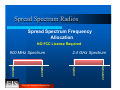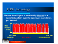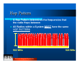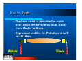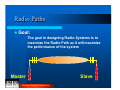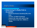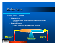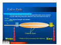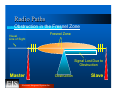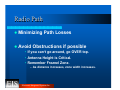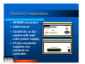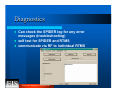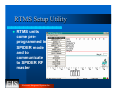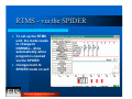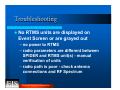
1
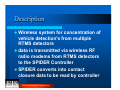
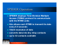
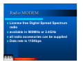
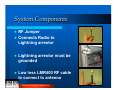
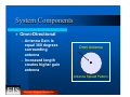
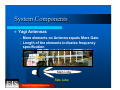
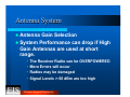
SPIDER
Simple Presence In-lane Detection
Event Reporting
Course Outline
z
z
z
z
z
z
Overview of SPIDER
Radio Operation
System Design
Installation
Software Utility
Troubleshooting
Electronic Integrated Systems Inc.
Overview
Description
z Wireless
system for concentration of
vehicle detection's from multiple
RTMS detectors
z data is transmitted via wireless RF
radio modems from RTMS detectors
to the SPIDER Controller
z SPIDER converts into contact
closure data to be read by controller
Electronic Integrated Systems Inc.
Components of System
z
z
z
SPIDER has an on board master radio
modem (900Mhz or 2.4Ghz) for
communication
Omni antenna, surge suppressor, RF
cable and wall cube power supply are
supplied
1 to 8 RTMS units with built in radio
modems can be connected
Electronic Integrated Systems Inc.
SPIDER Operation
z
z
z
z
z
SPIDER employs Time Division Multiple
Access (TDMA) protocol to communicate
with the RTMS units
this allows each RTMS to transmit its data
every 0.5 seconds
10mS resolution of data
converts data into dry relay contacts
up to 32 contacts available
Electronic Integrated Systems Inc.
Radio Operation
Radio MODEM
z License
free Digital Spread Spectrum
radio
z available in 900MHz or 2.4GHz
z all radio accessories can be supplied
z Data rate is 115Kbps
Electronic Integrated Systems Inc.
Spread Spectrum Radios
Spread Spectrum Frequency
Allocation
NO FCC License Required
Electronic Integrated Systems Inc.
2.4835 GHz
2.4 GHz Spectrum
2.4 GHz
928 MHz
902 MHz
900 MHz Spectrum
FHSS Technology
Narrow Band Signal is continually Hopped in a
specified pattern over the spectrum many times
per second.
Max
Power
1 Watt
902 MHz
ROBUST
RELIABLE
Electronic Integrated Systems Inc.
928 MHz
LICENSE FREE
Hop Pattern
z
z
A Hop Pattern determines the frequencies that
the radio Hops between
All Radios within a System MUST have the same
HOP PATTERN
902 MHz
Electronic Integrated Systems Inc.
928 MHz
Wireless Fundamentals
MULTI-PATH FADING
• Variation in signal level as a result of multipath or obstacles in the RF signal path
results in a condition known as fade.
• High speed data communication is
specially susceptible to failure caused by
fade conditions.
Electronic Integrated Systems Inc.
Wireless Fundamentals
z FADE
MARGIN
– is the difference between received
signal strength and the minimum radio
sensitivity.
– is a major factor that needs to be
considered during initial system
design.
– Relation between Communication
Reliability and Fade Margin
Electronic Integrated Systems Inc.
Radio Path
– The term used to describe the route
over which the RF Energy must travel
from Master to Slave.
– Expressed in dBm. Ie. Path from A to B
is –95 dBm
Master
Electronic Integrated Systems Inc.
Slave
Radio Paths
z Goal:
• The goal in designing Radio Systems is to
maximize the Radio Path as it will maximize
the performance of the system
Master
Electronic Integrated Systems Inc.
Slave
Radio Paths
z Determining
if a Radio Path is
Acceptable
• Examine the Receive Sensitivity (RS) of the
Radio
• Consider a 20 dBm Fade Margin
• Compare this value with value for Path
• Typical Values range from –60dBm to –
110dBm
Electronic Integrated Systems Inc.
Radio Paths
Radio Path Losses
– Obstructions
• Buildings, Hills, Solid Structures, Vegetation (dense
foliage)
– Due to Distance
• Signal dispersion weakens it over distance
Master
Electronic Integrated Systems Inc.
Obstruction
Slave
Radio Path
z
The area around the visual line-of-sight that radio waves spread
out into after they leave the antenna. This area must be clear or
Visual else signal strength will weaken.
Line of Sight
Fresnel Zone
Master
**Width of Zone increases with distance
Electronic Integrated Systems Inc.
Slave
Radio Paths
Obstruction in the Fresnel Zone
Visual
Line of Sight
Fresnel Zone
Signal Lost Due to
Obstruction
Master
Electronic Integrated Systems Inc.
Obstruction
Slave
Radio Path
z Minimizing
z Avoid
Path Losses
Obstructions if possible
• If you can’t go around, go OVER top.
• Antenna Height is Critical.
• Remember Freznel Zone.
– As distance increases, zone width increases.
Electronic Integrated Systems Inc.
System Components
z
z
z
z
SPIDER Controller
shelf mount
12-24V AC or DC comes with wall
cube power supply
37 pin connector
supplies dry
contacts to
controller
Electronic Integrated Systems Inc.
Spider
Setup
RTMS
Tx Rx Pwr
1
2
3
4
5
Antenna
6
7
8
32 CONTACTS
PWR
System Components
z
z
RF Jumper
Connects Radio to
Lightning arrestor
z
Lightning arrestor must be
grounded
z
Low loss LMR400 RF cable
to connect to antenna
Electronic Integrated Systems Inc.
System Components
z
Omni-Directional
– Antenna Gain is
equal 360 degrees
surrounding
antenna
– Increased length
creates higher gain
antenna
Omni Antenna
Antenna Spread Pattern
Electronic Integrated Systems Inc.
System Components
z
Yagi Antennas
– More elements on Antenna equals More Gain.
– Length of the elements indicates frequency
specification
Main Lobe
Side Lobe
Electronic Integrated Systems Inc.
Antenna System
z Antenna
Gain Selection
z System Performance can drop if High
Gain Antennas are used at short
range.
•
•
•
•
The Receiver Radio can be OVERPOWERED
More Errors will occur
Radios may be damaged
Signal Levels >-50 dBm are too high
Electronic Integrated Systems Inc.
Antenna System
z The
SPIDER system uses low gain
omni antennas as the system design
is based on short distances with line
of sight
z an Omni antenna is mounted at 30’ at
SPIDER location, small whip
antennas are mounted on RTMS
units
Electronic Integrated Systems Inc.
Antenna System
z Antenna
Height
– should be mounted as high as possible
– Height becomes more important as the
distances between sites increase
– Remember that the higher the Antenna
is mounted, the more RF Cable is
needed. (adds loss to system)
Electronic Integrated Systems Inc.
System Design
SPIDER Connection
Master
Dipole
Antenna
Spider
FRONT
Tx Rx Pwr
Setup
RTMS
1
2
3
4
5
6
7
8
32 CONTACTS
BACK
Antenna
PWR
110 V AC
INPUT
COMMON
RTMS Input
12 - 24 V AC DC
10
9
8
7
6
5
4
3
2
1
RTMS RS-232
Set Up Port
Small Cabinets at
base of each pole
Contact Pair wiring
to Controller Input.
(10 outputs only shown)
Please refer to Spider User Manual
for wiring and set up allocations
Electronic Integrated Systems Inc.
RTMS Input
12 - 24 V AC DC
RTMS RS-232
Set Up Port
Small Cabinets at
base of each pole
SPIDER System Parameters
z The
SPIDER is set as a “Plug and
Play” system by the factory.
z It is important to have the following
parameters properly assigned to the
radios in the system:
– network address
– hopping pattern
– encryption key
Electronic Integrated Systems Inc.
SPIDER System Parameters
z Network
Address:
– This parameter must be the same in the
SPIDER Controller Master and ALL
RTMS slaves and repeaters. Multiple
networks with different network
addresses may co-exist in a
geographical area without interfering
with each other. Range 0 - 65535.
Electronic Integrated Systems Inc.
SPIDER System Parameters
z Primary
Hopping Pattern:
– This parameter identifies the frequency
hopping pattern between the slaves and
a master. There are 64 patterns (0-63) of
which patterns 0-61 are
preprogrammed.
Electronic Integrated Systems Inc.
SPIDER System Parameters
z Encryption
Key:
– This parameter provides network
security. The Master, slaves and
repeaters must have the same
encryption key to communicate and will
be allocated a range 0 - 65535.
Electronic Integrated Systems Inc.
SPIDER parameters
z Unit
Address:
– Each member of the network is
identified by a unique Unit Address
number.
– The master is designated Unit #0
– the slaves will be Units #1 to #8
(maximum number of RTMS units per
SPIDER is 8)
Electronic Integrated Systems Inc.
Installation
Site Considerations
Antenna Mounting
z
Is there an Antenna Mast
near the cabinet?
– Signal Pole
– Luminaire
– Additional Antenna
Mast
Electronic Integrated Systems Inc.
SPIDER Master Antenna
Antenna
Antenna
Cable
The
The master
master dipole
dipole antenna
antenna must
must
be
be positioned
positioned within
within line
line of
of site
site
of
of the
the slave
slave RTMS
RTMS -- DSS
DSS sensors
sensors
and
and at
at the
the highest
highest point
point possible
possible
SPIDER
Control
Cabinet
Spider
Spider Controller
Controller requires
requires 12
12 -- 24
24 AC
AC or
or DC
DC
Antenna
Antenna Surge
Surge Protector
Protector Grounding
Grounding cable
cable in
in cabinet
cabinet
Electronic Integrated Systems Inc.
RTMS Locations
z RTMS
units should be mounted as
per product specifications
z antenna selection will be based upon
proximity to SPIDER and line-of-sight
Electronic Integrated Systems Inc.
Software Utility
Events Screen
– On opening the SPIDER utility, allow 10
seconds for software to read the controller
Electronic Integrated Systems Inc.
The Events Window
Active RTMS units are
listed showing individual
serial numbers
Zones programmed into
RTMS are displayed currently are shown as
Yellow boxes with XX
until pin assignment is
given
This
This is
is the
the SPIDER
SPIDER main
main window.
window. ItIt provides
provides visual
visual
verification
verification on
on the
the operation
operation of
of an
an active
active system
system
Electronic Integrated Systems Inc.
Pins Selection
z
z
z
click on the yellow zone box to display the
selection screen
The dry relay contacts for each lane of
each detector can be programmed
a total of 32 contacts can be provided
Electronic Integrated Systems Inc.
The Events Window
LINK
LINK shows
shows
synchronization
synchronization level
level
between
between the
the SPIDER
SPIDER
and
and RTMS
RTMS unit.
unit.
A
A reading
reading of
of 10
10 is
is
perfect,
perfect, aa steady
steady
reading
reading of
of 66 or
or less
less
would
would require
require
investigation
investigation
Vehicle targets are shown in red - only after Pin
Assignment is completed and loaded to the SPIDER
Electronic Integrated Systems Inc.
DSS Setup
– Parameters are pre-programmed for system
but can be changed by the user
Electronic Integrated Systems Inc.
DSS Setup
z When
in the DSS Setup screen the Tx
lamp will disappear from the front
panel of the SPIDER as you are no
longer communicating with the
RTMS units.
z If in the DSS Setup for 5 minutes or
longer the SPIDER will automatically
return to normal operation
Electronic Integrated Systems Inc.
DSS Setup - Advanced Setup
Maximum number of
RTMS units in system
# of message retries
if comm failed
Electronic Integrated Systems Inc.
Spectrum
– The spectrum can be analyzed to verify the
best hopping pattern
Electronic Integrated Systems Inc.
Tools
– If an RTMS is left in normal mode, and still has
the same RF parameters, the SPIDER can send
a message to put in the SPIDER mode
Electronic Integrated Systems Inc.
Diagnostics
z
z
z
Can check the SPIDER log for any error
messages (troubleshooting)
self test for SPIDER and RTMS
communicate via RF to individual RTMS
Electronic Integrated Systems Inc.
RTMS Setup Utility
z
RTMS units
come preprogrammed in
SPIDER mode
and to
communicate
to SPIDER RF
master
Electronic Integrated Systems Inc.
RTMS - via the SPIDER
z
To set up the RTMS
unit, the mode needs
to change to
NORMAL - done
automatically when
program is opened
via the SPIDER
z changes back to
SPIDER mode on exit
Electronic Integrated Systems Inc.
Troubleshooting
Troubleshooting
z No
RTMS units are displayed on
Event Screen or are grayed out
– no power to RTMS
– radio parameters are different between
SPIDER and RTMS unit(s) - manual
verification of units
– radio path is poor - check antenna
connections and RF Spectrum
Electronic Integrated Systems Inc.
Troubleshooting
z Link
number is low - constantly
below 6
– indicates multiple message repeats
– radio path is poor - check antenna
connections and height - obstacles in
antenna path
– radio power is too low - increase
Electronic Integrated Systems Inc.
Troubleshooting
z SPIDER
Log file has messages
– messages are created from
communication errors
– if refers to specific RTMS reestablishing contact - may be poor
power at RTMS or poor radio path to
that RTMS
Electronic Integrated Systems Inc.
Troubleshooting
z Further
troubleshooting assistance
is available in the SPIDER User
Manual
Electronic Integrated Systems Inc.