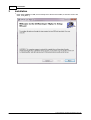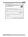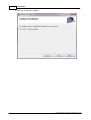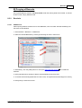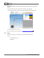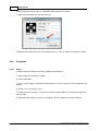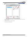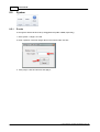
1
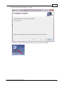
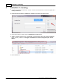
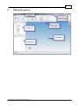
3DROCK+
3DROCK+
User Manual
© 2014 Advance Contech (Singapore) Pte. Ltd.
3DROCK+
User Manual
by Advance Contech (Singapore) Pte. Ltd.
Contents
3
Table of Contents
Part I About
6
Part II System Requirements
9
Part III Installation
12
Part IV Activation / Licensing
18
Part V GUI quick glance
21
Part VI General Workflow
23
Part VII Common Tasks
26
1 Change
...................................................................................................................................
View Mode
26
2 To...................................................................................................................................
make DEM profile distintive
28
3 Pan
...................................................................................................................................
/ Zoom / Rotate view
29
4 Select
...................................................................................................................................
/ De-select Entity
31
5 Show/Hide
...................................................................................................................................
by Selection
34
6 Show/Hide
...................................................................................................................................
by Type
36
7 Rename
...................................................................................................................................
Entity
37
8 Delete
...................................................................................................................................
Entity
38
Part VIII Commands
42
1 Modeling
................................................................................................................................... 42
Point / Line
......................................................................................................................................................... 42
Import PointSet
.................................................................................................................................................. 42
Import Polyline
.................................................................................................................................................. 45
DEM
......................................................................................................................................................... 48
Import VegGis
.................................................................................................................................................. 48
Create Base
.................................................................................................................................................. 49
From PointSet
.................................................................................................................................................. 50
Cut DEM .................................................................................................................................................. 52
Create DOM
..................................................................................................................................................
(Overlay)
54
Apply DOM
.................................................................................................................................................. 58
Pin
......................................................................................................................................................... 59
Create Pin.................................................................................................................................................. 59
Create Overlay
.................................................................................................................................................. 60
ContourSet
......................................................................................................................................................... 60
Create ContourSet
.................................................................................................................................................. 60
Export ContourSet
..................................................................................................................................................
to DXF file
63
SectionSet......................................................................................................................................................... 65
Create SectionSet
.................................................................................................................................................. 65
© 2014 Advance Contech (Singapore) Pte. Ltd.
4
User Manual
RockMass......................................................................................................................................................... 67
Create
.................................................................................................................................................. 67
From PolylineSet
.................................................................................................................................................. 68
From GoCAD
.................................................................................................................................................. 69
Tunnel ......................................................................................................................................................... 71
Create
.................................................................................................................................................. 71
Import
.................................................................................................................................................. 72
Cavern ......................................................................................................................................................... 73
Create
.................................................................................................................................................. 73
2 Computation
................................................................................................................................... 75
Analysis ......................................................................................................................................................... 75
DEM Profile.................................................................................................................................................. 75
Measure ......................................................................................................................................................... 76
Distance &..................................................................................................................................................
Volume
77
Cut & Fill .................................................................................................................................................. 79
Proximity Analysis
.................................................................................................................................................. 80
Boolean ......................................................................................................................................................... 81
3D Boolean
.................................................................................................................................................. 81
3 Borehole
................................................................................................................................... 83
Im port
......................................................................................................................................................... 83
Import
.................................................................................................................................................. 83
Borehole ......................................................................................................................................................... 85
Add/Remove
.................................................................................................................................................. 85
Show Legend
.................................................................................................................................................. 86
Graph
......................................................................................................................................................... 86
Value-Depth
.................................................................................................................................................. 87
Histogram.................................................................................................................................................. 89
Filtering records
......................................................................................................................................................... 90
Change display
.........................................................................................................................................................
type
93
4 Visualize
................................................................................................................................... 95
Navigation......................................................................................................................................................... 95
FlyThrough.................................................................................................................................................. 95
Sim ulation......................................................................................................................................................... 96
Stages .................................................................................................................................................. 96
5 System
................................................................................................................................... 98
Z scale
Reset
About
......................................................................................................................................................... 98
......................................................................................................................................................... 99
......................................................................................................................................................... 99
Part IX Support & Contact
101
© 2014 Advance Contech (Singapore) Pte. Ltd.
Part
I
6
1
About
About
3D Rock Plus (3DROCK+) is a general purpose three dimensional (3D) Geographical Information
System (GIS) developed by Advance Contech (Singpaore) Pte. Ltd. for the joint-research project
Underground Technology & Rock and Engineering (UTRE) Phase II of Nanyang Technological
University (NTU) and Defence Science Technology Agency (DSTA) Singapore.
This user manual provides information on the operation of 3DROCK+.
Last updated: 2nd April 2014, Singapore
© 2014 Advance Contech (Singapore) Pte. Ltd.
7
© 2014 Advance Contech (Singapore) Pte. Ltd.
Part
II
9
2
System Requirements
Basic System Requirements
Intel i5 CPU @ 2.5G Hz (or better)
4 GB DDR3 RAM (or more)
7200 rpm harddisk with 250GB capacity (or higher) [Solid State Drive recommended)
ATI Radeon HD (or NVIDIA Quadro) series graphics card with dedicated 2GB VRAM
1024 x 768 resolution with 32-bit color depth (or better)
Keyboard and 3-button mouse with scroll-wheel
32-bit or 64-bit Windows Vista/7/8 operating system with .Net Framework 3.5 SP1 preinstalled
Note: 64-bit operating system recommended.
© 2014 Advance Contech (Singapore) Pte. Ltd.
10
System Requirements
© 2014 Advance Contech (Singapore) Pte. Ltd.
Part
III
12
3
Installation
Installation
1. Insert Setup CDROM / USB, and run Setup.exe to launch the installer, a welcome screen will
show, click [Next >]
© 2014 Advance Contech (Singapore) Pte. Ltd.
13
2. Change the default installation path (if necessary), decide if the program will be installed for all
user of the computer, click [Next >]
© 2014 Advance Contech (Singapore) Pte. Ltd.
14
Installation
3. Click Next to start the installation
© 2014 Advance Contech (Singapore) Pte. Ltd.
15
4. Click [Close] after the installation is finished.
5. A new icon is added to the Desktop, double click on that to launch the program.
© 2014 Advance Contech (Singapore) Pte. Ltd.
16
Installation
© 2014 Advance Contech (Singapore) Pte. Ltd.
Part
IV
18
4
Activation / Licensing
Activation / Licensing
1. To prevent unauthorized execution, 3D Rock needs to be activated on each new computer that it
is being installed on.
2. Upon first execution after the installation, a dialog box will show the Locking Code.
3. Copy and email the Locking Code to [email protected].
4. Advance Contech will send you a .license file. Copy the .license file to the program installation
folder, typically located in "C:\Program Files\Advance Contech (Singapore) Pte Ltd\3D
Rock\".
5. Restart 3DROCK+.
© 2014 Advance Contech (Singapore) Pte. Ltd.
19
© 2014 Advance Contech (Singapore) Pte. Ltd.
Part
V
21
5
GUI quick glance
© 2014 Advance Contech (Singapore) Pte. Ltd.
Part
VI
23
6
General Workflow
1.
Import PointSet from DXF file
2.
Create DEM from PointSet
3.
Create ContourSet (horizontal contour lines) from DEM
4.
Export ContourSet to DXF file
63.
5.
Apply DOM to improve visuals
54.
6.
Create SectionSet (i.e. Fence Diagram).
7.
Create Rock Mass using two DEMs
8.
Create Tunne
and Cavern
73 .
9.
Measure the area and volume
77
10.
Combine Tunnel and Cavern
11.
Import
12.
Extract
13.
Define construction stages
83
71l
and add
90
85
42 .
50,
or import from VEGGIS DEM
67
48.
60 .
65
or by using Polylines
68 .
of DEM, Rock Mass, Tunnel and Cavern.
81.
borehole from AGS(SG) data sets.
and plot graph
© 2014 Advance Contech (Singapore) Pte. Ltd.
86
against selected borehole data.
96
and perform real-time walk through
95.
24
General Workflow
© 2014 Advance Contech (Singapore) Pte. Ltd.
Part
VII
26
7
Common Tasks
Common Tasks
Abbreviation used in the following chapters.
[LMB] = Left Mouse Button
[MMB] = Middle Mouse Button
[RMB] = Right Mouse Button
7.1
Change View Mode
Click Home > Display > Wireframe | Shaded | Rendered select how the model is displayed in the
Work Space.
Wireframe Mode
© 2014 Advance Contech (Singapore) Pte. Ltd.
Change View Mode
Shaded Mode
Rendered Mode
© 2014 Advance Contech (Singapore) Pte. Ltd.
27
28
7.2
Common Tasks
To make DEM profile distintive
To exaggerate the DEM profile, user may enter a larger Z scale using the System > Height > Z scale
98 command.
© 2014 Advance Contech (Singapore) Pte. Ltd.
To make DEM profile distintive
7.3
Pan / Zoom / Rotate view
Pan
Press and hold middle mouse button while dragging
Dynamic Zoom
Scroll [MMB] while cursor is within the Work Space
Zoom Extend
Click the [Zoom Extend] icon at the upper right corner of the Work Space
Rotate
Click and hold [RMB] while dragging in Work Space.
Rotate to specific view plane
by either
a] clicking the [Top], [Front], [Side], [Iso] buttons.
© 2014 Advance Contech (Singapore) Pte. Ltd.
29
30
Common Tasks
b] clicking the faces of the view cube.
© 2014 Advance Contech (Singapore) Pte. Ltd.
Pan / Zoom / Rotate view
7.4
Select / De-select Entity
Select Entity
clicking at the Entity Name in the Entity List
© 2014 Advance Contech (Singapore) Pte. Ltd.
31
32
Common Tasks
clicking Home > Mode > Select, click hold [LMB] to enclose all the entities to be selected in the
Work Space
© 2014 Advance Contech (Singapore) Pte. Ltd.
Select / De-select Entity
De-select Entity
Click Home > Mode > Clear
© 2014 Advance Contech (Singapore) Pte. Ltd.
33
34
7.5
Common Tasks
Show/Hide by Selection
To Hide
Select the entity, click Home > Hide/Show > Hide Selected.
© 2014 Advance Contech (Singapore) Pte. Ltd.
Show/Hide by Selection
To Show
Click Home > Hide/Show > Show All.
© 2014 Advance Contech (Singapore) Pte. Ltd.
35
36
7.6
Common Tasks
Show/Hide by Type
1. Click Home > Hide/Show Quick Access Icon.
2. Check / Un-check the desired type of object to hide/show.
3. Click [Apply].
4. Click [Done] to close tool box.
© 2014 Advance Contech (Singapore) Pte. Ltd.
Show/Hide by Type
7.7
Rename Entity
Click Entity Name in Entity List, type the new name in Property field, and hit [Enter].
Note : Name cannot contain space character.
© 2014 Advance Contech (Singapore) Pte. Ltd.
37
38
7.8
Common Tasks
Delete Entity
1. Select Entity, click Home > Edit > Delete.
© 2014 Advance Contech (Singapore) Pte. Ltd.
Delete Entity
2. Click [Yes] to delete the selected Entity
© 2014 Advance Contech (Singapore) Pte. Ltd.
39
40
Common Tasks
© 2014 Advance Contech (Singapore) Pte. Ltd.
Part
VIII
42
Commands
8
Commands
8.1
Modeling
8.1.1
Point / Line
Enter topic text here.
8.1.1.1
Import PointSet
1. Click Modeling > Point / Line > Import PointSet
2.
© 2014 Advance Contech (Singapore) Pte. Ltd.
Modeling
3. Click [Open DXF]
4. Select the DXF file, click [Open]
© 2014 Advance Contech (Singapore) Pte. Ltd.
43
44
Commands
5. Check (Select) the layers containing height points to be imported, click [Import Height Points from
Selected Layer(s)].
© 2014 Advance Contech (Singapore) Pte. Ltd.
Modeling
45
6. New height points are all imported and grouped under a new collection under "PointSet" header,
click [Zooom Extend] icon to adjust the Work Space to display them
8.1.1.2
Import Polyline
1. Click Modeling > Point / Line > Import Polyline
© 2014 Advance Contech (Singapore) Pte. Ltd.
46
Commands
2. Click [Open DXF]
3. Select the DXF file, click [Open]
© 2014 Advance Contech (Singapore) Pte. Ltd.
Modeling
47
4. Check (Select) the layers containing the features to be imported, click [Import Polylines from
Selected Layer(s)].
5. New feature polylines are all imported and grouped under a new collection under "PolylineSet"
header, click [Zooom Extend] icon to adjust the Work Space to display them
© 2014 Advance Contech (Singapore) Pte. Ltd.
48
Commands
8.1.2
DEM
8.1.2.1
Import VegGis
Use this tool to import an existing DEM layer from VegGis system.
Note: VegGis *.dem file format is incompatible with other GIS standard file format, hence this doesn't
work on other *.dem files created by other GIS software.
1. Click Modeling > DEM > Import VegGis.
2. Select the VEGGIS DEM file, and click [Open].
© 2014 Advance Contech (Singapore) Pte. Ltd.
Modeling
3. The imported DEM is added to the Entity List and displayed in Work Space.
8.1.2.2
Create Base
Use this tool to create a planar DEM, typically as the top (or bottom) most bounding layer
1. Click Modeling > DEM > Create Base.
2. System will automatically calculate the current extent and centroid of the Scene. Adjust the
values as necessary.
© 2014 Advance Contech (Singapore) Pte. Ltd.
49
50
Commands
3. Click [Create]. A new DEM will be added to the Scene.
8.1.2.3
From PointSet
1. Select the PointSet
2. Click Modeling > DEM > From PointSet
© 2014 Advance Contech (Singapore) Pte. Ltd.
Modeling
3. Choose the type of triangulation methods, click [Apply]
© 2014 Advance Contech (Singapore) Pte. Ltd.
51
52
Commands
4. The created DEM is listed in Entity List and displayed in the Work Space.
8.1.2.4
Cut DEM
Trim and extract a smaller portion out from a larger DEM.
1. Import a PolylineSet 42 containing the boundary of the smaller DEM. The PolylineSet shall
contain only ONE polyline, of which the last vertex needs not be meeting its first vertex (i.e. an open
polyline in DXF is acceptable).
2. Click Modeling > DEM > Cut DEM.
© 2014 Advance Contech (Singapore) Pte. Ltd.
Modeling
53
3. Select the DEM (to be cut) and the PolylineSet (as the boundary) from the drop down boxes.
Click [Cut].
4. A new DEM will be created.
Note: This could be a time consuming process with complex DEM processed by using a low-end
computer system.
© 2014 Advance Contech (Singapore) Pte. Ltd.
54
8.1.2.5
Commands
Create DOM (Overlay)
1. Create at least two Pins
59
pointing at two locations of the desired DEM.
2. Click Modeling > Pin > Create Overlay
© 2014 Advance Contech (Singapore) Pte. Ltd.
Modeling
3. Select the DEM to be overlaid from the drop down list.
4. Click [Open overlay image] and select the image file.
© 2014 Advance Contech (Singapore) Pte. Ltd.
55
56
Commands
5. Select the first and second pin to be used as M1 and M2 markers, respectively, from the drop
down list.
5. Click [Place M1], and click at the corresponding location on the image.
© 2014 Advance Contech (Singapore) Pte. Ltd.
Modeling
6. Click [Place M2], and click at the corresponding location on the image.
7. Click [Create and Save] to save the resultant DOM as bitmap file.
© 2014 Advance Contech (Singapore) Pte. Ltd.
57
58
8.1.2.6
Commands
Apply DOM
1. Click Modeling > DEM > Apply Overlay.
2. Click [Load].
3. Choose the desired BMP image file, click [Open].
4. Select the DOM from the list.
5. Select the DEM in scene, and click [Apply].
© 2014 Advance Contech (Singapore) Pte. Ltd.
Modeling
6. Click [Done] to close the tool box.
Note: DOM is only visible when the Display Mode is set to "Rendered'
8.1.3
Pin
8.1.3.1
Create Pin
1. Click Modeling > Pin > Add Pin.
2. Click [Track], and click at the desired location in the Scene.
3. Confirm the X and Y values, click [Add] to create a new Pin.
4. Click [Close] to close the tool box.
© 2014 Advance Contech (Singapore) Pte. Ltd.
26.
59
60
Commands
8.1.3.2
Create Overlay
See DEM:Create DOM (Overlay)
8.1.4
ContourSet
8.1.4.1
Create ContourSet
54
1. Select the DEM
2. Click Modeling > Contour > Create
© 2014 Advance Contech (Singapore) Pte. Ltd.
Modeling
61
3. Enter the Starting, Ending and Interval of contour line height and click [Auto Generate] to populate
the Heights (in meter) List, and click [Create ContourSet].
© 2014 Advance Contech (Singapore) Pte. Ltd.
62
Commands
4. The new ContourSet is added to the Entity List and displayed in Work Space.
© 2014 Advance Contech (Singapore) Pte. Ltd.
Modeling
8.1.4.2
Export ContourSet to DXF file
1. Select the ContourSet(s) to be exported
2. Click Modeling > Contour > Export to
© 2014 Advance Contech (Singapore) Pte. Ltd.
63
64
Commands
3. Click [Export ...], specify the file name, and click [Save], click [Close] to close the export dialog.
© 2014 Advance Contech (Singapore) Pte. Ltd.
Modeling
8.1.5
SectionSet
8.1.5.1
Create SectionSet
1. Click Modeling > SectionSet > Create
© 2014 Advance Contech (Singapore) Pte. Ltd.
65
66
Commands
2. Select each DEM from "Available DEM" list and click [>] to add relevant DEMs (from top most to
the bottom most) into the Selected DEM list.
3. Click [Track] button and click at the lower left corner of the SectionSet and click to grab the X,Y
coordinates into "Origin" input box.
© 2014 Advance Contech (Singapore) Pte. Ltd.
Modeling
67
4. Enter number of repetition and spacing between each Section and click [Create SectionSet].
5. New SectionSets will be added. Click [Done] to close the tool box.
8.1.6
RockMass
8.1.6.1
Create
1. Click Modeling > Rock Mass > Create.
© 2014 Advance Contech (Singapore) Pte. Ltd.
68
Commands
2. Select the top and bottom bounding DEM from the drop down box, and click [Create].
3. Click [Done] to close the tool box.
8.1.6.2
From PolylineSet
3DROCK+ can create new Rock Mass by inferring a solid based on series of closed polylines
bounding the shape of the Rock Mass. The quality and end result depends on the resolutions and
conformity of the polylines' vertexes.
All the polylines of the same rock mass must be imported from DXF file in a single batch (i.e. stored
under one PolylineSet).
1. Import the PolylineSet
45
of which all the polylines bounding the Rock Mass is included.
2. Click Modeling > RockMass > From PolylineSet.
3. Select the PolylineSet from the drop down list, and click [Create].
© 2014 Advance Contech (Singapore) Pte. Ltd.
Modeling
4. A new Rock Mass will be added to the Scene.
8.1.6.3
From GoCAD
3DROCK+ can import GoCAD object saved as 3DPolyFace type via DXF file.
1. Click Modeling > Rock Mass > From GoCAD.
2. Click [Open DXF], select and open the DXF file containing GoCAD 3D object.
© 2014 Advance Contech (Singapore) Pte. Ltd.
69
70
Commands
3. Click at the layer that contains the 3D object. Click [Import 3D body from Selected Layer(s)].
4. A new Rock Mass will be added to the Scene.
Note: Importing 3D object from GoCAD is an computational intensive process.
© 2014 Advance Contech (Singapore) Pte. Ltd.
Modeling
8.1.7
Tunnel
8.1.7.1
Create
71
User can create new Tunnel by "sweeping" a cross section (as a closed polyline) along a build path.
Both the cross seciton and build path have to be imported as PolylineSet
45
.
1. Select Modeling > Tunnel > Create
2. Select the PolylineSet for both Cross section and Build path.
3. If, necessary, tick the check box and specify the number of stages the new Tunnel should be
built.
4. Click [Create]. A new Tunnel (with multiple segments, if specified) will be added to the Scene.
© 2014 Advance Contech (Singapore) Pte. Ltd.
72
Commands
5. Click [Done] to close the tool box.
8.1.7.2
Import
User can also import 3D tunnel object from 3rd-party software like AutoDesk Inventory using binary
*.STL file.
1. Click Modeling > Tunnel > Import.
2. Select the .STL file and click [Open].
3. A new Tunnel object will be added to Scene.
© 2014 Advance Contech (Singapore) Pte. Ltd.
Modeling
8.1.8
Cavern
8.1.8.1
Create
73
User can create new Cavern by "sweeping" a cross section (as a closed polyline) along a build path.
Both the cross section and build path have to be imported as PolylineSet
45
.
1. Click Modeling > Cavern > Create.
2. Select the PolylinSet for both the Cross section and the Build path from the drop down list.
3. Tick and specify the number of stages a new cavern shall be built, if necessary.
© 2014 Advance Contech (Singapore) Pte. Ltd.
74
Commands
4. Click [Create]. A new Cavern object will be added to the Scene.
5. Click [Done] to close the tool box.
© 2014 Advance Contech (Singapore) Pte. Ltd.
Modeling
8.2
Computation
8.2.1
Analysis
8.2.1.1
DEM Profile
75
1. Click Computation > Analysis > DEM Profile
2. Select the DEM layer of which the profile is to be calculated.
3. Select the PolylineSet which defines the cutting path.
4. Enter the resolution (interval between sampling points) in meter.
5. Tick "add as new PolylineSet" should a new polyline is to be added along the profile cutting path.
6. Click [Create & View] to display the DEM profile.
© 2014 Advance Contech (Singapore) Pte. Ltd.
76
Commands
7. A new PolylineSet will be added to the Scene if Step 5 is done.
8. Click [Done] to close.
8.2.2
Measure
© 2014 Advance Contech (Singapore) Pte. Ltd.
Computation
8.2.2.1
Distance & Volume
User can measure the
a) distance between two objects (any 2D or 3D objects),
b) surface area of DEM (i.e. 2D surface object), and
c) total volume of Rock Mass, Tunnel and Cavern (i.e. 3D objects).
Distance
1. Click Computation > Measure > Distance & Volume
2. Select two objects
31
from the Scene.
3. Click [Get C/C Distance]. The centroid-to-centroid distance of the selected objects will be
displayed.
Surface Area
1. Click Computation > Measure > Distance & Volume
2. Select a DEM
31.
© 2014 Advance Contech (Singapore) Pte. Ltd.
77
78
Commands
3. Click [Get Surface Area]. The total surface area of the selected DEM will be displayed.
Volume
1. Click Computation > Measure > Distance & Volume
2. Select a Rock Mass, Tunnel OR Cavern
3. Click [Get Mass Volume]. The total volume of the selected 3D object will be displayed.
© 2014 Advance Contech (Singapore) Pte. Ltd.
Computation
8.2.2.2
79
Cut & Fill
1. Select Computation > Measure > Cut & Fill.
2. Select the desired DEM from the drop down list.
3. Select the type of measurement needed, i.e. Cut or Fill.
4. Specify the reference datum level. User may use the maximum and minimum of the selected
DEM as a guide.
5. Click [Get Volume]. The total Cut (or Fill) volume will be displayed.
© 2014 Advance Contech (Singapore) Pte. Ltd.
80
Commands
6. Click [Done] to close the tool box.
8.2.2.3
Proximity Analysis
User may get a list of PolylineSet, Rock Mass, Tunnel and/or Cavern contained within another buffer
object made of 3D entity (i.e. Rock Mass, Tunnel or Cavern).
1. Click Computation > Measurement > Proximity Analysis.
2. Select the buffer object from the drop down list.
3. Tick "include partially bounded" to instruct program detect object that are also partially contained
within the buffer object.
4. Click [Query], and all the detected objects will be listed in the Result list box.
© 2014 Advance Contech (Singapore) Pte. Ltd.
Computation
5. Click [Select all resultants in view] to select all the entity in the Work Space.
Note: This is a time consuming calculation for large buffer object of Scene with many entities.
8.2.3
Boolean
8.2.3.1
3D Boolean
1. Click Computation > Boolean > 3D Boolean.
2. Select and 1st and 2nd Object for Boolean operation.
3. Select the type of Boolean operation.
4. Select the type of object to be created.
5. Click [Create]. A new type of object (as selected in Step 4) will be added to the Scene.
© 2014 Advance Contech (Singapore) Pte. Ltd.
81
82
Commands
6. Click [Done & Close] to close the tool box.
Note: The resultant is affected by the order of the 1st and 2nd object as selected in Step 2.
© 2014 Advance Contech (Singapore) Pte. Ltd.
Computation
8.3
Borehole
8.3.1
Import
83
The Borehole data must be imported before it can be visualized, analyzed and plotted in 3DROCK+.
8.3.1.1
Import
1. Click Borehole > Import > Import.
2. Click [. . .], and select the *.MDB file(s). [Hint: To select multiple files in the Open File Dialog,
hold [Ctrl] key and click on the file names].
3. Click [Open], all the selected files are listed in the list box. Click [Connect] to open the database
files.
© 2014 Advance Contech (Singapore) Pte. Ltd.
84
Commands
4. You may select different table from the drop down list to preview the merged records.
5. Click [Merge and Close] to import the tables and records.
Note:
A] Database Engine on Client Machine
3DROCK+ imports and visualizes AGS(SG) Borehole data from Microsoft Access Database (*.MDB)
via
a) Microsoft JET ODBC engine (on 32-bit Windows Operating System), or
b) Microsoft Access version 12 Engine (on 64-bit Windows Operating System).
The underlying data driver/engine has to be pre-installed and configured on the client system before
data import can be performed.
© 2014 Advance Contech (Singapore) Pte. Ltd.
Borehole
85
B] Purging of Records
The imported data are stored in "boreholes.mdb" under the working folder of the model. To remove
all the records, simply delete this file.
8.3.2
Borehole
8.3.2.1
Add/Remove
After Importing borehole records from Access Database, user can select and add borehole(s) into
the Scene for visualization.
1. Click Borehole > Borehole > Add/Remove
2. Select the desired Borehole by checking/unchecking the item in the list box.
3. Alternatively, click the [Filter] button to call up the Select Record tool box
selection.
90
for advanced
4. Click [Add selected to Scene] to add the selected Borehole into the Scene.
5. To remove all the existing Boreholes from the Scene, click [Remove All Borehole(s) from Scene].
6. Click [Done] to close the tool box.
© 2014 Advance Contech (Singapore) Pte. Ltd.
86
8.3.2.2
Commands
Show Legend
Boreholes are visualized in Scene based on either GEOL_GEO, GEOL_GEO2 or GEOL_GEO3
properties.
To show the Legend of the color used for each of the GEOL code as displayed,
1. Click Borehole > Borehole > Show Legend. The legend is displayed as a floating tool box.
2. Click [x] of the Legend box to close it.
Note: The above steps are to be repeated if the borehole display type is changed
8.3.3
93.
Graph
For any kind of property (i.e. AGS(SG) table), two types of graphing are available,
namely
a) Value-Depth Graph, and
b) Histogram
© 2014 Advance Contech (Singapore) Pte. Ltd.
Borehole
8.3.3.1
Value-Depth
1. Click Borehole > Graph > Value-Depth
2. Select the desired records
90.
3. Select the Table from the drop down list.
4. Select the X-Axis and Y-Axis data.
5. Optional: Type the Title, and X- and Y-Axis label of the graph.
© 2014 Advance Contech (Singapore) Pte. Ltd.
87
88
Commands
6. Click [Plot] to display the graph.
7. The displayed graph can be copied to clipboard by clicking [Copy to clipboard] and paste into
compatible 3rd-party software (like MS Excel or MS Word) for reporting purposes.
8. Click [Done] to close the tool box.
© 2014 Advance Contech (Singapore) Pte. Ltd.
Borehole
8.3.3.2
89
Histogram
1. Click Borehole > Graph > Histogram.
2. Select the desired records
90.
3. Select the Table from the drop down list.
4. Select the Value of Interest (i.e. property) from the drop down list.
5. Specify the Intervals in the input table.
6. Tick "Split into different series" if needed.
7. Optional: Input the Title, X- and Y-Axis label.
8. Click [Plot] to display the histogram.
9. The displayed graph can be copied to clipboard by clicking [Copy to clipboard] and paste into
compatible 3rd-party software (like MS Excel or MS Word) for reporting purposes.
© 2014 Advance Contech (Singapore) Pte. Ltd.
90
8.3.4
Commands
Filtering records
1. To select multiple records that match certain common criteria, click the [Filter] button on the
borehole tool box to bring up the Select Record Dialogue.
2. Select the Master Table which the criteria will be built.
3. Key in the criteria for the respective properties. Value type properties are listed on the left input
table, and string type properties are listed on the right.
4. Click [Build Query String] to preview the criteria.
© 2014 Advance Contech (Singapore) Pte. Ltd.
Borehole
91
5. The combine the matching records in addition to those already been selected in the calling tool
box, click [Select (Additive)].
6. Alternatively, to clear the previous selections in the calling tool box before adding the new
matching records, click [Select (Exclusive)].
7. Click [Done] to close the tool box.
© 2014 Advance Contech (Singapore) Pte. Ltd.
92
Commands
Secondary Filter
In the event multi-level criteria selection is needed,
1. Check "Secondary Filter".
2. Select the Secondary Table for which the criteria will be built upon.
3. Select the respective Field of the Secondary Table which the constraint is imposed on.
4. Specify the constraint value/text in the respective input box.
5. Select and match the respective field pair (one for the lower bound, one for the upper bound) which
the limiting range values could be extracted.
6. Select the field from the Master Table for which the the records will be filtered against the limiting
range values.
7. Click [Select (Additive)] or [Select (Exclusive)] to select the records in the calling tool box.
© 2014 Advance Contech (Singapore) Pte. Ltd.
Borehole
8.3.5
Change display type
To change the display type of the borehole (i.e. visualized based on either GEOL_GEO,
GEOL_GEO2, or GEOL_GEO3 code),
1. Click the arrow marker at the lower right corner of the Hide/Show ribbon group.
© 2014 Advance Contech (Singapore) Pte. Ltd.
93
94
Commands
2. Select the type from the drop down list. The visual display of the Borehole in the Scene will be
changed with immediate effect.
Note: Should the Borehole GEOL Legend tool box is being displayed, reopen
information.
86
it to update the
© 2014 Advance Contech (Singapore) Pte. Ltd.
Borehole
8.4
Visualize
8.4.1
Navigation
8.4.1.1
FlyThrough
95
To navigate using First-Person view mode,
1. Click Visualize > Navigation > Fly-Through.
2. Change the resolution of moving step and rotation, as necessary.
3. Ensure the Work Space has the focus (by clicking at it), press and hold W, A, S, D, Q and E to
move/rotate the virtual camera and explore the Scene.
4. Alternatively,
a) scroll the mouse wheel to move forward/backward,
b) press and hold right mouse button while moving the mouse to look around, and
c) press and hold middle mouse button while moving the mouse to pan the virtual camera
5. Click [Done & Close] to exit First-Person view mode, and close the tool box.
Traveling on a designated path
© 2014 Advance Contech (Singapore) Pte. Ltd.
96
Commands
To keep the virtual camera stays on a designated path defined by a polyline,
1. Select the PolylineSet from the drop down list.
2. Make the work space has focus, and navigate using W, S key or middle mouse button scrolling.
8.4.2
Simulation
8.4.2.1
Stages
To create stages to visualize construction/destruction sequences,
1. Click Visualize > Simulation > Stages.
2. Check "Edit Mode".
3. Click [+] at the bottom of Simulation Stages list box. A new <<noname>> entry is added into the
list box.
4. Click the new <<noname>> entry.
5. Change its name to "Stage 1" in the text box under "Stage Details". Click [Update] to apply the
name change.
6. Make the select stage to exclude (i.e. hiding) all entities by default by checking "Hide all".
© 2014 Advance Contech (Singapore) Pte. Ltd.
Visualize
97
7. Select the entity the be excluded (i.e. to be shown) for this stage by selecting them in the Scene
31, and click [+] button below the Except list box.
8. Uncheck "Edit Mode", and click "Stage 1", you will see only the selected entity in Step 7 is being
displayed in the Scene.
9. Repeat Step 3 to Step 7 to create more stages.
10. Click [Done] to close the tool box.
© 2014 Advance Contech (Singapore) Pte. Ltd.
98
Commands
8.5
System
8.5.1
Z scale
To change the vertical visual scale (to exaggerate the profile of DEM, especially),
1. Click System > Height > Z scale.
2. Enter a positive, none-zero integer value in the "New Z scale" text box .
3. Click [OK] to close and tool box and apply it.
© 2014 Advance Contech (Singapore) Pte. Ltd.
System
8.5.2
Reset
To restore back all the dock panels that were closed,
1. Click System > Panel > Reset.
8.5.3
About
Clicking System > Help > About displays 3DROCK+ version and copyright information.
© 2014 Advance Contech (Singapore) Pte. Ltd.
99
Part
IX
101
9
Support & Contact
For technical support, please contact
Advance Contech (Singapore) Pte. Ltd.
Tel
Email
Website
(+65) 6560 6509
[email protected]
http://www.advance-contech.com
Business hour Monday to Friday, 9 am to 5 pm, exclude public holidays
© 2014 Advance Contech (Singapore) Pte. Ltd.