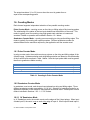
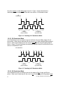
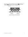
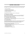
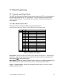
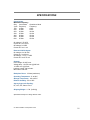
1
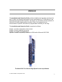
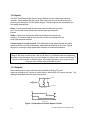
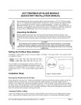
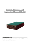
CTI 2502 TWO CHANNEL HIGH SPEED COUNTER INPUT MODULE INSTALLATION AND OPERATION GUIDE Version 1.0 CTI Part # 062-00378-010 062-00378-010 2502IOG $25 Copyright © 2008 Control Technology Inc. All rights reserved. This manual is published by Control Technology Inc., 5734 Middlebrook Pike, Knoxville, TN 37921. This manual contains references to brand and product names which are tradenames, trademarks, and/or registered trademarks of Control Technology Inc. and Siemens AG. Other references to brand and product names are tradenames, trademarks, and/or registered trademarks of their respective holders. DOCUMENT DISCLAIMER STATEMENT Every effort has been made to ensure the accuracy of this document; however, errors do occasionally occur. CTI provides this document on an "as is" basis and assumes no responsibility for direct or consequential damages resulting from the use of this document. This document is provided without express or implied warranty of any kind, including but not limited to the warranties of merchantability or fitness for a particular purpose. This document and the products it references are subject to change without notice. If you have a comment or discover an error, please call us toll-free at 1-800-537-8398. REVISION HISTORY Version 1.0 04/23/08 01/18/11 Original Release Changed ON/OFF voltages for count inputs on specification page CTI 2502 Installation and Operation Guide iii PREFACE This Installation and Operation Guide provides installation and operation instructions for the CTI 2502 Two-Channel High Speed Counter Input Module for CTI 2500 Series™ and Simatic® 505 programmable controllers. We assume you are familiar with the operation of Simatic® 505 series programmable controllers. Refer to the appropriate user documentation for specific information on programmable controller you are using. This Installation and Operation Guide is organized as follows: Chapter 1 provides a description of the module. Chapter 2 covers installation and wiring. Chapter 3 is a guide to troubleshooting. Appendix A details compatibility between the 2502 and the Siemens® 505-7002. The Model 2502 Two-Channel High Speed Counter Input Module CTI 2502 Installation and Operation Guide v vi CTI 2502 Installation and Operation Guide USAGE CONVENTIONS NOTE: Notes alert the user to special features or procedures. CAUTION: Cautions alert the user to procedures that could damage equipment. WARNING: Warnings alert the user to procedures that could damage equipment and endanger the user. CTI 2502 Installation and Operation Guide vii viii CTI 2502 Installation and Operation Guide TABLE OF CONTENTS CHAPTER 1. OVERVIEW........................................................................................ 1 1.0. Product Summary................................................................................................. 1 1.1. Features ................................................................................................................ 1 1.2. Front Panel Description........................................................................................ 2 1.2.1. Active LED 1.2.2. Status LEDs 2 3 1.2. Input/Output Connector ........................................................................................ 3 1.3. Asynchronous Operation ..................................................................................... 3 1.4. Inputs .................................................................................................................... 4 1.5. Outputs ................................................................................................................. 4 1.6. Counting Modes ................................................................................................... 5 1.6.1 Pulse Counter Mode 1.6.2 Quadrature Counter Mode 5 5 CHAPTER 2. INSTALLATION ................................................................................. 9 2.1. Planning the Installation ....................................................................................... 9 2.1.1. Calculating the I/O Base Power Budget 2.1.2. Input Signal Wiring 9 9 2.2. Unpacking the Module ....................................................................................... 10 2.3. Configuring the Module ...................................................................................... 11 2.3.1 Setting the Counter Mode 2.3.2. Setting the Reset Filtering Mode 11 12 2.4. Inserting the Module into the I/O Base .............................................................. 12 2.5. Wiring the I/O Connector ................................................................................... 12 2.6 Adding the Module to the I/O Configuration ....................................................... 13 2.7 Module Programming ......................................................................................... 15 2.7.1 2.7.2 3.1.2 3.1.3 3.1.4 Controller Input/Output Words WX1 Module Status Word WX2, WX3 Current Count Values WY4 Module Setup Word WY5-WY8 Counter Preset Words 15 15 16 16 17 CHAPTER 4. TROUBLESHOOTING ..................................................................... 19 SPECIFICATIONS ................................................................................................. 21 APPENDIX A. COMPATIBILITY WITH SIEMENS 505-7002 ............................. 23 APPENDIX B. JUMPER SETTINGS LOG SHEET ................................................ 25 LIMITED PRODUCT WARRANTY......................................................................... 27 REPAIR POLICY.................................................................................................... 29 CTI 2502 Installation and Operation Guide ix TABLE OF FIGURES Figure 1.1 2502 Front Panel ................................................................................................. 2 Figure 1.2 Status LEDs ........................................................................................................ 3 Figure 1.3 Operation of Counter Output Circuits .................................................................. 4 Table 1.1 Counting in Pulse Counter Mode .......................................................................... 5 Figure 1.4 Counting in 1X Quadrature Mode ....................................................................... 6 Figure 1.5 Counting in 2X Quadrature Mode ....................................................................... 6 Figure 1.6 Counting in 4X Quadrature Mode ....................................................................... 7 Figure 2.1 Configuring Module Jumpers............................................................................ 11 Figure 2.2 2502 I/O Connector Wiring ............................................................................... 13 Figure 2.3 Example I/O Configuration Chart ....................................................................... 14 Table 2.1 Module Status Word .......................................................................................... 15 Table 2.2 Module Setup Word ........................................................................................... 16 Figure 3.1 Troubleshooting Matrix ...................................................................................... 19 CTI 2502 Installation and Operation Guide xi CHAPTER 1. OVERVIEW 1.0. Product Summary The CTI 2502 Two-Channel High Speed Counter Input Module is a member of Control Technology’s family of I/O modules compatible with CTI 2500 Series™ and Simatic® 505 programmable controllers. It is designed to count pulses on the inputs and return the current count and status to the controller. 1.1. Features The 2502 provides two independent high-speed counter channels. Each channel includes the following features. Four counter modes: Pulse counter Quadrature counter modes: 1X, 2X, 4X A 10 kHz count rate with a minimum pulse width of 25 s. Four inputs: two count inputs reset inhibit Two field outputs, each controlled by a separate programmable preset. LED indicators display the status of the A and B count inputs, and of Y1 and Y2 outputs. All inputs may be sinking or sourcing (with external 24 VDC power supply). WARNING: The High Speed Counter Module directly controls its four outputs. Even when the programmable controller switches from the Run mode to the Program mode, the High Speed Counter continues to function and activate its outputs as programmed. This means that if you switch the controller to Program mode, any devices controlled by the four outputs of the High Speed Counter will continue to operate as programmed. CTI 2502 Installation and Operation Guide 1 1.2. Front Panel Description Active LED Status LEDs I/O Connections Figure 1.1 2502 Front Panel 1.2.1. Active LED The Active LED will be illuminated when the module is functioning normally. If the Active LED is not lit, or if it is blinking, refer to Chapter 3 for troubleshooting. 2 CTI 2502 Installation and Operation Guide 1.2.2. Status LEDs The module front panel includes LEDs to show the operational status of each channel as follows: Input A status: turns on when current is flowing in the “A” input for each channel Input B status: turns on when current is flowing in the “B” input for each channel ACTIVE LED: turns on when module is operating normally. Flashes or goes off when there is a diagnostic error Output 1 status: turns on when output 1 is ON for each channel Output 2 status: turns on when output 2 is ON for each channel Figure 1.2 Status LEDs 1.2. Input/Output Connector This connector provides wiring terminals for inputs and outputs to the module. The wiring connector accepts 14-22 AWG wire. Wiring connector pinout is shown in Section 2.5. 1.3. Asynchronous Operation The module operates asynchronously with respect to the PLC. The controller is programmed to monitor and control the operation of the High Speed Counter module using the words and bits provided in the module interface. The module provides reset, inhibit, output, and counter status in three WX input words. The controller uses 5 WY output words to control counting, control outputs, and set counter presets. CTI 2502 Installation and Operation Guide 3 1.4. Inputs The 2502 Two-Channel High Speed Counter Module has two independent counting channels. Each channel has four inputs. Each input may be used as either sinking or sourcing (with external 5–24 VDC power supply). The input signals are connected to the field wiring terminal block. Reset - Current flow through the reset input sets the channel’s counter to zero. The counter will be held at zero until the reset input becomes inactive. Inhibit - Current flow through the inhibit input inhibits the channel from counting. The counter holds at the last value and does not change until the inhibit input becomes inactive. Counter Input A, Counter Input B - The relationship of the states of these two inputs, combined with the counter mode setting, determines the direction of the count. Typical devices for counting are high-speed static switches or incremental encoders. NOTE: When in the pulse counter mode, if the A or B input is in a different state at the beginning and end of an inhibit signal, the count will change according to the normal counting logic. If both A and B inputs are in different states, the change may be as much as two counts. There are also software reset and inhibit functions. 1.5. Outputs Each channel has two open collector outputs capable of driving TTL level signals or sinking up to 0.4 Amps of current from an external 24 VDC source and load. The drawing below shows how the output circuits work. Y Output Output Return Output Circuit Y1 Y2 0 P1 P2 65,535 Counter Value Figure 1.3 Operation of Counter Output Circuits 4 CTI 2502 Installation and Operation Guide The output transistors Y1 or Y2) turn on when the count is greater than or equal to the corresponding preset. 1.6. Counting Modes Each channel supports independent selection of two possible counting modes: Pulse Counter Mode – counting occurs on the rising or falling edge of the incoming pulses. The relationship of the states of the two inputs determines the direction of the count. This mode is typically used for counting using high-speed static switches or incremental encoders. Details on operation are included in Section 1.6.1 below. Quadrature Counter Mode – counting occurs according to rising and/or falling edges. This mode is typically for counting with optical encoders. Different quadrature modes are selected based on the resolution required by the application and the encoder used. 1.6.1 Pulse Counter Mode In pulse counter mode, the module counts up or down on the rising and falling edges of the A and B inputs. Up/down selection and rising/falling selection are based on the relationship of the A and B inputs as show in Table 1 below. Note the input pulse width must be greater than 8us to guarantee reliable counting. A Input Pulse Low High Pulse B Input High Pulse Pulse Low Counter Direction Up Up Down Down Edge Rising Falling Rising Falling Table 1.1 Counting in Pulse Counter Mode 1.6.2 Quadrature Counter Mode In quadrature count mode, each channel counts based on rising and falling edges. Three different quadrature modes are available: 1X, 2X, 4X. Selection of quadrature mode for an application depends on the resolution required and the encode used. A description of each mode is included in Sections 1.6.2.1 – 1.6.2.3 below. 1.6.2.1 1X Quadrature Mode In 1X Quadrature mode, the module counts on the edges of the A input pulses. When input A leads input B, the count is up on each rising edge of input A. When input B leads input A, CTI 2502 Installation and Operation Guide 5 the count is down on each falling edge of input A. Figure 1.4 below illustrates the relationship between inputs A and B and the count value in 1X Quadrature mode. 1X Quadrature 1 2 1 Count up (Input A leads) 0 Count down (Input B leads) Figure 1.4 Counting in 1X Quadrature Mode 1.6.2.2 2X Quadrature Mode In 2X Quadrature mode, the module counts on both the rising and falling edges of the A input pulses. When input A leads input B, the count is up on each rising and falling edge of input A. When input B leads input A, the count is down on each rising and falling edge of input A. Figure 1.5 below illustrates the relationship between inputs A and B and the count value in 2X Quadrature mode. 2X Quadrature 1 2 3 Count up (Input A leads) 4 3 2 1 0 Count down (Input B leads) Figure 1.5 Counting in 2X Quadrature Mode 1.6.2.3 4X Quadrature Mode In 4X Quadrature mode, the module counts on the edges of both A input and B input pulses. When input A leads input B, the count is up on each rising and falling edge of both 6 CTI 2502 Installation and Operation Guide input A and input B. When input B leads input A, the count is down on each rising and falling edge of both input A and input B. Figure 1-6 below illustrates the relationship between inputs A and B and the count value in 4X Quadrature mode. 4X Quadrature 1 2 3 4 5 6 7 8 Count up (Input A leads) 7 6 5 4 3 2 1 0 Count down (Input B leads) Figure 1.6 Counting in 4X Quadrature Mode CTI 2502 Installation and Operation Guide 7 CHAPTER 2. INSTALLATION The installation of the 2-Channel High Speed Counter Module involves the following steps: 1. 2. 3. 4. 5. Planning the installation, Unpacking and configuring the module, Inserting the module into the I/O base, Wiring and connecting the module I/O connector, Checking module operation. The steps listed above are explained in detail in the following pages. 2.1. Planning the Installation Planning is the first step in the installation of the module. This involves calculating the I/O base power budget and routing the input signal wiring to minimize noise. The following sections discuss these important considerations. 2.1.1. Calculating the I/O Base Power Budget The Model 2502 requires 3.0 watts (maximum) of power from the I/O base. Use this value to verify that the base power supply is not exceeded. 2.1.2. Input Signal Wiring Input signal wiring must be shielded twisted pair cable. A twisted pair will aid in the rejection of conducted and radiated interference from other energy sources. Standard practices usually require that all shields be tied together and grounded at a single point. Note the following general considerations when wiring the module: Always use the shortest possible cables Avoid placing low voltage wire parallel to high-energy wire (if the two wires must meet, cross them at a right angle) Avoid bending the wire into sharp angles Use wireways for wire routing Avoid placing wires on any vibrating surface CTI 2502 Installation and Operation Guide 9 2.2. Unpacking the Module Open the shipping carton and remove the special anti-static bag which contains the module. CAUTION: HANDLING STATIC SENSITIVE DEVICES The components on the Model 2502 module printed circuit card can be damaged by static electricity discharge. To prevent this damage, the module is shipped in a special anti-static bag. Static control precautions should be followed when removing the module from the bag, when opening the module, and when handling the printed circuit card during configuration. After discharging any static build-up, remove the module from the static bag. Do not discard the static bag. Always use this bag for protection against static damage when the module is not inserted into the I/O backplane. WARNING: Ensure that the power supply is turned OFF before connecting the wires to the I/O base. 10 CTI 2502 Installation and Operation Guide 2.3. Configuring the Module The 2502 Two-Channel High Speed Counter module requires several configuration steps prior to inserting it into the base and applying power. Set counter mode on each channel Set reset filtering mode 2.3.1 Setting the Counter Mode The counter mode for each channel can be independently set using jumpers as shown below in Figure 2.1. You can configure each channel to operate in any of four counter modes: 1X Quadrature Mode 2X Quadrature Mode 4X Quadrature Mode Pulse Counter Mode The default setting for the jumpers is 1X Quadrature mode for both channels. NOTE: Each channel must be configured for only one mode. Do not install additional jumpers. Channel 2 Counter Mode Selection Channel 1 Reset Filtering Mode Selection Channel 1 Counter Mode Selection Channel 2 Reset Filtering Mode Selection Figure 2.1 Configuring Module Jumpers CTI 2502 Installation and Operation Guide 11 2.3.2. Setting the Reset Filtering Mode The counter reset inputs include a settable filtering circuit to customize the operation of the input according to your requirements. The “standard” or SLOW setting uses a 3.75ms filter. Some applications require faster response on the reset input line than the standard 3.75ms filter allows. For faster response, select the optional FAST 0.95-ms filter. The reset filter may be selected independently for each input channel as shown above in Figure 2.1. 2.4. Inserting the Module into the I/O Base Insert the module into the I/O base by carefully pushing the module into the slot. When the module is fully seated in the slot and backplane connector, tighten the captive screws at the top and bottom to hold the module in place. To remove the module from the I/O base, loosen the captive screws then remove the module from the I/O base. Be careful not to damage the edge card at the back of the module when inserting or removing the module. 2.5. Wiring the I/O Connector Input/output signals are wired through a connector assembly located on the front of the module. The connector assembly consists of a standard CTI 2500-40F front panel edge connector that mates with the printed circuit board. Wiring is connected to the front connector via recessed screw terminals. The screw terminals can accept wire sizes up to single stranded 14-gauge wire. The actual size used depends on the external device providing the input signal. Consult the device manufacturer’s recommendations for selecting the input wire size. Connector pinout and typical wiring for the 2502 is shown in Figure 2.2 below. 12 CTI 2502 Installation and Operation Guide AC 5–24 VDC AR Sinking driver A5 A1 CH1 A- A6 A2 CH1 BEncoder A7 CH1 RST- A3 A8 CH1 INH- A4 CH1 A+ CH1 B+ CH1 RST+ CH1 INH+ BC 5–24 VDC BR + - B5 CH1 Y1 CH1 Y2 B1 B6 B2 B7 B3 B8 B4 CC 5–24 VDC CR C5 CH2 ACH2 BCH2 RSTCH2 INH5–24 VDC CH2 A+ C1 C6 C2 Sourcing driver CH2 B+ C7 CH2 RST+ C8 CH2 INH+ C3 C4 DC DR + - D5 CH2 Y1 D1 CH2 Y2 D2 D6 D7 D3 D8 D4 Figure 2.2 2502 I/O Connector Wiring 2.6 Adding the Module to the I/O Configuration After power is applied to the base, the module will power up and run its diagnostics. If the module diagnostics detect no problems, the status indicator on the front of the module will light. If the status indicator does not light, begins blinking (or goes out during operation), the module has detected a failure. For information on viewing failed module status, refer to your PLC user manual. To diagnose and correct a module failure, refer to the Section 3 next section on troubleshooting. CTI 2502 Installation and Operation Guide 13 The module must also be configured in the memory of the PLC. This is important because the module will appear to be functioning regardless of whether it is communicating with the PLC. To view the PLC memory configuration chart listing all slots on the base and the inputs or outputs associated with each slot, refer to your Programming Manual. The example in Figure 2.3 below shows the WorkShop “Edit I/O Base” dialog with the 2502 installed in Slot 1 (after a “Read I/O Base” is performed). The module logs in as 3WX, 5WY. Figure 2.3 Example I/O Configuration Chart In this example, the module I/O address comes in as default “1” on the “Read I/O Base”. To change this starting address, just highlight the slot and click “Edit Slot” to bring up the dialog box to set a new starting I/O address for the module. 14 CTI 2502 Installation and Operation Guide 2.7 Module Programming 2.7.1 Controller Input/Output Words The 2502 Two-Channel High Speed Counter module logs into the PLC and is configured as three WX input words and five WY output words. The input words contain module and counter status information. The output words are used for controlling the counters and setting presets. 2.7.2 WX1 Module Status Word WX1 is the module’s status word. Eight bits provide the status of each of the two channels. Table 2.1 shows the format of the status word. MSB LSB BIT 1 2 3 4 5 6 7 8 9 10 11 12 13 14 15 16 CH1 CH1 CH1 CH1 CH2 CH2 CH2 CH2 Reset status Inhibit status Output 1 status Output 2 status Reset status Inhibit status Output 1 status Output 2 status Reserved Reserved Reserved Reserved Reserved Reserved Reserved Reserved 1=counter reset 1=count inhibited 1=on 1=on 1=counter reset 1=count inhibited 1=on 1=on 0 0 0 0 0 0 0 0 Table 2.1 Module Status Word Reset Status - When the channel’s RESET input is active, this bit will be 1; otherwise this bit will be 0. Note that the Reset Command bits in WY4 do not affect the reset status bit – this bit is tied only to the field reset input. Inhibit Status - When the channel’s INHIBIT input is active or if its Inhibit Command (WY4) bit is 1 this bit will be 1 and the counter will not count. Otherwise, this bit will be 0. Output 1, Output 2 Status – When the corresponding field output is on, the bit will be 1. Otherwise, the bit will be 0. CTI 2502 Installation and Operation Guide 15 3.1.2 WX2, WX3 Current Count Values WX2 contains the current value of the Channel 1 counter. WX3 contains the current value of the Channel 2 counter. These values are unsigned integers between 0 and 65,535. 3.1.3 WY4 Module Setup Word WY4 is the module setup word, which is used to control operation of the module as shown in Table 2.2 below: MSB LSB BIT 1 2 3 CH1 CH1 CH1 Reset Inhibit Output 1 4 CH1 Output 2 5 6 7 CH2 CH2 CH2 Reset Inhibit Output 1 8 CH2 Output 2 9 10 11 12 13 14 15 16 Reserved Reserved Reserved Reserved Reserved Reserved Reserved Reserved 1=reset counter, 0=default 1=inhibit counter, 0=default 0: output goes on when the current count is greater than or equal to the preset. If the current count is less than the preset, the output is off. 1: output goes on when the current count is less than the preset. If the current count is greater than or equal to the preset, the output is off. 1=reset counter, 0=default 1=inhibit counter, 0=default 0: output goes on when the current count is greater than or equal to the preset. If the current count is less than the preset, the output is off. 1: output goes on when the current count is less than the preset. If the current count is greater than or equal to the preset, the output is off. 0 0 0 0 0 0 0 0 Table 3.2 Module Setup Word Reset Command bit – low to high transition of this bit acts as a one-shot (providing a momentary reset of the channel), setting the count to 0. Even though the bit remains 1, counting resumes. NOTE: during each scan the controller reads the module WX words before updating WY words. Therefore, during a scan when the controller resets the module, the WX word(s) contain counter values existing prior to the reset. Inhibit Command bit – channel stops counting when set to 1 16 CTI 2502 Installation and Operation Guide NOTE: When in the pulse counter mode, if the A or B input is in a different state at the beginning and end of an inhibit signal, the count will change according to the normal counting logic. If both A and B inputs are in different states, the change may be as much as two counts. Output level bit - specifies when the outputs for each channel turn on. 3.1.4 WY5-WY8 Counter Preset Words WY5-WY8 are used to specify preset values for each channel. Presets can be any value between 0 and 65,535. WY5 = Preset 1, Channel 1 WY6 = Preset 2, Channel 1 WY7 = Preset 1, Channel 2 WY8 = Preset 2, Channel 2 CTI 2502 Installation and Operation Guide 17 CHAPTER 4. TROUBLESHOOTING Symptom Probable Cause ACTIVE LED off or blinking Corrective Action Module diagnostic error Input or Output LEDs don’t light Counts in wrong direction Incorrect count Counts erratically Does not count Counts too fast or too slow Controller does not communicate with module Nonfatal error reported by CPU Try re-seating the module. If the problem persists, contact CTI Technical Support. No power to board Re-seat board Check for bent pins on board connector Check base power supply Problems with input signals. Check wiring Output being reset or inhibited. Check encoder or field inputs Check reset and inhibit inputs in WY4 Connections wrong Reverse wiring for A & B inputs Input wires substantially different Wires should be as short as lengths possible, and the same length Connections wrong Trace wiring connections Input wires substantially different Wires should be as short as lengths possible, and the same length Broken wire Check continuity Wrong quadrature mode or two Check jumper position jumpers on a single channel Signal wire noise See section 2.1.2 Broken wire Check continuity Count being reset or inhibited Check reset and inhibit signals from the field Check reset and inhibit bits in WY4 Broken wire Check continuity Pulse too narrow; frequency too Use lower gear ratio high Check quadrature mode Check signal wire noise Module not configured correctly Configure module in the I/O Module configured incorrectly in Reconfigure the module controller Figure 3.1 Troubleshooting Matrix If after consulting the chart above, you are unable to diagnose or solve the problem, contact your local distributor or CTI at 1-800-537-8398 for further assistance. CTI 2502 Installation and Operation Guide 19 SPECIFICATIONS Count Inputs: Maximum Frequency Duty Count Mode Cycle Frequency 10% 10 Khz 20% 25 Khz 25% 30 Khz 30% 35 Khz 40% 50 Khz 50% 45 Khz 60% 35 Khz Quadrature Mode Frequency 4 Khz 8 Khz 10 Khz 12 Khz 15 Khz 15 Khz 15 Khz On voltage: 2.76 VDC Current on: 8 to 16 mA Off voltage: 0.8 VDC Current off: 0 to 1 mA Reset and Inhibit Inputs: On voltage: 4 to 28 VDC Current on: 2 to 40 mA Off voltage: –1.5 to 1.5 VDC Current off: 0 to 0.75 mA Outputs: User voltage: 28 VDC max. Voltage drop: 1.8 VDC max. @ 400 mA 1.0 VDC max. @ 25 mA Leakage current: 500 uA max. Max current: 500 mA Backplane Power: 3 Watts (maximum) Operating Temperature: 0o to 60oC Storage Temperature: -40o to 85oC Relative Humidity: 5% to 95% Agency Approvals Pending: UL, ULC, CE, Class 1 Div 2 Shipping Weight: 1.5 lb. (0.68 Kg) Specifications subject to change without notice. CTI 2502 Installation and Operation Guide 21 APPENDIX A. COMPATIBILITY WITH SIEMENS 505-7002 Overview The CTI 2502 Analog Input Module was designed to be a drop-in replacement for the Siemens 505-7002. From set up of the module to wiring and PLC reporting, the user will find many similarities between the CTI and Siemens models. Using the CTI 2502 in a 505-7002 application The CTI 2502 should fulfill all the following requirements for the 505-7002 replacement, as outlined below: Module setup The CTI 2502 provides the same jumper-based module configuration, although the jumpers are located in difference positions than the 505-7002. Wiring The wiring of the input connector is the same between the CTI 2502 and the Siemens® 505-7002. PLC Reporting The word format is the same between the modules. CTI 2502 Installation and Operation Guide 23 APPENDIX B. JUMPER SETTINGS LOG SHEET CTI 2502 Installation and Operation Guide 25 LIMITED PRODUCT WARRANTY For product warranty information, see the CTI web site at http://www.controltechnology.com/support/warranty/ CTI 2502 Installation and Operation Guide 27 REPAIR POLICY For repair information, see the CTI web site at http://www.controltechnology.com/support/repairs/ CTI 2502 Installation and Operation Guide 29