1
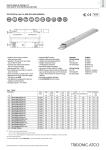
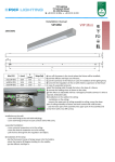
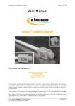
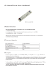
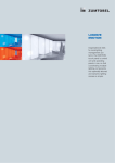
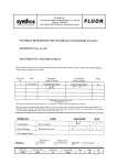
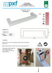
FL ballasts Electronic dimming EL T5 TC-L PCA T5 ECO lp Y II, 14 – 80 W ECO T5 Product description •Processor-controlled ballast with y II inside •Highest possible energy class CELMA EEI = A1 BAT1 •Noise-free precise control via DALI or DSI signal, switchDIM or corridorFUNCTION •Nominal life up to 100,000 h (at ta 50 °C with a failure rate max. 0.2 % per 1,000 h) •Multi-lamp management •OEM-specific reserved memory areas •5-year guarantee Interfaces •DSI 21 6 •DALI side fixing feature •switchDIM (with memory function + selectable dimming rate) L D •corridorFUNCTION (3 preprogrammed profiles) •Integrated SMART interface for function with 4,1 30 Functions Ø4,1 SMART Sensor 5D 19f and corridorFUNCTION plugs •Intelligent Temperature Guard (overtemperature protection) •Intelligent Voltage Guard (overvoltage indication and undervoltage shutdown) •Optimum filament heating in any dimmer setting •Disconnection of filament heating from a dimming level of approx. 90 % for maximum energy efficiency (SMART-Heating concept) •corridorFUNCTION with ambient light control •Automatically triggered emergency lighting value in DC mode, 15 % •For emergency lighting systems as per EN 50172 •Automatic start after replacement of defective lamps •Automatic shutdown if the lamp is faulty Technical data Mains voltage range 220 – 240 V AC voltage range 198 – 264 V DC voltage range 176 – 280 V (lamp start ≥ 198 V DC) Mains frequency 0 / 50 / 60 Hz Overvoltage protection 320 V AC, 1 h Typ. power input on standby < 0.2 W Protective hot restart 0.5 s for AC / 0.2 s for DC Dimming range 1 – 100 % Lamp start possible from 1% Operating frequency ~ 40 – 130 kHz Type of protection IP20 Ordering data Type È For luminaires with 1 lamp Standards, page 3 PCA 1x21/39 T5 ECO lp Y II Wiring diagrams and installation examples, page 8 PCA 1x14/24 ECO lp Y II PCA 1x28/54 T5 ECO lp Y II PCA 1x35/49/80 T5 ECO lp Y II Packaging, carton Packaging, pallet 22185094 10 pc(s). 760 pc(s). 0.342 kg 22185101 10 pc(s). 760 pc(s). 0.233 kg 22185099 10 pc(s). 760 pc(s). 0.242 kg 22185096 10 pc(s). 760 pc(s). 0.243 kg 22185095 10 pc(s). 760 pc(s). 0.272 kg 22185102 10 pc(s). 760 pc(s). 0.270 kg Article number Weight per pc. For luminaires with 2 lamps PCA 2x14/24 ECO lp Y II PCA 2x21/39 T5 ECO lp Y II PCA 2x28/54 T5 ECO lp Y II PCA 2x35/49 T5 ECO lp Y II PCA 2x80 T5 ECO lp Y II Data sheet 08/15-FD003-7 Subject to change without notice. www.tridonic.com 22185100 10 pc(s). 640 pc(s). 0.332 kg 22185097 10 pc(s). 760 pc(s). 0.260 kg 22185098 10 pc(s). 640 pc(s). 0.343 kg 1 FL ballasts Electronic dimming Specific technical data Lamp wattage Lamp type Type Article number Dimensions LxWxH Hole spacing Lamp D power2 Circuit power2 EEI Current at λ at 50 Hz 230 V2 50 Hz 230 V tc point Ambient max. temperature ta3 For luminaires with 1 lamp 1 x 14 W T5 1 x 24 W T5 1 x 21 W T5 1 x 36 W TC-L 1 x 39 W T5 1 x 40 W TC-L 1 x 28 W T5 1 x 54 W T5 1 x 35 W T5 1 x 49 W T5 1 x 55 W TC-L 1 x 80 W T5 1 x 80 W TC-L PCA 1x14/24 ECO lp Y II 22185094 360 x 30 x 21 mm 350 mm 14 W 16.0 W A1 BAT 0.08 A 0.95 80 °C -25 ... 70 °C 22185094 360 x 30 x 21 mm 350 mm 23 W 25.5 W A1 BAT 0.12 A 0.97 80 °C -25 ... 70 °C 22185101 360 x 30 x 21 mm 350 mm 21 W 23.0 W A1 BAT 0.11 A 0.95 80 °C -25 ... 70 °C 22185101 360 x 30 x 21 mm 350 mm 32 W 35.5 W A1 BAT 0.16 A 0.96 80 °C -25 ... 65 °C 22185101 360 x 30 x 21 mm 350 mm 38 W 41.5 W A1 BAT 0.19 A 0.97 80 °C -25 ... 65 °C 22185101 360 x 30 x 21 mm 350 mm 40 W 43.0 W A1 BAT 0.20 A 0.98 80 °C -25 ... 65 °C 22185099 360 x 30 x 21 mm 350 mm 28 W 30.5 W A1 BAT 0.14 A 0.95 80 °C -25 ... 75 °C PCA 1x35/49/80 T5 ECO lp Y II 22185099 360 x 30 x 21 mm 350 mm 54 W 58.0 W A1 BAT 0.26 A 0.98 80 °C -25 ... 70 °C 22185096 360 x 30 x 21 mm 350 mm 35 W 39.0 W A1 BAT 0.18 A 0.95 85 °C -25 ... 75 °C PCA 1x35/49/80 T5 ECO lp Y II 22185096 360 x 30 x 21 mm 350 mm 49 W 53.0 W A1 BAT 0.25 A 0.97 80 °C -25 ... 70 °C 22185096 360 x 30 x 21 mm 350 mm 55 W 60.0 W A1 BAT 0.28 A 0.97 80 °C -25 ... 60 °C PCA 1x35/49/80 T5 ECO lp Y II 22185096 360 x 30 x 21 mm 350 mm 80 W 85.5 W A1 BAT 0.40 A 0.99 80 °C -25 ... 60 °C 22185096 360 x 30 x 21 mm 350 mm 80 W 85.5 W A1 BAT 0.36 A 0.98 80 °C -25 ... 60 °C -25 ... 70 °C PCA 1x14/24 ECO lp Y II PCA 1x21/39 T5 ECO lp Y II PCA 1x21/39 T5 ECO lp Y II PCA 1x21/39 T5 ECO lp Y II PCA 1x21/39 T5 ECO lp Y II PCA 1x28/54 T5 ECO lp Y II PCA 1x28/54 T5 ECO lp Y II PCA 1x35/49/80 T5 ECO lp Y II PCA 1x35/49/80 T5 ECO lp Y II For luminaires with 2 lamps 2 x 14 W T5 2 x 18 W TC-L 2 x 24 W T5 2 x 24 W TC-L 2 x 21 W T5 2 x 36 W TC-L 2 x 39 W T5 2 x 40 W TC-L 2 x 28 W T5 2 x 54 W T5 2 x 35 W T5 2 x 49 W T5 2 x 55 W TC-L 2 x 80 W T5 PCA 2x14/24 ECO lp Y II 22185095 360 x 30 x 21 mm 350 mm 28 W 30.5 W A1 BAT 0.14 A 0.96 80 °C PCA 2x14/24 ECO lp Y II 22185095 360 x 30 x 21 mm 350 mm 32 W 38.0 W A1 BAT 0.15 A 0.96 80 °C -25 ... 65 °C 22185095 360 x 30 x 21 mm 350 mm 45 W 49.5 W A1 BAT 0.22 A 0.98 80 °C -25 ... 65 °C PCA 2x21/39 T5 ECO lp Y II 22185095 360 x 30 x 21 mm 350 mm 44 W 49.0 W A1 BAT 0.21 A 0.98 80 °C -25 ... 65 °C 22185102 360 x 30 x 21 mm 350 mm 41 W 45.5 W A1 BAT 0.21 A 0.96 85 °C -25 ... 70 °C 22185102 360 x 30 x 21 mm 350 mm 64 W 71.0 W A1 BAT 0.31 A 0.98 85 °C -25 ... 65 °C 22185102 360 x 30 x 21 mm 350 mm 76 W 82.0 W A1 BAT 0.37 A 0.98 85 °C -25 ... 65 °C 22185102 360 x 30 x 21 mm 350 mm 80 W 86.0 W A1 BAT 0.40 A 0.99 85 °C -25 ... 65 °C 22185100 425 x 30 x 21 mm 415 mm 56 W 60.5 W A1 BAT 0.28 A 0.96 80 °C -25 ... 70 °C 22185100 425 x 30 x 21 mm 415 mm 108 W 116.5 W A1 BAT 0.51 A 0.99 85 °C -25 ... 55 °C PCA 2x35/49 T5 ECO lp Y II 22185097 360 x 30 x 21 mm 350 mm 70 W 74.5 W A1 BAT 0.34 A 0.97 80 °C -25 ... 65 °C 22185097 360 x 30 x 21 mm 350 mm 98 W 105.5 W A1 BAT 0.49 A 0.98 85 °C -25 ... 60 °C PCA 2x80 T5 ECO lp Y II 22185098 425 x 30 x 21 mm 415 mm 110 W 117.0 W A1 BAT 0.52 A 0.99 80 °C -25 ... 55 °C 22185098 425 x 30 x 21 mm 415 mm 160 W 167.0 W A1 BAT 0.74 A 0.99 80 °C -25 ... 55 °C PCA 2x14/24 ECO lp Y II PCA 2x14/24 ECO lp Y II PCA 2x21/39 T5 ECO lp Y II PCA 2x21/39 T5 ECO lp Y II PCA 2x21/39 T5 ECO lp Y II PCA 2x28/54 T5 ECO lp Y II PCA 2x28/54 T5 ECO lp Y II PCA 2x35/49 T5 ECO lp Y II PCA 2x80 T5 ECO lp Y II 1 According to the EU directives on ecodesign requirements (EC) No. 245/2009 and (EC) No. 347/2010. 2 Valid at 100 % dimming level. 3 +10 °C to ta max: unrestricted dimming. -25 °C to +10 °C: unrestricted dimming from 100 % to 30 %. -25 °C to +10 °C, dimming below 30 %: malfunction possible but no damage to ECG. This applies to AC and DC operation. Data sheet 08/15-FD003-7 Subject to change without notice. www.tridonic.com 2 FL ballasts Electronic dimming Standards EN 55015 EN 60929 EN 61000-3-2 EN 61347-2-3 EN 61547 Suitable for emergency installations according to EN 50172 CISPR 15 CISPR 22 IEC 60929 IEC 61000-3-2 IEC 61347-2-3 IEC 61547 IEC 62386 (according to DALi standard V1) Lamp starting characteristics Warm start Starting time 0.5 s with AC Starting time 0.2 s with DC Start at any dimming level AC operation Mains voltage 220–240 V 50/60 Hz 198–264 V 50/60 Hz including safety tolerance (±10 %) 198–254 V 50/60 Hz including performance tolerance (+6 % / -8 %) DC operation 220–240 V 0 Hz 198–254 V 0 Hz certain lamp start 176–280 V 0 Hz operating range Use in emergency lighting installations according to EN 50172 or for emergency luminaires according to EN 61347-2-3 appendix J. Mains current for defective or missing lamps at DC operation < 35 mA. Mains currents in DC operation (at 15 % light output) Type PCA 1x14/24 T5 ECO lp Y II PCA 1x21/39 T5 ECO lp Y II PCA 1x28/54 T5 ECO lp Y II PCA 1x35/49/80 T5 ECO lp Y II PCA 2x14/24 T5 ECO lp Y II PCA 2x21/39 T5 ECO lp Y II PCA 2x28/54 T5 ECO lp Y II PCA 2x35/49 T5 ECO lp Y II PCA 2x80 T5 ECO lp Y II Type PCA 1x14/24 T5 ECO lp Y II PCA 1x21/39 T5 ECO lp Y II PCA 1x28/54 T5 ECO lp Y II PCA 1x35/49/80 T5 ECO lp Y II PCA 2x14/24 T5 ECO lp Y II PCA 2x21/39 T5 ECO lp Y II Temperature range Unlimited dimming range from 10 °C to ta max. -25 °C to 10 °C: dimming operation from 100 % to 30 %. If dimm level goes below 30 % malfunction possible, but no electronic ballast damage. This applies to AC and DC operation. Wattage 1 x 14 W 1 x 24 W 1 x 21 W 1 x 36 W 1 x 39 W 1 x 40 W 1 x 28 W 1 x 54 W 1 x 35 W 1 x 49 W 1 x 55 W 1 x 80 W 1 x 80 W 2 x 14 W 2 x 18 W 2 x 24 W 2 x 24 W 2 x 21 W 2 x 36 W 2 x 39 W 2 x 40 W 2 x 28 W 2 x 54 W 2 x 35 W 2 x 49 W 2 x 55 W 2 x 80 W Mains current at Mains current at Un = 220 VDC Un = 275 VDC 0.04 A 0.04 A 0.05 A 0.05 A 0.05 A 0.04 A 0.07 A 0.06 A 0.07 A 0.07 A 0.07 A 0.06 A 0.06 A 0.06 A 0.11 A 0.10 A 0.07 A 0.06 A 0.09 A 0.08 A 0.11 A 0.10 A 0.14 A 0.13 A 0.13 A 0.12 A 0.07 A 0.06 A 0.07 A 0.06 A 0.10 A 0.09 A 0.09 A 0.09 A 0.08 A 0.07 A 0.12 A 0.11 A 0.13 A 0.12 A 0.13 A 0.12 A 0.10 A 0.10 A 0.20 A 0.18 A 0.12 A 0.11 A 0.16 A 0.15 A 0.20 A 0.19 A 0.27 A 0.25 A Wattage 1 x 14 W 1 x 24 W 1 x 21 W 1 x 36 W 1 x 39 W 1 x 40 W 1 x 28 W 1 x 54 W 1 x 35 W 1 x 49 W 1 x 55 W 1 x 80 W 1 x 80 W 2 x 14 W 2 x 18 W 2 x 24 W 2 x 24 W 2 x 21 W 2 x 36 W 2 x 39 W 2 x 40 W 2 x 28 W 2 x 54 W 2 x 35 W 2 x 49 W 2 x 55 W 2 x 80 W AC-BLF at U = 230 VAC 1.00 1.01 0.99 0.97 1.01 1.05 0.98 1.02 1.00 1.00 1.02 1.02 1.04 1.01 0.90 1.00 0.98 0.97 0.97 0.98 1.05 1.00 1.00 1.01 1.02 1.03 1.02 Ballast lumen factor AC operation (AC-BLF) EN 60929 8.1 Light output level in DC operation Default value is 15 % Emergency units The “PCA T5 ECO lp y II” ballasts are compatible with all emergency units from Tridonic. See the table in the data sheet. Also all “5-pole” emergency units can be used. When used with other emergency units tests are necessary. Lamp type T5 T5 T5 TC-L T5 TC-L T5 T5 T5 T5 TC-L T5 TC-L T5 TC-L T5 TC-L T5 TC-L T5 TC-L T5 T5 T5 T5 TC-L T5 PCA 2x28/54 T5 ECO lp Y II PCA 2x35/49 T5 ECO lp Y II PCA 2x80 T5 ECO lp Y II Lamp type T5 T5 T5 TC-L T5 TC-L T5 T5 T5 T5 TC-L T5 TC-L T5 TC-L T5 TC-L T5 TC-L T5 TC-L T5 T5 T5 T5 TC-L T5 The ballast lumen factor for AC operation (AC-BLF) does not alter from Un = 198 V AC to Un = 254 V AC. The ballast lumen factor for DC operation (DC-BLF) on the basis of an automatic power reduction of the ballasts (default value is 15 %) will be smaller than AC. It does not alter in the DC operating range (198–264 V DC). Data sheet 08/15-FD003-7 Subject to change without notice. www.tridonic.com 3 FL ballasts Electronic dimming Dimming Dimming curve is adapted to the eye sensitiveness. Dimming range 1 % to 100 % Digital control with: •DSI signal: 8 bit Manchester Code Speed 1 % to 100 % in 1.4 s •DALI signal: 16 bit Manchester Code Maximum speed 1 % to 100 % in 550 ms (adjustable between 100 ms and 90 s) Programmable parameter: Minimum dimming level Maximum dimming level Default minimum = 1 % Default maximum = 100 % Dimming characteristics PCA T5 ECO lp Y II Energy saving PCA T5 ECO lp Y II digital dimming value mains power in % 255 100 Control input (DA/D1, DA/D2) Digital DALI/DSI signal or a push-to-make switch (switchDIM) or a motion detector (corridorFUNCTION) can be wired on the same terminals (DA/D1 and DA/ D2). 0 Digital signal DALI/DSI The control input is non-polar and protected against accidental connection with a mains voltage up to 264 V. The control signal is not SELV. Control cable has to be installed in accordance to the requirements of low voltage installations. Different functions depending on each module. SMART interface An additional interface for the direct connection of the SMART-Sensor 5D 19f1) or corridorFUNCTION plugs. Application and functionallity see corridorFUNCTION user manual. SMART-Sensor 5D 19f1) light sensor operating mode: The sensor registers actual ambient light and maintains the individually defined constant lux level. After every mains reset the SMART interface auto matically checks for an installed sensor. With the sensor installed the PCA T5 ECO lp y II automatically runs in the constant lux level mode. ON/OFF switch via mains, switchDIM or DSI signal. DSI signal = 0 switches off, DSI signal ≥ 1 switches on. With switchDIM signals it is possible to change the controlled light level temporarily. Temporarily means that after a switching cycle OFF/ ON command the ballast will start at the preset value determined by the SMART-Sensor 5D 19f. The installation of the two wire bus is according to the appropriate low voltage regulations. SMART-Sensor 5D 19f: article number 86459169 1) switchDIM Integrated switchDIM function allows a direct connection of a push to make switch for dimming and switching. Brief push (< 0.6 s) switches ballast ON and OFF. The ballasts switch-ON at light level set at switch-OFF. After switch ON the last settet dimming level will be activated again. When the push to make switch is held, PCA ballasts are dimmed. After repush the PCA is dimmed in the opposite direction. The switchDIM fade time is set to 3 s from min. to max. in the factory settings. With a 20 s push to the push to make switch this fade time can be changed to 6 s. In this instance the switchDIM application will be synchronized to 50 % light level after 10 s and after 20 s the light level rises to 100 % with the new fade 90 225 DALI 200 175 80 DSI 150 60 125 50 100 40 75 30 50 20 25 10 0 0 10 20 30 40 50 60 70 80 90 100 relative lighting level in % 100 90 80 70 60 50 40 30 20 15 10 5 4 3 2 1 dimming level in % Dimming characteristics as seen by the human eye time. At every synchronizsation (10 s keystroke) the device will reset to 3 s (factory setting) In installations with PCAs with different dimming levels or opposite dimming directions (e.g. after a system extension), all PCAs can be synchronized to 50 % dimming level by a 10 s push. Use of push to make switch with indicator lamp is not permitted. switchDIM and corridorFUNCTION are very simple tools for controlling ballasts with conventional momentaryaction switches or motion sensors. To ensure correct operation a sinusoidal mains voltage with a frequency of 50 Hz or 60 Hz is required at the control input. Special attention must be paid to achieving clear zero crossings. Serious mains faults may impair the operation of switchDIM and corridorFUNCTION. corridorFUNCTION To activate the corridorFUNCTION a voltage of 230 V simply has to be applied for five minutes at switchDIM connection. The unit will then switch automatically to the corridorFUNCTION. Note: If the corridorFUNCTION is wrongly activated in a switchDIM system (for example a switch is used instead of pushbutton), there is the option of installing a pushbutton and deactivating the corridorFUNCTION mode by five short pushes of the button within three seconds. The corridorFUNCTION offers the added benefit of a second and third preprogrammed profile, which can be activated by the corridorFUNCTION plugs. It is also possible to combine the corridorFUNCTION with the SMART-Sensor 5D 19f light sensor. Application and functionallity of profiles see user manual of the corridorFUNCTION. Data sheet 08/15-FD003-7 Subject to change without notice. 70 www.tridonic.com 2 3 4 N L 6 D1 7 D2 switchDIM PCA T5 ECO lp Y II 2 3 4 N L 6 D1 7 D2 corridorFUNCTION PCA T5 ECO lp Y II 2 3 4 DSI 6 D1 7 D2 DSI PCA T5 ECO lp Y II 2 3 4 DALI 6 DA 7 DA DALI PCA T5 ECO lp Y II 4 FL ballasts Electronic dimming Loading of automatic circuit breakers (Limitation via inrush current) Automatic circuit breaker type Installation Ø PCA 1x14/24 T5 ECO lp Y II PCA 1x21/39 T5 ECO lp Y II C10 C13 C16 C20 B10 B13 B16 B20 1.5 mm2 1.5 mm2 1.5 mm2 2.5 mm2 1.5 mm2 1.5 mm2 1.5 mm2 2.5 mm2 50 80 150 180 25 40 75 90 Inrush current (1.5 mm2) Inrush current (2.5 mm2) Imax time Imax time 19.3 A 144 µs 19.6 A 147 µs PCA 1x28/54 T5 ECO lp Y II 34 50 76 86 17 25 38 43 25.3 A 190 µs 25.1 A 192 µs 22 32 46 52 11 16 23 26 26.6 A 235 µs 28.5 A 223 µs PCA 2x14/24 T5 ECO lp Y II 16 22 28 34 8 11 14 17 31.2 A 271 µs 31.2 A 273 µs 22 32 44 50 11 16 22 25 28.1 A 227 µs 28.3 A 227 µs PCA 2x28/54 T5 ECO lp Y II 16 22 28 34 8 11 14 17 37.2 A 207 µs 38.8 A 203 µs 16 22 30 36 8 11 15 18 28.9 A 288 µs 30.3 A 282 µs PCA 1x35/49/80 T5 ECO lp Y II PCA 2x21/39 T5 ECO lp Y II PCA 2x35/49 T5 ECO lp Y II PCA 2x80 T5 ECO lp Y II 16 22 30 34 8 11 15 17 33.0 A 241 µs 33.9 A 240 µs 8 12 18 20 4 6 9 10 48.3 A 261 µs 50.1 A 258 µs Continuous operation: to calculate the protective saftey switch see main current, page 2 Intelligent Voltage Guard Intelligent Voltage Guard is the name of the electronic monitor from Tridonic. This innovative feature of the PCA family of control gear from Tridonic immediately shows if the mains voltage rises above certain thresholds. Measures can then be taken quickly to prevent damage to the control gear. •If the mains voltage rises above approx. 318 Vrms (voltage depends on the ballast type), the lamp starts flashing on and off. •To avoid a damage of the device the mains supply has to be switched off at this signal. Data sheet 08/15-FD003-7 Subject to change without notice. www.tridonic.com Intelligent Temperature Guard The intelligent temperature guard protects the PCA T5 ECO lp y II from thermal overheating by reducing the output power or switching off in case of operation above the thermal limits of the luminaire or ballast. Depending on the luminaire design, the ITG operates at about 5 to 10 °C above tc temperature. 5 FL ballasts Electronic dimming Harmonic distortion in the mains supply (at 230 V / 50 Hz) Type PCA 1x14/24 T5 ECO lp Y II PCA 1x21/39 T5 ECO lp Y II PCA 1x28/54 T5 ECO lp Y II PCA 1x35/49/80 T5 ECO lp Y II PCA 2x14/24 T5 ECO lp Y II PCA 2x21/39 T5 ECO lp Y II PCA 2x28/54 T5 ECO lp Y II PCA 2x35/49 T5 ECO lp Y II PCA 2x80 T5 ECO lp Y II Lamp type T5 T5 T5 TC-L T5 TC-L T5 T5 T5 T5 TC-L T5 TC-L T5 TC-L T5 TC-L T5 TC-L T5 TC-L T5 T5 T5 T5 TC-L T5 Wattage 1 x 14 W 1 x 24 W 1 x 21 W 1 x 36 W 1 x 39 W 1 x 40 W 1 x 28 W 1 x 54 W 1 x 35 W 1 x 49 W 1 x 55 W 1 x 80 W 1 x 80 W 2 x 14 W 2 x 18 W 2 x 24 W 2 x 24 W 2 x 21 W 2 x 36 W 2 x 39 W 2 x 40 W 2 x 28 W 2 x 54 W 2 x 35 W 2 x 49 W 2 x 55 W 2 x 80 W Lamp type T5 T5 T5 TC-L T5 TC-L T5 T5 T5 T5 TC-L T5 TC-L T5 TC-L T5 TC-L T5 TC-L T5 TC-L T5 T5 T5 T5 TC-L T5 Wattage 1 x 14 W 1 x 24 W 1 x 21 W 1 x 36 W 1 x 39 W 1 x 40 W 1 x 28 W 1 x 54 W 1 x 35 W 1 x 49 W 1 x 55 W 1 x 80 W 1 x 80 W 2 x 14 W 2 x 18 W 2 x 24 W 2 x 24 W 2 x 21 W 2 x 36 W 2 x 39 W 2 x 40 W 2 x 28 W 2 x 54 W 2 x 35 W 2 x 49 W 2 x 55 W 2 x 80 W THD 3 5 7 9 11 9 9 9 8 7 6 10 6 10 10 7 6 6 8 7 5 6 10 7 6 6 10 8 9 7 6 5 6 6 4 4 4 4 4 4 6 8 5 5 5 1 1 1 1 7 4 4 4 7 6 5 6 4 4 3 2 3 2 2 1 2 1 2 3 1 1 1 3 2 2 2 3 1 1 1 2 1 1 1 2 2 3 3 2 1 1 1 2 1 3 3 1 1 1 1 1 1 1 4 1 1 1 2 1 1 1 1 1 1 1 2 1 1 1 2 1 3 2 1 1 1 1 1 1 1 4 2 1 1 2 1 2 1 1 1 1 1 2 1 1 1 2 1 3 2 2 1 1 2 2 1 1 2 1 1 1 2 1 2 1 1 1 Operating voltage Type PCA 1x14/24 T5 ECO lp Y II PCA 1x21/39 T5 ECO lp Y II PCA 1x28/54 T5 ECO lp Y II PCA 1x35/49/80 T5 ECO lp Y II PCA 2x14/24 T5 ECO lp Y II PCA 2x21/39 T5 ECO lp Y II PCA 2x28/54 T5 ECO lp Y II PCA 2x35/49 T5 ECO lp Y II PCA 2x80 T5 ECO lp Y II Uout 430 V 430 V 430 V 430 V 430 V 430 V 430 V 430 V 430 V 430 V 430 V 430 V 430 V 430 V 430 V 430 V 430 V 430 V 430 V 430 V 430 V 430 V 430 V 430 V 430 V 430 V 430 V Data sheet 08/15-FD003-7 Subject to change without notice. www.tridonic.com 6 FL ballasts Electronic dimming Humidity: 5 % up to max. 85 %, not condensed (max. 56 days/year at 85 %) Storage temperature:-40 °C up to max. +80 °C The devices have to be within the specified temperature range (ta) before they can be operated. Expected life-time Type PCA 1x14/24 T5 ECO lp Y II PCA 1x21/39 T5 ECO lp Y II PCA 1x28/54 T5 ECO lp Y II PCA 1x35/49/80 T5 ECO lp Y II PCA 2x14/24 T5 ECO lp Y II PCA 2x21/39 T5 ECO lp Y II PCA 2x28/54 T5 ECO lp Y II PCA 2x35/49 T5 ECO lp Y II PCA 2x80 T5 ECO lp Y II Lamp type Wattage T5 1 x 14 W T5 1 x 24 W T5 1 x 21 W TC-L 1 x 36 W T5 1 x 39 W TC-L 1 x 40 W T5 1 x 28 W T5 1 x 54 W T5 1 x 35 W T5 1 x 49 W TC-L 1 x 55 W T5 1 x 80 W TC-L 1 x 80 W T5 2 x 14 W TC-L 2 x 18 W T5 2 x 24 W TC-L 2 x 24 W T5 2 x 21 W TC-L 2 x 36 W T5 2 x 39 W TC-L 2 x 40 W T5 2 x 28 W T5 2 x 54 W T5 2 x 35 W T5 2 x 49 W TC-L 2 x 55 W T5 2 x 80 W tc Life-time tc Life-time tc Life-time tc Life-time tc Life-time tc Life-time tc Life-time tc Life-time tc Life-time tc Life-time tc Life-time tc Life-time tc Life-time tc Life-time tc Life-time tc Life-time tc Life-time tc Life-time tc Life-time tc Life-time tc Life-time tc Life-time tc Life-time tc Life-time tc Life-time tc Life-time tc Life-time ta = 40 °C 55 °C > 100,000 h 55 °C > 100,000 h 50 °C > 100,000 h 55 °C > 100,000 h 50 °C > 100,000 h 55 °C > 100,000 h 50 °C > 100,000 h 55 °C > 100,000 h 55 °C > 100,000 h 55 °C > 100,000 h 65 °C > 100,000 h 65 °C > 100,000 h 65 °C > 100,000 h ta = 50 °C 65 °C > 100,000 h 65 °C > 100,000 h 60 °C > 100,000 h 65 °C > 100,000 h 60 °C > 100,000 h 65 °C > 100,000 h 60 °C > 100,000 h 65 °C > 100,000 h 65 °C > 100,000 h 60 °C > 100,000 h 70 °C > 100,000 h 70 °C > 100,000 h 70 °C > 100,000 h ta = 60 °C 75 °C > 100,000 h 75 °C > 100,000 h 70 °C > 100,000 h 75 °C > 100,000 h 70 °C > 100,000 h 75 °C > 100,000 h 70 °C > 100,000 h 75 °C 90,000 h 75 °C > 100,000 h 70 °C > 100,000 h 80 °C 50,000 h 80 °C 50,000 h 80 °C 50,000 h 50 °C 60 °C 70 °C > 100,000 h > 100,000 h > 100,000 h 55 °C 65 °C 75 °C > 100,000 h > 100,000 h 90,000 h 55 °C 65 °C 75 °C > 100,000 h > 100,000 h 90,000 h 55 °C 65 °C 75 °C > 100,000 h > 100,000 h 90,000 h 55 °C 65 °C 75 °C > 100,000 h > 100,000 h > 100,000 h 60 °C 70 °C 80 °C > 100.000 h > 100.000 h 90.000 h 60 °C 70 °C 80 °C > 100.000 h > 100.000 h 70.000 h 60 °C 70 °C 80 °C > 100.000 h > 100.000 h 80.000 h 55 °C 60 °C 70 ° > 100,000 h > 100,000 h > 100,000 h x 65 °C 75 °C > 100,000 h 70,000 h x 55 °C 65 °C 75 °C > 100,000 h > 100,000 h 80,000 h 65 °C 75 °C 80 °C > 100,000 h 80,000 h 50,000 h x 65 °C 75 °C > 100,000 h 80,000 h x 65 °C 70 °C x > 100,000 h 80,000 h x x = not permitted Data sheet 08/15-FD003-7 Subject to change without notice. www.tridonic.com 7 FL ballasts Electronic dimming Installation instructions Wiring type and cross section The wiring can be solid cable with a cross section of 0.5 to 0.75 mm² for push terminal and 0.5 mm² for IDC terminal. For the push-wire connection you have to strip the insulation (8–9 mm). Wiring advice The lead length is dependent on the capacitance of the cable. Ballast Terminal Maximum capacitance allowed Type Cold Hot Cold Hot 13, 14 15, 16 200 pF 100 pF 12, 13, 14 10, 11, 15, 16 200 pF 100 pF PCA 1xx T5 ECO lp Y II wire preparation: 0.5 – 0.75 mm² PCA 2xx T5 ECO lp Y II With standard solid wire 0.5/0.75 mm² the capacitance of the lead is 30–80 pF/m. This value is influenced by the way the wiring is made. Lamp connection should be made with symmetrical wiring. Hot leads (10, 11, 15, 16) and cold leads (12, 13, 14) should be separated as much as possible. When using two or more dimmable ballasts in one luminaire with separate dimming controls, the lamp leads must be kept separate. 8 – 9 mm Sensor wires Sensor wires must be routed separately from the lamp wires and mains cables otherwise the lighting control system may malfunction. If separate routing is not possible (for reasons of space) shielded lamp wires and mains cables must be used. Loosen wire through twisting and pulling Dimmable ballasts from Tridonic have to be earthed. 16 15 14 13 2 3 4 * * control signal 6 7 16 15 14 13 12 11 10 2 3 4 DA/D1 * * control signal DA/D2 * leads 15, 16: keep wires short, max. 1.0 m leads 13, 14: max. 2.0 m; ballast must be earthed * * digital signal (DSI), DALI or switchDIM 6 7 DA/D1 DA/D2 * leads 10, 11, 15, 16: keep wires short, max. 1.0 m leads 12, 13, 14: max. 2.0 m; ballast must be earthed * * digital signal (DSI), DALI or switchDIM PCA T5 ECO lp Y II 1x14–80 W PCA T5 ECO lp Y II 2x14–80 W Dimmable ballasts from Tridonic have to be earthed. RFI •Connection to the lamps of the hot leads must be kept as short as possible •Mains leads should be kept apart from lamp leads (ideally 5–10 cm distance) •Do not run mains leads adjacent to the electronic ballast •Twist the lamp leads •Keep the distance of lamp leads from the metal work as large as possible •Mains wiring to be twisted when through wiring •Keep the mains leads inside the luminaire as short as possible Operation on DC voltage Our ballasts are construed to operate DC voltage and pulsed DC voltage. To operate ballasts with pulsed DC voltage the polarity is absolute mandatory. 2 3 4 6 7 Isolation and electric strength testing of luminaires Electronic devices can be damaged by high voltage. This has to be considered during the routine testing of the luminaires in production. According to IEC 60598-1 Annex Q (informative only!) or ENEC 303-Annex A, each luminaire should be submitted to an isolation test with 500 VDC for 1 second. This test voltage should be connected between the interconnected phase and neutral terminals and the earth terminal. The isolation resistance must be at least 2 MΩ. + – D1 D2 General advise Electronic ballasts are virtually noise free. Magnetic fields generated during the ignition cycle can cause some background noise but only for a few milliseconds. As an alternative, IEC 60598-1 Annex Q describes a test of the electrical strength with 1500 VAC (or 1.414 x 1500 VDC). To avoid damage to the electronic devices this test must not be conducted. For further technical information please visit www.tridonic.com Data sheet 08/15-FD003-7 Subject to change without notice. www.tridonic.com 8