1
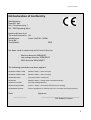
USER MANUAL SL250 STANDARD 500W 500W / 700W English SL 250-2010 Table of Contents: Table of Contents 2 Introduction 3 EU Declaration of Conformity 4 General Description 5 Transport/Handling/Putting into Operation/Storage 6 Technical Data, Safety Rules 7 Overview/ - General Description 8 Operation for Vacuum function 10 Control for arm and yoke 10 Important Operation (vacuum & electric functions) 11 Electric Functions 11 Charger & Battery Case 12 View of Vacuum system (top and bottom of machine) 13 Control Box 14 Switches and Alarms 14 Control Panel for arm and yoke 15 Load Diagram 16 Stop-Down Troubleshooting of SmartLIFT 17 - 27 Information and manual charger 28 Wiring Diagrams 29 - 33 2 English SL 250-2010 Introduction Congratulations on your new Smart LIFT. Smart Lift has been designed and constructed so as to safeguard product users against accidents as far as at all possible. Unfortunately, certain functions in a machine cannot be safeguarded. This is why safety rules have been prepared by way of warnings in this instruction. Read these safety rules on the following pages before putting your Smart LIFT into operation, and imagine how you may, in your daily use of the machine, ensure that warnings and safety rules will be adhered to. Manufacturer: Smartlift ApS N.A. Christensensvei 7 7900 Nykøbing Mors Danmark Importer: Avd. Oslo Enebakkveien 441 B NO-1290 OSLO Avd. Trondheim Fremo næringspark NO-7234 LER Avd. Bergen Midttunlia 17 NO-5224 NESTTUN Kontakt oss Tel. 23 19 11 00 Fax. 23 19 11 01 [email protected] www.instant.no 3 English SL 250-2010 EU Declaration of Conformity Manufacturer Smartlift ApS N.A. Christensensvej 7 DK - 7900 Nykøbing Mors Hereby declares that: The machine/system: Lift Model/type: Smart Lift/250 – 500W Serial No.: Year/Month: 2010 has been made in conformity with Council directive - Machine directive 2006/42EF - Low voltage directive 2006/95/EF - EMC directive 2004/108/EF The following standards have been applied: DS/EN ISO 12100-1:2005 (Machine Safety – Basic concepts) DS/EN ISO 12100-2:2005 (Machine Safety – Basic concepts) DS/EN 1050:1997 (Principles of Risk Assessment) DS/EN 294 (Machine Safety – Danger Areas and Safe Distances) DS/EN 1757-1:2001 (Lift with walking operator) DS/EN 13155/A1:2005 (Cranes – Safety – not fastened lift devices for loading) DS/EN 60204-32:2001 (Electric equipment on machines part 32 : Provisions for lifting machines) Date: ____________ Signature: ____________________________________ Ole Kobæk, Director 4 English SL 250-2010 General Description/List of Spare Parts Product Numbe r 1a Pump 107 1 1b Pump 007 1 2 Suction Cup diam. 250 4 3 Check Valve ½", vacuum 1 4 Replacement rubber t/suction cup 1 5 Slide Valve w/lock, vacuum 1 6 Vacuummeter diam.63 ¼", stainless 1 7 Vacuum filter VTF-12 1 8 Loose filter for VTF-12 1 10 Hose Set 1 11 Hose Coupling 2 12 Spiral Hoses 2 13 Vacuum Guard 1 14 Vacuum Hose diam.19 1 15 Alarm Light, Vacuum 1 16 Acoustic alarm, Vacuum 1 17 Line Filter 1 19 Stainless Spring 4 20 Clamp MRX.80 P-M10-25 6 21 Actuator – Tilting function IP66 1 22 Actuator – Side Change IP66 1 23 Actuator – Telescopic Arm IP66 1 24 Actuator – Lift Arm IP 66 2 25 Battery 62 AK/Battery Case 2 26 Charger CTEK MULTI 1 27 Wheel, EK-MASSIV 2 28 Wheel, GK-MASSIV 1 29 FGP 10" fork with plate 1 30 Supporting Wheel 2 31 Safety Switch/Telemecanique 1 32 Control Panel 1 33 Emergency Stop 1 34 Control/MULTIMOC, Lift Arm 1 35 Control/MULTIMOC, Telescopic Arrm/Tilt 1 36 Control/MULTIMOC, Side Change 1 37 CE Connector 1 38 Ermax Main Switch 24 V 1 39 Fuse 30 Amperes Control Pos.no. Vacuum Power Supply Wheels 24 V Various 40 Lock Split 1 41 Lift Eye 1 42 Lock Fitting, transport frame 1 44 Handle 3 45 Weight Blocks 30 mm 10 46 Supporting Leg 2 5 English SL 250-2010 Drive 47 48 47a Motor 500 W/24 V 1 On/OFF Switch for Drive Motor 1 47b Fuse 80 Amperes Motor 1 48 Regulating Lever 1 49 Curtis Motor Control 1 50 Safety Clamp 1 51 Safety Switch 1 52 Forward and Back Switch 1 53 Protective Cap for forward and back switch 1 Transport/Handling Smart Lift is for indoor use. May not be exposed to rain and snow. Prior to transport, switch off all electronics on main switch (pos. 38). Smart Lift to be fastened securely in truck/trailer for transport and protected against rain and snow. Lifting by crane or similar: Always lift Smart Lift in lift eye intended for this purpose (pos. 41). NEVER lift under Smart LIFT by forks (truck and similar) For transport on the transport frame, Smart Lift must always be fastened in the lock fitting (pos. 42). Putting into Operation Prior to putting into operation, insert vacuum hoses, and charge battery fully. Storage Always switch off your Smart Lift on the main switch (pos. 38), before storage. Smart Lift should be kept in a dry place. Batteries should always be fully charged. 6 English SL 250-2010 Technical Data Total Height Total Width Total Length Net Weight Weight Blocks Total Weight incl. 10 weight blocks 24 V DC Charger 230 V – CE connector 1,300 mm 620 mm 1,200 mm 220 kg 16.5 kg x 10 units = 165 kg 450 kg Safety Rules ( Pages 9, 11, 14) Daily Use Your Smart LIFT may only be used by persons who have been given qualified training in the operation of this machine and its safety functions. Before use, user should check that there are no loose objects on the machine since this would entail breakdown and danger risks. WARNING! Vacuum! Working at the machine will entail danger if the various safety devices, pressure gauge (pos. 6), and acoustic alarm (pos. 16) are faulty. Work may not be lifted until the light and acoustic alarms (pos.15, pos. 16) have stopped. Do NOT lift moist or greasy work by the suction cups. WARNING! Risk of overturning! This machine MUST stand on a horizontal, firm, and stable base, with its supporting legs (pos. 46) unfolded. WARNING! Prior to using the lift yoke, check that nut and lock split have been securely fastened. Always see that weight blocks (pos. 45) have been locked using lock split (pos. 40). 7 English SL 250-2010 WARNING! Explosion Danger! This machine may NOT be used in ATEX area. (Explosion danger environment). DANGER! Staying under the lifted work is strictly prohibited. PROHIBITED! May NOT be used for person lifting. Overview/ - General Description (pages 8, 9, 11, 14) 21 – Actuator Tiltefunktion 41 – Lift E Vacuum Chamber Telescopic Arm 2- Suction Cups diam.250 4 stk 12 – Spiral Hoses 24- Actuator Løftearm 45 – Weight Blocks 46 – Supporting Leg with wheelsh(30) 50 – Safety Clamp 25 – Battery Case , Battery 62 AK 27-WheeEK_MASSIV 8 English SL 250-2010 32 – Control Panel in holder 2-circuit vacuum safety system 5- Slide Valve w/lock,Vacuum 6 – Two vacuummeters . One for each vacuum circuit 48 – Regulating Lever w/ON/OFF function for drive motor 31- Overload safety breaker 52/53 – Forward and back switch with protective cap 42- Lock Fitting, Transport Frame 51 – Safety Switch for back function 40 – Lock Split 12 – Spiral Hoses 2 vacuum circuits 5 – Slide Valve w/lock f/activation and deactivation of vacuum suction 2-circuit system 10 – Hose Set Load Diagram Beskyttelsesskærm for motorstyring og sideskiftsactuator 26 – Battery Charger CTEK Multi 37- CE Connector f/battery charger 9 English SL 250-2010 Operation for VACUUM function: (page 13) This function (pos. 5) will switch vacuum on and off. The vacuum pump is controlled by a vacustat. At short arm (window arm) starting at 55% and stopping at 60%. At long arm (plaster arm) starting at 25% and stopping at 37%. The vacuum function is operated by the ”brass handle” placed on the actual body (pos. 5). To release vacuum, push safety button in, and pull down handle. Control Panel (pos. 32) for arm and yoke: (pages 8, 9, 15) Users should make a point of reading the function description below, so as to become familiar with the functioning of the machine. Smart LIFT is operated manually. This machine generally has four functions which may be operated individually. UP/DOWN function: This function will make the arm move either up or down. The movement is made via the actuators, (pos. 24). TILTING function: This function will make the work turn round. The movement is made by actuator, (pos. 21). TELESCOPIC ARM function: The movement is made via actuator, placed under the lift arm, (pos. 23). SIDE DISPLACEMENT function: This movement is performed via actuator, placed between the two front wheels. (pos. 22). Electric functions: (pages 9, 11, 14) STOP/EMERGENCY STOP function: The emergency stop button ( pos. 33) is placed on the actual control panel. This button will switch off vacuum, actuator, electric control, as well as drive motor. 10 English SL 250-2010 MAIN SWITCH: (Pos. 38) Placed on the battery case inside. Turn handle to switch off all electric functions. DRIVE MOTOR, (pos. 47): The drive motor is activated by an on/off switch (pos. 47a). Then turn the regulating lever (pos. 48). FORWARD AND BACK function, (pos. 52): Toggle switch forward and back SAFETY function, (pos. 51): Activating the safety switch will stop the car, and the car will move forward. Important Operation (vacuum & electric function) Service plate 14 – Vacuum Hoses 2-circuit Vacuum Safety System 32 – Control Panel placed in holder 47a - ON/OFF switch f/drive motor w/green LED light 6 – Vakuummeter two (reading on both pressure gauges to range between 0.6 – 0.7) 31 – Overload Safety Switch 48 – Stepless motor speed control 52 – Forward and back switch 51 – Safety function f/back (machine moving forward automatically) 11 English SL 250-2010 Charger CTEK™ MULTI XT 14000 ( pos. 26) – Battery Charger for lead acid batteries. The charger has been set on "SUPPLY". In this setting, the charger will deliver a constant voltage. This is the best maintenance setting for the battery. In this setting, the charger may also be used as a voltage unit without having the battery connected. NOTE: The charger will NOT be sparkless in this setting. Also please refer to the attached CTEK™ user guide (page 28 ) 26 - CTEK charger for 24 volt 37 - 220 Volt connection via 3-pole CE connector Battery Case 25 – Two 12 Volt batteries 49 – Curtis motor control f/drive motor 47b - Sikring 80 Ampere for fremdriftsmotor 22 – Actuator for side change 12 English SL 250-2010 View of Vacuum System (top of machine) 11 - Slangekoblinger Pipe connection 2 – Suction Cups, standard diam. 250 mm 5 – Slide Valve w/lock. Aktivating vacuum pump Load Diagram 10 – Hose Set 2-circuit vacuum Double Vacuum Chamber 12 - Spiralslanger 1 – Vacuum Pump (bottom of machine) 3 – Check Valves, Vacuum 13 – 2-circuit Vacuum Guard 17 - Line filter f/vacuum suction 13 English SL 250-2010 Control Box 36 – Control/MULTIMOC Side Change 33 – Emergency Stop 16 – Acoustic Alarm, Vacuum 15 – Alarm Light, Vacuum 39 – Fuse 30-ampère 35 – Control/MULTIMOC telescopic arm and Tilt 34 – Control/MULTIMOC, Lifting Arm Switches and Alarms 38 – Main Switch 33 – Emergency Stop 16 – Acoustic Alarm, Vacuum 15 – Alarm Light, Vacuum 44 – Battery Indicator 14 English SL 250-2010 Control Panel for arm and yoke (pos. 32) Lift arm up Tilt forward Lift Arm Down Tilt back Telescopic Arm in Telescopic arm out Side Displacement right hand Side displacement left 15 English SL 250-2010 LOAD DIAGRAM/DATA 16 English SL 250-2010 Smartlift 250 kg with 200⁰ Arm in H3 L5 L3 L4 L1 L2 With the arm driven completely into the possible load of 250 kg (max) L1 – 1750 mm H3-1540mm L2-1250 mm L3-250mm L4-50mm L5-560mm Weight 450 kg 17 English SL 250-2010 Smartlift 250 kg with 200⁰ Arm out H2 H4-H5 L3 L2 With the arm driven completely out of possible load of 140 kg (max) L2 – 2250 mm L3-100 mm H2-2740 mm H4-1660-2050 mm H5-1950-2300 mm 18 English SL 250-2010 Stop-D own Troubleshooting For any fault on Smartlift, first look into the options below: Has anything visible been broken, or is anything unusual, about the machine? Is there any murmuring or noise? Have the batteries been charged, and the main switch switched on? (the On/Off button on the drive handle shall have been switched on (lighting) to read battery voltage on battery indicator) Has the emergency stop button switched the machine off? (placed on grey control box) Has the safety switch been switched off on account of overloading (placed under pressure switches)? Is the hose set intact, and has it been connected correctly? Troubleshooting and remedying of faults will be divided into 3 overall categories: 1. Vakuum (machine capacity for sucking work) 2. Movements controlled via control panel up and down function of lift arm, tilting of yoke, side displacement of machine. 3. Drive controlled by regulating lever – Forward and back function of machine. 19 English SL 250-2010 1. Stop-Down at Vacuum System Slide Valve w/safety lock for activation and deactivation of vacuum suction. Vacuum suction on both pressure gauges to be 0.62 (between 0.6 – 0.7) If – vacuum pump will not run. Always check that there is power on the machine, and that it has not been disconnected by switch or by fuse in the control box. Relay for pump may also be defective. If – vacuum pump runs constantly. Check that the slide valve is closed (should be closed to generate vacuum). Read pressure gauge (should be about 0.60). If – the pressure gauge indication is constantly about 0.7 or more. In that case, there will be a fault on the vacuum guard. If – the pressure gauge is constantly appr. 0.55 or less, and the pump is running. In that case there would be a fault on the vacuum pump, or a leak on the hose connection between check valve and vacuum pump. If – the pressure gauge indication drops after the main switch has been disconnected, and the slide valve closed. In that case, there will be a fault – a leak between slide valve and check valve. Pressure gauge, slide valve or vacuum guard may be defective. If hoses are dismantled at couplings, and the pressure continues to drop, the fault will be with the slide valve. If – the vacuum pump starts and runs constantly, possibly with dropping pressure, when the slide valve is opened, in connection with suction of work. Check that all suction cups bear correctly on the work, i.e. that the particular suction cup is parallel with the work, and that no parts of the suction cups protrude from the work (IMPORTANT !!!). 20 English SL 250-2010 If – the vacuum pump starts and stops at very brief intervals. Dismantle spiral hoses at couplings and close the slide valve if this has not been done already. If the vacuum pump still starts and stops at very brief intervals, there may be a fault on the check valve. If – the vacuum pump starts and runs, and stops at brief intervals, possibly with dropping pressure on one or both pressure gauges, when the slide valve is opened, after correct suction of work. Close slide valve. Disconnect one vacuum circuit at hose coupling, and then open the slide valve for vacuum suction again. If the vacuum suction on the pressure gauge for disconnected circuit is now constantly 0.6, there will be a fault on the hose set or at the suction cups in disconnected vacuum circuit. Test the same procedure in case of fault on the other vacuum circuit system. You may listen for leaks. Bottom of Smartlift Vacuum pump Check Valves 2 circuits Filters Vacuum Guard Vacuum Guard light green when pump is running (2circuits Vacuum Guard light red when correct vacuum suction reached 21 English SL 250-2010 2. Stop-Down at ”movements” controlled via control panel If – no response to pushing control panel, all functions Has emergency stop been released? Reconnect emergency stop by turning the release pressure. Check whether main switch is on (placed on battery case between lift actuators) – to be turned clockwise to switch on. Check whether the control panel connector is correctly placed in the control box. Have batteries been charged? – on/off button on handle for drive should be on to read battery indicator? Is 30-ampere fuse in control box OK? Has the safety switch been activated? If activated, try to deactivate by pulling in the telescopic arm, or act as follows: The safety switch has correctly switched off the machine. To re-establish function on the machine, you may, for instance, using a screwdriver push up the switch, and the safety switch will resume its function The telescopic arm is run back in, and work too heavy for the machine is lowered back in place. Should the safety switch switch off again at this manoeuvre, you may, using your body weight, push the machine in place by applying pressure on the weight blocks. 22 English SL 250-2010 If –no response when pushing control panel , individual functions, Has the safety switch been activated? If activated, try one of the possibilities above. There may be a fault on actuators for movements, or when controlling these. Actuators, and Control of these For faults on movements of actuators, always first check visually and by review of the machine whether anything visible is wrong, or “wrong” from an acoustic point of view, from one of the actuators. Lines may be loose or torn, and bolts may be loose. Finally, the actual actuator telesciopic arm may be bent. The machine has totally five actuators. 1 for tilting of yoke, 2 for lifting of arm, 1 for telescoping of arm, and 1 for side change. Actuator for tilting (standard SL 250) Line should be in holders Actuatorer for lift Emergen cy Stop Main switch to be turned clockwise to be on In particular lines at the bottom of these two lift actuators may, by carelessly wrong and unfortunate operation of SL-250, have been damaged at connector or line. 23 English SL 250-2010 Actuator for f/telescoping of arm Here, too, all lines should be undamaged, and placed correctly at lead-ins etc. 80 A fuse f/drive motor Motor control for drive motor with fuse for same. Nothing to do with actuator for side change. Actuator f/side change To check this actuator, remove the protective screen. In case of lacking or wrong function, check for any murmuring/noise and loose lines. 24 English SL 250-2010 Control Box for actuators (dismantle cover) Control Unit for side change LED (red under capacitor). On at max. deflection on actuator for side change. If light at side change middle position, there will be a fault at actuator-motor Control Unit (back) for telescoping and tilt Control Unit (front) for lift arm On control box for lift arm actuator. LED No. 7 on when lift arm is down all the way. If LED is on at some other time, there will be a fault at actuator. 2 green LED’s on for indication of correct potential difference - Power supply has been established. 25 English SL 250-2010 Control Unit (front) for lift arm Red light in diodes 1 and 3 indicates that actuator has been disconnected due to overcurrent. For old version (1.52), keep Up/Down control panel button in for fault indicator indication at LED’s. For new version (3.0(), fault indicator will indicate until up/down function is activated. Releasing the button will reset fault, and push again for function. Red light in LED 1 indicates a too large difference/non-parallellity between the 2 lift actuators. Remedying may be run by running up and down alternately. If this does not work, check the potential difference. SEE PICTURES PAGES 25 & 26 Check for loose lines and connectors Relay for control of vacuum pump 30 A fuse for control 26 English SL 250-2010 Supply voltage to be checked, should always be 25 Volt. At lack of LED light, always check voltage. Always check for loose lines and connectors for faults on machine – fault may frequently be detected there. 27 English SL 250-2010 Potential difference between 3 and 4 (from right) to be appr. 5 Volt. If less than 4.5 Volt, there may be a fault on control or network. Potential difference between terminals 1 and 3 as well as 2 and 3 to be the same all the time. Showing 0 volt will indicate something wrong with network or with actuator 28 English SL 250-2010 3. Stop-Down at Drive Section If - no response at activation on regulating lever (no click sound) Check whether the main switch is on – to be turned clockwise to switch on. Has the red On/Off switch on the regulating lever been put into On position (green lamp on)? Have batteries been charged (check indicator)? Is the 80-ampere fuse beside the motor control under the screen at the front of the machine OK? Check regulating lever and cables for visible faults and damage. There may be no faults on lever or control unit. Control light on switch may show error code at various flash signals (contact Smartlift). ON/OFF switch w/control light Fuse 80 A for drive Forward/back switch If – no movement when activating regulating lever (but click sound) The electrical brake may be stuck possibly on account of moisture. Taking the measures below may release the brake. Loosen the 3 bolts on the brake. Carefully remove the ”cover” on the brake, and then release the disc. Mount the 3 bolts again, and test. 29 English SL 250-2010 Battery Charger CTEK Multi XT 14000 The charger has been set, and should be set, on ”Normal” For complete manual refer to: http://www.ctek.com/Manuals/300W_da.pdf INDICATIONS: Indication 0 1 2 3 4 5 6 A B C D E Description Fault status, charging interrupted. Fault, see below Soft Start Bulk charging Absorption charging Maintenance charging Supply Recond, reconditioning of totally discharged batteries Charging without temperature compensation Supply voltage connected Normal Supply Recond Fault Status The charger will go into fault status if the time for soft start has been exceeded, or if the battery self-discharging is too high. 30 English SL 250-2010 WIRING DIAGRAMS 31 English SL 250-2010 32 English SL 250-2010 33 English SL 250-2010 34 English SL 250-2010 35