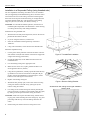
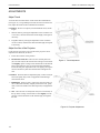
1
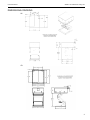
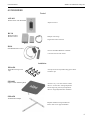
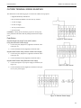
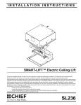
INSTALLATION
INSTRUCTIONS
SMART-LIFT 236 Electric Ceiling Lift
TM
The Model SL-236 Electric Ceiling Lift is a reliable,
heavy-duty video lift mechanism for LCD /DLP projectors
requiring an extended drop from their hidden location.
The ceiling lift is designed for home-theater, conference
room, or school applications.
The SL-236 provides an attractive solution to recess a
projector in the ceiling. The lift is suitable for finished or
suspended ceiling with a finish kit. The concealed bottom
can be finished to match existing ceiling design and color
to conform to room decor.
Plenum Rating requires use of Class II control wiring,
electrically hard wiring the unit, and all open holes in the
housing (except joist tabs) must be sealed using foil tape.
BEFORE YOU BEGIN
• CAUTION: To prevent damage to the ceiling lift, which could affect or void the factory warranty, thoroughly study
all instructions and illustrations before you begin to install or operate the lift. Pay particular attention to the “Important Precautions” on Page 1.
• CAUTION: For smooth and reliable operation, the lift must be installed square and parallel in all dimensions. Avoid
stressing or twisting the lift at any time during installation.
• Because of the size and weight of the lift, Chief Manufacturing recommends that at least two people be available
when installing the lift.
• If you have any questions concerning this installation, contact Chief Manufacturing at 1-800-582-6480.
CHIEF MANUFACTURING INC.
1-800-582-6480 952-894-6280 FAX 952-894-6918
8401 EAGLE CREEK PARKWAY
SAVAGE, MINNESOTA 55378 USA
PART NO. 8820-000008 (Rev. E)
2008 Chief Manufacturing
www.chiefmfg.com
04-08
©
Instruction Manual
SMART-LIFT 236 Electric Ceiling Lifts
IMPORTANT WARNINGS AND CAUTIONS!
• WARNING: This is an electrical device. All electrical installation procedures should be performed by a qualified electrician.
• WARNING: Improper installation can result in serious personal injury! Make sure that the ceiling structural members can support a redundant weight factor five times the total weight of the equipment. If the ceiling can not support
this weight, reinforce the ceiling before installing the lift.
• WARNING: Be aware during the installation that this is a motorized device, and there are pinch points for people and
for electrical wiring.
• WARNING: Be aware of the potential for personal injury or damage to the lift if it is not adequately mounted. The lift
(without a projector) weighs approximately 85 lbs (38.5 kg).
• WARNING: Plenum rating requires the unit to be hard wired through the provided strain relief, use of Class II control
wiring, and all open holes in housing (except joist tabs) must be sealed using foil tape.
• WARNING: Electrical outlets must be installed by a qualified electrician. Follow all electrical codes.
• CAUTION: Test the lift for shipping damage. See “PRETEST THE LIFT BEFORE INSTALLING” on page 6.
• CAUTION: For smooth and reliable operation, the lift must be installed square and parallel in all dimensions. Avoid stressing or twisting the lift at any time during installation.
• CAUTION: Changes or modifications not approved by Chief Manufacturing could void user’s warranty.
•
CAUTION: Improper weight distribution could lead to equipment damage. Make certain projector weight is centered on cradle when mounted.
TOOLS REQUIRED FOR INSTALLATION
• Phillips screwdrivers, No. 1 and No. 2
• Electric drill and bit set
• Pliers (heavy-duty)
• Electrical wire cutter/stripper
• If suspended from threaded rods: Socket set with extension and open wrenches
NOTE: Other tools may be required depending on the
method of installing the lift in the ceiling.
1
Instruction Manual
SMART-LIFT 236 Electric Ceiling Lifts
CONTENTS
DIMENSIONAL DRAWING ...................................................................
SPECIFICATIONS .................................................................................
ACCESSORIES .....................................................................................
PRETEST THE LIFT BEFORE INSTALLING ........................................
PREPARE THE CEILING OPENING AND
INSTALL THE LIFT ...............................................................................
General Guidelines ...................................................................
Installation in a Suspended Ceiling (using threaded rods) .......
Installation in a Wood Framework (or Side-Mounted to Joists)
3
4
5
6
7
7
8
9
CONNECT POWER TO THE LIFT ........................................................ 10
Non Plenum Rated Installation ................................................. 10
Plenum Rated Installation ......................................................... 10
(OPTIONAL) INSTALLING WIRING COVER..........................................11
INSTALL THE PROJECTOR ON THE LIFT .......................................... 12
Install and Route Cables ........................................................... 12
ADJUSTMENTS .................................................................................... 13
Adjust Travel ............................................................................. 13
Adjust the Aim of the Projector ................................................. 13
OUTSIDE TERMINAL WIRING EXAMPLES ......................................... 14
Push Button .............................................................................. 14
Supplied SPST Switch Using Internal 24VAC Power Supply ... 14
Supplied SPST Switch Using Internal 12VDC Power Supply ... 14
Supplied SPST Switch Using External Power Supply .............. 14
SPDT Switch or 2 Dry Contact Closures, Momentary or
Latching .................................................................................... 15
Internal 12VDC Power Supply 2.5A Maximum ......................... 15
Internal 24VAC Power Supply, 1.2A Max ................................. 15
Internal Dry Contact Closures.................................................... 15
Service Position ........................................................................ 15
INSIDE TERMINAL WIRING EXAMPLES ............................................. 16
Push Button .............................................................................. 16
Supplied SPST Switch Using Internal 24VAC Power Supply ... 16
Supplied SPST Switch Using Internal 12VDC Power Supply ... 16
Supplied SPST Switch Using External Power Supply .............. 16
SPDT Switch or 2 Dry Contact Closures, Momentary or
Latching .................................................................................... 17
Internal 12VDC Power Supply 1.2 A Maximum ........................ 17
Internal 24VAC Power Supply, 2.5 A Maximum ....................... 17
Internal Dry Contact Closures ................................................... 17
Low Voltage Sensing: ............................................................... 17
Service position.......................................................................... 17
INTERIOR TERMINAL DESIGNATIONS .............................................. 18
EXTERIOR TERMINAL DESIGNATIONS ............................................. 20
TROUBLESHOOTING .......................................................................... 22
2
Instruction Manual
SMART-LIFT 236 Electric Ceiling Lifts
DIMENSIONAL DRAWING
SP
FD
3
Instruction Manual
SMART-LIFT 236 Electric Ceiling Lifts
SPECIFICATIONS
OVERALL DIMENSIONS CLOSED (HxWxD):
FD: 11.06 x 26.35 x 28.85
SP: 12.25 x 25.12 x 28.31
MAXIMUM AVAILABLE SPACE FOR
PROJECTOR AND EQUIPMENT (HxWxD):
9.25 x 20.50 x 22.75
CLOSURE PANEL SIZE (WxD):
23.87 x 23.87
RECOMMENDED CEILING OPENING SIZE (WxD)*:
25.50 x 28.00
AVAILABLE TRAVEL DISTANCE:
36.00"
ROLL ADJUSTMENT:
2°
PITCH ADJUSTMENT:
15°
YAW ADJUSTMENT:
10°
INTERNAL HEIGHT ADJUSTMENT:
2.00"
INTERNAL FORE/AFT ADJUSTMENT:
3.00" (1/2" INCREMENTS)
INTERNAL LEFT/RIGHT ADJUSTMENT:
2.00" (1/2" INCREMENTS)
COLOR:
WHITE
MAXIMUM WEIGHT CAPACITY:
35#
NET WEIGHT:
85#
OUTPUT RELAYS:
1.0 AMP@30VDC
0.5 AMP@125VAC
0.3 AMP@60VDC
INTERNAL POWER SUPPLY:
12VDC, 2.5A MAX
24VAC, 1.2A MAX
CURRENT DRAW:
.75A
FUSE:
4A, BUSSMAN TYPE GDB
*A NOTCH MAY BE REQUIRED TOWARD THE REAR OF THE OPENING TO CLEAR THE TERMINAL BLOCK. SEE
DIMENSIONAL DRAWINGS.
4
Instruction Manual
SMART-LIFT 236 Electric Ceiling Lifts
ACCESSORIES
Control
ASP-401
Rocker Switch with Wall Plate
Simple lift control.
RC-10
Radio Frequency
Remote Control
Multiple code settings.
Single button control of the lift.
IR-10
Infra-Red Remote Control
Discrete UP/DOWN/SERVICE commands.
Used with most universal remotes.
Installation
SMA-620
Suspended Ceiling Track
Clip
Securely attaches the suspended ceiling grid to the lift.
Includes 8 clips.
SMA-601
Single Column Mounting Plate
Attaches to any 1 1/2” NPT extension column.
Allows 3” fore/aft and 3” left/right adjustment.
Permits slight roll, pitch and yaw adjustment.
Allows 2” height adjustment after installation.
SMA-650
Threaded Rod Adapter
Simplifies installation using threaded rods.
Allows cable use for support/installation.
5
Instruction Manual
SMART-LIFT 236 Electric Ceiling Lifts
PRETEST THE LIFT BEFORE INSTALLING
IMPORTANT: Before mounting the lift in the ceiling, perform
the following test to be sure that it operates properly and has
not been damaged during shipping.
1.
Attach supports (not supplied) to the top of the lift (see
Figure 1).
2.
Suspend the lift at least 3 1/2 feet high from a suitable structure
[i.e. saw horses, ladders, or tables (see Figure 2)].
NOTE: The supplied momentary push button and power cord can
be used to pre-test the lift (see and “OUTSIDE TERMINAL
WIRING EXAMPLES” on page 13).
3.
Cycle the lift through the “show” and “service” positions, making sure the unit operates smoothly.
Figure 1. Support the Unit
Figure 2. Suspend the Unit
6
Instruction Manual
SMART-LIFT 236 Electric Ceiling Lifts
PREPARE THE CEILING OPENING AND INSTALL THE LIFT
Because of the wide variety of possible mounting situations, Chief Manufacturing can only provide general guidelines
for preparing the location where the Smart-Lift will be installed. Study the following information carefully, and adapt it as
necessary to fit your specific installation.
WARNING: Be especially aware of the weight of the lift, and the potential for personal injury or of damage to
the lift if it is not adequately mounted. The lift (without a projector) weighs approximately 85 lbs (38.5 kg).
The “General Guidelines” below, and the information on the following pages, covers the most common mounting situations:
• Suspend the lift from threaded rods that secure to the structural cross brace.
• Side-mount the lift to the ceiling joists or secure the lift to a wood framework mounting to the joists.
General Guidelines
• Carefully determine the position of the ceiling opening and its distance from, and orientation toward, the screen.
• If possible, prepare an area above the ceiling that is sufficiently larger than the lift, Leaving at least an 8” access to
all sides and above the top of the lift for any future maintenance or repair.
WARNING: Improper installation can result in serious personal injury! To avoid such injury, make sure
that the ceiling structural members can support a redundant weight factor five times the total weight of the
equipment you intend to support overhead. If they cannot, the ceiling must be reinforced before you
install the lift.
WARNING: Improper installation can result in serious injury! Plenum rated installations require electrically hard wiring the unit through the provided strain relief, the use of Class 2 control wiring, and all open
holes in the housing (except joist tabs) must be sealed using foil tape. You must adhere to all local codes.
CAUTION: For smooth and reliable operation, the lift must be installed square and parallel in all dimensions.
Avoid stressing the lift at any time during installation.
7
Instruction Manual
SMART-LIFT 236 Electric Ceiling Lifts
Installation in a Suspended Ceiling (using threaded rods)
You can suspend the lift housing from three 3/8-in.-dia. threaded
rods (not supplied by Chief Manufacturing) First, secure the rods to
a structural cross brace in the ceiling. Insert the rods through the
three holes on the top side of the lift housing, or through the holes
of optional brackets SMA-651, and secure them to the housing
using two jam nuts (one inside, one outside). See Fig. 3.
CAUTION: For smooth and reliable operation, the lift must be
installed square and parallel in all dimensions. Avoid stressing
or twisting the lift at any time during installation.
Install the lift using threaded rods:
1.
With the lift in the fully retracted position, remove the closure
panel from the bottom of the lift.
2.
If you are using the SMA-651, install it now.
3.
Insert the 3 threaded rods through the top of the lift or
SMA-651.
4.
Using nuts and washers, secure the lift to the threaded rods.
Finish the suspended ceiling:
1.
Cut the grid to fit the perimeter of the lift and insert it into the
side channel of lift (the side channel of the lift will support the
weight of the ceiling grid and tiles).
2.
If using the SMA-620, see the SMA-620 instructions and
install them now.
3.
Cut surrounding ceiling tile to appropriate size.
4.
Make sure the unit is level, square, parallel and there is no
stress applied to the box (chassis).
5.
Using the test push button, carefully operate the lift all the way
up and down to be sure the clearances are adequate. Be prepared to stop the lift immediately if the lift begins to sound
labored or one side begins to travel slower.
6.
Replace surrounding ceiling tile.
7.
With lift at least partway open, remove four screws securing
ceiling tile retainer on bottom of tray (see Figure 4) and
remove ceiling tile retainer.
8.
Cut ceiling tile to fit inside ceiling tile retainer [include grid
pieces if necessary (see Figure 5)] and install ceiling tile (grid)
by sliding it into the open end of the ceiling tile retainer.
Figure 3. Threaded Rod Installation
Figure 4. Remove Ceiling Retainer
SL236 shown with ceiling tile and grid installed in
bottom panel
CAUTION: Make sure all parts assemble easily, without distorting any parts, when installing tile in the ceiling tray. Any parts
protruding from the tray will cause damage when the unit
closes.
9.
Install ceiling tile retainer and secure using four screws.
Figure 5. Grid Intersection
8
Instruction Manual
SMART-LIFT 236 Electric Ceiling Lifts
11. After installing the lift, use the test push button to carefully
operate the lift all the way up and down to be sure the clearances are adequate. Be prepared to stop the lift immediately
if the lift begins to sound labored or if one side or the other side
begins to travel slower.
12. To maintain plenum rating, seal any openings in the lift housing (except joist tabs) using foil tape.
Installation in a Wood Framework (or Side-Mounted to Joists)
A suitable framework must be constructed to support the lift in the
ceiling. Refer to for dimensions of the lift. The lift housing has
mounting tabs to assist in side-mounting the lift to the ceiling joists
or otherwise securing it to a wood framework.
The ideal lift installation time is after the sheetrock has been
installed, but before the sheetrock has been mudded or finished.
1.
Remove the closure panel from the bottom of the lift to gain
access to the front and back mounting holes.
CAUTION: For smooth and reliable operation, the lift must be
installed square and parallel in all dimensions. Avoid stressing
the lift at any time during installation.
2.
Position the lift in the desired location, making sure the unit is
level, square, parallel and there is no stress applied to the box
(chassis).
3.
Secure the lift to the joists or wood framework. Drive at least
six 1/4 x1-1/4-in. lag screws through the mounting tabs around
the inside of the lift housing and mounting holes across the
back of the lift. There are 8 tab locations, three in each side and
two in one end, and 3 mounting hole locations across the back
of the lift (see Figure 6 and Figure 7). The lift requires support
on two opposing sides only.
4.
5.
Figure 6. Mounting Locations
After installing the lift, use the test push button to carefully
1/4 Dia. Lag Screw
operate the lift all the way up and down to be sure the clearances are adequate. Be prepared to stop the lift immediately
if the lift begins to sound labored or if one side or the other side
begins to travel slower.
Alternate 1/4 Dia.
Bolt Thru
To maintain plenum rating, seal any openings in the lift housing (except joist tabs) using foil tape.
The bottom of the lift may be painted or textured as necessary to
match the ceiling.
Joist
Lift Housing
Sheetrock
NOTE: Bead flange setback allows
finish compound to hide
lift housing seam.
Bead Flange
Finish Ceiling
Compound
Figure 7. Mounting Method
9
Instruction Manual
SMART-LIFT 236 Electric Ceiling Lifts
CONNECT POWER TO THE LIFT
WARNING: Plenum rating requires hard wiring and use of
Class II control wiring. Follow all local building and electrical
codes.
NOTE: If the lift is cycled up and down repeatedly, the thermal
overload on the motor may stop operation. Operation will
resume when the thermal overload cools and resets (5 to 15
minutes).
Non Plenum Rated Installation
1.
Terminate Power Leads
Electrical Junction Box
Inside Smartlift
Plug the lift’s power cord (supplied) into an electrical outlet.
Plenum Rated Installation
WARNING: A licensed electrician should
disconnect and terminate the leads to the
power cord receptacle and, using the
access holes provided for a strain relief,
hard wire the unit to a power source.
WARNING: Failure to disconnect and terminate power leads
properly may result in equipment damage or personal injury.
1.
Disconnect and terminate the electrical leads from the power
cord receptacle at the interior junction box (see Figure 8).
2.
Remove the electrical knockout and install the strain relief
(provided).
3.
Hard wire the unit to a 110V 60 Hz or 230V 50 Hz (as appropriate) 15-amp power source.
4.
Replace interior outlet in a horizontal position as noted on the
stickers found on the outlet cover plate.
10
Figure 8. Disconnect and Terminate
Power Cord Leads
(Optional) Installing Wiring Cover
5.
Place switch hole cover behind the cover plate and attach
with two Phillips head screws from the kit.
An optional wiring cover may be installed to further protect
wiring from mechanical damage.
6.
Replace cover plate and attach using two Phillips head
screws removed in Step 4.
WARNING: Make sure that power to SL-236 is OFF before
proceeding!
7.
Remove three Phillips head screws from SL-236.
8.
Place motor wiring cover in place and attach with three
Phillips head screws removed in Step 7.
9.
Remove three Phillips head screws from SL-236.
1.
Remove the control harness. (See Figure 9)
2.
Using four Phillips head screws, attach cover (included in
kit) over hole created in Step 1.
3.
Make control connections directly to the control box. (See
Inside Terminal Wiring Examples sections.)
4.
Remove and save two Phillips head screws from opposite
corners of cover plate, and remove cover plate from
SL-236. (See Figure 9)
10. Place control wiring cover in place and attach with three
Phillips head screws removed in Step 9.
NOTE: Some components not shown for clarity.)
x4
Control
Harness
2
Cover
Plate
5
1
x2
Switch Hole
Cover
Motor Wiring
Cover
Control Wiring
Cover
7
4
x2
x3
8
6
9
x3
10
x3
x2
Figure 9
11
Instruction Manual
SMART-LIFT 236 Electric Ceiling Lifts
INSTALL THE PROJECTOR ON THE LIFT
CAUTION: Improper projector weight distribution could lead to
equipment damage. Make certain projector weight is centered
on cradle when mounted.
1.
Install the SLB bracket on the projector (see the SLB manual
for details).
2.
Remove the yaw adjustment bracket from the lift (see
Figure 9).
3.
Place the yaw adjustment bracket over the studs on the SLB as
shown, selecting the set of holes that best centers the weight of
the projector.
4.
Install tapered thumb nuts (minimum 3), making sure the
tapered end is toward the projector.
5.
Reinstall the yaw adjustment bracket with projector attached.
NOTE: If desired, the projector can be set directly on the bottom
plate of the lift, not secured by the bracket. The bracket may be
removed for esthetic purpose by removing four roll/height
adjustment nuts (see ADJUSTMENTS).
Install and Route Cables
Figure 9. Install Projector
CAUTION: Do not attach cables to lower lifting arms or sides of
cradle. This may result in damage when lift retracts.
NOTE: Two routing paths are provided, one on each side, to separate electrical and video cables.
1.
Lower lift to service position.
2.
Route and secure all electrical and video cables using ties and
eyelets provided (see Figure 10), leaving some slack between
securing points.
3.
Plug the projector’s power cord into one of the two outlets
inside the lift. One outlet is switched and the other is continuously live. The switched outlet is marked with an “S”.
Figure 10. Cable Routing Example
12
Instruction Manual
SMART-LIFT 236 Electric Ceiling Lifts
ADJUSTMENTS
Adjust Travel
An access hole is located in the corner below the terminal block
(see Figure 11). Using a Phillips screwdriver inserted in the access
hole, adjust the stroke of the lift mechanism as follows:
CAUTION: Do not over adjust (exceed maximum travel) stroke
length.
1.
Shorten stroke by turning the adjustment screw clockwise one
or two turns, check for the desired stroke length, and repeat as
necessary.
2.
Lengthen stroke by turning the adjustment screw clockwise
one or two turns, check for the desired stroke length, and repeat
as necessary.
Adjust the Aim of the Projector
Center the lens (see Figure 12). The aim of the projector can be
adjusted in all directions, as shown:
1.
Lower the lift to the 'show' position.
2.
Pitch and forward/Aft. There are four 10-24 Nylock nuts
(two on each side) on the outside of the carriage. Loosen these
nuts slightly, tip the carriage in the slotted holes to the desired
angle, and tighten the nuts. For forward and aft adjustment,
loosen the four pitch adjustment nuts. Lift slightly, moving forward or aft until tray falls into desired notch and tighten the
nuts.
Figure 11. Travel Adjustment
CAUTION: Each side must be adjusted equally. Failure to adjust
each side equally may result in equipment and lift damage
when the lift closes.
3. Roll/Height. There are four 1/4-20 nuts at the rear inside corners of the cradle assembly. Slightly loosen these nuts, gently
raise or lower the cradle to the desired position, and tighten the
nuts.
4. Yaw. There are four 10-24 Nylock nuts (two on each side) on
the top of the carriage. Loosen these screws slightly, turn the
carriage in the slotted holes to the desired angle, and tighten
the nuts.
Figure 12. Projector Adjustment
13
Instruction Manual
SMART-LIFT 236 Electric Ceiling Lifts
OUTSIDE TERMINAL WIRING EXAMPLES
The information on the following pages cover the most common wiring options:
• Supplied Momentary Push Button
• Discrete Extend and Retract for switch or dry contacts
• 12 Volt out supply
• 24 Volt out supply
• Two dry contact closures
• Service Extend
CAUTION: Closing the unit while the projector is running may
cause premature bulb failure and may damage both the lift and projector.
Push Button
Figure 13. 24VAC Internal
Supplied Single Pole Single Throw (SPST) Switch
Using Internal 24VAC Power Supply
a. Connect the green jumper wire (supplied) to terminals 1 & 5
(see Figure 13).
b. Connect the SPST switch (supplied) to terminals 2 & 6.
Supplied SPST Switch Using Internal 12VDC Power Supply
a. Connect the green jumper wire (supplied) to terminals 5 & 9
(see Figure 14).
b. Connect the SPST switch (supplied) to terminals 6 & 10.
Supplied SPST Switch Using External Power Supply
a. Connect the negative of your power supply to terminal 5 (see
Figure 15).
Figure 14. 12DC Internal
b. Connect the SPST switch (supplied) to terminal 6 & the positive of your power supply.
Figure 15. External Power Supply
14
Instruction Manual
SMART-LIFT 236 Electric Ceiling Lifts
Single Pole Double Throw (SPDT) Switch or
2 Dry Contact Closures, Momentary or Latching.
These terminals can be used with any latching contacts, momentary
contacts, or a wall switch.
NOTE: The connection between the ground (#9) and any other terminal connection must be broken (open) before completing the
next circuit..
a. Connect the common wire from your switch to
terminal 9 (see Figure 16).
b. Connect the 'up' wire from your switch to terminal 3.
c. Connect the 'down' wire from your switch to terminal 4.
Internal 12VDC Power Supply 2.5A Maximum
(+) = Terminal 10
(-) = Terminal 9
NOTE: Non regulated, open circuit voltage may exceed 18V.
Internal 24VAC power supply, 1.2 A max
(+) = Terminal 1
(-) = Terminal 2
Internal dry contact closures:
Common = Terminal 12
Closed when lift reaches show position = 14
Closed when lift is fully closed = 13
Service Position
Momentary contact between terminals 9 & 11 will lower the
lift to the service position.
NOTE: To stop the lift before it reaches the service position, make
a momentary contact between terminals 3 & 9.
.
15
Figure 16. Dry Contacts
Instruction Manual
SMART-LIFT 236 Electric Ceiling Lifts
INSIDE TERMINAL WIRING EXAMPLES
The information on the following pages cover the most common wiring options:
• Supplied Momentary Push Button
• Discrete Extend and Retract for Switch or Dry Contacts
• 12 Volt out supply
• 24 Volt out supply
• Two dry contact closures
• Voltage Sensing
• Service Extend
CAUTION: Closing the unit while the projector is running may
cause premature bulb failure and may damage both the lift and projector.
Push Button
Supplied Single Pole Single Throw (SPST) Switch Using
Internal 24VAC Power Supply
Figure 17. 24VAC Internal
a. Connect the green jumper wire (supplied) to terminals 2 & 6
(see Figure 17).
b. Connect the SPST switch (supplied) to terminals 1 & 5.
Supplied SPST Switch Using Internal 12VDC Power Supply
a. Connect the green jumper wire (supplied) to terminals 6 &
10 (see Figure 18).
b. Connect the SPST switch (supplied) to terminals 4 & 5.
Supplied SPST Switch Using External Power Supply.
a. Connect the negative of your power supply to terminal 6 (see
Figure 19).
Figure 18. 12DC Internal
b. Connect the SPST switch (supplied) to terminal 5 & the positive of your power supply.
Figure 19. External Power Supply
16
Instruction Manual
SMART-LIFT 236 Electric Ceiling Lifts
Single Pole DOUBLE Throw (SPDT) Switch or
2 Dry Contact Closures, Momentary or Latching.
a. Connect the common wire from your switch to
terminal 13 (see Figure 20).
b. Connect the 'up' wire from your switch to terminal 12.
c. Connect the 'down' wire from your switch to
terminal 11.
Internal 12VDC Power Supply 2.5A Maximum
(+) = Terminal 4
(-) = Terminal 3
NOTE: Non regulated, open circuit voltage may exceed 18V.
Internal 24VAC Power Supply, 1.2A Maximum
Figure 20. Dry Contacts
(+) = Terminal 1
(-) = Terminal 2
Internal Dry Contact Closures:
Common = Terminal 12
Closed when lift reaches show position = Terminals 16 and 17
Closed when lift is fully closed = Terminals 18 and 19
Low Voltage Sensing:
a. Connect the positive of your power supply to terminal 7.
b. Connect the negative of your power supply to terminal 8.
NOTE: The lift will complete a full cycle even if the supply is
turned off before the lift reaches full extension.
NOTE: When the lift is in the lowered position using this option,
the lift will ignore all other commands until it has completed its
full cycle.
When the power supply is on, the lift will extend. When the
power supply turns off, the lift will retract.
Service position:
Momentary contact between terminals 9 & 10 will lower the
lift to the service position.
NOTE: To stop the lift before it reaches the service position, make
a momentary contact between terminals 11 & 13.
17
Instruction Manual
SMART-LIFT 236 Electric Ceiling Lifts
SMART LIFT INTERIOR BOARD BOX
TERMINAL FUNCTION DEFINITIONS
TERMINAL
NUMBER
FUNCTION
DESCRIPTION
1
24 VOLT AC
24 volt AC output
2
24 VOLT AC
COMMON
24 volt AC common
3
GROUND
Ground
4
12 VOLT DC
12 volt DC
5
EXTEND/
RETRACT
Initiates movement if lift is static, or
stops movement if lift is in motion.
Direction of travel will be opposite
of last direction of travel.
6
7
8
EXTEND/
RETRACT
COMMON
VOLTAGE
SENSOR
VOLTAGE
SENSOR
COMMON
9
SERVICE
EXTEND
10
GROUND
Used in conjunction with
Extend/Retract when using an
external power source to initiate
movement.
When terminal senses voltage, unit
will extend.
When terminal senses cessation of
voltage, unit will retract.
Used in conjunction with Voltage
Sensor when using an external
power source to initiate movement.
Extends unit to maximum limit,
bypassing normal-use travel setting.
Often used for servicing projectors
in ceiling lifts.
WIRING OPTIONS
NOTES
This is an internal power supply for
powering external devices & Remote
Controllers.
Chief Mfg. offers the RC-10 Radio
Frequency Remote Controller which runs
off of this power supply.
This is an internal power supply for
powering external devices &/or used for
initiating specific functions
(Extend/Retract 5 or Voltage Sensor 7).
To Operate using Internal Power
Source
Connect terminals 3 & 6 with
Jumper Wire. Connect
Momentary Switch to terminal 4.
Connect other line of Momentary
Switch to terminal 5.
Function operates on momentary switch
only.
To Operate using External Power
Source
Connect External Power Supply’s
Common to terminal 6. Connect
initiating signal to terminal 5.
NOT TO BE USED AS GROUND FOR
FUNCTION OTHER THAN
EXTEND/RETRACT TERMINAL 5.
Voltage Sensing
Connect positive lead to terminal
7. Connect Ground of switching
device to terminal 8.
Single-Pull/Throw Latching
Switch
Connect terminals 3 & 8 with
Jumper Wire. Connect first
Switch Terminal to terminal 4.
Connect other Switch Terminal to
terminal 7.
Operating range is 5 – 30 Volts AC or DC.
Operating range is 5 – 30 Volts AC or DC.
NOT TO BE USED AS GROUND FOR
FUNCTION OTHER THAN VOLTAGE
SENSOR TERMINAL 7.
Feature not available on all models.
Momentary or Latching contact to
Ground terminals 3, 10, 13, or 20.
If using Latching Switch, be sure to
disengage Switch prior to initiating any
other function.
Ground
18
Instruction Manual
SMART-LIFT 236 Electric Ceiling Lifts
Extends unit to preset travel limit.
11
EXTEND
Customer within a preset maximum
range may adjust travel limits.
Retracts unit to preset travel limit.
19
12
RETRACT
Travel limits may be adjusted by
customer within a preset maximum
range.
13
GROUND
Ground
14
EXTEND
ERROR
Immediately reverses direction of
travel when triggered while unit is
extending.
15
RETRACT
ERROR
16
EXTEND
LIMIT
RELAY
17
EXTEND
LIMIT
RELAY
COMMON
18
RETRACT
LIMIT
RELAY
19
RETRACT
LIMIT
RELAY
COMMON
20
GROUND
If using Latching Switch, be sure to
disengage Switch prior to initiating any
other function.
Immediately reverses direction of
travel when triggered while unit is
retracting.
Momentary or Latching contact to
Ground terminals 3, 10, 13, or 20.
If using Latching Switch, be sure to
disengage Switch prior to initiating any
other function.
Momentary contact to Ground
terminals 3, 10, 13, or 20.
Chief Mfg. offers the SS-10 Pressure
Sensitive Safety Strip to provide this
function.
Please specify how many inches required
spanning entire pinch zone.
The SS-10 must be ordered with the ST-15
Terminals.
Closes set of internal dry contacts
when unit reaches full extension.
AMP@30VDC
RATED FOR 11.0
AMP
@ 24 VOLTS
Closes set of internal dry contacts
when unit reaches full retraction.
AMP@30VDC
RATED FOR 11.0
AMP
@ 24 VOLTS
Ground
0.5 AMP@125VAC
0.3 AMP@60VDC
0.5 AMP@125VAC
0.3 AMP@60VDC
Instruction Manual
SMART-LIFT 236 Electric Ceiling Lifts
SMART LIFT EXTERIOR 14 PIN
TERMINAL FUNCTION DEFINITION
TERMINAL
NUMBER
FUNCTION
DESCRIPTION
1
24 VOLT AC
24 volt AC output
2
24 VOLT AC
COMMON
24 volt AC common
WIRING OPTIONS
This is an internal power supply for
powering external devices & Remote
Controllers.
Chief Mfg. offers the RC-10 Radio
Frequency Remote Controller which runs
off of this power supply.
Retracts unit to preset travel limit.
3
RETRACT
Travel limits may be adjusted by
customer within a preset maximum
range.
If using Latching Switch, be sure to
disengage Switch prior to initiating any
other function.
Momentary or Latching contact to
Ground terminals 9, or 11.
If using Latching Switch, be sure to
disengage Switch prior to initiating any
other function.
Extends unit to preset travel limit.
4
EXTEND
5
EXTEND/
RETRACT
COMMON
Used in conjunction with
Extend/Retract when using an
external power source to initiate
movement.
6
EXTEND/
RETRACT
Initiates movement if lift is static, or
stops movement if lift is in motion.
Direction of travel will be opposite
of last direction of travel.
Customer within a preset maximum
range may adjust travel limits.
RETRACT
ERROR
Immediately reverses direction of
travel when triggered while unit is
retracting.
8
EXTEND
ERROR
Immediately reverses direction of
travel when triggered while unit is
extending.
9
GROUND
Ground
10
12 VOLT DC
12 volt DC
7
Extends unit to maximum limit,
bypassing normal-use travel setting
11
Service Extend
Often used for servicing projectors
in ceiling lifts.
NOTES
To Operate using Internal Power
Source
Connect terminals 9 & 5 with
Jumper Wire. Connect
Momentary Switch to terminal
10. Connect other line of
Momentary Switch to terminal 6.
To Operate using External Power
Source
Connect External Power Supply’s
Common to terminal 5. Connect
initiating signal to terminal 6.
Momentary contact to Ground
terminals 9, or 11.
NOT TO BE USED AS GROUND FOR
FUNCTION OTHER THAN
EXTEND/RETRACT TERMINAL 5.
Function operates on momentary switch
only.
Operating range is 5 – 30 Volts AC or DC.
Chief Mfg. offers the SS-10 Pressure
Sensitive Safety Strip to provide this
function.
Please specify how many inches required
to span entire pinch zone.
The SS-10 must be ordered with the ST-15
Terminals.
This is an internal power supply for
powering external devices &/or used for
initiating specific functions
(Extend/Retract 6).
Feature not available on all models.
Momentary or Latching contacts
to Ground terminals 3, 10, 13, or
20
If using Latching Switch, be sure to
disengage Switch prior to initiating any
other function
20
Instruction Manual
21
SMART-LIFT 236 Electric Ceiling Lifts
12
LIMIT
RELAY
COMMON
13
RETRACT
LIMIT
RELAY
14
EXTEND
LIMIT
RELAY
Closes set of internal dry contacts
when unit reaches full retraction.
Closes set of internal dry contacts
when unit reaches full extension.
AMP@30VDC
RATED FOR 11.0
AMP
@ 24 VOLTS
0.5 AMP@125VAC
0.3 AMP@60VDC
Instruction Manual
SMART-LIFT 236 Electric Ceiling Lifts
TROUBLESHOOTING
SYMPTOM
LIFT DOES NOT RESPOND
LIFT WILL NOT LOWER/RAISE
CONTROL BOX CLICKS
MOTOR SILENT
LIFT WILL NOT LOWER/RAISE
CONTROL BOX CLICKS
MOTOR HUMS
PROJECTOR CRADLE / BOTTOM
PANEL LOWER ON ONE SIDE.
PROJECTOR CRADLE / BOTTOM
PANEL SIGNIFICANTLY LOWER ON
ONE SIDE
HOOKS ON LIFTING BRACKET DO
NOT CATCH THE ROLLERS ON THE
PROJECTOR CRADLE.
POSSIBLE CAUSE
12V TRIGGER OPTION BEING USED
NO POWER
FUSE BLOWN
LIMIT SWITCH
FAILED CONTROL BOX
OVERHEATED MOTOR
CORRECTIVE ACTION
NORMAL OPERATION
SEE NOTES ON 'LOW VOLTAGE SENSING' PAGE#16
VERIFY POWER TO LIFT
CHECK FUSE ON CONTROL BOX
CALL CHIEF FOR VERIFICATION
CALL CHIEF FOR VERIFICATION
LET MOTOR COOL FOR 5-15 MINUTES.
FAILED MOTOR
BINDING MECHANISM
CALL CHIEF FOR VERIFICATION
MAKE SURE CABLES ARE ROUTED PROPERLY
SEE 'INSTALL AND ROUTE CABLES' PAGE#11
FAILED MOTOR
FAILED CONTROL BOX
NORMAL OPERATION
LIFTING LINKS OUT OF ADJUSTMENT
CALL CHIEF FOR VERIFICATION
CALL CHIEF FOR VERIFICATION
A DIFFERENCE OF UP TO 3/16" WITHIN THE FINAL 4" OF
TRAVEL IS NORMAL
WHEN THE LIFT IS EXTENDED BEYOND 4", UP TO 3/8"
DIFFERENCE IS NORMAL
CALL CHIEF
LIFTING BRACKET DAMAGED
DAMAGED HINGE ASSEMBLY
CALL CHIEF
CALL CHIEF
LIFTING BRACKET DAMAGED
BINDING MECHANISM
CALL CHIEF
MAKE SURE CABLES ARE ROUTED PROPERLY
SEE 'INSTALL AND ROUTE CABLES' PAGE#11
LIFTING LINKS OUT OF ADJUSTMENT
CALL CHIEF
LIFTING BRACKET DAMAGED
DAMAGED HINGE ASSEMBLY
CALL CHIEF
CALL CHIEF
22
Instruction Manual
SMART-LIFT 236 Electric Ceiling Lifts
PAGE LEFT BLANK INTENTIONALLY
23