1
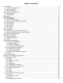
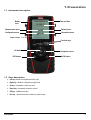
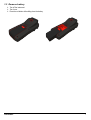
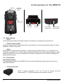
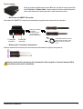
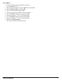
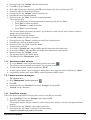
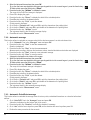
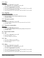
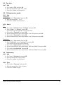
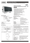
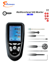
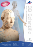
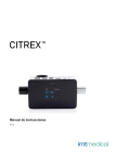
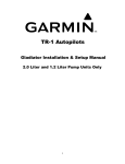
MP 210
Thermo-Anemo-Manometer
Table of contents
1.Presentation.........................................................................................................................................6
1.1. Instrument description..................................................................................................................6
1.2. Keys description...........................................................................................................................6
1.3. Remove battery............................................................................................................................7
2.Connections of the MP210...................................................................................................................8
2.1. Main features...............................................................................................................................8
2.2. Connections.................................................................................................................................8
3.Information.........................................................................................................................................10
4.Set the instrument..............................................................................................................................11
4.1. Set language..............................................................................................................................11
4.2. Modify date and time..................................................................................................................11
4.3. Activate or deactivate the beep key...........................................................................................11
4.4. Set auto-off.................................................................................................................................11
4.5. Set backlight..............................................................................................................................12
4.6. Set security................................................................................................................................12
4.7. Set code.....................................................................................................................................12
4.8. Set printing.................................................................................................................................12
5.Set the probes....................................................................................................................................13
5.1. Use of the wire probes and modules.........................................................................................13
5.2. Special precautions for air velocity probes................................................................................13
5.3. Use of wireless probes...............................................................................................................14
6.Channel configuration........................................................................................................................15
6.1. Pressure module........................................................................................................................15
6.2. Vanes and hot wire....................................................................................................................16
6.3. Delta T........................................................................................................................................17
7.Start and record datasets...................................................................................................................18
7.1. Start and record datasets..........................................................................................................18
7.1.1 Manual dataset....................................................................................................................18
7.1.2 Automatic dataset................................................................................................................18
7.1.3 View the recorded datasets.................................................................................................19
7.2. Launch and save averages........................................................................................................19
7.2.1 Point/Point average.............................................................................................................19
7.2.2 Automatic average...............................................................................................................20
7.2.3 Automatic Point/Point average............................................................................................20
7.3. COmax.......................................................................................................................................21
7.4. Hold-Min./Max............................................................................................................................21
8.Setting of measurement parameters..................................................................................................22
8.1. Pressure module........................................................................................................................22
8.1.1 Unit.......................................................................................................................................22
8.1.2 Type.....................................................................................................................................22
8.1.3 Normative value...................................................................................................................22
8.1.4 Alarm....................................................................................................................................23
8.1.5 Integration............................................................................................................................23
8.1.6 Atmospheric pressure..........................................................................................................23
8.1.7 Temperature compensation.................................................................................................23
8.2. Thermocouple module...............................................................................................................23
8.2.1 Unit.......................................................................................................................................23
8.2.2 Type.....................................................................................................................................23
8.2.3 Alarm....................................................................................................................................23
8.3. Vane probe and hotwire probe...................................................................................................24
8.3.1 Unit.......................................................................................................................................24
8.3.2 Normative value...................................................................................................................24
8.3.3 Alarm....................................................................................................................................24
8.3.4 Atmospheric pressure..........................................................................................................24
8.4. Gas leak.....................................................................................................................................25
8.4.1 Unit.......................................................................................................................................25
8.5. CO/temperature probe...............................................................................................................25
8.5.1 Unit.......................................................................................................................................25
8.5.2 Alarm....................................................................................................................................25
8.6. Tachometry.................................................................................................................................25
8.6.1 Unit.......................................................................................................................................25
8.6.2 Type.....................................................................................................................................25
1. Presentation
1.1 Instrument description
Battery
level
Date and time
Measurement menu
Dataset menu
Configuration menu
Information menu
Home screen
Function keys
OK button
ESC button
Navigation arrows
On/Off button
1.2 Keys description
➢ Left key: allows to navigate from left to right
➢ Right key : allows to navigate from right to left
➢ Up key : increments a value or a level
➢ Down key : decrements a value or a level
➢ OK key : validates an action
➢ Esc key : cancels the action or backs to previous step
Presentation
6
1.3 Remove battery
➢ Turn off the instrument.
➢ Turn it over.
➢ Press the red button while sliding down the battery.
Presentation
7
2. Connections of the MP210
Module
Location to
remove the
module
Probe handle
C2 mini-DIN
connection
C1 mini-DIN
connection
USB connection
+ power supply
Light indicator for
battery charging
Battery
2.1 Main features
• Screen
120x160 pixels graphic display and backlight. Display of 6 measurements, 3 simultaneously. Size 50x67 mm.
• Printer (available as option)
The paper of the instrument is a thermal paper with a 10-year guarantee. It has an easy replacement system of the paper
(Easyload). In addition, printing is fast.
• Battery
Rechargeable Li-ion battery inside the instrument, 16 h battery-life with a pressure module or 14 h a hotwire probe. The
instrument is supplied with a 5 V, 1 A power adapter to load the internal battery. The current loading is indicated by a battery
symbol on the top left of the screen. The orange led on the bottom of the instrument is also on until the full loading of the
battery (the led turns green).
2.2 Connections
Interchangeable modules
The interchangeable modules have the SMART-2014 system and are automatically recognized once the connection is
made on the instrument.
•
Thermocouple module:
Allows to measure temperature on Tc1, Tc2, Tc3 and Tc4 channels with wired
thermocouples K, J, T or S probes ended with a male miniature connector
8
Connections of the MP210
Pressure module :
Allows to measure the differential pressure ΔP and to calculate air velocity and airflow
with a Pitot tube or Debimo blades. It also measures the thermocouple temperature
with a wired thermocouple probe ended with a male miniature connector.
•
Wire probes with SMART-2014 system
Wire probes with SMART 2014 system are automatically recognized when connected to the instrument.
Probes are connected
on min-DIN
connectors C1 and
/ or C2 (excepted
thermocouple probes)
C2 mini-DIN
connection
•
C1 mini-DIN
connection
Overmolded mini-DIN connector
with foolproofing system. Cable
length lg. 450 mm, extension
2.4 m.
Wireless probe / instrument communication
Wireless communication between probe and instrument with automatic recognition after power-up.
Wireless probes shall be located near the instrument for initial recognition. Connection between HQ210
and wireless probes must be established.
Connections of the MP210
9
3. Information
“Information”
menu allows to view information about the instrument, probes and module connected to the “Wireless
probe”, “Mini-DIN 1”, “Mini-DIN 2” or “Module” connections. To enter in this menu from home screen, select the
“Information” menu with the arrow keys then press OK.
Available information for probes and module is :
• Type of probes and module
• Date of the last calibration or adjustment
• Serial number
• Firmware version
• Measuring range
Available information for the instrument is :
• Type of instrument
• Serial number
• Firmware version
➢ The function key “Measurement” allows to access directly to the “Measurement” menu.
10
Information
4. Set the instrument
The instrument is on.
➢ With the arrow keys, go to “Configuration” menu.
➢ Press OK..
4.1 Set language
“Configuration” screen is displayed.
➢ Select “Language” with the arrow keys then press OK.
Available languages are displayed.
➢ Press Up and Down arrows to select the required language : FRA, ENG...
➢ Press OK.
4.2 Modify date and time
➢ “Configuration” screen is displayed.
➢ Select “Date/time” with the arrow keys then press OK.
The screen of configuration for date and time is displayed.
➢ Go to the “Date” format with arrow keys then press OK.
➢ Select : DD/MM/YYYY, MM/DD/YYYY or YYYY/MM/DD then press OK.
➢ Go to the day then press OK.
➢ With Up and Down keys, set the first digit of the day then go to the following one with right arrow.
➢ Press OK to validate.
Perform the same procedure to set the month and year.
➢ Go the “Time” format with arrow keys then press OK.
➢ Select the time format : “12H” or “4H” then press OK.
If “12H” is selected, it is possible to choose between “AM” for ante meridiem or “PM” for post meridiem.
➢ Press OK, select “AM” or “PM” then press OK to validate.
➢ Go the time then press OK.
➢ With Up and Down keys set the first digit of the day then go to the following one with right arrow.
➢ Press OK to validate.
Perform the same procedure to set minutes and seconds.
➢ Press function key “Validate” to leave the screen and to save modifications or press Esc to cancel.
4.3 Activate or deactivate the beep key
“Configuration” screen is displayed.
➢ Select “Key beep” with arrow keys.
➢ Press OK to activate or deactivate the beep key.
The box is ticked if the beep is activated and unticked when the beep is deactivated.
4.4 Set auto-off
The auto-off function turns off the instrument after a moment of unused.
It is possible to set the auto-off of the instrument at 15 / 30 / 45 / 60 / 75 / 90 / 105 or 120 minutes or to deactivate it.
“Configuration” screen is displayed.
➢ Select “Auto-off” with arrow keys then press OK.
➢ Select the required duration or OFF to deactivate it with Up and Down keys.
➢ Press OK to validate.
Set the instrument
11
4.5 Set backlight
“Configuration” screen is displayed.
➢ Select “Backlight” with arrow keys then press OK.
➢ Select the backlight level between 1 and 9 or “Auto” with Up and Down keys.
➢ Press OK to validate.
4.6 Set security
This part allows to activate or deactivate a security code. This code will be asked when starting the instrument.
“Configuration” screen is displayed.
➢ Select “Security” with arrow keys.
➢ Press OK to activate or deactivated the security.
If the security is activated, please create a security code.
4.7 Set code
If the security is activated, the selected code will be asked when starting the instrument.
“Configuration” screen is displayed and the security is activated.
➢ Go to “Code” then press OK.
➢ With arrow keys, set each digit then press OK when the last digit is set.
Modifications are validated, the instrument backs to “Configuration” screen.
4.8 Set printing
“Configuration” screen is displayed.
➢ Select “Printing” with arrow keys then press OK.
➢ Go to “Format” then press OK.
➢ Select the ticket format : long or short then press OK.
Long ticket format : prints the measurement results + header (operator name, date and time of the intervention,
type of instrument and its serial number)
Short ticket format : prints only the measurement results and the serial number of the instrument
➢ Go to “Logo” then press OK to activate or deactivate it.
The box is ticked when the logo is activated and unticked when the logo is deactivated.
➢ Go to “Operator” to enter an operator name then press OK.
Keypad is displayed on the bottom of the screen.
➢ Select the letters with arrow keys then press OK.
To go from the lower case keypad to the upper case keypad then to the numeric keypad : press the function key :
To delete a letter press the function key “Delete”.
➢ Press the function key “Validate” to validate the name.
➢ Go to “Header 1” to enter the header name then press OK.
Keypad is displayed on the bottom of the screen.
➢ Select the letters with arrow keys then press OK.
➢ Press the function key “Validate” to validate the header 1.
➢ Perform the same procedure to enter a name for the “Header 2”, “Header 3” and “Header 4”.
➢ Press ESC to back to the “Configuration” screen and to validate the modifications.
12
Set the instrument
5. Set the probes
5.1 Use of the wire probes and modules
•
Connect a probe
➢ Connect the mini-DIN cable on the mini-DIN connection of the probe.
➢ Connect the mini-DIN cable with the probe on the instrument.
A beep indicates that the operation has been correctly performed.
Arrow in front of the
user
Arrow in front
of the user
Probe connection
Instrument connection
➢ Go to “Measurement” menu from the home screen.
➢ Press OK.
Measurement are displayed.
5.2 Special precautions for air velocity probes
Sensitive element (velocity)
Sensitive element
(temperature)
Airflow direction
Protective tube of the
sensitive element (1)
Bottom of the telescopic probe
landmark
Bottom of the standard probe
Before any use of the device with an air velocity probe, please lower the protective tube (1) of the
sensitive element (except vane probe).
Always use the standard air velocity probe with the red point in front of the flow.
Always use the telescopic probe with the white point in front of the flow.
Set the probes
13
5.3
•
Use of wireless probes
Add a wireless probe
With arrow keys, go to
“Information” menu
then press OK.
In “Information” menu go to
“Wireless probe” then press
OK.
On the bottom of the
screen press the
function key “Create”.
The probe information is displayed With
the function key “Meas.” It is possible
to back to the measurement screen. It is
also possible to delete the wireless
probe pressing the function key
“Delete”.
Turn on the wireless
probe and keep it press
until the light blinks
Pairing is in progress
OR
With arrow keys, go to
“Measurements”
menu then press OK.
The probe information is
displayed With the function key
“Meas.” It is possible to back to
the measurement screen. It is
also possible to delete the
wireless probe pressing the
function key “Delete”.
14
In “Measurement” menu,
press the function key
“Channels”.
Pairing is in progress
Press the function key
“Probes”.
Turn on the wireless probe and
keep it press until the light
blinks
With the arrow keys, select
“Add wireless probe...”
then press OK.
On the bottom of the screen
press the function key
“Create”.
Set the probes
6. Channel configuration
The channel configuration allows to modify the displaying of the measured parameters.
The instrument is on.
➢ With the arrow keys, go to “Measurement”.
➢ Press OK.
➢ Press the function key “Channels”.
The different functions of the probe are displayed.
IIt is possible from the “Channels” menu to add or delete some measurements.
➢ Press the function key “Delete” in order to delete the selected measurement.
➢ Press the function key “Add” to display the selected measurement.
➢ Press “Add” to add a measurement on the screen (the default measurement displayed on the screen are the
primary measurements).
It is possible from the “Channels” menu to choose the displaying order of the measurement on the screen.
➢ With arrow keys, select the measurement to modify and press OK.
➢ Go to the line “Channel num.” then press OK.
Select the channel number and press OK.
6.1 Pressure module
Airflow:
In the “channels” menu :
➢ Select with arrow key the sub-menu “Airflow” then press OK.
➢ Select “Channel num.” and press OK.
➢ Select a channel number and press OK.
➢ Go to the line “Type” then press OK.
➢ Select the required type : “Rect”, “Circ” or “K factor” and press OK*.
➢ If the type is Rect or Circ :
• Go to “Rect” or “Circ”, press OK, select its size then press OK to validate.
• Go to the line “Areas” then press OK.
It is possible to change units and size.
• Select “Unit” with the arrow keys then press OK. Select mm or in and press OK.
• To modify areas, select with arrow keys “Rect.” or “Circ.” and press OK.
• Select the size to modify in the list and press OK.
• Set the size with arrow keys between 1 and 2500 mm then press OK.
➢ For a K factor : go to “K factor”, press OK, select the K factor then press OK to validate.
➢ If the airflow is calculated with a pressure module, then go to “d/p elem.” to select the differential pressure
element. Press OK then select the element between “Pitot L” (coefficient : 1.0015), “Pitot S” (coefficient : 0.84),
“Débimo” (coefficient : 0.8165) and “Other”. If “Other” is selected, then enter its differential pressure coefficient
between 0 and 9.9999.
➢ Go to the line “K2 fact.” and press OK to select or unselect the K2 factor.
*For a hotwire probe, K factor is not available. It is possible to select “Cone” in addition to “Rect” and “Circ” :
➢ To select “Cone”, go to the line “Cone” then press OK.
• Select the type of cone : K35, K75, K120 or K150 and press OK.
• Press “Measures” to display the measurements.
Channel configuration
15
*For a Ø100 mm vane probe, K factor is not available . It is possible to select “Cone” in addition to “Rect” and “Circ” :
➢ To select “Cone”, go to the line “Cone” then press OK.
• Select the type of cone : K25 or K85 and press OK.
• Press “Measures” to display the measurements.
Air velocity :
In the “channels” menu :
➢ Select with arrow key the sub-menu “Air velocity” then press OK.
➢ Select “Channel num.” and press OK.
➢ Select a channel number and press OK.
“D/p pressure” and “D/p coeff.” are displayed.
➢ Select with arrow keys “D/p pressure” and press OK.
➢ Select Pitot L, Pitot S, Debimo or Other and press OK.
There is a differential pressure coefficient for differential pressure instrument,
➢ Press Esc to back to “Channel” menu.
6.2 Vanes and hot wire
In the “channels” menu :
➢ Select with arrow key the sub-menu “Airflow” then press OK.
➢ Select “Channel num.” and press OK.
➢ Select a channel number and press OK.
➢ Go to the line “Type” then press OK.
➢ Select the required type : “Rect”, “Circ” or “K factor” and press OK*.
If the type is Rect or Circ :
➢ Go to “Rect” or “Circ”, press OK, select its size then press OK to validate.
➢ Go to the line “Areas” then press OK.
It is possible to change units and size.
➢ Select “Unit” with the arrow keys then press OK. Select mm or in and press OK.
➢ To modify areas, select with arrow keys “Rect.” or “Circ.” and press OK.
➢ Select the size to modify in the list and press OK.
➢ Set the size with arrow keys between 1 and 2500 mm then press OK.
➢ For a K factor : go to “K factor”, press OK, select the K factor then press OK to validate.
➢ If the airflow is calculated with a pressure module, then go to “d/p elem.” to select the differential pressure
element. Press OK then select the element between “Pitot L” (coefficient : 1.0015), “Pitot S” (coefficient : 0.84),
“Débimo” (coefficient : 0.8165) and “Other”. If “Other” is selected, then enter its differential pressure coefficient
between 0 and 9.9999.
➢ Go to the line “K2 fact.” and press OK to select or unselect the K2 factor.
*For a hotwire probe, K factor is not available. It is possible to select “Cone” in addition to “Rect” and “Circ” :
➢ To select “Cone”, go to the line “Cone” then press OK.
• Select the type of cone : K35, K75, K120 or K150 and press OK.
• Press “Measures” to display the measurements.
*For a Ø100 mm vane probe, K factor is not available . It is possible to select “Cone” in addition to “Rect” and “Circ” :
➢ To select “Cone”, go to the line “Cone” then press OK.
• Select the type of cone : K25 or K85 and press OK.
• Press “Measures” to display the measurements.
16
Channel configuration
6.3 Delta T
➢ Connect the thermocouple module then the probes.
In the “Channels” menu :
➢ Select with arrow keys the sub-menu “Delta T” then press OK.
➢ Select “Channel number” and press OK.
➢ Select a channel number and press OK.
➢ Select the channels in which Delta T will be calculated.
➢ Go to “Channel A” with arrow keys and press OK.
➢ Select the channel T1, T2, T3 or T4 and press OK.
➢ Go to “Channel B” with arrow keys and press OK.
➢ Select the channel T1, T2, T3 or T4 and press OK.
➢ Press the key “Measurement”.
The instrument displays the measurements.
Channel configuration
17
7. Start and record datasets
➢
➢
➢
➢
➢
➢
The instrument in on.
Select with arrows keys “Measurement” menu.
Press OK.
Select with arrows keys the measurement in which the dataset will be performed.
Press “Functions” key then select “Dataset” with arrow keys and press OK.
Dataset menu is displayed.
Go to line “Name” with arrow keys and press OK.
A keypad is displayed on the bottom of the screen.
Select the letters with arrow keys then press OK.
To go from the lower case keypad to the upper case keypad then to the numeric keypad : press the function key :
To delete a letter press the function key “Delete”.
Press the function “Validate” to validate the name of the dataset.
➢
➢
➢ A dataset is composed of several dated measuring points. You can choose between an automatic dataset or a
manual dataset.
➢ Go to “Type” with arrow keys then press OK.
➢ Select “Manu.” for manual or “Auto.” for automatic.
➢ Go to “Start” then press OK.
7.1 Start and record datasets
7.1.1 Manual dataset
A manual dataset is composed of measuring points selected by the operator.
Manual mode is selected, measurements are displayed.
➢ Press OK to validate a measuring point.
➢ Press OK as many time as the required number of points.
➢ Press the function key “Save”.
The instrument displays the measuring dataset : type of dataset, number of points, date, minimum, maximum,
average and standard deviation.
The dataset is automatically recorded.
➢ Press OK to display the graph of the results.
➢ Press the function key “Zoom+” to display the detail of the calculated points.
➢ Press Esc key to back to the dataset screen.
➢ Press the function key “Print” to print the dataset.
Printing mode is displayed.
➢ Go to the line “Channels info” and press OK to print the channels on the printing ticket.
➢ Go to the line “Details” and press OK to print details of the dataset on the printing ticket.
➢ Press the function key “Validate” to print.
The instrument backs to the dataset display.
➢ Press Esc to back to “measurement” menu.
7.1.2 Automatic dataset
An automatic dataset is composed of measuring points with interval of time.
Automatic mode is selected, measurements are displayed.
➢ Press the function key “Duration” to set the dataset duration.
➢ Press OK on the line “Duration”.
➢ Go to “Hour” with the arrow keys then press OK, set the duration with arrow keys then press OK.
➢ Perform the same procedure for the minutes and seconds.
18
Start and record datasets
➢
➢
➢
➢
➢
➢
➢
➢
➢
➢
➢
➢
➢
➢
➢
Press the function key “Validate” when the duration is set.
Press OK on the line “Interval”.
Go to “min” with the arrow keys then press OK, set the duration with arrow keys then press OK.
Perform the same procedure for the seconds.
Press the function key “Validate” when the interval is set.
Press Esc to back to measuring dataset.
Press the function key “Start” to launch the measuring dataset.
The countdown starts.
• It is possible to stop the measuring dataset by pressing the function key “Stop”.
• Press “Start” to restart the dataset.
• Press “Duration” to modify the duration.
• Press “Save” to save the dataset.
The instrument displays the measuring dataset : type of dataset, number of points, date, minimum, maximum,
average and standard deviation.
The dataset is automatically recorded.
Press OK to display the graph of the results.
Press the function key “Zoom+” to display the detail of the calculated points.
Press Esc key to back to the dataset screen.
Press the function key “Print” to print the dataset.
Printing mode is displayed.
Go to the line “Channels info” and press OK to print the channels on the printing ticket.
Go to the line “Details” and press OK to print details of the dataset on the printing ticket.
Press the function key “Validate” to print.
The instrument backs to the dataset display.
Press Esc to back to “Measurement” menu.
7.1.3 View the recorded datasets
➢ Go to the “Dataset” menu with the arrow keys from the home screen.
The different measuring datasets are displayed. They are listed by date.
➢ To delete all the datasets : press the function key “Del all”.
➢ To delete just one dataset : go to the dataset to delete with the arrow keys and press the function key “Delete”.
➢ A confirmation window opens : select YES to confirm the deletion or NO to cancel.
7.2 Launch and save averages
The instrument is on.
➢ Go to “Measurement” with the arrow keys.
➢ Press OK.
➢ Press the function key “Functions” then select “Averages” then press OK.
“Average” menu is displayed.
7.2.1 Point/Point average
This function allows to calculate the average value of various points that you can select.
➢ Go to “Point/Point” line in the “Averages” menu and press OK.
➢ Press OK to add measuring points.
The instrument displays the type of dataset, number of points, date, minimum, maximum, average and standard
deviation.
➢ Press the function key “Details” to get details for each point.
➢ Press the function key “Save” to save the Point/Point average.
A keypad is displayed on the bottom of the screen.
Start and record datasets
19
➢ Select the letters with arrow keys then press OK.
To go from the lower case keypad to the upper case keypad then to the numeric keypad : press the function key :
To delete a letter press the function key “Delete”.
➢ Press the function key “Validate” to validate the name.
The recap of the Point/Point average is displayed.
➢ Press OK to display the graph.
➢ Press the function key “Zoom+” to display the detail of the calculated points.
➢ Press Esc key to back to the dataset screen.
➢ Press the function key “Print” to print the dataset.
Printing mode is displayed.
➢ Go to the line “Channels info” and press OK to print the channels on the printing ticket.
➢ Go to the line “Details” and press OK to print details of the dataset on the printing ticket.
➢ Press the function key “Validate” to print.
The instrument backs to the Point/point average display.
➢ Press Esc to back to “Measurement” menu.
7.2.2 Automatic average
This function allows to calculate an average value that the device measured in an interval chosen time.
➢ Go to “Automatic” line in the “Averages” menu and press OK.
➢ Press the function key “Start” to start the measurement.
Duration is displayed.
➢ Press the function key “Stop” to stop the measurements.
Measurements, average, minimum and maximum values, standard deviation and duration are displayed.
➢ Press the function key “Start” to launch a new automatic average.
➢ Press the function key “Save” to save the results.
A keypad is displayed on the bottom of the screen.
➢ Select the letters with arrow keys then press OK.
To go from the lower case keypad to the upper case keypad then to the numeric keypad : press the function key :
To delete a letter press the function key “Delete”.
➢ Press the function key “Validate” to validate the name.
The recap of the automatic average is displayed..
➢ Press OK to display the graph.
➢ Press the function key “Zoom+” to display the detail of the calculated points.
➢ Press Esc key to back to the dataset screen.
➢ Press the function key “Print” to print the dataset.
Printing mode is displayed.
➢ Go to the line “Channels info” and press OK to print the channels on the printing ticket.
➢ Go to the line “Details” and press OK to print details of the dataset on the printing ticket.
➢ Press the function key “Validate” to print.
The instrument backs to the automatic average display.
➢ Press Esc to back to “Measurement” menu.
7.2.3 Automatic Point/Point average
This function allows to calculate the average value of various points, calculated themselves on a duration beforehand
defined.
➢ Go to “Auto Pt/Pt” line in the “Averages” menu and press OK.
A duration is displayed on the bottom right of the screen.
➢ Press the function key “Duration” to modify the duration if necessary.
➢ Go to “min” with the arrow keys then press OK, set the duration with arrow keys then press OK.
➢ Perform the same procedure for the seconds.
20
Start and record datasets
➢ Press the function key “Validate” when the interval is set.
➢ Press OK to start the measurement.
A the end of the measuring dataset, measurements, average, minimum and maximum values, standard deviation
and duration are displayed.
➢ Press OK to add a new measuring point to the calculation.
The countdown starts.
➢ Press the function key “Details” to get details of the results.
➢ Press the function key “Save” to save the results of the automatic average.
A keypad is displayed on the bottom of the screen.
➢ Select the letters with arrow keys then press OK.
To go from the lower case keypad to the upper case keypad then to the numeric keypad : press the function key :
To delete a letter press the function key “Delete”.
➢ Press the function key “Validate” to validate the name.
The recap of the dataset is displayed.
➢ Press OK to display the graph.
➢ Press the function key “Zoom+” to display the detail of the calculated points.
➢ Press Esc key to back to the dataset screen.
➢ Press the function key “Print” to print the dataset.
Printing mode is displayed.
➢ Go to the line “Channels info” and press OK to print the channels on the printing ticket.
➢ Go to the line “Details” and press OK to print details of the dataset on the printing ticket.
➢ Press the function key “Validate” to print.
The instrument backs to the automatic point/point average display.
➢ Press Esc to back to “Measurement” menu.
7.3 COmax
For a CO/temperature probe, it is possible to calculate a COmax. This function allows to measure on an adjustable duration
the maximum value of CO reached during this time interval..
➢ In the “Functions” menu, select with arrow keys “COmax” then press OK.
Measurements and a 30 s duration are displayed.
➢ Press the function key “Duration” to modify the countdown.
➢ Go to “min” with the arrow keys then press OK, set the duration with arrow keys then press OK.
➢ Perform the same procedure for the seconds.
➢ Press the function key “Validate” when the duration is set.
➢ Press the function key “Start” to launch the measurement dataset of COmax.
• It is possible to stop the measuring dataset by pressing the function key “Stop”.
• Press “Start” to restart the dataset.
• Press “Duration” to modify the countdown.
At the end of the duration, the instrument displays the results of COmax.
➢ Press Esc to back to “Measurement” menu.
7.4 Hold-Min./Max.
➢ Go to “Measurement” menu with the arrow keys and press OK.
Measurements are displayed.
➢ Press OK.
Measurements are frozen on the screen and the minimum and maximum values are displayed.
Start and record datasets
21
8. Setting of measurement parameters
The instrument is on.
➢ Go to “Measurement” menu with the arrow keys and press OK.
➢ Select the measurement to set with the arrow keys.
➢ Press the function key “Params”.
The different parameters are displayed.
➢ For all probes and modules, it is possible to modify the channel number.
➢ Select “Channels” with the arrow keys and press OK.
➢ Select “Channel num.” and press OK.
Select a channel number for the parameter, and press OK. This number defines the order display of the
parameters.
8.1 Pressure module
8.1.1 Unit
Pressure :
➢ Go to the line “Pressure” and press OK.
➢ Select with the arrow keys the required unit : Pa, daPa, mmH 20, mmHg, mbar, hPa, inWg or kPa.
➢ Press OK to validate the unit selection.
Temperature :
➢ Go to the line “Temperature” and press OK.
➢ Select with the arrow keys the required unit : °C or °F
➢ Press OK to validate the unit selection.
Airflow :
➢ Go to the line “Airflow” and press OK.
➢ Select with the arrow keys the required unit : m 3/h, L/s, cfm or m3/s
➢ Press OK to validate the unit selection.
Air velocity :
➢ Go to the line “Air velocity” and press OK.
➢ Select with the arrow keys the required unit : m/s, fpm, km/h or mph.
➢ Press OK to validate the unit selection.
8.1.2 Type
Temperature :
➢ Select “Type Tc” with arrow keys and press OK.
➢ Select the required type of thermocouple : K, T, J or S
➢ Press OK to validate.
8.1.3 Normative value
Allows to calculate the instantaneous airflow in standardized temperature and atmospheric pressure conditions.
Airflow :
➢ Go to the line “Normo values” and press OK.
➢ Select None, DIN1343 (temperature : 0°C, Atmospheric pressure : 1013.25 hPa) or ISO2533 (temperature : 15°C,
Atmospheric pressure : 1013.25 hPa) and press OK.
22
Setting of measurement parameters
8.1.4 Alarm
Température :
➢ Go to the line “Temp.alarm” and press OK.
➢ Select “High alarm” and/or “Low alarm” by pressing OK.
It is possible to set the high and low thresholds.
➢ Go to the line “High threshold” and press OK.
➢ Set the threshold with the arrow keys between -9999.9 and 9999.9°C then press OK.
➢ Go to the line “Low threshold” and press OK.
➢ Set the threshold with the arrow keys between -9999.9 and 9999.9°C then press OK.
8.1.5 Integration
Pressure, airflow and air velocity
➢ Go the line “Integration” and press OK.
➢ Select the integration coefficient between 0 and 9 with the arro keys.
➢ Press OK to validate.
8.1.6 Atmospheric pressure
Air velocity :
➢ Go to the line “Atmo. Press.” and press OK.
➢ Select the atmospheric pressure with the arrow keys between 800 and 1200 hPa.
➢ Press OK to validate.
8.1.7 Temperature compensation
Temperature :
➢ Go to the line “Temp.Comp” then press OK.
➢ Set the compensation temperature with the arrow keys between -200 and 1300 °C.
➢ Press OK to validate.
8.2 Thermocouple module
8.2.1 Unit
➢ Go to the line “Temperature” and press OK.
➢ Select the required unit : °C or °F
➢ Press OK to validate the unit selection.
8.2.2 Type
➢ Go to the line “Type Tc” and press OK.« ».
➢ Select the type of thermocouple : K, T, J and S
➢ Press OK to validate.
8.2.3 Alarm
➢ Go to the line “Temp.alarm” and press OK.
➢ Select “High alarm” and/or “Low alarm” by pressing OK.
It is possible to set the high and low thresholds.
➢ Go to the line “High threshold” and press OK.
➢ Set the threshold with the arrow keys between -9999.9 and 9999.9°C then press OK.
➢ Go to the line “Low threshold” and press OK.
➢ Set the threshold with the arrow keys between -9999.9 and 9999.9°C then press OK.
Setting of measurement parameters
23
8.3 Vane probe and hotwire probe
8.3.1 Unit
Air velocity :
➢ Go to the line “Air velocity” and press OK.
➢ Select with the arrow keys the required unit : m/s, fpm, km/h or mph.
➢ Press OK to validate the unit selection.
Temperature :
➢ Go to the line “Temperature” and press OK.
➢ Select the required unit : °C or °F
➢ Press OK to validate the unit selection.
Airflow :
➢ Go to the line “Airflow” and press OK.
➢ Select with the arrow keys the required unit : m 3/h, L/s, cfm or m3/s
➢ Press OK to validate the unit selection.
IIntegration
Airflow and air velocity
➢ Go the line “Integration” and press OK.
➢ Select the integration coefficient between 0 and 9 with the arro keys.
➢ Press OK to validate.
8.3.2 Normative value
Airflow
➢ Go to the line “Normo Values” and press OK.
➢ Select None, DIN1343 or ISO2533 and press OK.
8.3.3 Alarm
Temperature :
➢ Go to the line “Temp.alarm” and press OK.
➢ Select “High alarm” and/or “Low alarm” by pressing OK.
It is possible to set the high and low thresholds.
➢ Go to the line “High threshold” and press OK.
➢ Set the threshold with the arrow keys between -9999.9 and 9999.9°C then press OK.
➢ Go to the line “Low threshold” and press OK.
➢ Set the threshold with the arrow keys between -9999.9 and 9999.9°C then press OK.
For a hotwire probe, it is possible to modify the atmospheric pressure.
8.3.4 Atmospheric pressure
➢ Go to the line “Atmo. Press.” and press OK.
➢ Select the atmospheric pressure with the arrow keys between 800 and 1200 hPa.
➢ Press OK to validate.
24
Setting of measurement parameters
8.4 Gas leak
8.4.1 Unit
➢ Go to the line “CH4” and press OK.
➢ Select the required unit : ppm, %vol, %LEL
➢ Press OK to validate the unit selection.
8.5 CO/temperature probe
8.5.1 Unit
Temperature :
➢ Go to the line “Temperature” and press OK.
➢ Select the required unit : °C or °F
➢ Press OK to validate the unit selection.
8.5.2 Alarm
CO :
➢ Go to the line “CO Alarm CO” or “CO2 Alarm” and press OK.
➢ Select “Alarm 1” or “Alarm 2” pressing OK.
It is possible to set the thresholds 1 and 2 of the alarms.
➢ Go to the line “Threshold 1” and press OK.
➢ Set the threshold with the arrow keys between 0 and 5000 ppm then press OK.
➢ Go to the line “Threshold 2” and press OK.
➢ Set the threshold with the arrow keys between 0 and 5000 ppm then press OK.
Temperature :
➢ Go to the line “Temp. alarm” and press OK.
➢ Select “High alarm” and/or “Low alarm” by pressing OK.
It is possible to set the high and low thresholds.
➢ Go to the line “High threshold” and press OK.
➢ Set the threshold with the arrow keys between -9999.9 and 9999.9°C then press OK.
➢ Go to the line “Low threshold” and press OK.
➢ Set the threshold with the arrow keys between -9999.9 and 9999.9°C then press OK.
8.6 Tachometry
8.6.1 Unit
➢ Go to the line “Tachometry” and press OK.
➢ Select the required unit : tr/min or RPM.
➢ Press OK to validate the unit selection.
8.6.2 Type
➢ Go to the line “Tacho type” and press OK.
➢ Select the required type : Optic or Contact
➢ Press OK to validate the type.
Setting of measurement parameters
25
NTang – MP210 –15/12/14 – RCS (24) Périgueux 349 282 095 Non-contractual document – We reserve the right to modify the characteristics of our products without prior notice.
Once returned to KIMO, required waste collection will be assured in the respect of the environment in accordance to 2002/96/CE guidelines relating
to WEEE.