1
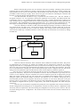
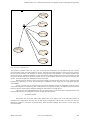
Bhaskar Joshi et al. / International Journal on Computer Science and Engineering (IJCSE) MICROCONTROLLER PIN CONFIGURATION TOOL Bhaskar Joshi1 , F. Mohammed Rizwan2, Dr. Rajashree Shettar3 1 Senior Staff Engineer, Infineon Technologies private limited, Bangalore, Karnataka, [email protected] M.tech , Computer Science and Engineering,RVCE, Bangalore,Karnataka,[email protected] 3 Professor, Computer Science and Engineering, RVCE, Bangalore,Karnataka,[email protected] Abstract 2 Configuring the micro controller with large number of pins is tedious. Latest Infine on microcontroller contains more than 200 pins and each pin has classes of signals. Therefore the complexity of the microcontroller is growing. It evolves looking into thousands of pages of user manual. For a user it will take days to configure the microcontroller with the peripherals. We need an automated tool to configure the microcontroller so that the user can configure the microcontroller without having in depth knowledge of microcontroller. By having just basic knowledge of microcontroller the user can configure the microcontroller. In this paper we discuss the way in which the tool can be developed and the design of algorithm is discussed here. Thus, we can come up with a micro controller pin configuration tool which will make the user configure the micro controller in few minutes which will perhaps take days to configure for a skilled hardware engineer. Index terms- Graphical pin assignment, configuration tool. INTRODUCTION The current challenge is the high level of complexity present in the high end Infineon micro controller. The high end micro controller contains more than 200+ pins and each pin can be configured with 10-15 different types of signals and each signal has different classes of strength. It is humanly very difficult to manually configure the micro controller. Therefore we need a intelligent tool which can do all of the above things and make the user easily configure the micro controller. Currently there are tools available in the market. But in this paper we discuss about the tool which is very user friendly and rich in functionalities. The tool comes up with easy to use options and very intuitive so that with minimum number of clicks we can complete configuring the microcontroller. The tool is developed to configure only the Infineon microcontroller. The tool is designed keeping Infineon microcontroller in mind. 1. SYSTEM MODEL I. Architecture The System comprises of two parts. It is depicted in fig.1. One is the front end and the other is the backend. The front end consists of user interface (UI) model. The UI model is well designed and well structured so that the user can configure the microcontroller using the tool in a easier way. We try to make the UI model very elegant, consistent et all. The back end is the solver part. The solver is an algorithm which makes decision has to whether the microcontroller pin can be connected to driver pin or not. The decision is taken by the solver in runtime. It takes the decision by running up through many queries and checking the values of the registers, previously set values and many other facts. Optimising the algorithm will make the tool better. Much of time has to be spend to optimise the algorithm with innovative techniques. The user selects the driver pin and the microcontroller pin which he wishes to connect. Then tells the system to solve it for the user. The tool runs a complex algorithm to solve the user’s query. The proposed plan for writing the algorithm depends upon the requirements of the microcontroller and requirement of the applications on the microcontroller device. Each Microcontroller will have constraints. The constraints are devised as connectivity. Only a particular pin of microcontroller can connect to particular pin of driver. For example a pin of driver can be connected to a predefined set of microcontroller pins. It cannot be connected to any other set. ISSN : 0975-3397 Vol. 4 No. 05 May 2012 886 Bhaskar Joshi et al. / International Journal on Computer Science and Engineering (IJCSE) Before connecting the pins the user can check the connection possibility. Checking of the connection possibility takes less time compared to actually connecting the pins which makes the tool faster. Perhaps, the input parameters for the solver is the signal name and pin number of the microcontroller , the signal name and pin number of driver and type of query. There can be two types of Connections. Checking the connection and the other is connecting the pins which modifies the solver database. The Microcontroller and Driver in fig 1 represent the user interface part. The user interface is developed in Eclipse. It is very important to develop the application tool in Eclipse. The Microcontroller Pin Configuration Tool is a very sophisticated and complex tool. It has a complex algorithm and contains lot of logic. Perhaps, the tool is highly scientific and we need a suitable platform to develop the tool.[1] Therefore we go for Eclipse. Pin Configuration tool is high performance tool. It is a long process to develop the tool. We need support for multiple runtime, multiple debugging and versioning support. It is packed with eclipse.[1] The solver database is realised as a XML (Extensible Markup Language). The XML is simplest of data store which the user can think of [2]. All the microcontroller information is stored in XML file. As the user configures the microcontroller the state of XML file changes. The changes means that the defined register values stored as XML tags is modified. Therefore current state of the microcontroller can be known by reading the XML file. User Solver Database Solver Microcontroller Driver Fig 1: System model of Configuration tool. These are called as constraints. These constraints will be defined as variables and values. The process of configuration goes recursively [3]. Initially the available pins are shown throw constraints. It is kind of mapping where there is 1:n mapping between a driver pin and a microcontroller pin where n is a positive integer whose size will never become more than half the total number of pins in the whole microcontroller. When the pins are selected then the available pins will be reducing and the pins will be configured. The user will also be setting some more parameters apart from the selection of pin such as frequency, baud rate, signals etc. Once the pins are configured it should be removed from the list of available pins from the constraints to maintain the consistency. The pins can be considered as resources. The tool should never give away all of its resources to less frequently used pins. Therefore the resources should be preserved for high priority pins.[4] When the request is made by the user. The request has to be fulfilled with minimum number of resources. Filling the request with minimum number of resources will make the tool very efficient. Among the pool of microcontroller pins that can be assigned to the driver pin. Priorities as to be set for these pins in the pool. Priorities will be set according to the demand for the pins. Most demanded pin will have the highest priority. Pins should be assigned from low priority to high priority. This kind of arrangement will avoid from poor assignment. If the user opts for automatic assignment then perhaps the solver algorithms will run many iterations to find the configurations and among the set of configurations it found it will choose the best configuration which will satisfy the user requirements. The choice among the configurations can also be given to the user. The user can choose among the set of configurations. The iteration will be carried out in few seconds so that the user is not delayed. ISSN : 0975-3397 Vol. 4 No. 05 May 2012 887 Bhaskar Joshi et al. / International Journal on Computer Science and Engineering (IJCSE) There can be 2 types of connection. a. Check for connection possibility. b. Connect. The first option just checks for connection. It will run few instructions to find out the connection possibility. Intuitively we can notice that checking the connection will take less time when compare to connecting the pins. Since connecting will change some constraint values which takes more time. Whereas checking the connection option will just check for equality. It is called as unification. For example let t1 and t2 be two constraints . t1=t2 can be true or false. If it is true it runs through a set of instructions and if it is false then it runs through some other set of instructions. Most of the code of solver runs with the principal of unification. Now the procedural program that is written in prolog takes the query has input and runs through the procedure and finds out the solution in no time and gives the output to the user. The user can then proceed with further connections recursively [5]. II. Working of Solver The solver is designed using Constraint Programming System [5][6]. The constraint programming system is designed using Prolog. Prolog is a constraint logic programming (CLP) which is used for constraint solving mechanisms [7]. Here the problems are allocation of resources, scheduling and giving priorities. These problems can be solved using constraint logic programming. Prolog is a procedural language. It takes final decision based on some constraints. Constraint logic programming reduces the development effort. It is easy to design and modify. And an important point to note is, using prolog we cannot store anything. The program written using prolog is just like an algorithm. As we know an algorithm cannot store anything. If given an input to the algorithm it comes out with outputs. Firstly we define the constraints which will have pairs of objects and values. Objects can be a String, Integer or another object. These objects will also have values. The value will be stored in solver database. During the runtime the value might be changed. When the user selects the peripheral pin, the system gives him a set of microcontroller pins. The user can connect to any of the pins from the set. But one pin of peripheral can be connected to only one pin of the set prompted to the user. The user selecting multiple pins of microcontroller for one pin of peripheral will be invalid and the tool will not allow becoming invalid. This is done to maintain the consistency of the system. The constraints will also have default values. If the user doesn’t wish to configure some pins then the tool automatically configures the pins with the best possible available configuration value. The best possible configuration value shall be decided on run time. A query is picked up from the user. The query consists of five parameters. 1. Microcontroller pin number 2. Microcontroller signal name 3. Peripheral signal name 4. Peripheral pin number 5. Type of connection. conn([port,3,pad,0],pad,[ccu6,0,cc,0],cc,Option). III. Use Case Model Use case is the factor which always comes into picture before designing the system. It says how in the world the system is contributing. Fig.2 shows the use case of the system. To start with the user selects the microcontroller among the myriad of the microcontrollers. After the selection, the graphical tool shows a user friendly controls which consists of a microcontroller picture and the driver pictures which closely relates to the real world components. We do this so that the user is close to the hardware virtually. The features are added with Eclipse Modelling Framework (EMF) which has a rich set of graphics as their package [7]. The drivers are ISSN : 0975-3397 Vol. 4 No. 05 May 2012 888 Bhaskar Joshi et al. / International Journal on Computer Science and Engineering (IJCSE) added from the list of drivers shown in the UI. Once any driver is selected a transition effect is shown in the UI which puts the driver inside the micro controller picture. The user can then configure the pins of the pads and solve for the connection. Once the configuration of any peripheral gets completed then the user can remove the driver from the UI and put back into the list of drivers. Since there are many drivers, placing everything inside the microcontroller component is very difficult. Thus, we go with the above procedure. He can repeat the process intuitively so as to configure the drivers according to the user requirements and according to the applications required by the user. It is not necessary for the user to solve the pins individually. All the pins can be connected and all the connections can be solved at a time. When all the connection are set and passed the query then the input to the solver is the array of requests. The solver solves the array of requests sequentially. The conflicts raised during the configuration are popped up to the user and other options that the user can choose to resolve the conflict is shown intelligently. User friendlessness is given a top priority when developing the tool. The tool is given as easy to access, easy to use, easy to understand and less complex. The tool is given with rich graphics which removes the traditional graphics of C++ and C# language. JAVA is used for creating the tool. JAVA contains plug-in which provides good graphics. Some of the plug-in are: SWT JFace Draw2d Zest Nebula These plug-in provide rich graphics to the tool. Firstly functionalities are well tested and checked for perfection and then the graphic tool is well designed and groomed. Giving an excellent design without that of functionality will fail the system. The user has to configure the remaining of the section as intelligently as possible so that the user gets the expected result from the tool. Many Artificial Intelligence methods or algorithms have to be used so that the working of tool is very close to the user manually configuring the tool. ISSN : 0975-3397 Vol. 4 No. 05 May 2012 889 Bhaskar Joshi et al. / International Journal on Computer Science and Engineering (IJCSE) uc MC configurator Microcontroller Selection Add Driv er User Driv er pin selection Microcontroller pin selection Automatic Pin configuration Solv e Remov e driv er Fig2: use case of configuration tool. The system is scalable. That is at any point of time the microcontrollers can be added in the tool. Newest microcontroller comes out of the market in no time. Therefore with small changes in the tool, it has to work for the new microcontrollers. The changes are done in GUI and the solver database. Two separate databases are used in the system. An abstract database for the user interface which contains the necessary information so that the microcontroller and drivers are shown in the controls. A full database which the solver uses to solve the user queries. It consists of full state information of microcontroller. Blocked pins are shown in the UI tool and we make sure that the user does not go for configuring the blocked pins. Therefore we show the blocked pins in different colour saying the user that these pins are untouchables. At any point the user can reverse the process. He can undo the process of configuring. Undoing will be useful when the pins are conflicting. That is the pins are in a tie and the tie has to be untied. The tie can also be broke by the tool which employs artificial intelligence and heuristics to break the tie. Once the pins are configured then the user can generate the C code. If the user is adjusted with the tool then the whole process of configuration can be completed in few minutes. 3. FUTURE WORK The system has to be rich. Many other features has to be added. One of the important features is automatic pin configuration. The user may do half of the configuration and rest leave it to the tool. The tool should be scalable to all future microcontrollers. With minimum changes the tool has to work with new microcontrollers. ISSN : 0975-3397 Vol. 4 No. 05 May 2012 890 Bhaskar Joshi et al. / International Journal on Computer Science and Engineering (IJCSE) 4. CONCLUSION This tool aims to solve major problem faced by embedded software/Automotive Applications Development Teams in Automotive domain. Generally silicon vendors like Infineon spends lot of money/effort in supporting customers for pins assignment and resource management. This tool is planned to apply innovative approach to solve this problem. This is one of unique projects in the industry. The tool could be also extended to a more fully automated prototype platform generation system. 5. [1] [2] [3] [4] [5] [6] [7] REFERENCES Jacob A. Berlier and James M. McCollum, “A Constraint Satisfaction Algorithm for Microcontroller Selection and Pin Assignment” 10.1109/SECON.2010.5453854 pp 348-351 March 2010 Nambiar,U.; Lacroix,Z.; Bressan, S.; Mong Li Lee; Yingguang Li; “Current approaches to XML management” Volume: 6, Issue: 4, pp: 43-51 August 2002 Roman Bartak “Constraint propagation and backtracking- Based search” Citeseer pp 1-42 2005 Gregory R. Watson and Nathan A. DeBardeleben “Developing Scientific Applications Using Eclipse” Volume 8, Issue 4 pp 50-61 August 2006 Thom Fruhwirth, Alexander Herold,Volker Kuchenhoff, Thierry Le Provost,Pierre Lim,Eric Monfroy, Mark Wallace “Constraint logic programming” . Volume 636, pp3-35, 1992 Krzysztof, Apt and Mark Wallace “Constraint logic programming using ECLiPSe “ISBN: 9780521866286: December 2006 Dave Steinberg, Frank Budinsky, Marcelo Paternostro, Ed Merks “EMF: Eclipse Modeling Framework”, 2nd Edition ISBN-10: 0321331885 Dec 2008 ISSN : 0975-3397 Vol. 4 No. 05 May 2012 891