1
Bhaskar Joshi et al. / International Journal on Computer Science and Engineering (IJCSE)
Before connecting the pins the user can check the connection possibility. Checking of the connection
possibility takes less time compared to actually connecting the pins which makes the tool faster. Perhaps, the
input parameters for the solver is the signal name and pin number of the microcontroller , the signal name and
pin number of driver and type of query. There can be two types of Connections. Checking the connection and
the other is connecting the pins which modifies the solver database.
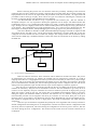
The Microcontroller and Driver in fig 1 represent the user interface part. The user interface is
developed in Eclipse. It is very important to develop the application tool in Eclipse. The Microcontroller Pin
Configuration Tool is a very sophisticated and complex tool. It has a complex algorithm and contains lot of
logic. Perhaps, the tool is highly scientific and we need a suitable platform to develop the tool.[1] Therefore we
go for Eclipse. Pin Configuration tool is high performance tool. It is a long process to develop the tool. We
need support for multiple runtime, multiple debugging and versioning support. It is packed with eclipse.[1]
The solver database is realised as a XML (Extensible Markup Language). The XML is simplest of data
store which the user can think of [2]. All the microcontroller information is stored in XML file. As the user
configures the microcontroller the state of XML file changes. The changes means that the defined register
values stored as XML tags is modified. Therefore current state of the microcontroller can be known by reading
the XML file.
User Solver Database Solver Microcontroller Driver Fig 1: System model of Configuration tool.
These are called as constraints. These constraints will be defined as variables and values. The process
of configuration goes recursively [3]. Initially the available pins are shown throw constraints. It is kind of
mapping where there is 1:n mapping between a driver pin and a microcontroller pin where n is a positive integer
whose size will never become more than half the total number of pins in the whole microcontroller. When the
pins are selected then the available pins will be reducing and the pins will be configured. The user will also be
setting some more parameters apart from the selection of pin such as frequency, baud rate, signals etc.
Once the pins are configured it should be removed from the list of available pins from the constraints to
maintain the consistency. The pins can be considered as resources. The tool should never give away all of its
resources to less frequently used pins. Therefore the resources should be preserved for high priority pins.[4]
When the request is made by the user. The request has to be fulfilled with minimum number of resources.
Filling the request with minimum number of resources will make the tool very efficient. Among the pool of
microcontroller pins that can be assigned to the driver pin. Priorities as to be set for these pins in the pool.
Priorities will be set according to the demand for the pins. Most demanded pin will have the highest priority.
Pins should be assigned from low priority to high priority. This kind of arrangement will avoid from poor
assignment.
If the user opts for automatic assignment then perhaps the solver algorithms will run many iterations to
find the configurations and among the set of configurations it found it will choose the best configuration which
will satisfy the user requirements. The choice among the configurations can also be given to the user. The user
can choose among the set of configurations. The iteration will be carried out in few seconds so that the user is
not delayed.
ISSN : 0975-3397
Vol. 4 No. 05 May 2012
887