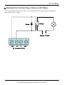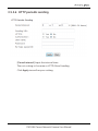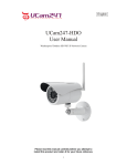
1
PLC-128 series
720P
USER MANUAL
VERSION 1.1
Table of Contents
1.0 Product Overview ............................................................................................ 5
1.1 Package Contents ................................................................................................................ 5
1.2 System Requirements ........................................................................................................ 5
1.3 Introduction .......................................................................................................................... 6
1.4 Hardware Overview ............................................................................................................ 8
2.0 Installation ....................................................................................................... 10
2.1 Hardware Installation ...................................................................................................... 10
2.1.1 Sensor Unit Installation .................................................................................... 10
2.1.2 Main Unit Installation........................................................................................ 13
2.1.3 Restore Camera back to factory settings .................................................. 16
2.1.4 Wireless Installation with WPS function...................................................... 17
2.1.5 Wireless Installation Considerations............................................................. 18
2.1.6 General I/O Terminal ......................................................................................... 19
2.2 Quick installation for iOS device ................................................................................ 25
2.2.1 Camera installation on iOS device ............................................................... 25
2.2.2 Wireless Setup on iOS device ........................................................................ 28
2.2.3 Advanced settings on iOS device ................................................................ 31
2.3 Quick installation for Android device ....................................................................... 35
2.3.1 Camera installation on Android device ..................................................... 35
2.3.2 Wireless Setup on Android device ............................................................... 38
2.3.3 Advanced settings on Android device ....................................................... 41
2.4 Camera installation on PC ............................................................................................ 44
2.4.1 Camera Live installation on PC .................................................................... 44
2.4.2 Add a camera to Camera Live ...................................................................... 44
2.4.3 Play, Delete and Modify cameras ................................................................ 46
2.4.4 Muliti-viewing on one screen ........................................................................ 48
2.4.5 Video recording, Storage and Viewing ....................................................... 49
2.4.6 Snapshots, Storage and Viewing .................................................................. 50
2.5 Installation via Web Browser ........................................................................................ 51
2.5.1 Viewing Camera via Web Browser .............................................................. 51
2.5.2 Wireless Setup on PC via Web Browser .................................................... 52
3.0 Advanced Configuration ............................................................................ 57
3.1 Network Camera Setting Interface .......................................................................... 55
3.2 Camera................................................................................................................................ 57
3.2.1 Camera Setup ...................................................................................................... 57
PHYLINK Covert Network Camera User Manual
3.2.2 Stream Setup ......................................................................................................... 58
3.2.3 OSD Setup ............................................................................................................... 61
3.3 Network............................................................................................................................... 62
3.3.1 Wireless Setup........................................................................................................ 62
3.3.2 TCP/IP Setup........................................................................................................... 64
3.3.3 DDNS Setup............................................................................................................ 65
3.3.4 UPNP Setup............................................................................................................ 68
3.4 Storage ................................................................................................................................ 70
3.4.1 Storage Setup ........................................................................................................ 70
3.4.2 Browse Storage .................................................................................................... 71
3.4.3 Format SD Card ................................................................................................... 71
3.4.4 Recording to NAS ............................................................................................... 72
3.5
.
3.6
3.7
Task ................................................................................................................................ 75
3.5.1
Motion Detection ......................................................................................... 75
3.5.2
Schedule Setup .............................................................................................. 77
3.5.3
Task Management ......................................................................................... 78
3.5.3.1
Email alarm sending .......................................................................... 79
3.5.3.2
Email periodic sending ..................................................................... 81
3.5.3.3
FTP alarm sending .............................................................................. 82
3.5.3.4
FTP periodic sending ........................................................................ 84
3.5.3.5
HTTP alarm sending .......................................................................... 85
3.5.3.6
HTTP periodic sending ..................................................................... 86
3.5.3.7
Snapshot to storage on alarm ........................................................ 87
3.5.3.8
Snapshot to storage periodically .................................................. 88
3.5.3.9
Record to storage on alarm ............................................................. 89
3.5.3.10 Record to storage continuously .................................................... 90
3.5.3.11 Send files in storage to FTP server................................................ 91
Tools ............................................................................................................................... 92
3.6.1
System Identity ............................................................................................... 92
3.6.2
User Management ........................................................................................ 93
3.6.3
Date & Time ..................................................................................................... 94
3.6.4
Backup or Reset ............................................................................................ 95
3.6.5
Firmware Upgrade ....................................................................................... 95
Advanced functions................................................................................................. 97
3.7.1
Wizard................................................................................................................. 97
3.7.2
System................................................................................................................ 98
PHYLINK Covert Network Camera User Manual
4.0 Troubleshooting .............................................................................. 100
5.0 Technical Specifications ................................................................. 102
6.0 Glossary of Terms ........................................................................... 103
7.0 Technical Support .......................................................................... 105
PHYLINK Covert Network Camera User Manual
1.1 Package Contents
Verify the package contents against the list below.
PLC-128PW / PLC-128W / PLC-128P Main Unit
Camera Unit ( include 8 meter RJ11 cable)
Mounting Accessories
External Antenna (PLC-128P has no this item)
Manual and Software on CD-ROM
CAT5 Ethernet Cable
4 pin I/O connector terminal block
Power Adapter
Quick Install Guide
1.2 System Requirements
Minimum PC System Requirements
Operating system-Windows 2000/XP/Vista
/Windows 7/Mac/Linux
Processor-Intel Pentium III, 1GHz
Memory-256Mb RAM
Minimum Mac System Requirements
Operating system-Mac OSX 10.4 (Tiger)
Processor-800MHz-Power PC G4 or Intel
Memory-128Mb RAM (256Mb recommended)
Viewing System Requirements
Web Browser Setup/Viewing- IE Version 5.5 or later, Firefox,
Google Chrome, Safari & most other browsers
Real Player QuickTime and most other VLC players.
PHYLINK Covert Network Camera User Manual
1.3 Introduction
Professional Covert Network Security Camera
PHYLINK PLC-128 series is a small-sized, high-performance device perfect for covert
installations or where a discreet and compact surveillance solution is required.
Almost impossible to discover, which keeps it protected from vandalism.
Various and Flexible Mounting
PLC-128 series includes various mounting accessories for quick and easy installation.
The Sensor unit can be mounted flat or angled on any surface, using the angled
fastening bracket. The camera can also be mounted covertly behind a thin wall,
cupboard, door and etc. with miniature size design it enables easy integration into
any hidden place.
The sensor unit and main unit are connected by an 8 meter cable, providing
flexibility to place the sensor unit in one place and the main unit elsewhere.
Excellent Quality at Full Frame Rate
Excellent HDTV 720P video quality at full frame rate, Megapixel pinhole lens.
Works over Wi-Fi, Ethernet or Power over Ethernet (PoE) 802.3af.
WPS support for easy wireless setup.
Smart and Connectivity
General I/O which is used to connect external alarm devices like PIR sensor,
Gas Detector and etc.
Audio line in for security sound monitor pickup device.
Multi-zone Motion Detection and adjustable sensitivity, alerts by Email or Push
Notifications (for iOS and Android).
Built-in Micro SD card Slot up to 128GB (SD Card not included) with remote playback
from anywhere. Free iPhone, Android Apps for Quick & Easy remote Viewing.
PHYLINK Covert Network Camera User Manual
Approval Information
All our products meet the requirements of approval FCC or CE, and are granted the
FCC or CE certification. They are authorized to bear FCC or CE mark.
FCC
This equipment has been tested and found to comply with the limits for a Class B
digital device, pursuant to Part 15 of the FCC rules. These limits are designed to
provide reasonable protection against harmful interference in a residential
installation. This equipment generates, uses and can radiate radio frequency energy
and, if not installed and used in accordance with the instructions, may cause harmful
interference to radio communications.
However, there is no guarantee that interference will not occur in a particular
installation. If this equipment does cause harmful interference to radio or television
reception, which can be determined by turning the equipment off and on, the user is
encouraged to try to correct the interference by one or more of the following
measures: -Reorient or relocate the receiving antenna. -Increase the separation
between the equipment and the receiver. -Connect the equipment into an outlet on
a circuit different from that to which the receiver is connected. -Consult the dealer or
an experienced radio/TV technician for help.
This device complies with Part 15 of the FCC Rules. Operation is subject to the following
two conditions:
(1) This device may not cause harmful interference, and
(2) this device must accept any interference received, including interference that may
cause undesired operation Changes and modification not expressly approved by the
manufacturer or registrant of this equipment can void your authority to operate this
equipment under Federal Communications Commissions rules.
CE
This product complies with standards including Low Voltage Device Directive
73/23/EEC; EMC Directive 89/336/EEC and R&TTE Directive 1999/5/EC. It passed the
subject tests by the authority concerned and is authorized to bear CE mark.
PHYLINK Covert Network Camera User Manual
1.4 Hardware Overview
4
6
7
5
1.
2.
3.
4.
Main Unit
Status indicator LED
External Antenna
RJ12 Connector for
Sensor Unit
5. Audio Line In/MIC
6. Micro SD Card slot
7. SMA connector
3
1 2
12
15
13
16
Line In/MIC
14
CAM
8. Ethernet RJ45 connector
9. General I/O Terminal
10. Power Connector
11. Reset/WPS Button
8
10
9
11
I/O
LAN
Reset
12.
13.
14.
15.
16.
17.
17
Sensor Unit
RJ11 Cable
RJ12 Plug
Cover
Straight mounting bracket
Angled mounting bracket
DC12V
PHYLINK Covert Network Camera User Manual
Power Connector
Connects to the included DC 12V power adapter.
Reset/WPS Button
Short press this button to setup a wireless connection automatically (WPS function).
Press this button for 5 seconds to reset the camera. All settings will be restored to
factory default.
Note: PLC-128P has no WPS function.
Status indicator LED
After Main Unit is powered on, the indicator LED shows yellow light and quickly off
which means the system is being started. When the indicator LED shows yellow
again, it means the system has started successfully.
The indicator LED flashes during data transfer and shows red light for WPS connection
status.
Micro SD Card slot
Local storage for storing recorded image and video.
Sensor Unit and RJ11 Cable
The sensor unit and main unit are connected by an 8 meter cable, providing flexibility
to place the sensor unit in one place and the main unit elsewhere.
IMPORTANT!
The sensor unit is not approved for outdoor use. The product may only be installed
in indoor environments.
Mounting Accessories
PLC-128 series include various mounting brackets for quick and easy installation.
The sensor unit can be mounted flat or angled on any surface, using the angled
mounting bracket. The camera can also be mounted covertly behind a thin wall,
cupboard, door and etc. With miniature size design it enables easy integration into
any hidden place.
General I/O Terminal
Used to connect the external wired alarm devices like PIR sensor, gas detector, siren, etc.
PHYLINK Covert Network Camera User Manual
2.1 Hardware Installation
PLC-128 series is a small-sized, high-performance network camera perfect for covert
installations or where a discreet and compact surveillance solution is required.
Almost impossible to discover, which keeps it protected from vandalism.
2.1.1 Sensor Unit Installation
The PLC-128 series can be mounted in three different ways:
Flat on any surface
Angled on any surface, using the angled fastening bracket
Covertly behind a thin material, for example a thin wall, cupboard, door and etc.
Flat Surface Installation
1. Put the Sensor Unit to the wall or ceiling, using screws and plugs appropriate for
the wall/ceiling material.
2. Snap on the cover.
3. Proceed to install the Main Unit, see 3.2 Main Unit Installation.
1
2
PHYLINK Covert Network Camera User Manual
Angled Surface Installation
1. Put the angled mounting bracket to the wall or ceiling, using screws and plugs
appropriate for the wall/ceiling material. Ensure that the bracket is pointing
towards the area to be monitored.
2. Assemble the plate with the screw and align it so the arrows are vertical or horizontal.
3. Put the Sensor Unit to the plate with the two screws.
4. Snap on the cover.
5. Proceed to install the Main Unit, see 3.2 Main Unit Installation.
1
2
3
4
PHYLINK Covert Network Camera User Manual
Covert Installation
1. Drill a hole with 3mm diameter in the wall or ceiling. If the material is thicker than
1mm it may be necessary to expand the hole.
2. Pull off the protection on the adhesive and attach the straight mounting bracket
to the wall.
3. Insert the Sensor Unit into the bracket, and fix with the stop screw. Ensure that the
cone of the Sensor Unit is flush with the wall.
4 Proceed to install the Main Unit, see 3.2 Main Unit Installation.
1
2
3
PHYLINK Covert Network Camera User Manual
2.1.2 Main Unit Installation
Connect the sensor unit to the main unit
The Sensor Unit and Main Unit are connected by an 8 meter cable, providing flexibility
to place the Sensor Unit in one place and the Main Unit elsewhere.
Insert the RJ11 Plug into the RJ11 Jack on Main Unit.
IMPORTANT!
The RJ11 Plug must be insert into RJ11 Jack before the Main Unit is powered on.
Shorten Sensor Unit Cable
If required, the cable can be shortened. The sensor unit is delivered with a
8 meter (26 ft) RJ11 cable.
To shorten the cable follow these steps:
1. Cut the cable to the desired length. Measure from the sensor unit.
2. Strip the plastic outer coating from the end of the cable.
1
PHYLINK Covert Network Camera User Manual
2
3. Flatten the colored wires in the order described below.
RJ -12 Plug
Position NO.
RJ -11 Cable
Colored wires
1
White/orange
2
orange
3
Null
4
Null
5
White/Green
6
Green
4. Insert the wires all the way into a 6P6C RJ12 Plug.
Make sure that the wires stay in the correct order.
5. Use a crimping tool to fasten the connector to the cable.
Green
White/Green
4
Position 6
White/brown
brown
Position 1
PHYLINK Covert Network Camera User Manual
5
Connect Network and Power
Connect the Main Unit to your router or switch using the network cable.
Using the included power adaptor, plug one end into the Power Connector and plug
the other end into a power outlet.
Main Unit Panel
I/O
LAN
Reset
DC12V
DC Power Cable
Network Cable
Router
Note: The DHCP sever and UPnP must be enabled on your router (which is default
setting on most router) to assign a local IP address to the network camera.
If needed, please refer to your router's user manual on how to enable DHCP server
and UPnP.
Connection Using a PoE Switch or PoE Injector
The PLC-128PW can be either connected with Power Adaptor and network cable, or
optionally with a CAT-5 network cable that is connected to an 802.3af compatible
PoE Switch or PoE Injector. Under this condition, the network cable will transmit both
power and data over a single cable and you don’t need to connect the power adapter.
IMPORTANT!
Please note that for initial setup, you need to connect the camera directly to your
router or switch with a network cable. You can NOT connect wirelessly to the
camera without first setting it up via a network cable. After initial setup only the
power cable is required for the Wi-Fi connection.
PHYLINK Covert Network Camera User Manual
Mount the antenna
If using a Wi-Fi connection, the provided external antenna must be mounted to the
SMA connector on the Main Unit. Please keep the antenna vertical for better signal
strength.
Mount the Micro SD Card
The Micro SD Card must be insert to the slot before the Main Unit is powered on.
Note: The camera only supports FAT32, if the SD card is NTFS or Non FAT32 format,
you need to format it in FAT32 on PC.
2.1.3 Restore Camera back to factory settings
If you ever forget your admin password or have any other reason to reset the camera
to its factory settings, please use the following procedure:
Make sure the camera is powered up.
It is easier to use the software reset function. Login the web server of camera and
browse to Setting > Tools > Backup or Reset.
If hardware reset is needed, find the Reset/WPS Button on the Main Unit.
Hold the Reset/WPS Button down for at least 5 seconds, you’ll see the
Status indicator LED go off for a few seconds. This indicates reset is in progress.
Reset/WPS button
I/O
LAN
Reset
DC12V
A few seconds later the camera will restart and is now at factory settings. After reset the
user name and password will both be “admin” again.
PHYLINK Covert Network Camera User Manual
2.1.4 Wireless Installation with WPS function
You may create a Wi-Fi connect using the Reset/WPS Button on the Camera Cable.
Step 1
After the camera is powered on, short press the Reset/WPS button on the Main Unit
and the Status indicator LED will blink red light.
Short press the
Reset/WPS button
I/O
LAN
Reset
DC12V
Status indicator LED
will blink red light
Step 2
Press the WPS button on your router within 60 seconds.
WPS function also called QSS (Quick Secure Setup) on some brands of router.
The camera will automatically create a wireless connection to your router.
While connecting, the Status indicator LED will always on and your camera will reboot.
Note: On some routers, you may need to login to the web interface and then click
on an onscreen button to activate the WPS feature. If you are not sure where the
WPS button is on your router, please refer to your router’s User Manual.
PHYLINK Covert Network Camera User Manual
2.1.5 Wireless Installation Considerations
The wireless network camera lets you access your network using a wireless
connection from anywhere within the operating range of your wireless network.
However, the number, thickness and location of walls, ceilings, or other objects
that the wireless signals must pass through, may limit the range. Typical ranges
vary depending on the types of materials and background RF (radio frequency)
noise in your home or business. The key to maximizing wireless range is to follow
these basic guidelines:
1. Minimize the number of walls and ceilings between your adapter and other
network devices (such as your Network Camera) - each wall or ceiling can reduce
your adapter’s range from 3-90 feet (1-30 meters).
2. Be aware of the direct line between network devices. Position your devices
so that the signal will travel straight through a wall or ceiling (instead of at an
angle) for better reception.
3. Building Materials make a difference. A solid metal door or aluminum studs
may weaken the wireless signal. Try to position your wireless routers and wireless
network camera where the signal passes through drywall or open doorways.
4. Keep the wireless network camera at least 3-6 feet or 1-2 meters away from
electrical devices or appliances that generate RF noise.
5. If you are using 2.4GHz cordless phones or other radio frequency sources (such
as microwave ovens), your wireless connection may degrade dramatically or drop
completely. Make sure your 2.4GHz phone base is as far away from your wireless
network camera as possible. The base transmits a signal even if the phone in not
in use.
IMPORTANT!
The megapixel wireless camera requires a 4 out of 5 bar or 5 out of 5 bar signal
strength in the camera's system status page for a reliable wireless connection
with real-time video streaming. With a typical consumer grade router you should
expect the camera to work reliably 40 to 50 feet (12 to 15 meters) from the
router, with one wall in between. If the signal strength less than 3 out of 5 bar,
you may need a Wi-Fi range extender.
PHYLINK Covert Network Camera User Manual
2.1.6 General I/O Terminal
POWER
DO
DI
GND
I/O
LAN
Reset
DC12V
PLC-128 series provides a general I/O terminal which is used to connect external wired
alarm devices like PIR sensor, Gas Detector, etc.
The terminal definitions are described below :
Specification
Pin NO.
Name
1
POWER
2
DO
Digital output , Max. 40VDC, max. 400mA
3
DI
Digital input, OPEN/Short-to-GND
4
GND
12VDC ± 5%, max. 0.5A (For external device)
Ground
POWER
This terminal can provide DC power to a wired alarm devices.
The max power for external device. is 12VDC ± 5%, 0.5A .
This is a optional, you can use the alarm device with a external power supply.
IMPORTANT! - The rating voltage of alarm device can not less than 12VDC,
or you will damage the alarm device.
PHYLINK Covert Network Camera User Manual
DO
With a maximum load of 400mA and a maximum voltage of 40V DC, This terminal
has an open-collector NPN Darlington transistor with the emitter connected to the
GND terminal.
If used with an external relay, a diode must be connected parallel with the load,
for protecting against voltage transients.
Please refer to the following diagram for the connection method.
PWR
Be careful about choosing Open or Grounded when connecting to a alarm or
other device, you need to make the relevant settings to the camera
as the picture below:
Live View
Wizard
System
Support
Reboot
Camera
Digital I/O Setup
Network
Digital input:
Active state is:
Schedule:
Enable
Disable
Open
Grounded
Always
Storage
Task
Motion Detection
Digital I/O Setup
Enable
Digital output:
Active state is:
Post alarm:
Schedule:
Open
5
Always
Disable
Grounded
seconds (1-99)
Schedule Setup
Task Management
Tools
Apply
The Grounded means that DO short to GND inside the camera.
The Open means that DO is floating inside the camera.
PHYLINK Covert Network Camera User Manual
DI
This terminal which is used to connect the relay output of wired alarm device like
PIR sensor, Gas Detector, Infra-red pool alarm and etc.
Be careful about choosing Open or Grounded when connecting to the terminal of
alarm output, you need to make the relevant settings to the camera, do it like this:
setting--> Task--> Digital I/O Setup--> you can do it as the picture below:
Live View
Wizard
System
Support
Reboot
Camera
Digital I/O Setup
Network
Digital input:
Active state is:
Schedule:
Enable
Disable
Open
Grounded
Always
Storage
Task
Motion Detection
Digital I/O Setup
Enable
Digital output:
Active state is:
Post alarm:
Schedule:
Open
5
Always
Disable
Grounded
seconds (1-99)
Schedule Setup
Task Management
Tools
Apply
The Grounded means that DI is shorted to GND.
In this way, DI should be connected to N.O(Normal Open) terminal.
The Open means that DI is floating from GND.
In this way, DI should be connected to N.C (Normal Close) terminal.
GND
This terminal used to COM terminal for Relay output of alarm device.
When Terminal 1 connect +DC terminal of alarm device , please connect this
terminal to GND or –DC terminal of the device.
This is a optional, you can use the alarm device with a external power supply.
PHYLINK Covert Network Camera User Manual
Example For Connecting a Sensor Device
This example shows how to wire a PIR Detector to I/O Terminal BLOCK.
Connecting of PWR is a optional, you can use the alarm device with a
external power supply.
PHYLINK Covert Network Camera User Manual
Example For Connecting a Alarm Device
This example shows how to wire a Siren to I/O Terminal BLOCK.
PHYLINK Covert Network Camera User Manual
Example For Connecting a Device with Relay
This example shows how to wire a device to I/O Terminal BLOCK with a Relay and the device
use a external power supply.
PHYLINK Covert Network Camera User Manual
2.2 Quick installation for iOS device
2.2.1 Camera installation on iOS device
Search "PHYCAM" App from App Store, download and install it.
Start the App and then the "Add Camera" screen will appear.
17:50
iPhone
63%
Add Camera
QRCode
Add
Camera
Camera Found!
Found! (2)
(2)
VNW5V15K6RY7J4VWC7W1
192.168.168.102
THG5T55K2RY7K1VWC7XJ
192.168.168.103
Camera
Event
Playback
Add Camera
Info
There are three ways to add a camera on an iOS device.
Option 1
Search the camera in Local Area Network
If your camera is in the same Local Area Network with your smartphone, the
App can search the cameras automatically. If the camera UID shows up on list
then press the UID for the camera you are setting up.
17:50
iPhone
Add Camera
Cancel
Name
Camera
UID
THG5T55K2RY7K1VWC7XJ
Account
admin
Password
Password
63%
Save
Enter the "Password". ( The default password is "admin". )
Assign a "Name" to the camera to help identify this camera if more than one
camera is in use. ( The default name is "Camera". )
Press "Save" button and your camera will show up under “Camera List”.
PHYLINK Covert Network Camera User Manual
Option 2
Scan the camera UID using smart phone
Press "QRCode" button to scan the camera UID from the UID sticker on the Main Unit.
17:50
iPhone
63%
Add Camera
63%
Place a barcode inside the
viewfinder rectangle to scan it.
QRCode
Add
17:50
iPhone
Camera
Camera Found!
Found! (2)
(2)
VNW5V15K6RY7J4VWC7W1
192.168.168.102
THG5T55K2RY7K1VWC7XJ
192.168.168.103
Camera
Event
Playback
Add Camera
Info
Cancel
Light
Enter "Password". (The default password is "admin".)
Assign a "Name" to the camera to help identify this camera if more than one
camera is in use.
Press "Save" button and your camera will show up under “Camera List”.
Option 3
Manually type UID
If you camera is not in the same Local Area Network with your Smart phone,
the App can NOT search cameras for Local Network.
Press "Add" button and manually type "UID" according to the UID sticker on the
Main Unit.
Enter "Password". (The default password is "admin".)
Assign a "Name" to the camera to help identify this camera if more than one
camera is in use.
Press "Save" button and your camera will show up under “Camera List”.
PHYLINK Covert Network Camera User Manual
Press on the Camera name from “Camera List” for "Live View" using a wired connection.
iPhone
17:50
63%
Camera
Back
Live View
Online / LAN
768x432 / FPS: 16 / BPS: 154 Kbps
Press
to View saved pictures.
Press
to take a snapshot.
Press
to start listening or stop listening.
Press
to start speaking or stop speaking.
Press the "Back" button to go back to the “Camera List”.
PHYLINK Covert Network Camera User Manual
2.2.2 Wireless Setup on iOS device
There are two ways to setup wireless connection on iOS device.
Option 1
Quick setup with smart phone
from the Camera List and go to the Edit Camera.
Press on
17:50
iPhone
63%
Edit
Camera List
Camera
Connected
VNW5V15K6RY7J4VWC7W1
Camera
Connected
V5G5SX5U2TE71JBWC7W1
Camera
Event
Add Camera
Playback
Info
Go to Advanced Setting > Network Setup.
17:50
iPhone
Back
63%
Edit Camera
Name
Camera
Account
admin
Back
63%
17:50
iPhone
Advanced Setting
Motion Detection
Alarm Recording
Password
Microphone
Speaker
Not available
Connected
Reconnect
Video Quality
Security Code
Network Setup
Advanced Setting
Alarm Actions
Login Account
PHYLINK Covert Network Camera User Manual
Back
62%
17:52
iPhone
Network Setup
iPhone
Back
17:52
62%
WiFi Networks
CHOOSE A NETWORK...
WiFi Networks
D-Link_DIR-612
Data & Time
TP-Link_245416
FAST_11DA2E
phr-002
Press WiFi Networks , then the App will search for available wireless networks,
select your network among this list.
Type your Wi-Fi password and press the “Join” button to complete the Wi-Fi setup.
iPhone
Cancel
17:52
Enter Password
62%
Join
Password
After a successful wireless setup, you can remove the network cable and the camera should
work through the wireless network after a short delay.
PHYLINK Covert Network Camera User Manual
Option 2
Quick setup with WPS function
You may create a Wi-Fi connection using the Reset/WPS Button on the Main Unit.
Step 1
After the camera is powered on, short press the Reset/WPS button on the Camera
and the Status indicator LED will blink red light.
Step 2
Press the WPS button on your router within 60 seconds.
WPS function also called QSS (Quick Secure Setup) on some brands of router.
The camera will automatically create a wireless connection to your router.
While connecting, the Status indicator LED will always on and your camera will reboot.
Note: On some routers, you may need to login to the web interface and then click
on an onscreen button to activate the WPS feature. If you are not sure where the
WPS button is on your router, please refer to your router’s User Manual.
PHYLINK Covert Network Camera User Manual
2.2.3 Advanced settings on iOS device
Video Quality
There are two pre-programmed stream profiles: primary stream and
secondary stream. These streams profiles help for quick setup.
The settings for these can be adjusted. Press on
stream profiles.
iPhone
17:52
Back
Video Quality
for the settings of
62%
iPhone
17:52
Back
Stream Setup
Best
Primary Stream
Good
Image Size
50Hz
Confirm
Medium
Secondary Stream
Environment Mode
62%
Poor
640x480
Frame Per Second
Bitrate (Kbps)
Horizontal Flip
15
512
Vertical Flip
Pre-Recording (sec)
On-Screen-Display
0
Disable
There are four quality level of video can be set quickly.
You can also make further changes to the details of quality.
Please note that the higher the video quality, the more network bandwidth you will
need to support it.
[ Environment Mode ] Two options: 50Hz & 60Hz. Set according to the mains
frequency in the country of use.
For UK this would be 50Hz. For US this would be 50Hz.
[ Pre-Recording ] The Pre-Recording Time control how long the video is
recorded before motion detection is detected by a camera. You can fill a value
of seconds to adjust this times.(The Max value is 10 seconds)
Video pre-recording allows the camera to record up to 10 seconds of video
leading up to a related trigger event. It will allows users to review the
moments before the camera was triggered.
Moving objects triggered motion detection recording function, but the
delay problems caused the loss of data images in the beginning of the
event, in some situations, these are very important. Video pre-recording
will help you catch everything.
PHYLINK Covert Network Camera User Manual
Alarm Actions
The camera refers to motion detection as an “alarm”. If any alarm occurs, the
camera can trigger a recording and send an email.
iPhone
17:52
Back
Alarm Actions
62%
Alarm Recording
Alarm Email
Press on
to enter the Alarm Recording settings or Alarm Email settings.
Alarm Recording
62%
iPhone
17:52
Back
Alarm Recording
Confirm
Alarm Recording
Record Stream
1st
Post-Recording (sec)
30
File Split (sec)
60
2nd
In the Alarm Recording settings, you can turn on or off the Alarm Recording feature.
You can select which stream profile to record.
[ Post-Recording ] The number of seconds that the camera should keep recording
video after motion stops. If there is any motion within this time the camera will keep
recording until there is no motion for the duration of this parameter. It can be from
5 seconds to 24 hours.
[File Split] The video can be recorded into many split files for better management
and index. You can set the recording time for each split file.
PHYLINK Covert Network Camera User Manual
Alarm Email
For automatic emailing you will need both a mail server and one or more email
receiving addresses.
If you don’t have this information handy you may want to refer to your internet
service provider’s help pages or other email program account settings.
SMTP Email Server Setting
iPhone
17:52
Back
Alarm Email
62%
Confirm
General Setting
Server
Port
25
SSL Connection
Email Sending
Snapshot Stream
Authentication
1st
2nd
Account
Email Interval (sec)
60
Password
Sender
In the Alarm Email settings, you can turn on or off the Alarm Email feature.
You can select the stream profile to snapshot for mail .
[ Email Interval ] Input the interval between two E-mails .
If you do not want to send mail too frequently, you can increase the time interval
to send the E-mail.
[Server] Input your E-mail’s SMTP server name.
[Port] 25, as default.
[SSL connection] Select OFF . For Gmail, select ON .
It depends on the mail system.
[Authentication] Select ON .
[Account] Input your E-mail user name.
[Password] Input your E-mail password.
[Sender] Input the sender mail address
[Receiver mail address] Input the receiver mail address.
PHYLINK Covert Network Camera User Manual
Receiver Setting
Receiver#1
Receiver#2
Receiver#3
Subject
Warning from Network...
Message
[Receiver#] Input the receiver mail address.
You can set up a total of three E-mail address.
[Subject] Input the subject of mail.
[Message] Fill with the content you want to send in the mail .
Note: Gmail requires that you go to your account settings on Gmail.com and enable
the POP feature (Post Office Protocol). If your Gmail account does not have POP
enabled, the camera will not be able to send email.
PHYLINK Covert Network Camera User Manual
2.3 Quick installation for Android device
2.3.1 Camera installation on Android device
Search "PHYCAM" App from Google Play, download and install it.
Start the App and then the following screen will appear.
20:46
PHYCAM
Click here to add camera
Press
to add a new camera.
There are three ways to add a camera
on the Android device.
Option 1 Search the camera in Local Area Network
If your camera is in the same Local Area Network with your smart phone,
the App can search the cameras automatically.
Enable Wi-Fi on Android device, press on “Search” button and the camera UID will shows up
on "Search camera from LAN" screen. Then press the UID for the camera you are setting up.
20:46
Search camera from LAN
Add Camera
TDGNUX5221EZ11BWC7EJ
192.168.168.105
Refresh
Device Setting
UID:
TDGNUX5221EZ11BW
Scan
Enter the "Password".
( The default Password is "admin". )
Assign a "Name" to the camera to help
identify this camera if more than one
camera is in use.
( The default name is "Camera". )
Press "OK" button and then the camera
will show up under the “Camera List”.
Account:
Search
admin
Password:
Camera
Name:
OK
PHYLINK Covert Network Camera User Manual
Cancel
Option 2
Scan the camera UID using smart phone
Press "Scan" button to scan the camera UID from the UID sticker on the Main Unit.
20:46
Barcode Scanner
Add Camera
Device Setting
UID:
Scan
Search
Place a barcode inside the viewfinder rectangle to scan it.
Enter "Password". (default password is "admin".)
Assign a "Name" to the camera to help identify this camera if more than one camera
is in use.
Press "OK" button and your camera will show up under “Camera List”.
Option 3
Manually type UID
If you camera is not in the same Local Area Network with your Smart phone,
the App can NOT search cameras for Local Network.
Press
and manually type "UID" according to the UID sticker on the Main Unit.
Enter "Password". (default password is "admin".)
Assign a "Name" to the camera to help identify this camera if more than one
camera is in use.
Press "Save" button and your camera will show up under “Camera List”.
PHYLINK Covert Network Camera User Manual
Press on the Camera name from “Camera List” for "Live View" using a wired connection.
20:46
PHYCAM
Camera
VNW5V15K6RY7J4VWC7W1
Online
Click here to add camera
Live View
Camera
Press
to view saved pictures.
Press
to take a snapshort of live view.
Press
to start listening or stop listening.
Press
to start speaking or stop speaking.
Press the “Back” button of Android to go back to the “Camera List”.
PHYLINK Covert Network Camera User Manual
2.3.2 Wireless Setup on Android device
There are two ways to setup wireless connection on Android device.
Option 1
Quick setup with smart phone
press and hold camera name until the menu shown below pops up.
And then press "Edit Camera".
20:46
PHYCAM
Camera
VNW5V15K6RY7J4VWC7W1
Online
Click here to add camera
Go to Advanced Setting > Network Setup and then press Wi-Fi Setting.
Note: The “Advanced Setting” at the bottom of Edit Camera page. Maybe you need
to scroll down the screen to find it.
20:46
Advanced Setting
Network Setup
Modify Security Code
Wi-Fi Setting
Advanced Setting
Wi-Fi Setting
SSID
None
Disconnect
D-Link_DIR-612
D-Link_DIR-612
TP-Link_245416
Press on the text box
to view list of
available networks. Select your network from
the list and type in your Wi-Fi password (also
known as wireless key), and press "OK" to
complete setup. After successful wireless setup,
remove the network cable and the camera
should work through the wireless network after
a short delay.
FAST_11DA2E
phr-002
PHYLINK Bullet HD User Manual
Option 2
Quick setup with WPS function
You may create a Wi-Fi connection using the Reset/WPS Button on the Main Unit.
Step 1
After the camera is powered on, short press the Reset/WPS button on the Camera
and the Status indicator LED will blink red light.
Step 2
Press the WPS button on your router within 60 seconds.
WPS function also called QSS (Quick Secure Setup) on some brands of router.
The camera will automatically create a wireless connection to your router.
While connecting, the Status indicator LED will always on and your camera will reboot.
Note: On some routers, you may need to login to the web interface and then click
on an onscreen button to activate the WPS feature. If you are not sure where the
WPS button is on your router, please refer to your router’s User Manual.
PHYLINK Covert Network Camera User Manual
2.3.3 Advanced Setting on Android device
Video Quality
There are two pre-programmed stream profiles: primary stream and secondary stream.
These streams profiles help for quick setup.
The settings for these can be adjusted. Press on
Video Setting
Advanced Setting
Motion Detection
for the settings of stream profiles.
ON
Primary Stream
Secondary Stream
Microphone
Speaker
Environment Mode
50Hz
Horizontal Flip
OFF
Vertical Flip
OFF
On-Screen-Display
disable
In the Advanced Setting , you can turn on or off the Motion Detection feature.
You can drag the volume bar to adjust the volume of speaker or Microphone.
There are four quality level of video can be set quickly.
You can also make further changes to the details of quality.
Please note that the higher the video quality, the more network bandwidth
you will need to support it.
[ Environment Mode ] Two options: 50Hz & 60Hz. Set according to the mains
frequency in the country of use.
For UK this would be 50Hz. For US this would be 50Hz.
[ Pre-Recording ] The Pre-Recording Time control how long the video is
recorded before motion detection is detected by a camera. You can fill a value
of seconds to adjust this times.(The Max value is 10 seconds)
Video pre-recording allows the camera to record up to 10 seconds of video
leading up to a related trigger event. It will allows users to review the
moments before the camera was triggered.
Moving objects triggered motion detection recording function, but the
delay problems caused the loss of data images in the beginning of the
event, in some situations, these are very important. Video pre-recording
will help you catch everything.
PHYLINK Covert Network Camera User Manual
Alarm Actions
The camera refers to motion detection as an “alarm”. If any alarm occurs, the
camera can trigger a recording and send an email.
Alarm Actions
Alarm Email
Alarm Recording
Press on
to enter the Alarm Recording settings or Alarm Email settings.
Alarm Recording
Alarm Recording
OFF
Record Stream
Alarm Recording
In the Alarm Recording settings, you can
turn on or off the Alarm Recording
feature. You can select which stream
profile to record.
1st
Post-Recording
30
File Split (sec)
60
[ Post-Recording ] The number of seconds that the camera should keep recording
video after motion stops. If there is any motion within this time the camera will keep
recording until there is no motion for the duration of this parameter. It can be from
5 seconds to 24 hours.
[File Split] The video can be recorded into many split files for better management
and index. You can set the recording time for each split file.
PHYLINK Covert Network Camera User Manual
Alarm Email
For automatic emailing you will need both a mail server and one or more email
receiving addresses.
If you don’t have this information handy you may want to refer to your internet
service provider’s help pages or other email program account settings.
Alarm Email
General Setting
Email Sending
OFF
Snapshot Stream
1st
Email Interval (sec)
In the Alarm Email settings, you
can turn on or off the Alarm
Email feature.
You can select the stream profile
to snapshot for mail .
[ Email Interval ] Input the interval
between two E-mails.
If you do not want to send mail too
frequently, you can increase the
time interval to send the E-mail.
Alarm Email
Email Server Setting
Server
Port
SSL Connection
OFF
Authentication
OFF
Account
[Server] Input your E-mail’s SMTP server
name.
[Port] 25, as default.
[SSL connection] Select OFF . For Gmail,
select ON . It depends on the mail system.
[Authentication] Select ON .
[Account] Input your E-mail user name.
[Password] Input your E-mail password.
[Sender] Input the sender mail address
[Receiver mail address] Input the receiver
mail address.
Password
Sender
PHYLINK Covert Network Camera User Manual
Alarm Email
Receiver Setting
Receiver#1
Receiver#2
Receiver#3
Subject
Message
[Receiver#] Input the receiver mail address. You can set up a total of three
E-mail address.
[Subject] Input the subject of mail.
[Message] Fill with the content you want to send in the mail .
Note: Gmail requires that you go to your account settings on Gmail.com and enable
the POP feature (Post Office Protocol). If your Gmail account does not have POP
enabled, the camera will not be able to send email.
PHYLINK Covert Network Camera User Manual
2.4 Camera installation on PC
2.4.1 Camera Live installation on PC
Insert provided installation CD into computer's CD-ROM drive and then the installation
window will appear. Click on the "Install Camera Live" button and follow the setup wizard
to complete the software installation.
Note: If the Installation CD program
does not start automatically open
CD-ROM drive and double click on
"autorun".
Install Camera Live
Documents
Exit
Double click the Phylink Camera Live icon to start the software after the
installation is completed.
Camera
Multilive
Video
Album
Setup
2.4.2 Add a camera to Camera Live
Click on
to add a camera, a pop-up window will appear as below.
PHYLINK Covert Network Camera User Manual
Add Camera
Discover
UID
Password
Name
OK
Option 1
Cancel
The camera is in your Local Area Network with your PC.
Click "Discovery" button, the program will automatically search for available
camera in Local Area Network. Select the required camera UID from the list.
Select Camera
T7S5TH5K2BYRS5BW87Z1 (PLC-325PW)
T5M5TN7U67A4VW87FJ2M (PLC-335PW)
SDS515A6FW5BC7X1UYSU (PLC-233PW)
EVUSJD78JDGHNVBWW76 (PLC-223PW)
OK
Cancel
Enter "password"( The default password is "admin"). Assign a "Name" to the camera
to help identify this camera if more than one camera is in use. Click on "OK" to save.
Wait for a few minutes, then the icon
will turn in green
, which means
camera is online and connection established, otherwise it's in disconnection status,
please check the UID and password you entered or your internet connection.
Option 2
If you camera is not in the same Local Area Network with your
PC, you can not discover the camera.
Manually type the camera UID according to the sticker on the camera cable or
product main body. The remaining steps are same, please refer to option 1.
After the above steps, you have completed a camera installation and you can view the
live video now.
PHYLINK Covert Network Camera User Manual
2.4.3 Play, Delete and Modify cameras
Click on
“menu” button to play/delete/modify camera.
Click on
”play” button for live viewing. Or you can double click on
the Camera preview for live viewing.
Click on
”delete” button to delete a camera has been added.
In the lower left corner of camera preview, there is a camera connection status
indication icon.
Camera preview
CVZMNUX5A6T2K5VM8RE7
Camera
This icon indicates that the camera is online and connection established.
This icon indicates that the camera is in disconnection status.
In this state you can not connect and view the camera.
Please check the UID and password you entered or your internet
connection. Also check the Hardware Installation of your camera.
PHYLINK Covert Network Camera User Manual
Click
”play” button or double click on a camera preview, enter the live viewing
mode. You can perform various operations with Play Control Panel at the bottom of live
viewing window.
Live Viewing Window
Camera
Multilive
Video
Album
Setup
1920x1080 8FPS 1.3Mbps
Play Control Panel
Take a snapshot
Record video
Speak talk back
Zoom in display ratio
Zoom out display ratio
Full screen viewing
Back cameras preview
Mute
Volume control bar
PHYLINK Covert Network Camera User Manual
2.4.4 Muliti-viewing on one screen
Click on
"Muliti-Live" button from Main Toolbar, then click selection icon
the Select Camera window pop up as below.
Video
Multilive
Select Camera
Home
Office
Album
,
Setup
School
Bedroom
OK
Cancel
All cameras has been added. will be listed out and then select the right cameras for
Muliti-viewing on one screen.
Click a camera preview the camera will be added for the Muliti-viewing, then the
camera preview will appear a blue border. Click the camera preview again, the blue
border will disappear, that means the camera is deselected from the Muliti-viewing.
Once you have made your selection click on "OK" to save.
Camera
Multilive
Video
Album
home
office
bedroom
school
Setup
If you want to listen to the sound of
camera, you just need to click the live
viewing window of camera, then the
live viewing window will appear a
blue border.
You can only listen one camera audio
at the same time.
PHYLINK Covert Network Camera User Manual
2.4.5 Video recording, Storage and Viewing
Click ”play” button or double click on a camera preview, enter the live viewing window.
Click on
“Video recording” icon on Play Control Pane to start the video recording
and then click on the icon again to stop the recording.
Click on
“Recorded video” icon from Main Toolbar, and select the camera from
the list, then you can view and playback the recorded video.
Camera
Multilive
Video
Album
Setup
Home
Office
Bedroom
school
20140206_102606.mov
20140208_102605.mov
20140108_092905.mov
20140108_092903.mov
Note: The recorded video file will be automatically created and you can
find these files in Camera Live folder in My Documents on desktop.
PHYLINK Covert Network Camera User Manual
2.4.6 Snapshots, Storage and Viewing
Click ”play” button or double click on a camera preview, enter the live viewing window.
Click on
“Snapshot” icon on Play Control Pane to take a snapshot.
Click on
“Album” icon from Main Toolbar, and select the right camera from the list
then you can view the snapshots in Album.
Note: The recorded video file will be automatically created and you can
find these files in Camera Live folder in My Documents on desktop.
Camera
Multilive
Video
Album
Setup
Home
Office
Bedroom
school
20140206_102606.jpg
20140208_102605.jpg
20140108_092905.jpg
20140108_092903.jpg
PHYLINK Covert Network Camera User Manual
2.5 Installation via Web Browser
2.5.1 Viewing Camera via Web Browser
Start the Phylink Camera Live and click on
button from Main Toolbar to enter the
advanced setting via a web browser. Press the "Search" button then the program should
automatically find your camera if it is correctly connected.
Sometimes the program may take a few minutes to find your camera, so if your camera
isn’t displayed, wait a few moments and then click “Refresh” to search for cameras again.
Camera
1
Multilive
Video
Album
Setup
Model
Name
Location
IP
Port
PLC-128PW
Network Camera
Default Location
192.168.168.39
80
MAC
P2P UID
0:e0:4b:c2:8f:64 T5M5TN7U67A...
2
PLC-335PW
Network Camera
Default Location
192.168.168.56
80
0:e0:4b:c2:6e:22 SR6MJ87HJKF...
3
PLC-233PW
Network Camera
Default Location
192.168.168.77
80
0:e0:4b:b9:11:68 EVFG78KHUW...
4
PLC-223PW
Network Camera
Default Location
192.168.168.75
80
0:e0:4b:c6:23:c4 VDF45G8IPK3...
Search
Browser
Clear
Setup
Click the required camera from the camera list and it will be highlighted.
Click the "Browser" button and then the Camera Homepage will appear.
Note:
1. If you can not search the camera, please check the connections of camera
and computer. Please refer to Hardware Installation.
2. If you need to configure the network settings for the camera, select the required
camera and click “Setup” button at the lower right corner of the window.
PHYLINK Covert Network Camera User Manual
Covert Network Camera
PLC-128PW
720P
Camera Homepage
Click the "Live Video" button to view live camera.
Click the "Setting" button to setup your camera with its various settings.
When prompted for authentication use the following information.
User Name: admin ( The default User Name is "admin". )
Password: admin ( The default password is "admin". )
The address in the web browser’s address bar should look something like
http://192.168.1.50 – this is your cameras local IP address.
Note: When using the camera for first time on a PC with Internet Explorer, the user
may be prompted to select allow installation of "Active X" control. It is perfectly safe
to install this add-on, so click "Allow" to install.
PHYLINK Covert Network Camera User Manual
2.5.2 Wireless Setup on PC via Web Browser
Please note that if you have already set up the wireless connection using the Smartphone
App, you can skip this step.
After login the camera via browser, click "Setting" button to configure the camera.
Go to Network > Wireless Setup and then the following screen will appear.
Live View
Wizard
System
Reboot
Support
Camera
Wireless Setup
Network
Wireless:
Enable
Disable
Wireless Setup
Wirelessnc
SSID:
Infrastructure
Mode:
(Select infrastruture mode using wireless router.)
Security mode:
Search...
TCP/IP Setup
DDNS Setup
UPNP Setup
P2P Setup
Off
Storage
Apply
Test
Task
Tools
Do NOT type anything in the SSID field. Instead, click the "Search..." button so that the
camera can search for available Wi-Fi networks.
Mode
Channel
Auth
Encrypt
wirelessnc
Infrastructure
9
OPEN
NONE
SSID
TP-LINK_4B8C68
Infrastructure
1
WPA2PSK
AES
FAST_3AC1FE
Infrastructure
13
WPA2PSK
AES
Tenda_0B0458
Infrastructure
13
WPA2PSK
AES
OK
Signal
Cancel
Select your Wi-Fi network from this list then click "OK", and check if your network name has
now been filled into the SSID field.
PHYLINK Covert Network Camera User Manual
Live View
Wizard
System
Support
Reboot
Camera
Wireless Setup
Network
Wireless:
Enable
Disable
TP-LINK_4B8C68
SSID:
Infrastructure
Mode:
(Select infrastruture mode using wireless router.)
Security mode:
Encryption type:
Wireless Setup
Search...
TCP/IP Setup
DDNS Setup
UPNP Setup
P2P Setup
WPA2PSK
Storage
AES
Task
WPA Key:
Re-type WPA Key:
Tools
Apply
Test
Do NOT change any of the settings ( SSID, Mode, security mode, Encryption type )
Enter the "WPA Key".
Note: WPA Key also known as wireless key or password and they are case sensitive.
Click the "Apply" button and then "Wireless setup accepted successfully" message
will be displayed.
Now you should click the "Test" button to check if all the information about the
wireless was entered correctly.
If the test reports "Success!" you can remove the network cable and the camera
should work through wireless network after a short delay.
PHYLINK Covert Network Camera User Manual
3.1 Camera Setting Interface
Click on Setting button from the home page. When connecting the camera for the first
time or after resetting it to its default settings, the setup interface start page below
will load. It is recommend that you change the admin password in order to avoid
unauthorized access to the camera. To do this follow the instructions by clicking on
the underlined link “here” to access administrator password editing page.
Live View
Wizard
System
Support
Reboot
Camera
Network
Storage
CAMERA SETTINGS
Task
Tools
Type the password in both fields then click Save. Please take note of the password.
If you forget the password, the camera will have to be reset to its default settings in
order to gain access to the settings page and this will also reset all other settings you
may have changed.
Edit User
User name:
Admin
Password:
Re-type password:
Save
Delete
Back
PHYLINK Covert Network Camera User Manual
After successful login, the following page will appear.
* User modified successfully!
User Management
Group
No. User name
1
Admin
Administrators
Add
PHYLINK Covert Network Camera User Manual
3.2 Camera
3.2.1 Camera Setup
From the home page click setting button and enter the administrator user name and
password. Click on Camera Setup under the title Camera to change the image and
audio parameters of the camera.
Camera
Camera Setup
Stream Setup
OSD Setup
Night Vison Setup
[Enable privacy mode] The video of camera display always a static colored stripes for
protecting your privacy.
[Disable power LED light] The Status LED will been power off.
[Light frequency] Two options: 50Hz & 60Hz. Set according to the mains
frequency in the country of use.
For UK this would be 50Hz. For US this would be 50Hz.
[Microphone] Turn on/off the built-in microphone.
[Mic volume] Adjusts the volume from 0~14 where 0 is the lowest.
Click Apply to confirm your settings.
Camera Setup
System:
Enable privacy mode
Disable power LED light
Camera:
60Hz
Light frequency:
Enable image mirror
Enable image flip vertical
Microphone:
Volume:
Enable
Disable
8
Apply
PHYLINK Covert Network Camera User Manual
3.2.2 Stream Setup
The camera supports three streams: primary stream, secondary stream and mobile
stream.
Primary stream:
Preset:
Please choose bandwidth status...
Image size:
Frame rate:
1280x720
H.264/MPEG4 bitrate:
2048
kbps
MJPEG quality:
50
(20-100)
JPEG snapshot quality:
90
Audio:
Authentication:
Prerecord:
30
fps
(20-100)
AAC-LC 16kbps
Enable
Disable
Disable
[Image size] Three image resolutions available: 640 x 480( VGA), 320 x 240(QVGA),
160 x 120.
[Frame rate] Twelve options: 1/2/3/4/5/6/8/10/15/20/25/30 frames per second (fps).
[H.264/MPEG4 bit rate] Select H.264/MPEG4 bit rate.Eight options: 64, 128, 256,
512, 768, 1024, 1536,2048 (kbps).
[MJPEG quality] Type MJPEG video quality. (20 – 100), 20 is low quality, 100 is
high quality.
[Snapshot quality] Type snapshot quality. (20 – 100) , 20 is low quality, 100 is
high quality.
The above five settings determine the image quality, however higher bit rates require
greater bandwidth. Please select the appropriate settings according to your
connection speed and network traffic. If you are experiencing jerky video it may be
necessary to decrease the bit rate.
[Audio] Enable or disable audio.
[RTSP authentication] Enable or disable RTSP authentication.
You can use Mobile phone to play the mobile stream from camera, but generally
Mobile phone do not support authentication, so we have to disable the RTSP
authentication.
PHYLINK Covert Network Camera User Manual
Secondary stream:
Preset:
Please choose bandwidth status...
Image size:
Frame rate:
512x228
H.264/MPEG4 bitrate:
256
kbps
MJPEG quality:
50
(20-100)
JPEG snapshot quality:
90
Audio:
10
(20-100)
AAC-LC 16kbps
Enable
Authentication:
Prerecord:
fps
Disable
Disable
Mobile stream:
Preset:
Please choose bandwidth status...
Image size:
Frame rate:
176x114
H.264/MPEG4 bitrate:
30
JPEG snapshot quality:
70
Audio:
Authentication:
6
fps
kbps
(20-100)
AAC-LC 16kbps
Enable (For PC)
Alternate (For Windows Mobile)
Disable (For other mobiles)
For access to specific types of audio or video encoding, you bypass the main login
screen and go directly to a link for the camera with the desired protocol and
encoding type. The full list is accessible by clicking on the blue underlined “Primary
Stream ”, “ Secondary Stream ”, or “ Mobile Stream ” links in the Stream Setup page.
A sample of primary stream list as below:
PHYLINK Covert Network Camera User Manual
You can use RealPlayer, VLC Player or QuickTime Player to play the live stream from
camera in Intranet or Internet.
RTSP steams can be opened by the “Open URL…” menu in Apple QuickTime 7.0 or
later and “Open Network…”menu in VLC 2.0 version on Macintosh or Windows
desktop with audio and video.
PHYLINK Covert Network Camera User Manual
3.2.3 OSD Setup
This function can display system name, date and time, or use-defined on screen.
[OSD] Enable or disable OSD function.
[Display date and time] OSD is date and time of camera.
[Display system name] OSD is system name of camera.
[Display the text below] OSD is user-defined text.
Click Apply to confirm your settings.
PHYLINK Covert Network Camera User Manual
3.3 Network
Network
Wireless Setup
TCP/IP Setup
DDNS Setup
UPNP Setup
3.3.1 Wireless Setup
The camera corresponds to the wireless system based on IEEE802.11b/g/n. Encryption
establishes the security to prevent unauthorized users to access the wireless data
communication.
Live View
Wizard
System
Support
Reboot
Camera
Wireless Setup
Network
Wireless:
Enable
Disable
Wirelessnc
SSID:
Infrastructure
Mode:
(Select infrastruture mode using wireless router.)
Security mode:
Wireless Setup
Search...
TCP/IP Setup
DDNS Setup
UPNP Setup
P2P Setup
Off
Storage
Apply
Test
Task
Tools
[SSID] Type the ID of the wireless network you want to connect to using up to 32
characters or click Search to search for available networks.
[Mode] Infrastructure mode and Adhoc mode
Adhoc Mode : Select Adhoc mode when the camera is directly connected to your
computer.
Infrastructure Mode : Select Infrastructure mode when the camera is connected
via an access point or router.
PHYLINK Covert Network Camera User Manual
Live View
Wizard
System
Support
Reboot
Camera
Wireless Setup
Network
Wireless:
Enable
Disable
TP-LINK_4B8C68
SSID:
Infrastructure
Mode:
(Select infrastruture mode using wireless router.)
Security mode:
Encryption type:
Wireless Setup
Search...
TCP/IP Setup
DDNS Setup
UPNP Setup
P2P Setup
WPA2PSK
Storage
AES
Task
WPA Key:
Re-type WPA Key:
Tools
Apply
Test
[Security mode] Security mode is not only WEP64bit or WEP128bit but also WPA-PSK
or WPA2-PSK.
[Encryption type] TKIP and AES.
[WPA key] Type 8-63 characters as password.
[Re-type WPA key] Re-confirm the password.
Mode
Channel
Auth
Encrypt
wirelessnc
Infrastructure
9
OPEN
NONE
AES
SSID
TP-LINK_4B8C68
Infrastructure
1
WPA2PSK
FAST_3AC1FE
Infrastructure
13
WPA2PSK
AES
Tenda_0B0458
Infrastructure
13
WPA2PSK
AES
OK
Signal
Cancel
When click search ,see figure above.
[SSID] select the network name you searched .
[Mode] Infrastructure mode and Adhoc mode
[signal]It show out the strength of signal
[Encryption] on and off.
Click Apply to save changes.
Click Test to test whether connection is successful.
PHYLINK Covert Network Camera User Manual
64
3.3.2 TCP/IP Setup
The camera is set up to obtain the IP address automatically (DHCP) by default.
Should you may wish to assign the IP address manually, use the TCP/IP Setup page to
enter the address details.
Obtain an IP address automatically(DHCP):
If your network supports a DHCP server (e.g. router) select this option to have the IP
address is assigned automatically.
If you select Obtain an IP address automatically you should select Obtain a DNS
Server address automatically.
Use the following IP address
Select this option when a fixed IP is required.
[IP address] Type the IP address of your camera.
[Subnet mask] Type the subnet mask.
[Default gateway] Type the default gateway.
Obtain DNS Server address automatically
If your network supports a DHCP server (e.g. router) select this option to have the
DNS Server address is assigned automatically.
Use the following DNS server address:
[Primary DNS IP address] Type the IP address of the primary DNS server.
[Secondary DNS IP address] Type the IP address of the secondary DNS server,
if necessary.
[HTTP/RTSP port] The default HT TP port number is 80, it is also be used as RTSP port.
[RTP port range] It is for UPnP port forwarding, 1 camera actually use 2 RTP ports,
one for video, the other for audio. (See UPnP setup)
[HTTP/RTSP Authentication method] Select Basic Authentication or Digest Access
Authentication.
PHYLINK Covert Network Camera User Manual
3.3.3 DDNS Setup
Dynamic DNS (DDNS) is simply a way of using a static hostname to connect to a
dynamic IP address. When connected to your ISP, you are assigned a temporary IP
address. DDNS services keep track of your IP address and route your Domain name
to that address when you wish to connect to the camera from a remote location.
DDNS Setup
DDNS:
Service providor:
Host name:
User name:
Enable
no-ip.com
Disable
Register
phylinkipcamera.sevehttp.com
phylinkipcamera
Password:
Re-type password:
Apply
[DDNS] Enable or disable DDNS connection.
How to add DDNS
1. Enable the Dynamic DNS function.
2. Select your preferred DDNS service provider from the list then click Register.
3. Enter the Host Name details and password supplied by your DDNS service
provider when you registered.
4. Click Apply to confirm your settings.
Guide to you setup DDNS by a example
Looking up the current IP address can be inconvenient, and buying a static
IP address is an unnecessary monthly expense. There is an example to guide you
how to setup a DDNS of camera.
Choose a Dynamic DNS service
www.no-ip.com and www.dyndns.com are the recommended companies for
“Dynamic DNS” service. Also known as DDNS, this is a totally free service that allows
your own name to be assigned to your camera. This name takes the place of the
IP address. Together with software in your camera this also makes sure the name for
your camera is always updated with the correct IP address.
PHYLINK Covert Network Camera User Manual
Create a free DDNS account
First you create a free account with one or both of these companies. We’ll take
www.no-ip.com as an example. The “create account” function is on the top right under
the Username/ Password fields. Do not register a domain or sign up for any other paid
services. You just need the free account. Once you have an account and once you
validated it by responding to their email, log in and select” Hosts/ Redirects” on the top
left of the screen, then “Add Host”. For Hostname, pick anything you like as a name for
your camera, except do not use spaces. Use only lower case letters and numbers.
Then click on the domain names you can pick from, as well as some that they consider
premium names worth paying for.
For example, you could pick servehttp.com as your demo cameras.
Then be sure that only “DNS Host (A)” is selected. Don’t worry about the current IP
address and don’t change anything else. Click on “Create Host” and you’re done!
Please write down your complete hostname as well as the username and password
you used for logging in to No-IP.com as you’ll need it for the next step.
DynDNS.com is very similar but in their case there is an additional step of checking
out a shopping cart with a zero dollar fee.
Updating of your Camera’s Internet IP address
In the previous step we set up a name for your camera. To make sure that this
hostname always corresponds to the correct IP address for your camera we have to
make sure it is updated automatically when there is a change.
There is no need for client software.
Our IP cameras have a DDNS menu that allows you to enter your hostname
information. This DDNS menu is under “ Network ” in the camera’s “ Settings ”.
Be sure to select the DDNS provider, for instance if you signed up with No-IP.com
you should select No-IP in the camera’s DDNS menu.
PHYLINK Covert Network Camera User Manual
After you enter your account and hostname information you can go to the camera’s
“ System ” menu at the top of the Settings screen and scroll down to the DDNS
section to see if it worked.
DDNS
Status:
Success
Host name:
phylinkipcamera.sevehttp.com
External IP addess:
183.48.162.134
If it says “Updating” or Unavailable” you should double check your account
settings. No-IP.com uses your complete email address as user name, and the
password required in this menu is the one you created during No-IP account setup.
If successful the camera will show you the complete external URL for your reference.
PHYLINK Covert Network Camera User Manual
3.3.4 UPNP Setup
The camera supports UPnP which is enabled by default. This function requires a
Windows XP/Vista operating system. It is a quick way to discover the camera on
your network. Please make sure that the UPnP function is enabled on your PC.
[UPnP] Enable or disable the UPnP function.
[Gateway HTTP/RTSP port forwarding] Enable or disable this function.
[External HTTP/RTSP port range] Using this port, automatically adds a port
forwarding rule to a router via UPnP protocol. Please note that not all routers support
this function. Refer to your router manual for further details.
If set port range is 8150~8350, camera will ask router to add a port forwarding rule
automatically. In this rule, the internal port is camera default port 80, the external
port is 8150, IP address is camera's IP. Use this setting, users can visit the camera from
Internet through the router with this URL http://routeripaddress:8150.
If there are several cameras in Local Network, the first one which first be opened will
use 8150 as external port, and second one will use 8151, third one use 8152, etc.
Every camera will remember its port, it will preferentially
use this port in next power on.
PHYLINK Covert Network Camera User Manual
[Gateway RTP port forwarding] Enable this function, users can use mobile phone ,
RealPlayer or QuickTime Player to visit the camera from Internet through the router.
[External RTP port range] 30000—30200 default. (See TCP/IP setup)
Click Apply to confirm your setting.
Click System at the top right of Settings page to show the System information.
If UPnP works, clicking on the camera’s “system” menu at the top of the setting screen
will show something like the following in the UPnP section:
UPNP
Status:
Success
Gateway external IP address:
121.35.168.19
Gateway external port:
8150
Internet URL:
http://myphylinkcam.3322.org:8150
Note: If UPnP did not work, and if you have an up to date router other than Apple
Airport, it is worth double checking if UPnP is enabled in your router. Some Routers
like the ActionTec and Westell units distributed for free with Verizon and Qwest DSL
service have the feature initially disabled. Usually it is very simple to enable UPnP.
You just need to log in to your router’s setup screen and find the UPnP
menu. Then you click on enable, save the setting and restart both the router and
the camera (in that order).
Many routers may need a firmware update for UPnP to be available or work properly.
You should look up your router’s model number on your router manufacturer’s
support web page to see if updates are available.
PHYLINK Covert Network Camera User Manual
3.4 Storage Setup
3.4.1 Storage Setup
Storage
Storage Setup
Browse Storage
Format SD Card
[Storage] Select Enable
[Store to] NAS or SD Card
[Store directory] The file that Videos will be saved to.
[Max Space] Unlimited (The capacity of all videos)
[Max files] The Max quantity of all the videos.
Click Apply to confirm your setting.
PHYLINK Covert Network Camera User Manual
3.4.2 Browse Storage
The browse storage page shows a summary of all the files saved for a specific function.
To access the files please click on the relevant link and this will display all the files.
[All] Enables you to view and delete all the files recorded.
[ Snapshot on Alarm ] Enables you to view and delete snapshots which were recorded
upon motion detection.
[ Snapshot at Interval ] Enables you to view and delete all the snapshots which were
recorded on periodical basis.
[ Record on Alarm ] Enables you to view and delete all the videos which were recorded
upon motion detection.
[ Continuous Record ] Enables you to view and delete all the videos recorded according
to the continuous record schedule.
3.4.3 Format SD Card
Click Format to format SD card click , all the recorder files will be lost after format.
PHYLINK Covert Network Camera User Manual
3.4.4 Recording to NAS
Getting your camera recording to a NAS drive, please follow 3 steps below.
1. Prepare your NAS
Ensure that your NAS drive is compatible with the CIFS or SMB protocol – most are but
best to check first anyway (refer to the user manual for your NAS box).
Locate and make a note of your IP address of your NAS box (this can be found within
your NAS settings or by using the Search program that came with the drive). Should be in
the form something like 192.168.x.x or 10.x.x.x
Create a folder in the root of your NAS drive for where you want the video to be saved to.
e.g. /camvideo. The camera only saves to folders one directory deep from the root of the
NAS drive (e.g. 192.168.1.3/camvideo) so don’t create a directory like
/myfiles/downloads/camera/video.
We recommend you now create a new user login in your NAS drive settings. When
creating the user, give it access to the directory you have just created, and make sure it
has Read and Write access to it. If your NAS drive doesn’t allow you to create new users,
or you don’t want to, just remember your admin username and password.
If you are unsure about any of the above please refer to your NAS drive's manual or the
manufacturer's technical support.
2. Entering the NAS settings into your camera
PHYLINK Covert Network Camera User Manual
[Storage Select] Select whether you want to record on NAS or micro SD card.
[NAS remote path] Enter the path that you wish to save the files to on your NAS Drive.
Remember the camera only accepts one level directory e.g. //192.168.1.3/camvideo as
opposed to //192.../cam/abc.
[Authorization1] Select whether authentication is required by the NAS Drive.
[User name] & [Password] Type the user name and password of the NAS Drive.
This field is required if your NAS Drive requires authentication.
To complete click Apply to confirm and Save your settings.
3. Create a task in Task Management
Create a task in Task Management to set the camera to record to your NAS based on
Alarm or Continuously
PHYLINK Covert Network Camera User Manual
Select the task you want to set and then access it, e.g. click on the 'Record to storage on
alarm' link if you want to get the camera to record to your NAS drive based on motion
detection. Now set whatever you want as the parameters for this (or leave as default if
you just want to try things out. You can always come back and fine tune these later).
Note: Always click Apply after making any changes you want to Save!!!!
Now, providing everything is set up correctly your camera will record to your NAS drive whenever
motion is detected.
PHYLINK Covert Network Camera User Manual
3.5 Task
3.5.1 Motion Detection
The camera refers to motion detection as an “alarm”. You can select what you want the
camera to do once the motion is detected.The factory default setting for motion
detection is a single motion detection window covering the entire visible area.
The “Motion Detection” menu allows you to designate up to 4 separate windows with
individually adjustable sensitivity.
After selecting “Motion detection” from the main settings screen, you may need to
expand the size of the display window towards the right to see the 4 controls for
individual motion detection windows. Each window can have individually adjustable
sensitivity and threshold.
Window 2
Window 1
Window 1
Threshold
Sensitivity
Window 2
Threshold
Sensitivity
Window 3
Window 3
Threshold
Sensitivity
Window 4
1
Threshold
Sensitivity
Apply
[ Window ] Check this box to enable the window.
[ Threshold ] Determines at what point the alarm is triggered. A lower threshold means
less motion is needed to trigger the alarm. A higher threshold means more motion is
needed to trigger the alarm. Threshold is indicated by the blue bar when motion is
detected.
[ Sensitivity ] Determines how easily the camera detects motion. Lower sensitivity means
the camera is less likely to detect motion. Higher sensitivity
means the camera is more likely to detect motion.
Click Apply to confirm your setting.
PHYLINK Covert Network Camera User Manual
Window 1
Checked the windows box to enable this window.
Threshold
Threshold bar and indicator
Sensitivity
1. When you enable, disable, relocate or resize a
window click Apply to for the new settings to
be enable.
2. Only the checked window area will trigger the
alarm.
3. Moving the Threshold bar to the left or the
Sensitivity bar to the right will increase the
sensitivity of when the alarm is triggered.
4.To resize a window simply drag one of its corners.
5. To move a window click and drag on the top bar
of the window (Window name).
Window 2
Threshold
Sensitivity
Window 3
Threshold
Sensitivity
Window 4
1
Threshold
Sensitivity
Apply
To trigger an alarm (and hence send out emails or upload to an FTP server etc)
the detected amount of motion needs to be larger than the threshold setting.
If the blue level does not reach the threshold setting the motion is ignored.
To reduce the chance of false alarms you would increase the threshold
(move threshold slider to right) or decrease sensitivity (move sensitivity slider
to left)
PHYLINK Covert Network Camera User Manual
3.5.2 Schedule Setup
The alarm that the motion detection triggers can be set to be active or inactive at
certain times of the week.
You can set up to 4 schedules, and for each schedule, you are allowed to set up to eight
timetables. You can use these to send alarms to different places, such as emails, FTP ,
SD card or NAS.
Schedule Setup
Schedule ID:
No.
1
Enable
Days
Time
1
0
:0
- 24
:0
S
M
T
W
T
F
S
2
0
:0
- 24
:0
S
M
T
W
T
F
S
3
0
:0
- 24
:0
S
M
T
W
T
F
S
4
0
:0
- 24
:0
S
M
T
W
T
F
S
5
0
:0
- 24
:0
S
M
T
W
T
F
S
6
0
:0
- 24
:0
S
M
T
W
T
F
S
7
0
:0
- 24
:0
S
M
T
W
T
F
S
8
0
:0
- 24
:0
S
M
T
W
T
F
S
Apply
[ Schedule ID ] Select the ID, you can save up to four schedules and use them for
different purposes.
[ Start time ] Start time of the alarm.
[ End time ] End time of the alarm.
[ Days ] You can choose any day among Monday to Sunday to set the trigger alarm.
Click Apply to confirm your setting.
PHYLINK Covert Network Camera User Manual
3.5.3 Task Management
The camera refers to motion detection as an “alarm”. You can select what you want
the camera to do once the motion is detected
One option is to set up the details of your email server account and have the
camera send you JPEG snapshots.
You can also set it up to send your pictures automatically every few minutes, or
have the camera upload these files to your FTP server (or a NAS hard drive with
built-in FTP server)
Recording to built-in Micro-SD card or NAS. All series cameras can now accept
Micro SD cards. Capacities up to 128GB are supported.
PHYLINK Covert Network Camera User Manual
3.5.3.1 Email alarm sending
[Snapshot from] Select Primary stream
[Snapshot duration] Input the number of seconds
[Snapshot frame rate] Select the frame
[Alarm interval] Input the interval time
[SMTP server name] Input your E-mail’s SMTP server name.
[SMTP server port] 25, as default.
[Secure SSL connection] Select No. For Gmail, select Yes.
It depends on the mail system.
[Authentication] Select Yes
[User name] Input your E-mail user name.
[Password] Input your E-mail password.
[Sender mail address] Input the sender mail address
[Receiver mail address] Input the receiver mail address.
Click Apply to confirm your setting.
PHYLINK Covert Network Camera User Manual
For automatic emailing you will need both an outgoing email server and one or
more email receiving addresses. If you don't have this information handy you
may want to refer to your internet service provider's help pages or your Microsoft
Outlook or other email program account settings.
Note: Gmail requires that you go to your account settings on Gmail.com and enable
the POP feature (Post Office Protocol). If your Gmail account does not have POP
enabled, the camera will not be able to send email.
PHYLINK Covert Network Camera User Manual
3.5.3.2 Email periodic sending
Instead of using motion detection in Email Alarm Sending, you can also use the
“Email Periodic sending” menu to upload pictures at regular time intervals.
[Periodic interval] Input the interval time.
The default setting is the same as E-mail Alarm Sending.
Click Apply to confirm your setting.
PHYLINK Covert Network Camera User Manual
3.5.3.3 FTP alarm sending
If you prefer, you can have the pictures uploaded to an FTP server instead of an
email address. There are many choices for FTP servers.
For example, you could enable the built-in FTP server function on one of your
computers or download free FTP server software such as FileZilla server.
Another possibility is to use an online account with FTP access, which is
sometimes even available for free with a limited amount of storage. You can
download free FTP client software to manage the FTP server, such as FileZilla client.
Yet another option for FTP server is to use a standalone NAS (Network Attached
storage) hard drive such as the MyBook World Edition.
PHYLINK Covert Network Camera User Manual
[Snapshot from] Primary stream.
[Snapshot duration] Input the duration time.
[Snapshot frame rate] Select the number of frame per second.
[Alarm interval] Type the interval time.
[FTP server name] Input the FTP server name.
[FTP server port] As default 21.
[Authentication] Select Yes.
[User name] Type your FTP user name.
[Password] Type your FTP password.
[Re-type password] Re-type FTP password.
[Passive mode] Select on or off.
[Keep alive] Input the time.
[Remote path] Input the file directory.
Click Apply to confirm your setting.
PHYLINK Covert Network Camera User Manual
3.5.3.4 FTP periodic sending
[Periodic interval] Input the interval time.
The default setting is the same as FTP Alarm Sending.
Click Apply to confirm your setting.
Note:The menu option for “HTTP alarm sending” and “ HTTP Periodic sending”are
not explained here since HTTP servers are only used by network professionals.
PHYLINK Covert Network Camera User Manual
3.5.3.5 HTTP alarm sending
[Alarm interval] Input the FTP server name.
[HTTP server name] Input the HT TP server name.
[HTTP server port] As default 80.
[Authentication] Select Yes.
[User name] Type your HT TP user name.
[Password] Type your HT TP password.
[Re-type password] Re-type your HTTP password.
[Sending URL] Input the URL, the camera will give an alarm to it.
Click Apply to confirm your setting.
PHYLINK Covert Network Camera User Manual
3.5.3.6 HTTP periodic sending
[Period interval] Input the interval time.
The rest setting is the same as HT TP Alarm Sending.
Click Apply to confirm your setting.
PHYLINK Covert Network Camera User Manual
3.5.3.7 Snapshot to storage on alarm
The following chapters will show even more possibilities to use motion detection.
You can use motion detection to initiate the snapshots to Micro SD card or NAS
(Snapshot to storage on Alarm) or at regular time intervals (Snapshot to Storage
Periodically) to take snapshots and store them to MicroSD card or NAS.
All series cameras can now accept Micro SD cards. Capacities up to 128 GB are
supported. The card is not included except in special bundle packages.
When the camera powers up with a Micro SD present in the slot,
Enable “storage” and select store to “SD card”, and then select “format the Micro SD”.
[Snapshot to storage on alarm] Select Primary stream.
[Snapshot duration] Select the time.
[Snapshot frame rate] Select the frame.
[Alarm interval] Input the interval time.
Click Apply to confirm your setting.
PHYLINK Covert Network Camera User Manual
3.5.3.8 Snapshot to storage periodically
[Period interval] Input the interval time.
The rest setting is the same as Snapshot to storage on alarm.
Click Apply to confirm your setting.
PHYLINK Covert Network Camera User Manual
3.5.3.9 Record to storage on alarm
[Record from] Primary stream
[Record duration] Input the duration time.
[Split duration] Input the split duration time.
( The videos will be split.)
[Record thumbnail] Select Enable or Disable.
Click Apply to confirm your setting.
PHYLINK Covert Network Camera User Manual
3.5.3.10 Record to storage continuously
[Record from] Select Primary stream.
[Split duration] Input the split duration time.
( The videos will be split.)
[Record thumbnail] Select Enable or Disable.
Click Apply to confirm your setting.
With the larger Micro SD cards it is practical to use the camera as a continuously
recording DVR (Digital Video Recorder) with the right settings.
A 2 GB Micro SD card has about 1872 usable megabytes of storage space after
formatting. At the very highest settings of video quality with the highest picture size,
this is only about 2 hours’ worth of storage.
However, if you setup the “secondary stream” in the camera’s “stream setup” menu
with 320 x 240 resolution, a frame rate of 10 fps, and bit rate of 120K, this will be
reduced to about 12Megabytes per 10 minutes clip or 75 Megabytes per hour, which
allows 24 hours of total recording time. Then with 32 GB Micro SD card this can be
extended to approximately 16 days. Or you can increase video quality via increasing
bit rate, which improves image sharpness and makes motion appear smoother.
PHYLINK Covert Network Camera User Manual
3.5.3.11 Sending files in storage to FTP server
Phylink cameras can transfer files automatically to a standalone NAS hard drive or
any other FTP server, such as a computer with FTP software or an online server.
[FTP server name] Input the FTP server name.
[FTP server port] As default 21.
[Authentication] Select Yes.
[User name] Type the FTP user name.
[Password] Input the FTP password.
[Re-type password] Re-input the FTP password.
[Passive mode] Select on or off.
[Keep alive] Input the time.
[Remote path] Input the file directory.
Click Apply to confirm your setting.
Note:The menu option for “HTTP alarm sending” and “ HTTP Periodic sending”are
not explained here since HTTP servers are only used by network professionals.
PHYLINK Covert Network Camera User Manual
3.6 Tools
Tools
System Identity
User Management
Date & Time
Backup or Reset
Automatic Reboot Setup
Firmware Upgrade
3.6.1 System Identity
System Identity Setup
PhyLink Bullet HD1080
System Name:
System Contact:
Default Contact
System Location:
Default Location
Apply
[System Name]
Type a name to easily identify the camera.
[System Contact] Type the contact name of the administrator of the camera.
[System Location] Type the location of the camera.
Camera
Multilive
Name
Model
1
Video
Album
Location
PLC-325PW
Network Camera Default Location
Setup
IP
Port
192.168.168.39
80
MAC
P2P UID
0:e0:4b:c2:8f:64 T5M5TN7U67A...
2
PLC-335PW
Network Camera Default Location
192.168.168.56
80
0:e0:4b:c2:6e:22 SR6MJ87HJKF...
3
PLC-233PW
Network Camera Default Location
192.168.168.77
80
0:e0:4b:b9:11:68 EVFG78KHUW...
4
PLC-223PW
Network Camera Default Location
192.168.168.75
80
0:e0:4b:c6:23:c4 VDF45G8IPK3...
Search
Browser
Clear
Setup
The information you fill in can be displayed on the camera. It can help to distinguish
different Cameras in the network .
PHYLINK Covert Network Camera User Manual
3.6.2 User Management
User Management
Group
No. User name
1
Admin
Administrators
Add
Add Up to 64 users (including the admin) can created.
Note:
1. A maximum of 16 users are allowed to access the camera simultaneously.
2. As the number of simultaneously users increase, the overall performance will decrease.
This is dependant on the Network bandwidth.
Adding users
1. Click Add on the Camera User List page.
2. Enter the User name, Password and re-confirm the password then click Add.
Add User
User name:
Admin
Password:
Re-type password:
Add
Back
To edit a user’s password, click on the user name then enter the new password for
that user twice and click Save. To delete a user, click on the user name then click Delete.
PHYLINK Covert Network Camera User Manual
3.6.3 Date & Time
[Current device time] Internal time for camera.
[Proposed device time] PC system time. On clicking Apply the internal time of the
camera will be changed to this time.
[Select to change the time zone for the device location] choose proper time zone.
[Daylight saving time] Daylight Saving Time (or summertime as it is called in many
countries) is a way of getting more light out of the day by advancing clocks by one
hour during the summer.
[Date and time format] Select date and time format.
[Auto time setting(SNTP)] Enable or disable this function.
[Time server] Type one SNTP server name in the box.
Click Apply to confirm your settings.
PHYLINK Covert Network Camera User Manual
3.6.4 Backup or Reset
Backup or Reset Settings
Click Reset to erase the camera's configuration
and restore the factory defaults.
Reset
Click Backup to save the camera's
configuration to a file.
Backup
Restore the camera's configuration from a previously
backed-up file.
Restore
Browse...
[Reset] Click Reset to initialize the camera to default factory setting. All users and
settings will be lost, requiring you to reconfigure the camera.
[Backup] Click Backup to backup the current configuration of the camera for future
reference.
[Browse...] Click Browse... to search for a backup configuration you wish to upload to
the camera, then click Restore.
Note:
Do not turn off the power during the Reset, Backup or Restore functions since this
might corrupt the camera’s firmware. The camera can also be reset to the default
settings by pressing the reset switch on the side of the camera.
3.6.5 Firmware Upgrade
Step 1
Read these information carefully and click Continue.
Firmware Upgrade
Warning:
Upgrading the firmware may erase or change your current settings,
please ensure you have made a backup of your settings under the
Backup and Reset menu.
Current firmware version is: 5.68 (build 20140416)
Click continue to proceed.
Continue
Back
PHYLINK Covert Network Camera User Manual
Step 2
Click Browse... to search for the newest Firmware you downloaded from Phylink
technical support website, and then click Upgrade.
Firmware Upgrade
Upgrade Firmware (path and file name)
Browse...
Upgrade
Step 3
Click Reboot when the upgrade terminates.
IMPORTANT!
Do not unplug or power off the camera while the upgrade is in progress!
PHYLINK Covert Network Camera User Manual
3.7 Advanced functions
3.7.1 Wizard
In order to facilitate the setup of the camera there is a Wizard that helps non technical
users setup the camera easily. Click on Wizard at the top of the window to launch the
wizard.
Live View
Wizard
System
Support
Reboot
Camera
Network
The Quick setup interface will pop up. Follow the simple instructions on the screen and
enter the required details, clicking next to proceed to the Next page.
Welcome
Welcome to the camera setup wizard. You
will now be guided through the setup
process. Click Next to continue.
Note: you will be able to change all of these
settings at a later time should you wish to
do so.
Next
Camera Setup
Date & Time
Wlan setup
IP setup
Finish
Close
PHYLINK Covert Network Camera User Manual
3.7.2 System
Click System to see the system information about your camera.
Live View
Wizard
System
Support
Reboot
Camera
Network
This screen is one of the most useful in the settings. This screen lists information you may
need if you want connect to your camera from other systems. It’s a great way to check if
your camera has all the details needed to operate correctly.
System Information
System
Model:
PLC-233W
System up time:
16 Days 20:55:29
BIOS/Loader version:
2.1 (build 0002)
Firmware version:
5.80 (build 20141031)
ActiveX Control version:
1,2,6,1
MAC address:
7c:dd:90:70:26:c0 (7CDD907026C0)
[ Firmware Version ] Your current firmware version. Check the phylink.com website
to see if there are updates for your model.
Wireless
Status:
Connected
SSID:
Netgear_D01F22
Signal:
infrastructure
Mode:
Channel:
channel 11
Security mode:
WPA2-PSK
IP mode:
Dynamic
IP address:
192.168.1.100
Subnet mask:
255.255.255.0
[ Wireless ] The current status and strength of your wireless connection.
[ IP address ] The internal IP address of your camera so you can access it on
your local network.
PHYLINK Covert Network Camera User Manual
DNS Server
Primary DNS IP address:
192.168.1.1
DDNS
Success
Status:
Host name:
phycam.noip.me
External IP address:
183.17.94.97
UPNP port forwarding
Status:
Success
Gataway external IP address:
183.17.94.97
Gataway external Port:
8150
Internet URL:
http://phycam.noip.me:8150
[ DNS Servers ] If this option is empty, it may prevent your camera from
sending email alerts. Enter the DNS in the TCP/IP menu if needed.
[ DNSS ] If you do not have a static IP address, a DDNS service helps you
access your camera easily from outside your network.
This confirms the DDNS is active or not.
[ UPNP ] If your router has UPNP and it has successfully worked with your
camera, this will tell you here. This saves you forwarding any ports.
[ Internet URL ] This is the external address and Port of the camera.
Storage
Status:
Not ready
Store to:
SD card
[ Storage ] Lets you know if storage is available on SD card or NAS drive.
PHYLINK Covert Network Camera User Manual
4.0 Troubleshooting
Status indicator LED of camera does not light up
The power supply might be faulty. Confirm that you are using the provided DC 5V
power supply for this network camera. Verify that the power supply is correctly
connected. If the camera is functioning normally, the LED may have been disabled.
See the Camera Setup about how to enable the LED.
The picture viewing interface does not appear on internet explorer
1. Check that your internet explorer settings allow you to download and install ActiveX
controls.
2. Network traffic may prevent the viewing interface from appearing quickly. Wait for
a while.
The camera’s network connection unreliable
There might be a problem with the network cable. To confirm that the cables are
working, PING the address of a known device on the network. If the cabling is OK and
your network is reachable, you should receive a reply similar to the following
(…bytes = 32 time = 2 ms).
Another possible problem may be that the network device such as a hub or switch
utilized by the Network Camera is not functioning properly. Please confirm the power
for the devices are well connected and functioning properly.
Wireless communication does not work
1. Signal strength is weak. Relocate the camera or remove the obstacle around it.
2. Make sure the SSID and Encryption settings are identical.
3. Check for any interference from other equipment.
4. For more information about wireless
please refer to Wireless Installation Considerations.
Video window shows "on connecting..."
The app may take up to 30secs to connect to your camera as the initial connection
depends on a variety of factors including (but not limited to) your local or remote
network speed, mobile provider, etc. If the status remains on "connecting..." for more
than a minute try closing the app and trying again.
PHYLINK Covert Network Camera User Manual
Forget the IP address of network camera
1. Use Phylink Camera Live.
2. Use Phycam App.
3. Reset your Network to default IP address.
Note that all settings will be restored to factory default.
Forget the password to access the setting interface
Initialize the network camera by pressing the RESET button. Note that all
configuration settings will be lost.
Why we see strips in the videos
Because of the electricity. Some country like USA is 60Hz, yet Europe is 50Hz.
For example: In USA, the camera should choose 60Hz, otherwise we will see
strips in the videos.
The camera is producing noisy images
The camera is producing noisy images. How can I solve the problem?
The video images might be noisy if the Network Camera is used in a very low light
environment.
PHYLINK Covert Network Camera User Manual
5.0 Technical Specifications
Camera
Wireless
Camera
Camera Features
Image Sensor
CMOS 1/4" 1Mega Pixel
Standard
IEEE802.11b/g/n
Lens
Megapixel pinhole lens
Security
WEP (64/128 bit), WPA-PSK(AES/TKIP),
WPA2-PSK(AES/TKIP)
Frequency
2.412-2.462GHz
Transmission speed
150Mbps/54Mbps/22Mbps/11Mbps/5.5Mbps
/2Mbps/1Mbps (Auto Switch)
Focal Length
f = 3.7 mm
Aperture
F2.0
White Balance
Auto
Exposure mode
Auto
Camera
General
Gain
Auto
Field of View
Horizontal: 55°
Connectors
Vertical:31°
Camera
Video
Compression
H.264, MJPEG & MPEG-4
Maximum Frame Rate
H.264:
30 fps at 1080x720
MPEG-4:
30 fps at 1080x720
MJPEG:
30 fps at 1080x720
Multiple streams
H.264 streaming over UDP, TCP, HTTP or HTTPS
H.264/MPEG-4 multicast streaming
MPEG-4 multicast streaming
MJPEG streaming over HTTP or HTTPS
Supports activity adaptive streaming for
dynamic frame rate control
Supports video cropping for bandwidth efficiency
Supports 3GPP mobile surveillance
Camera
Audio
Audio / Mic in/ Line in
Frequency range
100-100 KHZ
600 ohm non equilibrium
Compression & streaming
LED Indicator
System power, status and WPS indicator
Power Consumption
Max. 3.75 W (DC 12V)
Max. 3.92 W (PoE)
Dimensions
AMR speech encoding, bit rate: 8 kbps to 32 kbps
MPEG-4 AAC audio encoding, bit rate: 16 kbps to
128 kbps
Weight
One D/I and one D/O for External Sensor and Alarm
Protocols
5 to +60 °C (-4 to +140 °F)
Storage temperature
-20 to +60 °C (-4 to +140 °F)
Operating humidity
20~90%RH(Non-condensing)
Storage humidity
20~95%RH(Non-condensing)
Storage humidity
20~95%RH(Non-condensing)
Camera
System Requirements
Minimum PC System
Windows 2000/XP/Vista
/Windows 7/Mac/Linux
Processor-Intel Pentium III, 1GHz
Memory-256Mb RAM
Minimum Mac System
Operating system-Mac OS X 10.4 (Tiger)
Processor-800MHz-Power PC G4 or Intel
Memory-128Mb RAM (256Mb recommended)
Viewing System
Web Browser Setup/Viewing- IE Version 5.5 or later,
Firefox, Google Chrome, Safari & most other
browsersReal Player QuickTime and most other
VLC players.
Camera
Included Accessories
Package
ONVIF support
TCP, UDP, IP, ARP, ICMP, DHCP, DNS, HTTP, FTP, SMTP,
NTP, PPPoE, UPnP, DDNS, RTSP/RTP/RTCP, 3GPP,
ASF, HTTP
Interface
10/100 Mbps Ethernet, RJ-45
Users
Live viewing for up to 16 clients
Main Unit and Lens Unit: 390g
Operating temperature
Digital I/O
Camera
Network
Main Unit Dimensions(W x D x H): 96X74X24mm
Lens Unit Dimensions: Φ30 x 31mm
RCA connector
Input impedance
RJ-45 cable connector for Network/PoE connection
DC 12V power input
PLC-128PW Main unit
Camera unit ( include 8 meter RJ11 cable)
Mounting Accessories
External Antenna
Manual and Software on CD-ROM
CAT5 Ethernet Cable
Power Adapter
Quick Install Guide
PHYLINK Covert Network Camera User Manual
6.0 Glossary of Terms
1. Network Camera: A stand-alone device which allows users to view live, full motion
video from anywhere on a computer network, even over the Internet, using a
standard web browser.
2. JPEG: A standard image format, used widely for photographs, also known as JPG.
3. IEEE 802.11b/g/n: The specifications developed by the IEEE for wireless network
technology. It provides 11 Mbps transmission in the 2.4GHz band usage.
4. WEP: Wireless Equivalent Privacy. A security protocol for wireless network defined in
the IEEE 802.11b/g/n standard. WEP aims to provide security by encrypting data over
radio waves so that it is protected as it is transmitted from one end point to another.
5. Adhoc Mode: A wireless network system in which devices communicate directly with
each other, without the use of a wireless router.
6. Infrastructure Mode: One of the wireless network system in which devices
communicate with each other by first going through the wireless router.
7. IP Address: The unique 32 bit number assigned to each computer connected to the
Internet. IP numbers are used by the TCP/IP protocol to route packets of data to their
destinations.
8. TCP/IP: The collection of "protocols" underlying the functioning of the Internet.
Each computer connected to the Internet is identified by a unique IP Address.
9. SMTP: Simple Mail Transfer Protocol.
10. FTP: File Transfer Protocol. Network cameras equipped with an embedded operating
system, such as Linux, can use FTP to send images to a website.
11. DHCP: Dynamic Host Configuration Protocol is a set of rules used by communications
devices such as a computer, router or network adapter to allow the device to request and
obtain an IP address from a server which has a list of addresses available for assignment.
12 UPnP: Universal Plug and Play is an architecture for pervasive peer-to-peer network
connectivity of intelligent appliances and wireless devices.
13. DDNS: DDNS is a method of keeping a domain name linked to a dynamic IP address
with your Network Camera. You can set up your DDNS service and the device will
automatically update your DDNS server each time it alter a different IP address.
PHYLINK Covert Network Camera User Manual
14. Time server: A time server consists of a computer networking device that reads the
actual time from a reference clock and distributes this information to its clients using
a computer network.
15. WPA: Wi-Fi Protected Access (WPA and WPA2) is a class of systems to secure wireless
(Wi-Fi)computer networks. WPA implements the majority of the IEEE 802.11i
standard, and was intended as an intermediate measure to take the place of WEP
while 802.11i was prepared.
PHYLINK Covert Network Camera User Manual
7.0 Technical Support
If you have purchased this product from an authorized retailer worldwide,
you are eligible for priority email based technical support.
We are always glad to help, however we ask that you read this short manual first.
If you still have questions send us an email.
For Technical questions, please email: [email protected]
Phylink’s website contains the latest user documentation and software updates for
Phylink’s products. Visit www.phylink.com for more details.
Phylink Solutions LLC
One Commerce Center-1201
Orange St. #600
Wilmington
Delaware
19899
United States
For more information or support, visit:
http://www.phylink.com
Or contact
[email protected]
Copyright
2014 Phylink Solutions LLC.
All Rights Reserved.
PHYLINK Covert Network Camera User Manual