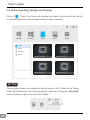
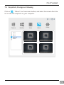
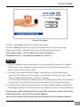
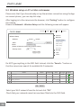
1
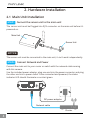
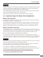
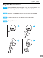
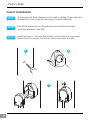
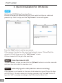
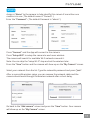
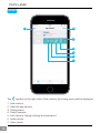
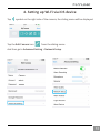
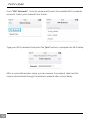
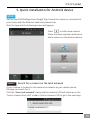
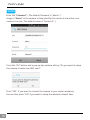
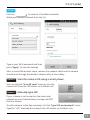
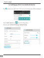
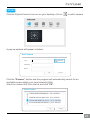
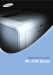
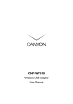
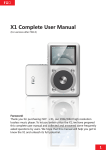
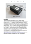
Quick Install Guide
For Covert IP Camera Series
VERSION 2.1
This installation guide provides basic instructions for installing the PLC-128PW
and PLC-129PW covert IP camera on your network.
By following these instructions, you can quickly complete the camera installation
on Android, iOS and computer (Windows or Mac OS).
Get Support
- For technical questions, please email us at [email protected]
You can also access related technical articles on our support website
- For the latest documentation and updates, please visit www.phylink.com
Contents
1. Hardware Overview ................................................................................ 2
2. Hardware Installation ............................................................................ 4
2.1 Main Unit Installation ........................................................................ 4
2.2 Optional steps for Main Unit Installation ........................................ 5
2.3 Sensor Unit Installation for PLC-128 ............................................... 6
2.4 Sensor Unit Installation for PLC-129 ............................................... 9
3. Quick installation for iOS device ......................................................... 10
4. Setting up Wi-Fi via iOS device ............................................................ 13
5. Quick installation for Android device ................................................. 15
6. Setting up Wi-Fi via Android device .................................................... 20
7. Camera installation on PC or Mac ...................................................... 22
8. Access camera via web browser ........................................................ 30
1. Hardware Overview
3
1 2
1. Main Unit
2. Status indicator LED
3. Wi-Fi Antenna
6
7
4
9
7
5
4.
5.
6.
7.
8.
12
Sensor Unit for PLC-129
Bracket for PLC-129
Sensor Unit for PLC-128
Sensor Unit Cable
RJ12 Plug
14
15
13
10
8
11
Mounting Accessories for PLC-128
9. Cover for PLC-128
10. Straight mounting bracket
11. Angled mounting bracket
Line In/MIC
16
18
17
19
I/O
2
CAM
LAN
Reset
DC12V
12.
13.
14.
15.
16.
17.
18.
19.
RJ12 Connector for Sensor Unit
Audio Line In/MIC
Micro SD Card Slot
RP-SMA Connector for Antenna
Ethernet Connector
General I/O Terminal
Power Connector
Reset/WPS Button
Power Connector
Connects to the included DC 12V power adapter.
Reset/WPS Button
This button is used for both WPS and Reset function.
To use the RESET function, press and hold the button for more than five seconds.
Note that all settings will be restored to factory default.
To use the WPS function, ensure the camera has started.
Press the WPS button located on your router and then press the WPS button on
the Main Unit for one second, within 60 seconds.
While connecting, the Status Indicator LED will flash red. Please wait until the
camera reboots, then the Wi-Fi connection will be established.
Note: The WPS push button (also called QSS) option should be enabled on the
router for this function to work.
Status Indicator LED
After Main Unit is powered on, the indicator LED shows a green light then quickly
turns off which means the system is being started. When the indicator LED shows
a green light again, it means the system has started successfully.
The indicator LED flashes green light during data transfer and shows red light for
WPS connection status.
Sensor Unit and Cable
The sensor unit and main unit are connected by a 6 meters (20 ft) cable which will
provide flexibility for remote location placement.
The sensor unit must be connected to the main unit, it can't work independently.
NOTICE
The sensor unit for PLC-128 is not designed for outdoor use. It may only be
installed indoors.
Mounting Accessories
PLC-128 includes various mounting brackets for quick and easy installation.
The sensor unit can be mounted flat or angled on any surface, using the angled
mounting bracket. The camera can also be mounted covertly behind a thin wall,
cupboard, door and etc. With miniature size design it enables easy integration
into any hidden place.
General I/O Terminal
Used to connect the wired alarm devices, such as PIR sensor, detector, siren, etc.
2. Hardware Installation
2.1 Main Unit Installation
STEP1
Connect the sensor unit to the main unit
The sensor unit must be Plugged into RJ12 connector on the main unit before it’s
powered on.
Main Unit
Sensor Unit
NOTICE
The sensor unit must be connected to the main unit, it can't work independently.
STEP2
Connect Network and Power
Connect the main unit to your router or switch with the network cable coming
with this camera.
Use the included power adaptor, plug one end into the power connector and plug
the other end into a power outlet. Once connected and powered, the status
indicator LED should illuminate a constant green.
I/O
LAN
Reset
DC12V
DC power adaptor
Network cable
Router
4
NOTICE
Please note that for initial setup, you need to connect the camera directly to your
router or switch with a network cable. Afterwards, you can set up the wireless
connectivity with the mobile application or web browser.
After completing the wireless setup, remove the network cable and the unit will
switch to the wireless network after a short delay.
Instructions for wireless setup are included later, within this guide.
2.2 Optional steps for Main Unit Installation
Mount the antenna
If using a Wi-Fi Network connection, the provided antenna must be mounted to
the RP-SMA connector on the Main Unit.
Please keep the antenna vertical for better signal strength. A minimum of 3 bar
signal strength is required for HD streaming. Please ensure the required signal
strength is available at the place of installation, prior to installing the camera.
Mount the Micro SD Card
This package dose not included a Micro SD card. Adding a Micro SD card to your
camera will allow you to record footage and motion alerts directly to the Micro SD
card for future review. The recorded files may be reviewed remotely on your
phone / computer when using Phylink App / software.
For a new SD card which has never been used or formatted, you can use the
camera’s format tool to format it. To learn how to format the SD card, please refer
to the user manual or related technical articles on the Phylink support website.
NOTICE
The camera must be powered off before inserting the Micro SD card. The camera
will only recognize the card if inserted before startup.
Every time the card is re-inserted, you will need to turn the power off and then
turn the power on again to let the SD card be recognized.
The camera only supports the FAT32 file system; other formats will not be
recognized. It is recommended to format the Micro SD card via the format tools.
You can download the format tools for FAT32 via the follows links:
www.phylink.com/downloads/download_file/tools/guiformat.zip
Or www.sdcard.org/downloads/index.html
5
Connection Using a PoE Switch or PoE Injector
The PLC-128PW and PLC-129PW can be either connected with the included power
adapter and network cable, or optionally with an Ethernet cable that is connected
to an 802.3af compatible PoE Switch or PoE Injector. With a PoE setup, the
Ethernet cable will transmit both power and data over a single cable eliminating
the need for the power adapter.
2.3 Sensor Unit Installation for PLC-128
The PLC-128 can be mounted in three different ways:
1. Flat on any surface
2. Angled on any surface using the angled fastening bracket
3. Covertly, such as inside a thin wall, cupboard, door, etc.
Flat Surface Installation
STEP1
Mount the sensor unit to the wall or ceiling, using screws and plugs appropriate
for the wall/ceiling material.
STEP2
Snap on the cover.
1
6
2
Angled Surface Installation
STEP1
Mount the angled mounting bracket to the wall or ceiling. Ensure that
the bracket is pointing towards the area to be monitored.
STEP2
Assemble the plate with the screw and align it so the arrows are
vertical or horizontal.
STEP3
Install the Sensor Unit into the plate with the two screws.
STEP4
Snap on the cover.
1
2
3
4
7
Covert Installation
STEP1
Drill a hole with 3mm diameter in the wall or ceiling. If the material is
thicker than 1mm it may be necessary to expand the hole.
STEP2
Pull off the protection on the adhesive and attach the straight
mounting bracket to the wall.
STEP3
Insert the Sensor Unit into the bracket, and fix with the stop screw.
Ensure that the cone of the Sensor Unit is flush with the wall.
1
2
3
8
2.4 Sensor Unit Installation for PLC-129
STEP1
The Sensor Unit for the PLC-129 is IP-67 rated and suitable for
outdoor use.
Outdoor
Indoor
Building wall
A roughly 12mm diameter hole
will be required for sensor unit
cable to pass through
STEP2
Using your mobile device or computer, adjust the bracket to the
desire view.
You may adjust the bracket lock knob and screw by turning
counterclockwise. After adjusting the 2-Axis Bracket (X-Y Axis) to get
the desired viewing angle, tighten the lock knob and screw by turning
it clockwise.
Sensor Unit
Screw
2-Axis Bracket
Lock knob
9
3. Quick installation for iOS device
STEP1
Get the free PHYCAM App from App Store.
Ensure the camera is connected to your router with the Ethernet cable and
powered up. Start the App and the "My Camera" screen will appear.
Press the “Add” button to add a new camera.
If the camera is located on the same local network as your iPhone/iPad, the
camera’s UID will show up on the "Add Camera" screen.
Click on camera’s UID to go to the next step.
Option 1
Scan the camera’s UID
To add a camera to App, you can click the “QRCode” button to scan the camera’s
UID from the UID sticker on the Main Unit.
Option 2
Manually type the UID (Add the camera remotely)
If the camera is not located on the same local network as your iPhone, the App
will NOT find it. To add a camera to the App remotely, click the “Add” button to
type the "UID" manually according to the UID sticker on Main Unit. .
10
STEP2
Assign a "Name" to the camera to help identify this camera if more than one
camera is in use. ( The default name is "Camera". )
Enter the "Password". ( The default Password is "admin". )
Press "Connect" and the App will connect to the camera.
Press "Setup WiFi" to setup the camera to work over wireless.
The camera will search for available Wi-Fi networks around it.
Note: You can skip the “setup Wi-Fi” step and set the wireless later.
Press the "Save" button and the camera will show up on the “My Camera” screen.
Select your network from the list. Type the network’s password and press “Join”.
After a successful wireless setup, you can remove the network cable and the
camera should work through the wireless network after a short delay.
Go back to the “Add camera” screen and press the "Save" button. Your camera
will show up on the “My Camera” screen.
11
STEP3
1
2
3
4
4
5
6
7
Tap
1.
2.
3.
4.
5.
6.
7.
12
symbol on the right side of the camera, the sliding menu will be displayed.
Add camera
View the app version
Sliding menu
Detect camera
Edit Camera, change settings and password
Audio mode
Video mode
4. Setting up Wi-Fi via iOS device
Tap
symbol on the right side of the camera, the sliding menu will be displayed.
Tap the Edit Camera icon
from the sliding menu.
And then go to Advanced Setting > Network Setup .
13
Press “WiFi Networks” , then the camera will search for available Wi-Fi networks
around it. Select your network from the list.
Type your Wi-Fi password and press the “Join” button to complete the Wi-Fi setup.
After a successful wireless setup, you can remove the network cable and the
camera should work through the wireless network after a short delay.
14
5. Quick installation for Android device
STEP1
Get the free PHYCAM App from Google Play. Ensure the camera is connected to
your router with the Ethernet cable and powered up.
Start the App and the following screen will appear.
Press
to add a new camera.
There are three optional methods to
add a camera on the Android device.
Option 1
Search for a camera on the local network
If your camera is located on the same local network as your mobile device,
the App can search for it.
Click the “Scan local network” menu and the camera’s UID will show up on the
"Search camera from LAN" screen. Click on camera’s UID to go to the next step.
15
STEP2
Enter the "Password". ( The default Password is "admin". )
Assign a "Name" to the camera to help identify this camera if more than one
camera is in use. ( The default name is "Camera 0". )
Press the "OK" button and a pop up tips window will say "Do you want to setup
the camera to work over WiFi now?".
Press "YES" if you want to connect the camera to your router wirelessly.
You can also press "NO" if you want to setup the wireless network later.
16
STEP3
Press on
to view list of available networks.
Select your wireless network from the list.
Wi-Fi Setting
None
SSID
Disconnect
PHYLINK
PHYLINK
TP-Link_245416
FAST_11DA2E
phr-002
Type in your Wi-Fi password and then
press "Apply" to save the settings.
After a successful wireless setup, remove the network cable and the camera
should work through the wireless network after a short delay.
Option 2
Scan the camera UID using a smart phone
You can click the “Scan QR code” menu to scan the
camera UID from the UID sticker on the Main Unit.
Option 3
Manually type UID
If your camera is not located on the same local
network as your Android device, the App will NOT
find the camera.
To add a camera to the App remotely, click the “Type UID and pasword” menu.
Type the "UID" manually according to the UID sticker on the Main Unit. .
17
STEP3
1
2
3
4
5
6
7
8
Tap
1.
2.
3.
4.
5.
6.
7.
8.
18
symbol on the right side of the camera, the sliding menu will be displayed.
Add camera
View the app version and get support info
Sliding menu
Detect camera
Edit Camera, change settings and password
Motion detection enable and disable.
Audio mode
Video mode
1
2
1.
2.
3.
4.
5.
6.
3
4
5
6
Quit live video mode
View the recorded Videos and photos
Start recording / Stop recording
Take a snapshot
Enable or disable the microphone of the camera
Enable or disable the speaker
19
6. Setting up Wi-Fi via Android device
Tap
symbol on the right side of the camera, the sliding menu will be displayed.
Tap the Edit Camera icon
from the sliding menu.
And then go to Advanced Setting > Network Setup .
20
Press “Wi-Fi Setting” , then the camera will search for available Wi-Fi networks
around it.
Wi-Fi Setting
SSID
None
Disconnect
PHYLINK
PHYLINK
TP-Link_245416
FAST_11DA2E
phr-002
Press on
to view the list of available networks.
Select your wireless network from the list.
Type in your Wi-Fi password and then
press "Apply" to save the settings.
After a successful wireless setup, remove
the network cable from the Main Unit and
the camera should work through the
wireless network after a short delay.
21
7. Camera installation on PC or Mac
7.1 Camera installation via Camera Live
Phylink Camera Live is a software which makes you find and view your camera
from the Internet easily.
Phylink Camera Live is also a tool that can search for your camera within your
local network. You can configure and view your camera via most popular web
browsers such as FireFox, Internet Explorer, Chrome and Safari.
Phylink Camera Live is provided on the included CD, for both the Windows and
Mac OS.
STEP1
For setup on Windows, insert the provided installation CD into computer's
CD-ROM drive and the installation window will appear.
Click on the "Install Camera Live" button and follow the setup wizard to complete
the software installation.
Note: If the Installation CD program does not start automatically open the CD-ROM
drive and double click on"autorun".
For Mac OS, please install the “Camera Live for Mac” from this Installation CD or
download it from the Phylink website Downloads section.
Install Camera Live
Documents
Exit
NOTICE
The camera must be located on the same local network as your PC/Mac for the
initial connection to be established via the camera search function.
22
STEP2
Click the Phylink Camera Live icon on your desktop, click on
Camera
Multilive
Video
Album
to add a camera.
Setup
A pop-up window will appear as below.
Add Camera
Discover
UID
Password
Name
OK
Cancel
Click the "Discover" button and the program will automatically search for an
available camera within your local network (LAN).
Select the camera UID from the list and click “OK” .
Select Camera
T7S5TH5K2BYRS5BW87Z1 (PLC-325PW)
T5M5TN7U67A4VW87FJ2M (PLC-335PW)
SDS515A6FW5BC7X1UYSU (PLC-233PW)
EVUSJD78JDGHNVBWW76 (PLC-223PW)
OK
Cancel
23
STEP3
Enter "password" ( The default password is "admin" ).
And then enter a name for your camera.
Click on "OK" to save.
Add Camera
UID
C3S998FY5G639HPGU7T1
Discover
Password
Name
Home
OK
After a few minutes the chain icon
will turn green
the camera is online and connection is established.
Cancel
, which indicates that
If the camera fails to connect, please check both the hardware connections of
your camera and your Internet connection.
Upon completion of the above steps, you have completed the camera installation
on your computer and you can view the camera now.
NOTICE
The camera must be located on the same local network as your computer for
connection to be established.
If the camera is not located on the same local network as your computer, the
Camera Live program will NOT be able to find the camera. You can manually type
the camera’s UID according to the sticker on the Main Unit.
24
7.2 Play, Delete and Modify cameras
Click on
“menu” button to play/delete/modify camera.
Click on
”play” button for live viewing. Or you can double click on
the camera preview for live viewing.
Click on
”delete” button to delete a camera.
In the lower left corner of camera preview, there is a chain icon which use to
indicate camera’s connection status.
CVZMNUX5A6T2K5VM8RE7
Camera
This icon indicates that the camera is online and the connection
is established.
This icon indicates that the camera is disconnected.
If this state continues, please check the UID and password you entered,
and check if your Internet connection is working.
Also check the hardware installation of your camera.
25
Click
”play” button or double click on a camera preview to enter the live
viewing mode. You can perform various operations with the Play Control Panel
at the bottom of live viewing window.
Camera
Multilive
Video
Album
Setup
1920x1080 8FPS 1.3Mbps
Live Viewing Window
Play Control Panel
Take a snapshot
Record video
Speak talk back
Zoom in display ratio
Zoom out display ratio
Full screen viewing
Back cameras preview
Mute
Volume control bar
26
7.3 Muliti-viewing on one screen
Click on
"Muliti-Live" button from main toolbar, click selection icon
then the Select Camera window will pop up as below.
Video
Multilive
Select Camera
Home
Office
Album
Setup
School
Bedroom
OK
Cancel
All cameras will be listed. Select the right cameras for Muliti-viewing on one screen.
Click a camera preview to add it to the Muliti-viewing window, the camera preview
will have a blue border. Clicking the camera preview again will remove the selection
and the blue border will disappear.
Once you have made your selection click on "OK" to save.
Camera
Multilive
Video
Album
home
office
bedroom
school
Setup
If you wish to hear the sound from
a camera, you just need to click the
live viewing window of that camera.
A blue border will highlight your
selection. The available audio is
limited to a single camera selection;
there is no support for multiple
audio streams.
27
7.4 Video recording, Storage and Viewing
Click on
“Video” icon from main toolbar, and select the camera from the list
to view and play back the recorded video on your computer.
Camera
Multilive
Video
Album
Setup
Home
Office
Bedroom
school
20140206_102606.mov
20140208_102605.mov
20140108_092905.mov
20140108_092903.mov
NOTICE
The recorded videos and snapshots will be saved to the "Camera Live" folder
under My Documents. You can also specify a path by clicking the "Save Path"
menu at the top right corner of main toolbar.
Album
28
Setup
7.5 Snapshots, Storage and Viewing
Click on
“Album” icon from main toolbar, and select the camera from the
list to view the snapshots on your computer.
Camera
Multilive
Video
Album
Setup
Home
Office
Bedroom
school
20140206_102606.jpg
20140208_102605.jpg
20140108_092905.jpg
20140108_092903.jpg
29
8. Access camera via web browser
8.1 Login to your camera via a browser
Phylink Camera Live is a tool that can search for your camera on the local network.
You can configure and view your camera via most web browsers such as FireFox,
Internet Explorer, Chrome and Safari.
Start the Phylink Camera Live and click on
icon from the main toolbar.
Click the "Search" button, the program should automatically find the camera
in your local network (LAN).
Sometimes the program may take a few minutes to find your camera, so if your
camera isn’t displayed, wait a few minutes before clicking “Search” button again.
Multilive
Camera
Album
Setup
Name
Location
IP
Port
PLC-128PW
Network Camera
Default Location
192.168.168.39
80
Model
1
Video
MAC
P2P UID
0:e0:4b:c2:8f:64 T5M5TN7U67A...
2
PLC-335PW
Network Camera
Default Location
192.168.168.56
80
0:e0:4b:c2:6e:22 SR6MJ87HJKF...
3
PLC-233PW
Network Camera
Default Location
192.168.168.77
80
0:e0:4b:b9:11:68 EVFG78KHUW...
4
PLC-223PW
Network Camera
Default Location
192.168.168.75
80
0:e0:4b:c6:23:c4 VDF45G8IPK3...
Search
Browser
Clear
Setup
Select the camera from the camera list and it will be highlighted.
Click the "Browser" button and the camera’s login page will appear.
NOTICE
1. If you cannot search for the camera, please check the connections of the
camera and computer. Please refer to Hardware Installation section.
2. If you need to configure the IP address of the camera, select the camera from
list and click the “Setup” button at the lower right corner of the window.
30
Covert Network Camera
PLC-128PW
720P
Camera login page
Click the "Live Video" button to view the live video.
Click the "Setting" button to setup your camera with its various settings.
When prompted for authentication, use the following information.
User Name: admin ( The default User Name is "admin". )
Password: admin ( The default password is "admin". )
NOTICE
1. Phylink Camera Live can only search for a camera within your local network.
That means your computer and your camera need to be connected to the
same router via Ethernet or Wi-Fi.
2. To access the camera via the browser remotely, you have to know your
camera's URL address. You can login to the camera locally (over your home
/office network) and browse to Setting > System.
On the system information page you can find the Internet URL of the camera.
You can type this URL into your browser and access the camera remotely.
3. To play the live video from the camera, the web browser needs to install the
flash player plug-ins for Chrome/Safari or ActiveX Control for Internet Explorer.
To learn more about accessing the camera from a browser, please refer to the
Technical Articles - Access Camera from Browser.
You can find related technical articles on Phylink technical support website.
31
8.2 Wireless setup on PC or Mac via browser
Please note that if you have already set up the wireless connection using the App
on a smart phone , you can skip this step.
After logging in to the camera via the browser, click "Setting" button to configure
the camera.
Browse to Network > Wireless Setup and the following screen will appear.
Live View
Wizard
System
Reboot
Support
Camera
Wireless Setup
Network
Wireless:
Enable
Disable
Wireless Setup
Wirelessnc
SSID:
Infrastructure
Mode:
(Select infrastruture mode using wireless router.)
Security mode:
Search...
TCP/IP Setup
DDNS Setup
UPNP Setup
P2P Setup
Off
Storage
Apply
Test
Task
Tools
Do NOT type anything in the SSID field. Instead, click the "Search..." button so
that the camera can search for available Wi-Fi networks.
Mode
Channel
Auth
Encrypt
wirelessnc
Infrastructure
9
OPEN
NONE
AES
SSID
TP-LINK_4B8C68
Infrastructure
1
WPA2PSK
FAST_3AC1FE
Infrastructure
13
WPA2PSK
AES
Tenda_0B0458
Infrastructure
13
WPA2PSK
AES
OK
Cancel
Select your Wi-Fi network from the list and click "OK".
Check that your network name has now been filled into the SSID field.
32
Signal
Live View
Wizard
System
Support
Reboot
Camera
Wireless Setup
Wireless:
Network
Enable
Disable
TP-LINK_4B8C68
SSID:
Infrastructure
Mode:
(Select infrastruture mode using wireless router.)
Security mode:
Encryption type:
Wireless Setup
Search...
TCP/IP Setup
DDNS Setup
UPNP Setup
P2P Setup
WPA2PSK
Storage
AES
Task
WPA Key:
Re-type WPA Key:
Tools
Apply
Test
Do NOT change any of the settings ( SSID, Mode, security mode, Encryption type )
Enter the "WPA Key".
Note: WPA Key is also known as the wireless key or password and they are case
sensitive.
Click the "Apply" button and "Wireless setup accepted successfully" message
will be displayed.
Now you should click the "Test" button to check if all the information about the
wireless was entered correctly.
If the test reports "Success!" you can remove the network cable and the camera
should work through wireless network after a short delay.
For more advanced settings, (such as Record, Task Management,
Motion Detection, Alarm Action, Video Quality and more) please
read the User Manual on the installation CD included with this
package or download from the Phylink support website.
33
Technical support
If you encounter any problems, do not return the product to the store
If you have any questions please email us at [email protected]
All Phylink hardware products have a one year warranty.
We offer free technical support within warranty time.
If you purchased this product from us or an authorized retailer,
you are eligible for priority email based technical support.
Can I speak to someone?
We address most support inquiries through email. One of our qualified technicians
will help you as quickly as possible. Most issues can be resolved much quicker by
email than by phone. Especially for the special technical problems from customers,
email support can provide pictures, video and text points which can not be
provided by phone.
If you are totally stuck, we can make an appointment
for tech support tutorial via one-on-one telephone.