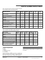
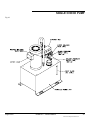
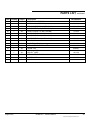
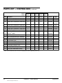
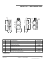
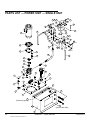
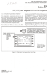
1
Automatic Wheel Restraint (In-Ground Mounted) This manual applies to all wheel restraints manufactured August 2013 and later with serial number 61087800 and higher. Do not install, operate or service this product unless you have read and understand the Safety Practices, Warnings, and Installation and Operating Instructions contained in this User’s Manual. Failure to do so could result in death or serious injury. User’s Manual Installation, Operations, Maintenance and Parts Part No. 6004921H Table of contents Introduction..................................................................2 Safety Signal Words....................................................2 Safety Practices..........................................................3 Installation...................................................................4 Trailer Presence Sensor - Optional........................... 13 Start-Up And Test......................................................14 Troubleshooting.........................................................17 Operating Instructions...............................................21 Planned Maintenance................................................24 Heat Tracer Installation.............................................25 Lights/ Alarms Status Table.......................................27 Specifications............................................................28 Wiring Diagrams........................................................29 Hydraulic Schematic Single Chock Pump................................................35 Dual Chock Pump..................................................36 Parts List ..................................................................37 Parts List — Control Box...........................................40 Parts List — RED/GREEN Light................................ 43 Parts List — Power Unit — Single Unit..................... 44 Parts List — Power Unit — Dual Chock.................... 47 Warranty....................................................................51 Distributor Information...............................................52 Introduction Welcome and thank you for buying this wheel restraint from 4Front Engineered Solutions, Inc. This User’s Manual contains information that you need to safely install, operate and maintain the wheel restraint safely. It also contains a complete parts list and information about ordering replacement parts. Please keep and read this User’s Manual before using your new wheel restraint. This manual covers the Serco® Universal Truck-Chock™ and the Kelley® AUTO CHOCK® wheel restraints. safety signal words You may find safety signal words such as DANGER, WARNING, CAUTION or NOTICE throughout this Owner’s Manual. Their use is explained below: This is the safety alert symbol. It is used to alert you to potential personal injury hazards. Obey all safety messages that follow this symbol to avoid possible death or injury. Indicates an imminently hazardous situation which, if not avoided, will result in death or serious injury. Indicates a potentially hazardous situation which, if not avoided may result in minor or moderate injury. Indicates a potentially hazardous situation which, if not avoided, could result in death or serious injury. Notice is used to address practices not related to personal injury. 2 6004921H — Wheel Restraint ©2013 4Front Engineered Solutions, Inc. August 2013 Safety practices INSTALLATION, MAINTENANCE AND SERVICE Read these safety practices before installing, operating or servicing the wheel restraint. Failure to follow these safety practices could result in death or serious injury. If you do not understand the instructions, ask your supervisor to explain them to you or call your local distributor. OPERATION Use restricted to trained operators. Use by untrained people can cause property damage, bodily injury and/or death. Your supervisor should teach you the safe and proper way to use the wheel restraint. Read and follow the operating instructions on page 21 before use. DO NOT USE THE WHEEL RESTRAINT IF IT IS NOT WORKING RIGHT. Tell your supervisor it needs repair. Before restraining a vehicle check that proper clearance is available under the vehicle throughout the full range of chock motion. Do not operate the restraint with equipment, material, or people directly in the path of the restraint. Keep hands and feet clear of the chock mechanisms and guide path at all times. Stay clear of the restraint when it is moving. Do not load or unload any vehicle unless you make certain the wheel restraint has securely chocked the vehicle’s rear wheels and set the brakes. If the wheel restraint does not chock the vehicle’s tire for any reason, BE CERTAIN TO MANUALLY CHOCK THE VEHICLE WHEELS BEFORE LOADING OR UNLOADING. Before doing maintenance or service be certain that the STOP push-button is pushed in, and the power is disconnected and properly tagged or locked out. Failure to follow these safety practices may result in death or serious injury. If the wheel restraint does not operate properly using the procedures in this manual, BE CERTAIN TO MANUALLY CHOCK THE VEHICLE WHEELS BEFORE LOADING OR UNLOADING. Call your local distributor for service. Place barricades around pit on dock floor and drive while installing, maintaining or repairing trailer restraining device. Do not stand in the driveway between the dock and a backing vehicle. Do not use the wheel restraint as a step. Keep hands and feet clear of guide tracks and moving parts at all times. All electrical troubleshooting and repair must be done by a qualified technician and meet all applicable codes. Disconnect the power and properly tag or lock off before doing any electrical work. If it is necessary to make troubleshooting checks inside the control box with the power on, USE EXTREME CAUTION! Do not place fingers or uninsulated tools inside the control box. Touching wires or other parts inside the control box could result in electrical shock, death or serious injury. Before chocking wheels or engaging vehicle restraint, dump air from air ride suspensions and set parking brakes. August 2013 6004921H — Wheel Restraint 3 ©2013 4Front Engineered Solutions, Inc. INSTALLATION Before installation read and follow the Safety Practices on page 3. Failure to follow these safety practices could result in death or serious injury. READ AND FOLLOW THE OPERATION INSTRUCTIONS IN THIS MANUAL BEFORE OPERATING THE WHEEL RESTRAINT. If you do not understand the instructions, ask your supervisor to teach you how to use the wheel restraint. Improper installation of the wheel restraint could result in death or serious injury to dock workers or other users of the wheel restraint. Place barricades around pit on dock floor and drive while installing, maintaining or repairing trailer restraining device. Be certain bystanders in the driveway stand clear when wheel restraint is operated. Be certain to follow the installation instructions in this manual. preliminary checks 1. Confirm the site survey done prior to order. Follow the Site Survey (Form #10-763) instructions and requirements. This survey will confirm or establish: unit location and elevation requirements, drainage system and location, power unit location, control box and light locations, and finally, location of hydraulic and electrical runs. This site planning will be done best with the participation of all involved parties, (Contractor, Installer, Electrician, End User, etc.). The resulting survey will be the map for laying out the installation in the following steps. Careful planning is the key to trouble-free installation. 2. Locate and mark the centerline of the doorway, or dock position, onto the drive according to the following steps. See Fig. 1 on the following page. 2.1Locate and mark the centerline of the dock position onto the dock surface. Extend the marking down the face of the dock, to the driveway, with a plumb bob or level. 4 2.2Project the centerline of the dock position out onto the driveway by marking the wall or dock face, at dock level, 5 ft. on either side of the centerline of the dock position. Hold one end of a 50 ft. tape measure at the right side mark and pull the tape out to 35 ft. Sweep an arc across the centerline of the position at 35 ft. and hold the end of the tape measure at the left side mark. Sweep another 35 ft. arc from the left side. The intersection of the two arcs is the centerline of the dock position out on the driveway. 2.3Pull a string line tight between the centerline of the dock position at the base of the dock, and the intersection marked above. Use the string as a guide and mark the driveway. This line is the centerline of the dock position. 3. Locate and mark the centerline of the housing onto the drive by transferring a line 38" to the right (as you face the dock) of the previously marked centerline. Be sure to mark the centerline up onto the dock face or wall for future reference in placing the restraint into the excavation. See Fig. 1 on the following page. 4. Mark the boundaries of the excavation for the housing by transferring a line 15" to each side of the previously marked centerline of the unit and marking an end line for the excavation, 32 ft. from the dock face or wall. See Fig. 1 on the following page. 5. While all of the previous marking may have been done in chalk, loggers pencil, etc., some of the markings should now be traced with paint so that they are not washed away before the excavation and installation are completed. Areas that should be paint marked are: the boundaries of the excavation, the position centerline reference marks, and the chock centerline reference marks. See Fig. 1 on the following page. 6. Mark the excavation requirements for the drainage system as determined in the site survey of step #1. 6004921H — Wheel Restraint ©2013 4Front Engineered Solutions, Inc. August 2013 INSTALLATION, continued Fig. 1 5' 5' C L 38" 16" (24") CL Dock position Position centerline reference marks 35' 35' 32' Chock centerline reference marks 15" 15" August 2013 Boundaries of excavation 6004921H — Wheel Restraint 5 ©2013 4Front Engineered Solutions, Inc. INSTALLATION, continued site preparation NOTE: The specific construction of the driveway will greatly dictate the methods used in excavation of the site. A careful review of the building plans and improvements will help in the planning of the wheel restraint installation. If the specific construction of the driveway is not known, before excavation begins, installation may be delayed if it is found that additional equipment or materials are required. Underground services in the vicinity (water, sewer, electrical, telephone, etc.) must be identified prior to excavation. Consult building plans and local utilities during the planning stages of the project. Many utility companies offer free location services that can be called on fairly short notice (several days). Failure to properly identify underground services in the vicinity can lead to death or serious injury. 1. Saw cut the outline of the excavation, the drainage system, and the hydraulic and electrical runs into the driveway surface, dock face and floor. 6. Assemble drain tile, pipe and fittings into the areas of the excavation that will be filled with concrete. NOTE: Drainage systems are typically regulated by various local agencies. Local codes and regulations for sizing, layout and discharge must be followed. Failure to adhere to local requirements may result in expensive delays while compliance is achieved and verified. 7. Double check the position of drain components to assure that they are in a position compatible with the site layout and plans. Fill excess voids around drain components with gravel, taking care to tamp around components and eliminate any voids. 8. If the housing area was excavated deeper than 16", fill the excavation to a depth of 16" with gravel. Be sure to tamp the gravel in all areas and eliminate voids. 9. Compact the gravel carefully across the entire surface of the bottom of the excavation. Vibratory compaction is best if such equipment is available. 2. Break up the surface layer(s) of the drive in the area of the excavation with a jack-hammer. Depending on the depth of the surface layers, the surface in the area to be excavated can also be saw cut into manageable-sized pieces for removal. 3. Remove the surface material and excavate the area for the housing with a back-hoe or similar piece of equipment. The excavation for the housing should be cleared to a depth of 16" (or 24" if a layer of crushed stone is to be placed as a bed for the concrete). Improper excavating and removal of material can leave the wheel restraint with insufficient support. Remove all loose material from the bottom of the excavation and leave the bottom of the excavated pit undisturbed. Failure to do so can result in settling of the foundation which could hinder operation or cause damage to the unit. 4. Remove all loose material from the bottom of the excavation. 5. Excavate driveway, dock and floor for drainage system, hydraulic and electrical runs. 6 6004921H — Wheel Restraint ©2013 4Front Engineered Solutions, Inc. August 2013 INSTALLATION, continued unit preparation 1. Prepare the housing for installation by clamping (2) 4 ft. long cross braces (3" x 3" x 1/4" angle or equivalent) to the top flanges of the housing. These braces will be used to support the housing over the excavation and anchor the housing against shifting or floating pressure while concrete is poured around the housing. See Fig. 2. NOTE: The position of the cross braces should be such that the trailer restraint is suspended at the desired elevation. For a level driveway, or a flat drive that is not necessarily level, the cross braces will always suspend the housing at drive level. For a driveway with a split decline, concave, or convex surface, the cross braces should be positioned to equalize the elevation differences. If there are any questions as to the appropriate positioning of the wheel restraint, contact your local representative for assistance. 3. Install drain fittings into the bottom of the housing. The position, size, and style of fitting depend on the drainage system to be used but should not be less than 2" in dia. and must never project up into the bottom of the housing. Install strainers over the top of the drains. See Fig. 2. 4. See that the spreader plates are properly repositioned in the track area of the housing. These spreaders maintain the track spacing against the pressure of the concrete while it is poured and until it sets. See Fig. 2. 5. See that all cover plates are repositioned and fastened in place. This will help to maintain the track spacing and help to prevent concrete from getting into the housing during the pour. 2. Install one 4" dia., wide sweep conduit elbow into the dock end of the housing. This elbow will be used for passage of hydraulic hoses and heat tracer cables (if so equipped). Install one 3/4" dia. conduit elbow into the dock end of the housing. See Fig. 2. 2.72 Fig. 2 7' “A” “A” 6" max. Spreader plates 4.90 Lifting chain attaching points 5" Drain View “A-A” “B” 7' Clamps Drain 4' August 2013 View “B-B” “B” 6004921H — Wheel Restraint 7 ©2013 4Front Engineered Solutions, Inc. INSTALLATION, continued unit placement Inadequate lifting equipment or practices can cause a load to fall unexpectedly. Make sure the lifting chain or other lifting devices are in good condition and have a rated capacity of at least 3000 lbs. for the lifting angle used. Never allow anyone to stand on or near the restraint when it is lifted or positioned. Stand clear of the vehicle restraint when it is positioned. Failure to follow this warning could allow the restraint to fall, tip, or swing into people, resulting in death or serious injury. 1. Lift the housing using suitable straps or chains attached at points provided (Fig. 2), and place the housing into the pit, suspended from the previously installed cross-braces. See Fig. 3 on the following page. 2. Center the housing in the excavation by aligning the center of the housing with the chock centerline reference marks. 3. Position the end of the housing 6" away from the dock face. This will properly position the travel of the chock with respect to the dock. 4. Check that the unit is level with the drive. Shim under the cross braces if necessary to achieve the desired elevation. 5. Secure the housing in place so that it remains stationary and properly positioned throughout the pouring and setting of the concrete. The housing must be secured in position during the pouring of the concrete. This can be done by lagging the cross braces into the undisturbed driveway surface, by blocking and/or weighting the housing directly, or by blocking and/or weighting the ends of the cross braces. Failure to adequately secure the housing during the concrete pour may result in an improperly positioned restraint. Improper positioning of the restraint may result in inadequate drainage of the housing or improper engagement of vehicle wheels. 6. Position and attach all drain connections. See that they are secure enough to retain their position and integrity during the pouring and tamping of the concrete. Some blocking may be necessary. 8 7. See that there are no areas of the drainage system that can be plugged by the concrete when it is poured. Seal these areas as necessary to assure proper drainage after the completed installation. 8. Remove bolted on lifting lugs. Concrete can now be poured. If the excavation has been made according to the accompanying dimensions, approximately 3-3/4 cubic yards have been excavated. The housing displaces approximately 1-1/4 cubic yards. This leaves approximately 2-1/2 cubic yards to be filled with concrete. However, be sure to provide for any additional concrete necessary for feathering to the drive or spot fills. The entire concrete pour must be completed in one pass in order to assure a solid foundation for the wheel restraint. 9. Begin pouring concrete into the excavation. Start at one end and carefully fill and tamp the concrete into the cavity under the housing. “Vibrating” the wet concrete is a good way of eliminating air pockets and assuring a solid foundation. Periodically place reinforcing rods into the concrete under the housing. See Fig. 3 on the following page. 10. When an area underneath the housing is filled and well vibrated, place reinforcing rod next to the housing and continue to fill the cavity up the sides. Be especially careful to flow the concrete into and around the anchor straps on the side of the housing. These will lock the housing to the concrete and assure a solid connection of the housing to the drive. 11. Continue from one end of the unit to the other, filling underneath, periodically placing reinforcing rods, and filling up along the sides of the housing. All the while the concrete should be vibrated to remove air pockets and feathered to the drive at the surface. 12. At this point the installation of the housing into the drive is complete. Remove the cross braces and clamps and feather any depressions left by the clamps. 13. Allow the concrete to cure for at least 4 days before vehicle traffic is allowed on the unit. Follow the recommendation of the concrete supplier if different than 4 days. 6004921H — Wheel Restraint ©2013 4Front Engineered Solutions, Inc. August 2013 INSTALLATION, continued Fig. 3 “A” 38" ref. 6" “A” Dock face Reinforcing rods 6" Chock centerline reference marks Concrete anchors 7" C L Dock position August 2013 C L Area for concrete 7" Chock Undisturbed subsoil Crushed stone Section “A” - “A” 6004921H — Wheel Restraint 9 ©2013 4Front Engineered Solutions, Inc. INSTALLATION, continued final installation Fig. 4 NOTE: The following instructions cover the standard power supply and controls supplied with the Trailer Restraint. If special controls, features or interlocks are part of this installation, refer to the manuals or prints related to those features for specific instructions. Hydraulic connections Electrical connections Filler cap Level sight glass 1. If the hydraulic power supply is to be wall mounted, secure the mounting bracket to the wall with suitable anchors. 2. Position the hydraulic power supply in the chosen location. Be sure to orient the unit so that the side with the level sight glass is clearly visible and the filler cap on top is easily accessible. Six (6) inch clearance between the wall and hydraulic power supply is required to allow for hose routing and hook-up on the side where the hydraulic connections are made. See Fig. 4. 3. If the unit is wall mounted, secure the unit to the bracket through the holes provided in the base. If the unit is floor mounted, it can be lagged to the floor if so desired. Fig. 5 4. Mount the control panel on drivers side of the dock so that the communication lights are visible to the fork truck driver. Mount the outside communication lights/alarm and sign so that they are visible to the vehicle driver. Refer to the installation drawing for recommended dimensions. Make sure the Red light is on top and the Green light on the bottom when the light assembly is mounted. See Fig. 5. 10 6004921H — Wheel Restraint ©2013 4Front Engineered Solutions, Inc. Mount control box on left side of door opening. Mounting hardware by others. Eye level, approx. 60" August 2013 INSTALLATION, continued NOTE: The chock motion alarm assembly must be mounted in the area of the chock. The chock motion alarm assembly must be mounted in the area of the chock. Failure to mount the alarm in close association with other dock and restraint components may reduce its effectiveness which could result in death or serious injury. The motion alarm assembly is designed and controlled to sound whenever the chock is in motion. Each alarm is strictly associated with a single unit, its mounting position must be such to maintain that association at installation. 5. Mount the vehicle driver caution sign immediately below the light and alarm assemblies. This sign must also be clearly visible in the driver’s side mirror. See Fig. 6. Fig. 6 hydraulic installation 1. Route the hydraulic hoses that come coiled in the housing through the conduits and to the hydraulic power supply. Dirt or debris in the hydraulic system can hamper proper operation of the restraint. Do not allow dirt or debris to enter the hoses. If the hoses do become contaminated, remove the hoses and clean them by blowing compressed air through the hose from the clean end. 2. One of the two hoses is shorter and has a male fitting. Connect this hose to the C2A port (release) on the valve block. 3. Connect the hose with the female fitting to the C1A port (chock) on the valve block. 4. Check all hydraulic fittings and connections to see that they are properly connected and tight. Do not over-tighten. Motion alarm (mounted to top of outside light assembly on driver’s side) 24V compact lights/alarm and sign (supplied by 4Front) (installed by others) Mount sign below light. Keep light and sign in one area to concentrate visual warning display Allow for door seals (approx. 15") 90" Centerline of light in line with vehicle mirror 5. Remove hydraulic hose slack by coiling excess hose between reservoir and wall. Do not leave slack hose in wheel restraint pan. August 2013 6004921H — Wheel Restraint 11 ©2013 4Front Engineered Solutions, Inc. INSTALLATION, continued electrical installation Fig. 7 Before installation read and follow the Safety Practices on page 3. Failure to follow these safety practices could result in death or serious injury. Before doing any electrical work, make certain the power is disconnected and properly tagged or locked off. All electrical work must be done by a qualified technician and must meet all applicable codes. If it is necessary to make troubleshooting checks inside the control box with the power on, USE EXTREME CAUTION. Do not place fingers or uninsulated tools inside the control box. Touching wires or other parts inside the control box may cause electrical shock, death or serious injury. High voltage power wires should be run in separate conduit from low voltage control circuit wiring. 1. Wire the outside lights and alarm assembly to the control box according to the wiring diagram shipped inside the control box. Typical wiring diagrams have been provided in this manual for reference. See pages 30-34. 2. Wire the hydraulic power supply’s electrical box to the control box according to the wiring diagram (shipped inside the control box), and Fig. 7. A typical wiring diagram has been provided in this manual for reference. See pages 30-34. 3. If the Dual Pump option is desired, refer to the explanation on page 29 and the connection diagram on page 32 and 33 for required field wiring. 4. The Leveler Stored (terminals 24V and 10) and Door Closed (terminals 24V and 9) signals are jumpered at the factory. Their functions are to prevent the release of the restraint while the leveler is not stored and the door is not closed. Install input switch devices as necessary to use these features. Reference drawing 6001045 for details. 5. Automatic snugging can be enabled by placing a jumper wire from 24V to 12. This feature is disabled from the factory. See pages 29-34. 6. A VSL fault override for purposes of controlling the lights in an interconnected system can be implemented by terminating the appropriate signal wiring to input 11 of the PLC. This wiring will originate at the coupled VSL control panel. Reference drawing EL3053 for details. Junction box Dual chock pump units only Chock solenoid Release solenoid Release pressure switch Valve block Chock pressure switch Check valve with single chock pump. Interlock solenoid valve with dual chock pump. 7. Terminals R13 and R14 provide a leveler interlock to the coupled leveler control panel. Reference EL3053 for details. 8. Check the control box for the voltage supplied. The control box is factory wired for the voltage specified on the order. The label inside the control box will show the pre-wired voltage requirements. 9. Check the drive motor for voltage requirements (it may accept dual voltage). The drive motor’s voltage(s) are stamped into the nameplate on the motor. NOTE: A fused disconnect is required for each Trailer Restraint as a means of disconnecting and limiting incoming power to the control box. This disconnect is supplied by others unless specifically ordered from 4Front Engineered Solutions, Inc. For correct disconnect fuse size “X”, and fuse type, refer to the charts and wiring diagram for the proper voltage on page 34. 10. For vehicle presence sensor (optional) installed termination, see schematic included in panel. 10.1 The sensor is a 4 wire device. First terminate the positive lead (brown wire) to any "C" terminal on the input board. 10.2 Terminate the negative lead (blue wire) to any "0V" terminal in the panel. 10.3 Terminate the load lead (black wire) to the terminal specified in the job specific wiring schematic. 10.4 Tape (insulate) the unused white wire. 11. Verify that both steps 8 and 9 above match the voltage 12 6004921H — Wheel Restraint ©2013 4Front Engineered Solutions, Inc. August 2013 INSTALLATION, continued specified on the order. If they do not, contact your local representative for assistance. 12. Check that the fused disconnect for this installation is a lockable type and meets all applicable electrical and safety codes. Fig. 8 Building wall 13. Mount the fused disconnect near the control box and wire three phase power to it from an available power source. Top View 14. Check voltage at the disconnect. It must match voltages checked in steps 9 and 10 above. Note: Rotate head 5° from center 15. Run three phase power wires from the fused disconnect to the control box. 3-4477 16. Make connections to heat tracer if so equipped per steps 9-13 on page 26. 17. The wheel restraint is now ready for start-up and test. Be sure to securely close the control box enclosure at this time. Trailer Present sensor (Optional) The trailer present sensor senses a vehicle at the dock and transmits a signal to the control panel. This turns on the panel face AMBER light. Mount the sensor. See Fig. 8. Ensure the sensor's logic switch is set to L/O (Light Operate). The switch is located on the top of the sensor under a plastic cover. Wire the switch. Wire the sensor into the panel per the per the job specific schematic located in the panel. Test for proper operation as per below.. OPERATIONS No Trailer Present • Inside lights display Solid RED outside display GREEN. Trailer Arrives • Inside lights switch to Solid AMBER and RED, outside lights continue to display GREEN. Operator engages vehicle restraint • Inside lights switch to Solid GREEN, outside lights switch to display RED. Center line of door opening Conduit to control panel Front View Building wall 34"- 48" ref. 315-370 C E 1/2" rigid conduit with 15° bend 14' - 6' minimum above grade Side View Operator releases vehicle restraint • Inside lights switch to Solid AMBER and RED, outside lights continue to display GREEN. Trailer Departs • Inside lights display Solid RED outside display GREEN. August 2013 6004921H — Wheel Restraint 13 ©2013 4Front Engineered Solutions, Inc. START-UP AND TEST Do not service this product unless you have read and followed the Safety Practices, Warnings, and Operation instructions contained in this manual. Failure to follow these safety practices could result in death or serious injury. Before doing maintenance or service push “STOP” push-button in. Remove power at the fused disconnect during all electrical or mechanical service. Disconnect must be properly locked out during maintenance or service of equipment. Failure to disconnect power may result in death or serious injury. Before putting the restraint into service, there are preparations and functional checks that must be made. They are: 1) Checking motor rotation. 2) Bleeding air from the hydraulic cylinder and lines. 3) Checking chock travel. 1. Remove spreader plates from the track/rail area. The plates sole purpose was to maintain track spacing during installation. They may now be discarded. The following steps 2-4 will be taken with the power on and the control box open. Only qualified electrical personnel should access the control box while under power. 2. Open the control box and activate the system by turning on the power at the fused disconnect. 3.Verify component hook-up a follows: 3.1 Note the condition of the control panel’s indicator lights. The RED light will likely be flashing upon initial power up. This indicates a pre-operational condition. If it is solid RED proceed to step 5. 3.2 Pull the STOP button out, then press and hold the RELEASE button. The motor should run long enough to bring RELEASE pressure up which will reset the system and illuminate the panel’s RED light solid. If successful, proceed to step 5. 14 6004921H — Wheel Restraint ©2013 4Front Engineered Solutions, Inc. August 2013 START-UP AND TEST, continued 3.3 If the chock is stored and the motor continues to run, press the STOP button to stop the motor and perform the following checks: 3.3.1 Verify proper operation of the valves for the RELEASE function. While the motor is running, check for magnetism at the solenoid coils. SV2 should be energized. If the shared pump option is being employed, SV3 must also be energized. SV1 must NOT be energized. If solenoids are not properly energized, refer to the troubleshooting section of this manual to determine the cause of the malfunction. 3.3.2 If SV2 and SV3 (if applicable) are properly energized while SV1 is NOT energized and the chock moves toward the chocked position, swap hydraulic hoses at C1A and C2A and repeat step 3.2. Allow enough time while holding the RELEASE button for the chock to return to its stored position. 3.3.3 If the chock is seated in the stored position and does not move, monitor for a RELEASE pressure indication at the PLC (input 3). If pressure is not indicated, refer to the electrical troubleshooting section of this manual to determine the cause of the pressure switch’s failure to indicate pressure. Motor phasing may be incorrect causing the motor to run backwards which will affect this condition. If phasing errors are suspected, proceed to step 4 to change the motor’s phase then repeat step 3.2. 4. Reverse the motor rotation (if necessary) as follows: 4.1Disconnect power. 4.2Reverse the motor wiring by switching any two of the three motor wires connected to the overload relay: T1, T2, and T3. 4.3Reapply power. August 2013 6004921H — Wheel Restraint 15 ©2013 4Front Engineered Solutions, Inc. START-UP AND TEST, continued 5.Verify CHOCK and RELEASE functions a follows: 5.1 With the chock stored and the inside RED light illuminated solid, ensure the STOP button is out and press the CHOCK button. The chock should move toward the chocked position and the inside and outside RED lights will flash. The motion alarm should sound while the motor is running. If the chock fails to move, press the STOP button and refer to the troubleshooting section. 5.2 The chock will travel full stroke in approximately 30 seconds and issue a Truck Not Found alert indicated by the RED and AMBER lights flashing together with an audible fault alarm pulse sound. 5.3 With the chock in the chocked position (cylinder fully extended), ensure the STOP button is out and press the RELEASE button. The chock should move toward the stored position and store itself. The time required to store the chock should not be greater than 40 seconds. Once stored, the motor will stop, the inside RED light will illuminate solid and the outside GREEN light will flash. Refer to the troubleshooting section if errors occur. 6. Verify OVERRIDE function as follows: 6.1 With the chock in any position (except a valid hitched condition) rotate the OVERRIDE selector. The inside GREEN and AMBER lights will illuminate solid. If the fault alarm is sounding, it will be silenced. 6.2 Press RELEASE to clear the OVERRIDE condition. Note: interlock conditions must be met prior to clearing this mode, i.e. Door Closed and Leveler Stored. 7. Check the outside lights. With the chock retracted, the green light should be flashing and the red light should not be illuminated. 16 6004921H — Wheel Restraint ©2013 4Front Engineered Solutions, Inc. August 2013 TROUBLESHOOTING Before doing maintenance or service push “STOP” push-button in. Remove power at the fused disconnect during all electrical or mechanical service. Disconnect must be properly locked out during maintenance or service of equipment. Failure to disconnect power may result in death or serious injury. Do not service this product unless you have read and followed the Safety Practices, Warnings, and Operation instructions contained in this manual. Failure to follow these safety practices could result in death or serious injury. MECHANICAL TROUBLESHOOTING 1. Chock begins to move, drops back into pocket. 1.1Check chock for obstructions preventing proper operation. Clear any obstructions present. 1.2Press the release button to reset chock. 1.3Check the rollers under the chock to ensure they move freely. Lubricate as required. See procedure on page 24. 1.4Lubricate the ramp surface of the chock pocket with anti-seize compound. 1.5Press the chock button to chock vehicle. 2. Motor continues to run after vehicle is chocked. 2.1The motor will automatically shut off and a fault alarm will sound. NOTE: For a table describing the status of the lights and alarms during the operation of the wheel restraint see page 27. electrical TROUBLESHOOTING Before doing maintenance or service push “STOP” push-button in. Remove power at the fused disconnect during all electrical or mechanical service. Disconnect must be properly locked out during maintenance or service of equipment. Failure to disconnect power may result in death or serious injury. 1. None of the lights on the controller in the control box are on. 1.1Check that the fused disconnect switch is on. 1.2Check all transformers and fuses. See wiring diagrams on pages 28-34. Diagnostics The PLC continuously monitors system operation and will indicate when it is malfunctioning. If an error occurs that could be potentially dangerous, the restraint will halt operation and the inside panel lamps will display an indication of the error. If a restraint fault has occurred: • Inside Red lamp is on. • Inside Amber lamp is flashing a trouble code. • Fault alarm will sound. • The unit will attempt to return to the stored position when the Release push-button is pressed. All other functionality is suppressed. 2.2Select restraint override to silence the fault alarm. 2.3The hydraulic system is not making proper pressure, check all hydraulic connections for leaks. Check all electrical connections. 2.4Repair any leaks. Test operation of the Trailer Restraint (see page 14). 3. During release cycle motor continues to run after chock is stored. 3.1The motor will automatically shut off and a fault alarm will sound. 3.2Check all electrical and hydraulic connections and components carefully. August 2013 6004921H — Wheel Restraint 17 ©2013 4Front Engineered Solutions, Inc. TROUBLESHOOTING, continued To identify the specific problem, count the flashes of the Amber lamp and compare the number to the table below. The count sequence will be repeated until the cause of the restraint fault is corrected. A two second pause between flash sequences is employed. 2. An indicator light on an outside light or on the control box does not work. 2.1Check for power across LED wires. Trouble Code Definitions Trouble Trouble Code Definition 2 PS1 and PS2 on at the same time 4 Travel limit reached with no chock pressure detected (indicates full cylinder stroke) 5 Motor run timeout exceeded 6 Chock pressure sensed too early 2.2If no power is present, check all wires, fuses, and transformers leading to the lights. 2.3If power is present and light does not light replace the LED, see parts list pages 41-42. 3. The system’s controls operate properly, but the motor does not operate. 3.1Check the overload relay. 3.2The overload is factory preset to automatically reset in the event of an over-current condition. If the overload relay has tripped, it will be indicated. 3.3Wait 1-2 minutes for the overload device to cool and normal operations will be restored. 4. A fault is issued by a solid RED light accompanied by the AMBER light flashing a count. Fault alarm will sound. 4.1The chock is traveling too slowly. A stroke calibration procedure should be performed. See page 20. 18 6004921H — Wheel Restraint ©2013 4Front Engineered Solutions, Inc. August 2013 TROUBLESHOOTING, continued Input Signals 0 Restraint Override momentary selector switch NC 1 Reserved 2 PS1: Chocking pressure switch ON 3 PS2: Release pressure switch ON 4 Reserved 5 Reserved 6 Chock button depressed 7 Release button depressed 8 Door opened (N/A for standard panel applications) 9 Door closed 10 Leveler stored proximity sensor ON 11 Reserved 12 Snugging enabled 13 Stop button pulled out Output Functions 0 Inside RED lamp ON 1 Inside AMBER lamp ON 2 Inside GREEN lamp ON 3 Outside GREEN lamp relay ON 4 Solenoid SV1 ON (chocking valve) 5 Solenoid SV2 ON (releasing valve) 6 Motor 7 Fault alarm 8 Spare 9 Leveler Interlock (restraint engaged or override) Fig. 11 +24V 0V DC IN DC OUT COM Telemecanique 100V/240VAC August 2013 Ry.OUT COM0 Ry.OUT COM1 Ry.OUT COM2 Ry.OUT COM3 6004921H — Wheel Restraint 19 ©2013 4Front Engineered Solutions, Inc. TROUBLESHOOTING, continued Stroke Calibration Procedure This mode provides a means to assign a unique time stamp to each restraint assembly. The calibration routine will send the chock to the far end of its travel to determine the time required to travel the whole of the unit’s length. This value is then adjusted and used to maximize cylinder stroke while preventing potential false hitches. NOTE: Accurate calibration requires there be no truck present at the dock location being calibrated and the chock travel area should be clear of obstruction and/or debris. In order to obtain an accurate calibration, the chock must be monitored during travel for binding or stalling. The most effective means to affect this is to view the system pressure gauge located on the power unit housing. Another method is to listen to the pitch of the motor while the chock is in motion. Abrupt changes in pressure or motor pitch imply restriction which can adversely affect the accuracy of the measured value. 1. Ensure the restraint is stored (home position). RED inside light should be lit and the Stop button is pulled out. Simultaneously press and hold the CHOCK and RELEASE pushbuttons for 5 seconds then rotate the OVERRIDE selector and release it. The RED, AMBER and GREEN lights will begin to flicker to indicate the activation of the calibration mode. The chock will travel out of the home position. If the procedure completes successfully, the chock will automatically reverse and return to the home position after traveling full stroke. Calibration Report A means has been provided to retrieve the stored measured value from memory. If there is no value stored, the reading will be zero by default. This zero value will be present if no successful calibration has yet been performed. In the event of a user terminated calibration attempt, this value will be set to a value greater than the full stroke time. The controller will use a default timer value during program operation when no calibration has been performed. To retrieve the stored measured cylinder travel time, ensure the Stop button is pushed in, then simultaneously press and hold the Chock and Release pushbuttons for 3 seconds. The GREEN inside light will be used to display the calibration value (seconds) in Morse code. The value will be repeated indefinitely. NOTE: To halt the display: pull the Stop button out. Morse Code International Morse code is defined as follows: Digit 0 1 2 3 4 MorseDigit ▬ ▬ ▬ ▬ ▬ 5 ● ▬ ▬ ▬ ▬ 6 ● ● ▬ ▬ ▬ 7 ● ● ● ▬ ▬ 8 ● ● ● ● ▬ 9 Morse ●●●●● ▬●●●● ▬▬●●● ▬▬▬●● ▬▬▬▬● 2. To immediately halt calibration mode before completion, press the Stop button. The restraint can then be returned to the home position by pressing the RELEASE pushbutton. If the calibration procedure is interrupted in this manner, calibration registers will be cleared. No new values will be calculated. If the duration of a dot is taken to be one unit then that of a dash is three units. The space between the components of one character is one unit, between characters are three units and between words are seven units. The display will begin with the 10’s digit followed by the 1’s digit and then repeat. NOTE: The measured value will be stored in non-volatile system memory until such time that another calibration routine is initiated or system software is upgraded or reloaded. A default timer value will be in force until a successful calibration is performed and will be reapplied if the procedure is terminated prior to a successful completion. A PLC cold boot will also apply a default. Calculated and Default timer values • The cold boot default timer value is: 27 seconds to chock. • The forced (user termination) default timer value is: set to a value greater than the full stroke time to allow for switch based operation. • The calculated timer value will be: 95% of the measured travel time to chock to allow for timer based operation. 20 6004921H — Wheel Restraint ©2013 4Front Engineered Solutions, Inc. August 2013 operating instructions Before operating the vehicle restraining device, read and follow the Safety Practices, Warnings, and Operation instructions contained in this manual. Use by untrained people could result in death or serious injury. Do not use the Restraint if it looks broken or does not seem to work right. Tell your supervisor at once. Keep hands and feet clear at all times. Stay clear of the wheel restraint when it is moving. Do not load or unload any vehicle unless you make certain the wheel restraint has securely hitched the vehicle’s rear impact guard and set the brakes. If the wheel restraint does not chock the vehicle’s tire for any reason, BE CERTAIN TO MANUALLY CHOCK THE vehicle WHEELS BEFORE LOADING OR UNLOADING. For a description of the status of lights and alarms during different operating conditions see page 27. The wheel restraint requires that vehicles have adequate under carriage clearance throughout the path of the chock. Be sure 12" or 16" of clearance (depending on chock size) is present along the entire path the chock will travel. Failure to do so may result in damage to the vehicle, its attachments, or the chock. NOTE: At all times that the chock is in motion the motion alarm will sound. to chock vehicle 1. Check for clearance under the vehicle throughout the entire chock path. Enter the vehicle only when the GREEN signal light on the control box is on. You must check the GREEN signal light each time that the vehicle is entered. If the GREEN light goes off at any time during loading operations, immediately cease loading operations and check the wheel restraint to insure that it is securely hitched. 2. Press Chock button. If the power to the wheel restraint is interrupted, immediately cease operations and check the unit. consult the troubleshooting instructions to reset the lights when power resumes. 5. When vehicle is properly chocked, the RED flashing inside light will switch to a green steady light. Outside light will remain flashing red. Vehicles leaving or moving when loading and unloading are in process, could result in death or serious injury. Failure to follow these safety practices may result in death or serious injury. NOTE: The following failure conditions will immediately halt motor operation. A restraint fault will be issued. • PS1 and PS2 on at the same time. • Vehicle not found. • Maximum motor run time – 60 sec. • Early chock – 2.5 sec. 3. Inside light will switch from steady Red to flashing Red. 4. Outside lights will switch to flashing red. If vehicle cannot be chocked, inside red and amber lights will flash and the fault alarm will sound. If this occurs: 5.1Make certain vehicle brakes are set. 5.2Manually chock vehicle tires. 5.3Select RESTRAINT OVERRIDE. 5.4Inside lights will switch to steady Amber and Green, and the fault alarm will silence. 5.5Outside lights will remain flashing Red. 6. Vehicle may now be loaded/unloaded. If vehicle restraint malfunctions, SOLID RED and FLASHING AMBER lights indicate an error condition exists. Press RELEASE to store restraint, then CHOCK if required. If restraint continues to malfunction, manually chock wheels and switch to RESTRAINT OVERRIDE. A qualified technician must service the restraint. August 2013 6004921H — Wheel Restraint 21 ©2013 4Front Engineered Solutions, Inc. operating instructions, continued to release vehicle 1. Store dock leveler. If present, remove manually placed chock. 2. Press Release button. 3. Inside light will switch to flashing Red. 4. Outside light will flash Red. 5. After Chock is stored, inside lights will switch to steady red. Outside lights will switch to flashing green. 6. Vehicle may now pull out. to stop chock NOTE: Chock travel may be stopped at any time during its travel. 1. Press Stop button. 2. Inside Red light will flash at a slow rate to indicate a stopped condition. 3. Outside Red light will flash. to restart chock 1. Pull Stop button out. 2. Inside and outside lights will remain unchanged. (Inside light remains flashing Red, Outside light remains flashing Red.) 3. Press either chock or release push-button. If the chock button is pressed the chock will resume its previous sequence. See previous section for details. 4. If the release button is pressed the Chock will store itself in the same manner as it does when releasing a vehicle. 5. After chock is stored, inside lights will switch to steady red. Outside lights will switch to flashing green. 6. The wheel restraint is now ready for use. 22 6004921H — Wheel Restraint ©2013 4Front Engineered Solutions, Inc. August 2013 operating instructions, continued Fig. 12 Jog This feature will allow the restraint to be manually returned to the stored position using the RESTRAINT OVERRIDE switch and Release push-button in the event of certain restraint failures. To initiate the Jog Mode, rotate and hold the RESTRAINT OVERRIDE switch and press the Release push-button to retract the wheel chock. See the Panel Communications table for details regarding panel lamp status. To activate pull handle to manually release chock NOTE: In the event of a power failure the chock may be manually released to allow a vehicle to leave the dock. Manual release valve handle 1. Push STOP button in. Remove power at fused disconnect. 2. Identify the manual release valve located on the valve block of the power unit. See Fig. 12. 3. The manual release valve is activated by pulling the handle on the release valve out. The handle must be continuously held to keep the valve activated. Stay clear of the chock while it is being returned to the stored position. Failure to do so may result in death or serious injury. 4. While someone is holding the release valve out, slide the chock back along the track until it is in the stored position by SLOWLY pulling the vehicle forward. 5. Release the manual release valve and reapply power at the fused disconnect after chock is in pocket. to restart chock after manual release 1. Turn on power at fused disconnect. 2. Pull STOP button out. 3. Press release button. 4. The wheel restraint is now ready for use. August 2013 6004921H — Wheel Restraint 23 ©2013 4Front Engineered Solutions, Inc. planned maintenance YEARLY Do not service this product unless you have read and followed the Safety Practices, Warnings, and Operation instructions contained in this manual. Failure to follow these safety practices could result in death or serious injury. After checking lights, be certain lights are returned to the proper display. If no vehicle is at the dock, or the vehicle is not chocked, the RED inside light should be lit and GREEN outside light should be flashing. If a vehicle is at the dock and wheels are chocked, the GREEN inside light should be lit and the RED outside light should be flashing. Before doing any electrical work (including changing LEDs), make certain the power is disconnected and properly tagged or locked off. 1. Once per year drain, flush, and change oil. Only use specified oils.* 2. Remove and clean hydraulic oil pump strainer. 3. Check for proper operation of the heat tape when installed, yearly before the cold weather. AS REQUIRED 1. Lubricate rollers under chock. 2. Clean out chock pocket and pan. 3. Lubricate the ramp surface of the chock pocket with anti-seize compound. See Fig. 13. DAILY 1. Operate the wheel restraint to assure that it operates smoothly and that the chock moves freely along the entire length of the track. Fig. 13 2. Check all lights and alarms to ensure they are in proper working order. Chock pocket ramp surfaces 4 Places 3. Inspect dock bumpers. Missing bumpers must be replaced. MONTHLY 1. Check fluid level on the reservoir. If required add hydraulic oil. U.S. Oil Co. #5606 or equivalent* is required. 2. Check the rollers under the chock to ensure they move freely. 3. Check all operating, warning, and caution labels and signs to be sure they can be read. Replace them if required. 4. Check the chock pocket and pan for debris. Remove debris if necessary making sure drain is not clogged. 5. Check for loose, frayed and damaged wires or hydraulic leaks. 24 *Hydraulic Fluid - An all weather hydraulic fluid with a viscosity of 15 CSt at 40°C (100°F), such as: Shell Tellus T 15 Mobil Aero HFA (49011) Exxon Univis: HV13, N15, J13 Texaco Aircraft Oil #1554 U.S. Oil Co.,Inc #ZFI-5606 (Low Temp.) 6004921H — Wheel Restraint ©2013 4Front Engineered Solutions, Inc. August 2013 heat tracer field installation Fig. 14 Before doing maintenance or service push “STOP” push-button in. Remove power at the fused disconnect during all electrical or mechanical service. Disconnect must be properly locked out during maintenance or service of equipment. Failure to disconnect power may result in death or serious injury. Do not install this product unless you have read and followed the Safety Practices, Warnings, and Operation instructions contained in this manual. Failure to follow these safety practices could result in death or serious injury. Housing Support rib Hydraulic hoses Heat tracer cable Hydraulic cylinder Heat tracer cable 1. Turn power off at the fused disconnect. 2. Remove the removable right chock track assembly, the chock, and both access covers. 3. Lay out four loops of the heat tracer on the driveway alongside the installed trailer restraint housing. Make the loops the same approximate size as the housing. Be sure to leave enough length on the plug end of the tracer to reach out of the housing and to the location where the thermostat will be located. Suggested location is inside of wall with bulb protruding through wall. See Fig. 15. NOTE: If the heat tracer is difficult to bend, plug it in and let it warm up a little bit before working with it. 4. Beginning at the end of the housing nearest to the dock and the side without the hydraulic hoses, place the cable loops into the housing and underneath the support ribs in the pan. See Fig. 14. Continue to lay the cable in until you are about two feet from the chock pocket. 5. Lay the cable in on the side of the pan with the hydraulic hoses. Be sure to get some of the tracer loops underneath the hydraulic hoses. See Fig. 14. Continue to lay the cable in until you are about two feet from the chock pocket. 6. Taking the end of the loops away from the dock, thread the four loops through the chock pocket and into the back of the housing. 7. Using plastic tie-wraps or other suitable means, secure the heat tracer to the cylinder in the whole area of the chock pocket and at least two inches past the pocket in both directions. August 2013 6004921H — Wheel Restraint 25 ©2013 4Front Engineered Solutions, Inc. heat tracer field installation, continued Fig. 15 The heat tracer must be secured against the sides of the cylinder throughout the chock pocket. If the tracer is not against the cylinder the chock may fall on to the tracer causing damage to the tracer and rendering it unusable. 115VAC, 1Ø to 7.5 AMP fused disconnect by others (GFI recommended) 8. Secure the remainder of the heat tracer against the cylinder to the back of the housing. Pilot light Thermostat housing 9. Secure the end of the heat tracer nearest to the dock with tie-wraps or other suitable means. Make sure the tracer is secured in a position where the cylinder rod, or any other moving part, will not come into contact with it. Yellow Blue 10. Pull the free end of the cable though the conduit and out of the housing. Red 11. Replace the chock, chock track assembly, and all access covers. 13. Power for the heat tape is separate from the wheel restraint control box. It requires a separate 115V power source with 7.5 amp fuse, with GFI protection recommended, provided by others. (see Fig 15.) 26 6004921H — Wheel Restraint ©2013 4Front Engineered Solutions, Inc. Ground Neutral Line Neutral Line 12. Wire the heat tracer and pilot light in the thermostat housing (see Fig. 14), set the thermostat at 40-50 degrees F, and test the heat tape and chock for proper operation. Make sure the pilot light turns on when the thermostat turns the heat tape on. The pilot light becomes a visible indication of proper heat tape operation. Bulb Locate near outside lights protected from direct To heat tape sunlight located in chock housing August 2013 lights/ alarms status table Table 1 describes the state of the lights and alarms during the normal operating modes of the wheel restraint. Restraint Position Inside Red Inside InsideFault ExtExt AmberGreen Alarm RedGreen Home (Stored) s Moving (no fault present) f f Stopped f s f Chocked s f Restraint Override s s f Jog Mode (manually initiated) s s f Truck Not Found (TNF) ** Restraint Fault f (code) s f f (code) f (code) f f Table 2 describes the effects on the loading lights when interconnected to a VSL (Vertical Storing Leveler). VSL Position (Restraint Chocked) Inside InsideHorn AmberExt RedGreen (VSL) Pilot (VSL) Red Stored s s Floating s s STOP button pressed while floating f Between stored and float (moving) f s Between stored and float (stopped) f s s nc f Error (overload or simultaneous float and stored condition) nc nc * * Special case restraint fault * Asserted if restraint stored s = solid f = flashing fs = flashing at slow rate nc = no change f f* NOTE: An outside mounted motion alarm sounds whenever the motor is running to warn personnel of a hydraulic ram that is in motion. Outside lamp flashes GREEN only when all conditions are safe for the vehicle to arrive or depart, i.e. restraint and leveler stored with no alarms present. It flashes RED by default. August 2013 6004921H — Wheel Restraint 27 ©2013 4Front Engineered Solutions, Inc. specifications CHOCK SIZE Engagement Radius Height(s) Length Width 21" 12" or 16" 13.25" 12" CHOCK TRAVEL/POSITION Minimum Working Position (with respect to dock face) Minimum Working Position (with respect to end of housing) Maximum Working Position (with respect to dock face) Maximum Working Position (with respect to end of housing) Clear Position (with respect to dock face) Clear Position (with respect to end of housing) 40" 34" 196" 190" 210" 204" OVERALL DIMENSIONS Housing (excluding conduit and drain fittings) Length 361" Width 16" Depth 10" ELECTRICAL REQUIREMENTS Main Supply Voltage Pump Motor *Heat Tracer Tape *PLC Supply Voltage *Control Circuit Voltage *Motion Alarm * Requires a separate 115VAC single phase power supply and 7.5A fused disconnect protected by GFI. HYDRAULIC POWER SUPPLY System Fluid Fill Reservoir Fluid Cylinder Fluid Capacity (Per Cylinder) Hose Fluid Capacity (Per Chock) Cylinder Size Cylinder Rod Pump Flow Rate Level Site Glass Relief Pressure Chocking Pressure Release Pressure Pit (standard excavation) Length 32 ft. Width 30" Depth (w/o crushed stone base) Depth (w/ 8" of crushed stone base) 16" 24" 208V, 230V, 460V, 575V, (all 3PH, 60 Hz) 3 HP 120 Volts AC 120 Volts AC 24 Volts AC 24 Volts DC 15 gal. Single chock pump 25 gal. Dual chock pump 10.5 gal. Single chock pump 17.6 gal. Dual chock pump 2.9 gal. Retracted 5.2 gal. Extended 0.8 gal. 3" dia. x 168" stroke 2" dia. 5 GPM (nominal) Yes 1600 PSI 1400 PSI 1300 PSI Hydraulic Fluid - An all weather hydraulic fluid with a viscosity of 15 CSt at 40°C (100°F), such as: Shell Tellus T 15 Mobil Aero HFA (49011) Exxon Univis: HV13, N15, J13 Texaco Aircraft Oil #1554 U.S. Oil Co., Inc #ZFI-5606 (Low Temp.) 28 6004921H — Wheel Restraint ©2013 4Front Engineered Solutions, Inc. August 2013 wiring diagrams Shared Pump Option Before doing any electrical work, make certain the power is disconnected and properly tagged or locked off. All electrical work must be done by a qualified technician and must meet all applicable codes. If it is necessary to make trouble shooting checks inside the control box with the power on, USE EXTREME CAUTION. Do not place fingers or uninsulated tools inside the control box. Touching wires or other parts inside the control box may cause electrical shock, death or serious injury. Do not service this product unless you have read and followed the Safety Practices, Warnings, and Operation instructions contained in this manual. Failure to follow these safety practices could result in death or serious injury. This restraint system can be configured to operate using a single pump unit to supply two restraint chocks. Shared Pump Interlock solenoids are required to divert the hydraulics. Control panel to panel communications handle requests for the shared pump. The control panels are configured Master and Slave and operate as a pair. The Master unit handles the physical control of the pump motor. The Slave unit issues requests for the pump via RS485 communications and the Master unit operates the pump motor as a proxy. Neither unit has priority over pump motor use but each can lock the other unit out if it is currently using the pump. Pump usage is based on a ‘first come first serve’ arrangement. See wiring diagram on page 31 and 32. wiring of control and pump options auxiliary output The wheel restraint control is provided with a normally open contact point which closes when the trailer has been chocked. This contact may be used for auxiliary equipment or communication. Terminals R13 and R14 are the access points for this feature. If power is lost while unit is chocked, the connection between R13 and R14 will be lost. Snugging Snugging is provided for users that wish to have the restraint’s pressure continuously monitored and maintained while hitched. The snugging input should be jumpered if this feature is desired. In the event of a pressure loss while the restraint is chocked, the motor will start and run long enough to bring pressure back up to an acceptable level. Pressure must be lost for a minimum time before the motor will start. This prevents motor contact chatter. August 2013 6004921H — Wheel Restraint 29 ©2013 4Front Engineered Solutions, Inc. Wiring Diagrams, continued 30 6004921H — Wheel Restraint ©2013 4Front Engineered Solutions, Inc. August 2013 Wiring Diagrams, continued August 2013 6004921H — Wheel Restraint 31 ©2013 4Front Engineered Solutions, Inc. Wiring Diagrams, continued 32 6004921H — Wheel Restraint ©2013 4Front Engineered Solutions, Inc. August 2013 single chock pump Fig. 16 August 2013 6004921H — Wheel Restraint 33 ©2013 4Front Engineered Solutions, Inc. dual chock pump Fig. 17 34 6004921H — Wheel Restraint ©2013 4Front Engineered Solutions, Inc. August 2013 hydraulic schematic — single chock pump Chock pressure switch 1400 PSI Manual retract valve Extend solenoid valve Release pressure switch 1300 PSI Valve block Pilot check valve Release solenoid valve Check valve August 2013 Primary relief valve 1600 PSI 6004921H — Wheel Restraint 35 ©2013 4Front Engineered Solutions, Inc. hydraulic schematic — dual chock pump Chock pressure switch Chock pressure switch Extend solenoid valve Release pressure switch Manual retract Manual retract Pilot check valve Release solenoid valve Interlock solenoid valve 36 Extend solenoid valve Interlock solenoid valve Main relief valve 6004921H — Wheel Restraint ©2013 4Front Engineered Solutions, Inc. Release pressure switch August 2013 Parts list 3 31 29 21 19 47 42 15 20 23 28 33 20 30 17 24 16 14 12 8 25 26 7 11 11 10 6 8 7 40 45 32 9 13 22 47 27 29 4 5 3 18 41 44 43 2 47 46 1 To ensure proper function, durability and safety of the product, only replacement parts that do not interfere with the safe, normal operation of the product must be used. Incorporation of replacement parts or modifications that weaken the structural integrity of the product, or in any way alter the product from its normal working condition at the time of purchase from 4Front Engineered Solutions, Inc. could result in product malfunction, breakdown, premature wear, death or serious injury. August 2013 6004921H — Wheel Restraint 37 ©2013 4Front Engineered Solutions, Inc. Parts list, continued Item Quantity Assy # Description Part Number 1 1 1 16" 12" Pan Assembly Pan Assembly 711-038 712-438 2 1 All Cover Plate-Dock End 711-039 3 6 All Flt Hd Skt Cap Screw 3/8 - 16 x 3/4 000-860 4 2 All Capscw Hex Hd 1/2 - 13 x 2-1/2 000-103 5 2 All Nut, Hex 1/2-13 000-036 6 1 All Chock Track Assembly-RT 711-043 7 2 All Locknut, 1/4" - 20NC NyLock 000-315 8 2 All Socket Head Cap Screw 1/4 - 20 x 1-3/4 131-300 9 1 All Washer, 1-1/4" Flat 00-186 10 1 All Slider Guide 711-047 11 2 All Pin, Clevis 3/4 x 3" lg 711-048 12 1 All Hairpin Cotter 5/8 - 3/4 000-547 13 1 All Cylinder End Block Assembly 711-050 14 1 All Cylinder - Chock Extension Bar 711-053 15 1 1 16" 12" Chock Assembly, 16" Chock Assembly, 12" 711-054 711-066 16 1 All Chock Roller Pin 711-211 17 2 All Chock Roller w/Bushing 712-437 18 A/R All Washer, Flat 1/2 000-062 19 2 All Washer, 1" Flat 000-156 20 4 All Pin, Cotter 3/16 x 1-1/2 035-074 21 1 All Cylinder Cover Plate 711-055 22 1 All Hydraulic Cylinder 712-591 23 2 All Capscr Hex Hd 5/8 - 11 x 1" 000-009 24 2 All Lockwasher, 5/8 000-053 25 1 All Adjustment Angle Assembly 711-061 26 1 All Pin 711-216 27 1 All Cover Plate - Cylinder End 711-063 28 A/R All Shims 29 2 All Cover Plate Lock Assembly 711-056 30 1 All Heat Tracer (If Ordered) 061-620 31 1 All Thermostat Assy. (For Heat Tracer) 061-787 38 By Others 6004921H — Wheel Restraint ©2013 4Front Engineered Solutions, Inc. August 2013 Parts list, continued Item Quantity Assy # Description Part Number 32 1 All Hydraulic Hose Assy. 6006639 33 1 All Hydraulic Hose Assy. 711-228 34 1 All Kit, Cylinder Seal (Not Shown) 184-403 35 1 All Hose, Extend, 10' (Not Shown) 711-232 36 1 All Hose, Extend, 15' (Not Shown) 711-233 37 1 All Hose, Extend, 20' (Not Shown) 711-234 38 1 All Hose, Extend, 25' (Not Shown) 711-235 39 1 All Hose, Extend, 30' (Not Shown) 711-236 40 1 All Pin, Chock 155-275 41 2 All Washer, Lock 1/2 000-066 42 1 All Straight Thd. Elbow - Std. 031-120 43 1 All Serial tag 6009761 44 1 1 All All Serco Label Kelley® Label 921-185 921-186 45 1 All Straight Thd. Elbow - Long 031-447 46 2 ALLhose clamp 47 1allnln, 3/8-16 August 2013 ® 031-472 214-538 6004921H — Wheel Restraint 39 ©2013 4Front Engineered Solutions, Inc. Parts list — Control box 11 31 12 44 13 14 18 20 PRIMARY 17 19 20 SECONDARY 15 18 20 45 16 19 20 1 22 2 21 26 4 10 3 40 7 8 9 6004921H — Wheel Restraint ©2013 4Front Engineered Solutions, Inc. 6 23 August 2013 Parts list — Control box, continued Serco® Kelley® Item Description Control Box Part Number 6002556v4 6002556v5 6002556v6 6002556v7 6002556v8 6002557v4 6002557v5 6002557v6 6002557v7 6002557v8 208 Three 240 Three 380 Three 480 Three 575 Three Part # Tag ID 1 AP2774 XF109 1 AP2753 XF109 1 XFMR 200VA 575V/ 120/24V 1 XFMR 200VA 380V/ 120-110V 1 XFMR 200VA 480-240/ 120/24V 1 1 1 AP2773 XF109 XFMR 200VA 208V/ 120/24V 1 1 AP2775 XF109 2 Contactor 18A 1NO=1NC 24V 50/60HZ 1 1 1 1 1 6000467 M236 3 Alarm, fault 1 1 1 1 1 823-054 AH714 4 Overload 9-13 AMPS 1 1 6000477 OL105 5 Capacitor 1 1 1 1 061-821 6 Overload 4-6 AMPS 1 1 7 Overload 2.5-4.4 AMPS 8 4 Wire 12/24V Flasher 1 1 1 9 Bar, Ground (Not Shown) 1 1 10 Relay, 2 Pole, Form C, 24VAC Coil 1 11 Base, Relay, 2 Pole 12 1 6000475 OL105 1 6000474 OL105 1 1 AP2525 DV113 1 1 1 6000559 1 1 1 1 6000518 CR232 1 1 1 1 1 6000522 CR232 TWIDO PLC 1 1 1 1 1 6001056 PL202 13 Vehicle Light, RED 1 1 1 1 1 6000529 LT229 14 Vehicle Light, AMBER 1 1 1 1 1 6000530 LT230 15 Vehicle Light, GREEN 1 1 1 1 1 6000531 LT231 16 Grommet (Not Shown) 3 3 3 3 3 6000532 17 Insulator, Screw, Nylon, 125X.34 (NS) 6 6 6 6 6 6000533 18 LED RED 2 2 2 2 2 6006375 19 LED AMBER 2 2 2 2 2 6006376 20 LED GREEN 2 2 2 2 2 6006377 21 Push-button, Universal 2 2 2 2 2 6000506 PB211/212 22 Push/Pull Button, RED, 40MM 1 1 1 1 1 632-215 PB218 23 Switch, Spring Return Left, 2 Pos. 1 1 1 1 1 632.219 SS205 24 Body, Mounting Collar 4 4 4 4 4 6000515 25 Contact Block, Normally Open 2 2 2 2 2 632-228 26 Contact Block, Normally Closed 2 2 2 2 2 632-229 27 Operating Sticker (Not Shown) 1 1 1 1 1 6000534 28 Plain Marker (Not Shown) 1 1 1 1 1 6000540 29 Jumper, Terminal, 2 Way AR AR AR AR AR 6000541 30 Terminal, 2 Conductor 34 34 34 34 34 6000542 31 End Stop, Screwless 3 3 3 3 3 6000549 32 2.5A 600V Fuse FNQ-R-2.5 Time Delay 2 6012057 FU108 33 1.0A 600V Fuse FNQ-R-1 Time Delay 6011963 FU108 August 2013 2 2 6004921H — Wheel Restraint 41 ©2013 4Front Engineered Solutions, Inc. Parts list — Control box, continued Serco® Kelley® Item Description Control Box Part Number 6002556v4 6002556v5 6002556v6 6002556v7 6002556v8 6002557v4 6002557v5 6002557v6 6002557v7 6002557v8 208 Three 240 Three 380 Three 480 Three 575 Three Tag ID 6009546 FU108 34 2 AMP 600V Fuse FNQ-R-2 Time Delay 35 0.8 AMP 600V Fuse FNQ-R-0.8 Time Delay 2 6012055 FU108 36 2 AMP 240V Fuse MDA-2 Time Delay 4 6009549 FU234, FU235, 4 2 Part # 4 4 4 FU241, FU119 37 3 AMP 240V Fuse MDA-3 Time Delay 1 1 1 1 1 6009550 FU111 38 1/4 AMP 240V Fuse MDA-1/4 Time Delay 1 1 1 1 6012056 FU202 39 1 AMP 240V Fuse MDA-1 Time Delay 1 1 1 1 1 6009548 FU110 40 Audible Alarm, 24VAC (Optional) 1 1 1 1 1 823-109 AH237 41a Serco Label 1 1 1 1 1 6004920 41b Kelley Label 1 1 1 1 1 6004919 ® ® 42 XFMR 50VA 120-24 Volt 1 AP2750 43 MOV Suppressor (Not Shown) 2 2 AP2780 44 Primary Tag* 6005041 45 Secondary Tag* 6005042 46 Lens only, RED, rectangular 1 1 1 1 1 823100 47 Lens only, AMBER, rectangular 1 1 1 1 1 823102 48 Lens only, GREEN, oval 1 1 1 1 1 AP0027 49base (green lens) 1 1 1 1 1 823111 50base (red and amber lens) 1 1 1 1 1 823107 2 2 2 N/A * Note: Items 44 and 45 used on Dual Pump Systems with separate panels only. 42 6004921H — Wheel Restraint ©2013 4Front Engineered Solutions, Inc. August 2013 Parts list — Red/ green light 1 5 3 24" 6 7 14-1/16" 11-7/16" 2 4 9" Item Quantity 6-5/16" 3-7/8" Part Description Part Number 1 1 Outside Sign – Normal and Reverse Lettering 709832 2** 1 Light assy - Complete 6007798 3* 1 Red LED Light Assy. 6007800 4* 1 Green LED Light Assy. 6007801 5** 1 Alarm 061619 6** 2 HEX NUT 1/4-20 214161 7** 2 CARRIAGE BOLT 1/4-20 X 1 1/4" 213019 8 1 Outside light/alarm assembly 6009530 * Included in item 2. ** Included in item 8. August 2013 6004921H — Wheel Restraint 43 ©2013 4Front Engineered Solutions, Inc. Parts list — Power unit — Single unit 30 35 18 47 23 51 25 19 32 27 26 54 34 33 26 27 51 24 54 20 31 47 55 62 57 58 28 56 21 29 37 26 52 38 59 61 Chock 17 41 15 62 60 36 39 Release 3 42 43 40 14 13 12 44 11 10 9 41 2 5 53 45 46 10 6 8 49 50 7 4 16 (Reservoir gasket) 22 (One on each side) 1 44 6004921H — Wheel Restraint ©2013 4Front Engineered Solutions, Inc. August 2013 Parts list — Power unit — Single unit, continued Assy # 6006635 Wheel Restraint Power Unit, 208-230/460V 6006636 Wheel Restraint Power Unit, 575V Item Description Quantity Assy # Description Part Number 1 1 All Assy’s Reservoir Body 031-448 2 1 " Elbow, Street 90 205-040 3 4 " Lock Washer, 1/2" 000-066 4 1 " Reservoir Top Plate 031-449 5 1 " Suction Strainer 031-152 6 1 " Pipe Nipple 1" Close 204-030 7 1 " Elbow 3/4" - 1" 031-450 8 1 " Nipple 3/4" x 3" 204-074 9 1 " Male Conn. 031-451 10 8 " Lock Washer, 3/8" 000-052 11 1 " Pump 031-157 12 1 " Coupling, Pump Half 712-623 13 1 " Insert 712-624 14 1 " Coupling, Motor Half 712-625 15 1 " Gasket 712-626 16 1 " Gasket, Reservoir Cover 712-627 17 1 " Adapter, Pump/Motor 712-628 18 1 " Terminal Strip 061-746 19 1 1 6006635 6006636 Motor, 208-230/460V Motor, 575V 712-629 712-630 20 1 All Assy’s Tube Assembly 031-452 21 1 " Cap, 1/2" Tube 206-554 22 2 " ® Serco Label 921-185 2 " Kelley Label 921-186 23 1 " Elbow 206-221 24 4 " Screw, Pan Hd Sltd #10 - 24 x 3/4" 131-238 25 1 " Manual Release Valve 031-169 26 3 " Adapter 031-121 27 2 " Tube Reducer 031-171 28 1 " Cross 031-172 29 1 " Swivel Nut Run Tee 6006570 30 1 " Junction Box 712-631 31 2 " Cord Grip 061-743 32 2 " Screw, Sock. Hd. 5/16-18 x 3-1/2" 131-450 August 2013 ® 6004921H — Wheel Restraint 45 ©2013 4Front Engineered Solutions, Inc. Parts list — Power unit — Single unit, continued Item Quantity Assy # Description Part Number 33 1 " Plate, Junction Box Mtg. 155-511 34 2 " Washer, Lock, 5/16" Hi-Collar 131-452 35 1 " Subpanel, Junction Box 712-632 36 1 " Valve And Manifold Assy (Includes items 56-62) 6004917 37 2 " Pressure Switch 6011855 38 2 "molded cable 6011856 39 1 " Snubber 031-177 40 1 " Nipple, Pipe, 1/2" x 10" 031-453 41 2 " Str. Connector 031-122 42 1 " Hose Assembly 031-454 43 4 " Capscrew, Hex Hd. 1/2 - 13 x 1-1/2" 000-008 44 1 " Fitting 206-271 45 1 " Filler Breather 031-455 46 6 " Capscrew, Hex Hd. 3/8 - 16 x 1-1/2" 000-021 47 2 " Fitting, Conduit, Straight 061-744 48 1 " Wall Mount Bracket (Not Shown) 711-225 49 10 gal " *Hydraulic Oil (#5606) 152-002 50 1 " Level Gauge 031-456 51 2 " Hose 061-745 52 1 " Plug, #8 031-434 53 2 " Scr, Hex Hd Cap 3/8 - 16 x 1" 000-228 54 2 " Cap, 1/4" Tube 031-133 55 1 " Plate, Spacer 155-512 56 1 " Valve, Relief 031-407 57 1 " Valve, Chock Solenoid (w/o Coil) 031-404 58 1 " Pilot Check Valve 031-406 59 1 " Check Valve 031-405 60 1 " Valve, Release Solenoid (w/o Coil) 031-402 61 1 " Manifold Block, Valve 031423 62 2 " Coil, Chock And Release Valve 6004915 *Hydraulic Fluid - An all weather hydraulic fluid with a viscosity of 15 CSt at 40°C (100°F), such as: Shell Tellus T 15 Mobil Aero HFA (49011) 46 Exxon Univis: HV13, N15, J13 Texaco Aircraft Oil #1554 U.S. Oil Co., Inc #ZFI-5606 (Low Temp.) 6004921H — Wheel Restraint ©2013 4Front Engineered Solutions, Inc. August 2013 Parts list — Power unit — dual chock 36 33 18 22 24 51 36 33 18 24 23 34 30 34 27 19 35 25 26 26 27 29 25 28 41 59 60 64 65 39 Chock 44 42 Release 60 64 43 3 47 42 61 62 45 45 15 14 Chock 40 44 63 62 25 61 62 39 25 41 59 17 65 50 38 66 40 63 62 66 54 37 25 29 28 38 27 32 27 54 32 35 50 31 37 34 26 26 31 30 23 25 49 20 31 31 34 34 46 13 Release 12 9 11 43 21 10 48 58 2 6 8 5 52 7 45 46 53 10 56 57 4 16 (Reservoir gasket) 1 August 2013 55 (One on each side) 6004921H — Wheel Restraint 47 ©2013 4Front Engineered Solutions, Inc. Parts list — Power unit — dual chock, continued Assy # 6006637 Wheel Restraint Power Unit, 208-230/460V 6006638 Wheel Restraint Power Unit, 575V Item Description Quantity Assy # 1 1 All Assy’s 2 1 3 Description Part Number Reservoir Body 031-460 " Elbow, Street 90, (3/4" NPT x 3/4" NPT) 205-040 4 " Lockwasher, 1/2" 000-066 4 1 " Reservoir Top Plate 031-461 5 1 " Suction Strainer 031-152 6 1 " Pipe Nipple 1" Close 204-030 7 1 " Female Pipe Elbow 3/4" x 1" 031-450 8 1 " Nipple 3/4" x 3" 204-074 9 1 " Male Conn. 031-451 10 12 " Lockwasher, 3/8" 000-052 11 1 " Pump 031-157 12 1 " Coupling - Pump Half 712-623 13 1 " Insert 712-624 14 1 " Coupling - Motor Half 712-625 15 1 " Gasket 712-626 16 1 " Gasket, Reservoir Cover 712-687 17 1 " Adapter, Pump/Motor 712-628 18 2 " Terminal Strip 061-746 19 1 1 6006637 6006638 Motor 208-230/460V Motor 575V 712-629 712-630 20 1 All Assy’s Tube Assy 031-462 21 1 " Fitting 206-271 22 1 " Tube Assy 031-463 23 2 " Elbow 206-221 24 2 " Manual Release Valve 031-169 25 6 " Adapter 031-121 26 4 " Cap, 1/4" tube 031-133 *Hydraulic Fluid - An all weather hydraulic fluid with a viscosity of 15 CSt at 40°C (100°F), such as: Shell Tellus T 15 Mobil Aero HFA (49011) 48 Exxon Univis: HV13, N15, J13 Texaco Aircraft Oil #1554 U.S. Oil Co.,Inc #ZFI-5606 (Low Temp.) 6004921H — Wheel Restraint ©2013 4Front Engineered Solutions, Inc. August 2013 Parts list — Power unit — dual chock, continued Item Quantity Assy # 27 4 All Assy’s 28 2 29 Description Part Number Tube Reducer 031-171 " Swivel Nut Run Tee 6006570 2 " Cross 031-172 30 8 " Screw, Pan Hd Sltd (#10 - 24 x 3/4" Lg.) 131-238 31 4 " Hose 061-745 32 4 " Cord Grip 061-743 33 2 " Junction Box 712-631 34 6 " Fitting, Conduit, Straight 061-744 35 4 " Capscrew, Sock Hd., (5/16 - 18 x 3-1/2" Lg.) 131-450 36 2 " Subpanel, Junction Box 712-632 37 2 " Plate, Junction Box Mtg. 155-511 38 2 " Plate, Spacer 155-512 39 4 " Pressure Switch 6011855 40 4 "molded cable 6011856 41 2 " Plug, #8 031-434 42 2 " Snubber 031-177 43 2 " Nipple, Pipe 1/2" x 10" 031-453 44 2 " Valve Manifold Assy (Includes Items 59-66) 6004918 45 3 " Str. Connector 031-122 46 2 " Hose Assembly 031-464 47 4 " Capscrew, Hex Hd (1/2 - 13 x 1-1/2" Lg.) 000-008 48 1 " Tee, Male Run 031-465 49 1 " Tee, Male Run 1/2 TB 031-390 50 2 " Cap, 1/2" TB 206-554 51 1 " Tube Assy - 1/2 TB 031-466 52 1 " Filler Breather 031-455 53 10 " Bolt, 3/8 - 16 x 1-1/2" 000-021 54 4 " Washer, Lock, High Collar 5/16" 131-452 55 2 2 " " Serco Label Kelley® Label 921-185 921-186 56 15 GAL " Hydraulic Fluid 152-002 ® *Hydraulic Fluid - An all weather hydraulic fluid with a viscosity of 15 CSt at 40°C (100°F), such as: Shell Tellus T 15 Mobil Aero HFA (49011) August 2013 Exxon Univis: HV13, N15, J13 Texaco Aircraft Oil #1554 U.S. Oil Co.,Inc #ZFI-5606 (Low Temp.) 6004921H — Wheel Restraint 49 ©2013 4Front Engineered Solutions, Inc. Parts list — Power unit — dual chock, continued Item Quantity Assy # Description Part Number Level Gage 031-467 57 1 All Assy’s 58 2 " Capscrew, Hex. Hd, (3/8-16 x 1" Lg.) 000-228 59 1 " Valve Manifold 031423 60 1 " Interlock Solenoid Valve w/o Coil 031-408 61 1 " Release Solenoid Valve w/o Coil 031-402 62 2 " Coil For Release And Chock Valve 6004915 63 1 " Chock Solenoid Valve w/o Coil 031-404 64 1 " Coil For Interlock Solenoid Valve 6004916 65 1 " Relief Valve 031-407 66 1 " Pilot Check Valve 031-406 67 1 " Wall Mount Bracket (Not Shown) *Hydraulic Fluid - An all weather hydraulic fluid with a viscosity of 15 CSt at 40°C (100°F), such as: Shell Tellus T 15 Mobil Aero HFA (49011) 50 Exxon Univis: HV13, N15, J13 Texaco Aircraft Oil #1554 U.S. Oil Co.,Inc #ZFI-5606 (Low Temp.) 6004921H — Wheel Restraint ©2013 4Front Engineered Solutions, Inc. 712-468v August 2013 Limited warranty 4FRONT ENGINEERED SOLUTIONS, INC® warrants that this VEHICLE RESTRAINT will be free from flaws in material and workmanship under normal use for a period of one (1) year from the earlier of 1) 60 days after the date of initial shipment by 4FRONT ENGINEERED SOLUTIONS, INC®, or 2) the date of installation of the VEHICLE RESTRAINT by the original purchaser, provided that the owner maintains and operates the VEHICLE RESTRAINT in accordance with this User’s Manual. In the event that this VEHICLE RESTRAINT proves deficient in material or workmanship within the applicable limited warranty period, 4FRONT ENGINEERED SOLUTIONS, INC® will, at its option: 1. Replace the VEHICLE RESTRAINT, or the deficient portion of either, without charge to the owner (excluding any cost of removal or reinstallation which shall be the sole responsibility of the purchaser); or 2. Alter or repair the VEHICLE RESTRAINT, on site or elsewhere, without charge to the owner. The limited warranty stated in the preceding paragraph IS EXCLUSIVE AND IT IS IN LIEU OF ANY OTHER GUARANTEES AND WARRANTIES, EXPRESS OR IMPLIED. The limited warranty does not cover any failure caused by improper installation, abuse, negligence, or failure to maintain and adjust the VEHICLE RESTRAINT properly. Parts requiring replacement due to damage resulting from vehicle impact, abuse, or improper operation are not covered by this warranty. 4FRONT ENGINEERED SOLUTIONS, INC® disclaims any responsibility or liability for any loss or damage (including, without limitation, direct, indirect or consequential damages, or lost profits or production time) that results from the use of unauthorized replacement parts or modification of the VEHICLE RESTRAINT. 4FRONT ENGINEERED SOLUTIONS, INC® sole obligation with regard to a VEHICLE RESTRAINT that proves to be deficient in material or workmanship shall be as set forth in its standard warranty above (i.e., 4FRONT ENGINEERED SOLUTIONS, INC® will, at its option, repair or replace the VEHICLE RESTRAINT or portion thereof, without charge to the purchaser.). This limited warranty does not cover any failure caused by improper installation, abuse, negligence, or failure to properly maintain and adjust the VEHICLE RESTRAINT. This limited warranty will be void or of no effect if the original purchaser does not notify 4FRONT ENGINEERED SOLUTIONS, INC® warranty department within ninety (90) days after the product deficiency is discovered. Parts requiring replacement due to damage resulting from vehicle impact, abuse, or improper operation are not covered by this warranty. 4FRONT ENGINEERED SOLUTIONS, INC® disclaims any responsibility or liability for any loss or damage that results from the use of unauthorized replacement parts or modification of the VEHICLE RESTRAINT. THERE ARE NO WARRANTIES, EXPRESS OR IMPLIED, WHICH EXTEND BEYOND THE DESCRIPTION ON THE FACE HEREOF, AND THERE IS NO WARRANTY OF MERCHANTABILITY OR OF FITNESS FOR A PARTICULAR PURPOSE. 4FRONT ENGINEERED SOLUTIONS, INC® warranties extend only to the VEHICLE RESTRAINT itself. 4FRONT ENGINEERED SOLUTIONS, INC® DISCLAIMS all warranties, express or implied, responsibility or liability for loss or damage of any kind associated with the installation or maintenance of the VEHICLE RESTRAINT, including any liability for premature product wear, product failure, property damage or bodily injury arising from improper installation or maintenance of the VEHICLE RESTRAINT. August 2013 6004921H — Wheel Restraint 51 ©2013 4Front Engineered Solutions, Inc. Please direct questions about your wheel restraint to your local distributor or to 4Front Entrematic Your local distributor is: Corporate Head Office: 1612 Hutton Dr. Suite 140 Carrollton, TX. 75006 Tel. (972) 466-0707 Fax (972) 323-2661 ©2013 4Front Engineered Solutions, Inc. Part No. 6004921H