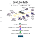
1
Text Part Number: 78-5776-01
Installing a Fan-Speed Controller
in Cisco 3620 Routers
Product Number: FAN-VSPD-3620=
This document describes how to install a fan-speed controller in Cisco 3620 routers.
The fan-speed controller kit consists of:
•
•
•
•
Fan-speed controller card mounted on a metal bracket
Package of screws
ESD-preventive wrist strap
This document
Use this document in conjunction with your router installation and configuration guide, the
Regulatory Compliance and Safety Information document for your router, and the Cisco IOS
configuration guides and command references.
Cisco documentation and additional literature are available in a CD-ROM package, which ships with
your product. The Documentation CD-ROM, a member of the Cisco Connection Family, is updated
monthly. Therefore, it might be more current than printed documentation. To order additional copies
of the Documentation CD-ROM, contact your local sales representative or call customer service.
The CD-ROM package is available as a single package or as an annual subscription. You can also
access Cisco documentation on the World Wide Web at http://www.cisco.com,
http://www-china.cisco.com, or http://www-europe.cisco.com.
If you are reading Cisco product documentation on the World Wide Web, you can submit comments
electronically. Click Feedback in the toolbar and select Documentation. After you complete the
form, click Submit to send it to Cisco. We appreciate your comments.
If you have questions or need help, see the “Cisco Connection Online” section on page 12.
Corporate Headquarters
Cisco Systems, Inc.
170 West Tasman Drive
San Jose, CA 95134-1706
USA
Copyright © 1998
Cisco Systems, Inc.
All rights reserved.
1
Safety Recommendations
This document contains the following sections:
•
•
•
•
•
•
•
Safety Recommendations, page 2
FCC Class B Compliance, page 5
Required Tools and Equipment, page 6
Removing the Cover, page 6
Installing the Fan-Speed Controller, page 8
Replacing the Cover, page 11
Cisco Connection Online, page 12
Safety Recommendations
Follow these guidelines to ensure general safety:
•
•
•
Keep the chassis area clear and dust-free during and after installation.
•
•
Wear safety glasses when working under any conditions that might be hazardous to your eyes.
Keep tools away from walk areas where you or others could fall over them.
Do not wear loose clothing that could get caught in the chassis. Fasten your tie or scarf and roll
up your sleeves.
Do not perform any action that creates a potential hazard to people or makes equipment unsafe.
Safety Warnings
Safety warnings appear throughout this publication in procedures that, if performed incorrectly, may
harm you. A warning symbol precedes each warning statement.
Warning Means danger. You are in a situation that could cause bodily injury. Before you work on any
equipment, be aware of the hazards involved with electrical circuitry and be familiar with standard practices
for preventing accidents. To see translations of the warnings that appear in this publication, refer to the
Regulatory Compliance and Safety Information document that accompanied this device.
Waarschuwing Dit waarschuwingssymbool betekent gevaar. U verkeert in een situatie die
lichamelijk letsel kan veroorzaken. Voordat u aan enige apparatuur gaat werken, dient u zich bewust
te zijn van de bij elektrische schakelingen betrokken risico's en dient u op de hoogte te zijn van
standaard maatregelen om ongelukken te voorkomen. Voor vertalingen van de waarschuwingen die
in deze publicatie verschijnen, kunt u het document Regulatory Compliance and Safety Information
(Informatie over naleving van veiligheids- en andere voorschriften) raadplegen dat bij dit toestel is
ingesloten.
Varoitus Tämä varoitusmerkki merkitsee vaaraa. Olet tilanteessa, joka voi johtaa ruumiinvammaan.
Ennen kuin työskentelet minkään laitteiston parissa, ota selvää sähkökytkentöihin liittyvistä
vaaroista ja tavanomaisista onnettomuuksien ehkäisykeinoista. Tässä julkaisussa esiintyvien
varoitusten käännökset löydät laitteen mukana olevasta Regulatory Compliance and Safety
Information -kirjasesta (määräysten noudattaminen ja tietoa turvallisuudesta).
Attention Ce symbole d'avertissement indique un danger. Vous vous trouvez dans une situation
pouvant causer des blessures ou des dommages corporels. Avant de travailler sur un équipement,
soyez conscient des dangers posés par les circuits électriques et familiarisez-vous avec les
2 Installing a Fan-Speed Controller in Cisco 3620 Routers
Safety Warnings
procédures couramment utilisées pour éviter les accidents. Pour prendre connaissance des
traductions d’avertissements figurant dans cette publication, consultez le document Regulatory
Compliance and Safety Information (Conformité aux règlements et consignes de sécurité) qui
accompagne cet appareil.
Warnung Dieses Warnsymbol bedeutet Gefahr. Sie befinden sich in einer Situation, die zu einer
Körperverletzung führen könnte. Bevor Sie mit der Arbeit an irgendeinem Gerät beginnen, seien Sie
sich der mit elektrischen Stromkreisen verbundenen Gefahren und der Standardpraktiken zur
Vermeidung von Unfällen bewußt. Übersetzungen der in dieser Veröffentlichung enthaltenen
Warnhinweise finden Sie im Dokument Regulatory Compliance and Safety Information
(Informationen zu behördlichen Vorschriften und Sicherheit), das zusammen mit diesem Gerät
geliefert wurde.
Avvertenza Questo simbolo di avvertenza indica un pericolo. La situazione potrebbe causare
infortuni alle persone. Prima di lavorare su qualsiasi apparecchiatura, occorre conoscere i pericoli
relativi ai circuiti elettrici ed essere al corrente delle pratiche standard per la prevenzione di incidenti.
La traduzione delle avvertenze riportate in questa pubblicazione si trova nel documento Regulatory
Compliance and Safety Information (Conformità alle norme e informazioni sulla sicurezza) che
accompagna questo dispositivo.
Advarsel Dette varselsymbolet betyr fare. Du befinner deg i en situasjon som kan føre til
personskade. Før du utfører arbeid på utstyr, må du vare oppmerksom på de faremomentene som
elektriske kretser innebærer, samt gjøre deg kjent med vanlig praksis når det gjelder å unngå ulykker.
Hvis du vil se oversettelser av de advarslene som finnes i denne publikasjonen, kan du se i
dokumentet Regulatory Compliance and Safety Information (Overholdelse av forskrifter og
sikkerhetsinformasjon) som ble levert med denne enheten.
Aviso Este símbolo de aviso indica perigo. Encontra-se numa situação que lhe poderá causar danos
físicos. Antes de começar a trabalhar com qualquer equipamento, familiarize-se com os perigos
relacionados com circuitos eléctricos, e com quaisquer práticas comuns que possam prevenir
possíveis acidentes. Para ver as traduções dos avisos que constam desta publicação, consulte o
documento Regulatory Compliance and Safety Information (Informação de Segurança e Disposições
Reguladoras) que acompanha este dispositivo.
¡Advertencia! Este símbolo de aviso significa peligro. Existe riesgo para su integridad física.
Antes de manipular cualquier equipo, considerar los riesgos que entraña la corriente eléctrica y
familiarizarse con los procedimientos estándar de prevención de accidentes. Para ver una traducción
de las advertencias que aparecen en esta publicación, consultar el documento titulado Regulatory
Compliance and Safety Information (Información sobre seguridad y conformidad con las
disposiciones reglamentarias) que se acompaña con este dispositivo.
Varning! Denna varningssymbol signalerar fara. Du befinner dig i en situation som kan leda till
personskada. Innan du utför arbete på någon utrustning måste du vara medveten om farorna med
elkretsar och känna till vanligt förfarande för att förebygga skador. Se förklaringar av de varningar
som förkommer i denna publikation i dokumentet Regulatory Compliance and Safety Information
(Efterrättelse av föreskrifter och säkerhetsinformation), vilket medföljer denna anordning.
Warning Read the installation instructions before you connect the system to its power source.
Warning Only trained and qualified personnel should be allowed to install or replace this equipment.
Warning Before working on a chassis or working near power supplies, unplug the power cord on AC units;
disconnect the power at the circuit breaker on DC units.
Installing a Fan-Speed Controller in Cisco 3620 Routers
3
Safety Recommendations
Warning Ultimate disposal of this product should be handled according to all national laws and regulations.
Safety with Electricity
Warning Before working on equipment that is connected to power lines, remove jewelry (including rings,
necklaces, and watches). Metal objects will heat up when connected to power and ground and can cause
serious burns or weld the metal object to the terminals.
Warning To avoid electric shock, do not connect safety extra-low voltage (SELV) circuits to
telephone-network voltage (TNV) circuits. LAN ports contain SELV circuits, and WAN ports contain TNV
circuits. Both LAN and WAN ports may use RJ-45 connectors. Use caution when connecting cables.
Warning Hazardous network voltages are present in WAN ports regardless of whether power to the router
is OFF or ON. To avoid electric shock, use caution when working near WAN ports. When detaching cables,
detach the end away from the router first.
Warning Before opening the chassis, disconnect the telephone-network cables to avoid contact with
telephone-network voltages.
Warning Do not work on the system or connect or disconnect cables during periods of lightning activity.
Warning Do not touch the power supply when the power cord is connected. For systems with a power
switch, line voltages are present within the power supply even when the power switch is OFF and the power
cord is connected. For systems without a power switch, line voltages are present within the power supply
when the power cord is connected.
Follow these guidelines when working on equipment powered by electricity:
•
Locate the emergency power-off switch in the room in which you are working. Then, if an
electrical accident occurs, you can quickly shut the power OFF.
•
•
Before working on the router, turn OFF the power and unplug the power cord.
Disconnect all power before doing the following:
— Installing or removing a router chassis
— Working near power supplies
•
•
•
Do not work alone if potentially hazardous conditions exist.
Never assume that power is disconnected from a circuit. Always check.
Look carefully for possible hazards in your work area, such as moist floors, ungrounded power
extension cables, and missing safety grounds.
4 Installing a Fan-Speed Controller in Cisco 3620 Routers
Preventing Electrostatic Discharge Damage
If an electrical accident occurs, proceed as follows:
•
•
•
Use caution; do not become a victim yourself.
•
Determine if the victim needs rescue breathing or external cardiac compressions; then take
appropriate action.
Turn OFF power to the router.
If possible, send another person to get medical aid. Otherwise, determine the condition of the
victim and then call for help.
Preventing Electrostatic Discharge Damage
Electrostatic discharge (ESD) can damage equipment and impair electrical circuitry. ESD can occur
when printed circuit cards are improperly handled and can result in complete or intermittent failures.
Always follow ESD prevention procedures when removing and replacing cards. Ensure that the
router chassis is electrically connected to earth ground. Wear an ESD-preventive wrist strap,
ensuring that it makes good skin contact. Connect the clip to an unpainted surface of the chassis
frame to safely channel unwanted ESD voltages to ground. To guard against ESD damage and
shocks, the wrist strap and cord must be used properly. If no wrist strap is available, ground yourself
by touching the metal part of the chassis.
Caution For safety, periodically check the resistance value of the antistatic strap, which should be between
1 and 10 megohms (Mohm).
FCC Class B Compliance
The equipment described in this document generates and may radiate radio-frequency energy. If it
is not installed in accordance with Cisco’s installation instructions, it may cause interference with
radio and television reception. This equipment has been tested and found to comply with the limits
for a Class B digital device in accordance with the specifications in part 15 of the FCC rules. These
specifications are designed to provide reasonable protection against such interference in a residential
installation. However, there is no guarantee that interference will not occur in a particular
installation.
You can determine whether your equipment is causing interference by turning it OFF. If the
interference stops, it was probably caused by the Cisco equipment or one of its peripheral devices.
If the equipment causes interference to radio or television reception, try to correct the interference
by using one or more of the following measures:
•
•
•
•
Turn the television or radio antenna until the interference stops.
Move the equipment to one side or the other of the television or radio.
Move the equipment farther away from the television or radio.
Plug the equipment into an outlet that is on a different circuit from the television or radio. (That
is, make certain the equipment and the television or radio are on circuits controlled by different
circuit breakers or fuses.)
Modifications to this product not authorized by Cisco Systems, Inc. could void the FCC approval
and negate your authority to operate the product.
Installing a Fan-Speed Controller in Cisco 3620 Routers
5
Required Tools and Equipment
Required Tools and Equipment
To install a fan-speed controller in a Cisco 3620 router, you need the following tools and equipment
(some of which are not included in the fan-speed controller kit):
•
•
•
Cisco 3620 router
ESD-preventive wrist strap
Number 2 Phillips screwdriver
Removing the Cover
This section describes how to remove the cover. You must remove the chassis cover to gain access
to the power supply and fan connectors.
Warning Do not touch the power supply when the power cord is connected. For systems with a power
switch, line voltages are present within the power supply even when the power switch is OFF and the power
cord is connected. For systems without a power switch, line voltages are present within the power supply
when the power cord is connected.
Take the following steps to remove the cover:
Step 1
Turn OFF power to the router and unplug the power cable.
Warning Before opening the chassis, disconnect the telephone-network cables to avoid contact with
telephone-network voltages.
Step 2
Remove all network interface cables from the rear panel.
Step 3
Position the router so the front panel is facing you. Remove the three screws located on
top of the cover near the front edge. (See Figure 1.) Set the screws aside in a safe place.
Step 4
Lift the front edge of the cover until the cover clears the front of the chassis.
(See Figure 1.)
6 Installing a Fan-Speed Controller in Cisco 3620 Routers
Removing the Cover
Figure 1
Lifting the Cover
Screw
SY
ST
EM
CO
H7242
RP
S
N
AU
X
AC
TIV 0 1
RE E
ADY
PC
MC
IA
1
0
Step 5
Pull the cover toward you until the metal tabs on the rear edge separate from the chassis
bottom. (See Figure 2.)
Step 6
Lift the cover free and set it aside.
When you are ready to replace the cover, see the “Replacing the Cover” section on page 11.
Figure 2
Removing the Cover
Screw
SY
ST
EM
H7241
RP
S
CO
N
AU
X
AC
TIV 0 1
RE E
ADY
PC
MC
IA
1
0
Installing a Fan-Speed Controller in Cisco 3620 Routers
7
Installing the Fan-Speed Controller
Installing the Fan-Speed Controller
This procedure describes how to install the fan-speed controller in the router:
Step 1
Figure 3
Unplug the fan connectors from the power supply connectors. (See Figure 3.)
Disconnecting the Fans from the Power Supply
Power supply
13299
Fan/power supply
connectors
Second fan not shown
Step 2
Remove the two screws, located near the power supply, from the motherboard. (See
Figure 4.) Save these screws for later reinstallation.
8 Installing a Fan-Speed Controller in Cisco 3620 Routers
Installing the Fan-Speed Controller
Figure 4
Removing Screws from the Motherboard
13300
Remove 2 screws
Step 3
Connect the two fan connectors to the two fan-speed controller connectors. (See
Figure 5.)
Note You can connect either fan connector to either fan-speed controller connector.
They are interchangeable.
Step 4
Connect any one of the two power supply connectors to the single fan-speed controller
power connector. (See Figure 5.)
Note Only one power supply connector is attached to the fan-speed controller. The
second power supply connector is not used, and does not affect system operation.
Installing a Fan-Speed Controller in Cisco 3620 Routers
9
Installing the Fan-Speed Controller
Figure 5
Attaching the Fan-Speed Controller Bracket to the Motherboard
Fan-speed
controller
bracket with
card on top
Power supply
connectors
13302
Fan
connectors
Step 5
Position the fan-speed controller bracket so that the card is on the top side, and the holes
in the bracket and motherboard are aligned. (See Figure 5.)
Step 6
Secure the bracket to the motherboard with the screws removed in Step 2. (See Figure 5.)
Note If you misplaced the previously removed screws, use the replacement screws
included with the fan-speed controller kit.
Note Avoid stressing the fan and power supply cables when the bracket is secured.
10 Installing a Fan-Speed Controller in Cisco 3620 Routers
Replacing the Cover
Replacing the Cover
This section describes how to replace the router cover:
Step 1
Position the router so the front panel is closest to you.
Step 2
Hold the cover so the tabs at the rear of the cover are aligned with the chassis bottom.
(See Figure 6.)
Figure 6
Replacing the Cover
Chassis cover
Chassis
tabs
Cover
tabs
Cover
tabs
SY
ST
EM
CO
H7243
RP
S
N
AU
X
AC
TIV 0 1
RE E
ADY
Front panel
Chassis bottom
PC
MC
IA
1
0
Step 3
Push the cover toward the rear, making sure that the cover tabs fit under the rear panel of
the chassis, and the chassis tabs fit under the top cover.
Step 4
Lower the front of the cover onto the chassis, making sure that the tabs on the side of the
cover fit inside the chassis side panels, and the tabs on the side of the chassis fit under the
cover side panels.
Step 5
Fasten the cover with the three screws you set aside in Step 3 of the “Removing the
Cover” section on page 6.
Step 6
Reinstall the chassis on a rack, desktop, or table. (See your router installation and
configuration guide for installation procedures.)
Step 7
Reinstall network interface cables.
If the router does not power on, see your router installation and configuration guide for troubleshooting
procedures.
Installing a Fan-Speed Controller in Cisco 3620 Routers
11
Cisco Connection Online
Cisco Connection Online
Cisco Connection Online (CCO) is Cisco Systems’ primary, real-time support channel. Maintenance
customers and partners can self-register on CCO to obtain additional information and services.
Available 24 hours a day, 7 days a week, CCO provides a wealth of standard and value-added
services to Cisco’s customers and business partners. CCO services include product information,
product documentation, software updates, release notes, technical tips, the Bug Navigator,
configuration notes, brochures, descriptions of service offerings, and download access to public and
authorized files.
CCO serves a wide variety of users through two interfaces that are updated and enhanced
simultaneously: a character-based version and a multimedia version that resides on the World Wide
Web (WWW). The character-based CCO supports Zmodem, Kermit, Xmodem, FTP, and Internet
e-mail, and it is excellent for quick access to information over lower bandwidths. The WWW version
of CCO provides richly formatted documents with photographs, figures, graphics, and video, as well
as hyperlinks to related information.
You can access CCO in the following ways:
•
•
•
•
•
WWW: http://www.cisco.com
WWW: http://www-europe.cisco.com
WWW: http://www-china.cisco.com
Telnet: cco.cisco.com
Modem: From North America, 408 526-8070; from Europe, 33 1 64 46 40 82. Use the
following terminal settings: VT100 emulation; databits: 8; parity: none; stop bits: 1; and
connection rates up to 28.8 kbps.
For a copy of CCO’s Frequently Asked Questions (FAQ), contact [email protected]. For
additional information, contact [email protected].
Note If you are a network administrator and need personal technical assistance with a Cisco
product that is under warranty or covered by a maintenance contract, contact Cisco’s Technical
Assistance Center (TAC) at 800 553-2447, 408 526-7209, or [email protected]. To obtain general
information about Cisco Systems, Cisco products, or upgrades, contact 800 553-6387,
408 526-7208, or [email protected].
This document is to be used in conjunction with your router installation and configuration guide, the Regulatory Compliance and Safety Information document for your router, and the Cisco
IOS configuration guides and command references.
AccessPath, Any to Any, AtmDirector, the CCIE logo, CD-PAC, Centri, the Cisco Capital logo, CiscoLink, the Cisco NetWorks logo, the Cisco Powered Network logo, the Cisco Press logo,
ClickStart, ControlStream, DAGAZ, Fast Step, FireRunner, IGX, JumpStart, Kernel Proxy, LoopRunner, MGX, Natural Network Viewer, NetRanger, NetSonar, Packet, PIX, Point and Click
Internetworking, Policy Builder, RouteStream, Secure Script, SMARTnet, SpeedRunner, Stratm, StreamView, The Cell, TrafficDirector, TransPath, VirtualStream, VlanDirector, Workgroup
Director, and Workgroup Stack are trademarks; Changing the Way We Work, Live, Play, and Learn and Empowering the Internet Generation are service marks; and BPX, Catalyst, Cisco,
Cisco IOS, the Cisco IOS logo, Cisco Systems, the Cisco Systems logo, Enterprise/Solver, EtherChannel, FastHub, FastPacket, ForeSight, FragmentFree, IPX, LightStream, MICA,
Phase/IP, StrataSphere, StrataView Plus, and SwitchProbe are registered trademarks of Cisco Systems, Inc. in the U.S. and certain other countries. All other trademarks mentioned in this
document are the property of their respective owners.
Copyright © 1998, Cisco Systems, Inc.
All rights reserved. Printed in USA.
9807R
12 Installing a Fan-Speed Controller in Cisco 3620 Routers