1
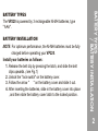
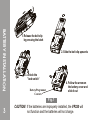
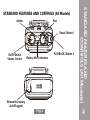
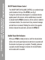
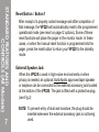
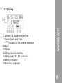
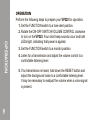
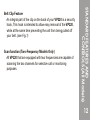
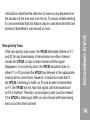
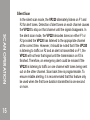
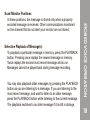
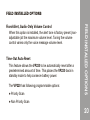
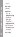
MODEL : VP220
USER MANUAL
TWO TONE VOICE PAGER
WITH DISPLAY
WARNING ..................................................................................................
BATTERY TYPES .....................................................................................
BATTERY INSTALLATION .......................................................................
STANDARD FEATURES AND CONTROLS (All Models) .....................
1
2
2
4
LCD Display ..................................................................................................8
VP200 CHARGER USER MANUAL .................................................. 23
WARNING .................................................................................................. 24
BATTERY CHARGER DESCRIPTION ................................................... 25
OPERATION GENERAL .......................................................................... 27
CHARGER INDICATOR LIGHTS ............................................................ 28
SPECIFICATIONS .................................................................................... 29
CONTENTS
OPERATION .............................................................................................. 9
SCAN OPERATION (TWO FREQUENCY ONLY) ................................. 12
STORED VOICE MODEL FEATURES AND CONTROLS .................... 15
STORED VOICE OPERATION ................................................................ 15
FIELD INSTALLED OPTIONS ................................................................. 19
BATTERY LIFE .......................................................................................... 20
ACCESSORIES ......................................................................................... 22
WARNING
WARNING :
X
1. Do not operate this product in a hazardous atmosphere.
X
WARNING
2. Do not replace or charge batteries in a hazardous atmosphere.
Contact sparking may occur while installing or removing batteries
and cause an explosion or fire.
X
3. Do not replace or change accessories in a hazardous atmosphere.
Contact sparking may occur while installing or removing accessories
and cause an explosion or fire.
X
4. Turn a radio off before removing or installing a battery or accessory.
X
5. Do not disassemble this unit in any way that exposed the internal
electrical circuits of the unit.
X
1
6. Do not substitute components. This could void the intrinsic safety
rating.
BATTERY INSTALLATION
X
NOTE: For optimum performance, the Ni-MH batteries must be fully
charged before operating your VP220.
Install your batteries as follows:
1. Release the belt clip by pressing the latch, and slide the belt
clips upwards. (see Fig.1)
2. Unlock the "lock switch" on the battery cover.
3. Follow the arrow "
" on the battery cover and slide it out.
4. After inserting the batteries, slide in the battery cover into place
, and then slide the battery cover latch to the locked position.
X
BATTERY TYPES
/ BATTERY INSTALLATION
BATTERY TYPES
The VP220 is powered by 3 rechargeable Ni-MH batteries, type
" AAA ".
X
2
BATTERY INSTALLATION
1. Release the belt clip
by pressing the latch
2. Slide the belt clip upwards
3. unlock the
"lock switch"
4. Follow the arrow on
the battery cover and
slide it out
Battery/Programmer
/
Contacts
Fig.1
3
CAUTION: If the batteries are improperly installed, the VP220 will
not function and the batteries will not charge.
Amber
Red
Reset / Button 1
On/Off Switch
Volume Control
PLAYBACK / Button 2
Battery Alert Indicators
External Accessory
Jack(Plugged)
Fig.2
STANDARD FEATURES AND
CONTROLS (All Models)
STANDARD FEATURES AND CONTROLS (All Models)
4
STANDARD FEATURES AND
CONTROLS (All Models)
5
ON/OFF Switch/Volume Control
The ON/OFF SWITCH/VOLUME CONTROL is a combined single
control located on the top of the VP220. (see Fig.2)
Turning the control knob a few degrees in a clockwise direction
applies power to the receiver, and an audible beep is sounded
to indicate that the VP220 is turned on. As the control is rotated in
a clockwise direction, the volume level of any received message
and alert tone is increased. Rotating the control in the opposite
direction reduces the audio level, and turns the VP220 off.
X
Audible/Visual Alert Indicators
When your VP220 is initially turned on, both the red and amber
LEDs on the control panel light and an alert tone is sounded until
the decoder circuit power-up is complete. Thereafter, whenever
a properly encoded message is received, the red LED flashes
and an audio alert is sounded.
X
X
Function Switch
According to the specific model ordered, the function switch will
be configured to 4 positions. Different function modes (monitor/
selective call, scan, etc.) can be configured for any position of
the switch.
X
X
Channel Monitoring
When the function switch is set to a monitor position, all voice
communications on the selected channel is heard through the
speaker. When monitoring channel 1 or 2 all ordered alert options
are functional.
X
STANDARD FEATURES AND
CONTROLS (All Models)
If the battery voltage falls below the level required for operation,
a low battery pulse tones sounds and the red LED flashes. If in
vibration mode, just the red LED flashes to indicate a low battery
state.
6
STANDARD FEATURES AND
CONTROLS (All Models)
7
Reset Button / Batton 1
After receipt of a properly coded message and after completion of
that message, the VP220 will automatically reset to the programmed
operational mode (see reset on pager 2 options). Some of these
reset functions will place the pager in the monitor mode. In these
cases, or when the manual reset function is programmed into the
pager, press the reset button to return your VP220 to the standby
mode.
X
External Speaker Jack
When the VP220 is used in high-noise environments or when
privacy is needed, an optional Gold Apollo approved lapel speaker
or earpiece can be connected to the external accessory jack located
at the bottom of the VP220. The jack is fitted with a protective plug.
(see Fig.2)
X
X
NOTE: To prevent entry of dust and moisture, the plug should be
inserted whenever the external accessory jack is not being
used.
LCD Display
LCD Display
1. 2 lines / 12 characters per line
* Current date and Time.
* “ “ indicator of the unread message.
2.Beep
3.Vibrate
4.Setting monitor function
5.Setting scan “F1,F2”Function.
6.Battery Indicator
7.Recording Indicator
8
OPERATION
Perform the following steps to prepare your VP220 for operation:
1. Set the FUNCTION switch to a tone-alert position.
2. Rotate the ON-OFF SWITCH/VOLUME CONTROL clockwise
to turn on the VP220. Four short beep sounds occur and both
LEDs light, indicating that power is applied.
X
X
X
OPERATION
9
X
3. Set the FUNCTION switch to a monitor position.
X
4. Listen for a transmission and adjust the volume control to a
comfortable listening level
5. If no transmission is heard, hold down the RESET button and
adjust the background noise to a comfortable listening level.
It may be necessary to readjust the volume when a voice signal
is present.
X
6. To push play button to play the unread message,display wil
show as below
6-1 Prompt source
6-2 Receiving time and date
6-3 Timer countdown
6-4 The number of reading message
7. Set the FUNCTION switch to the desired operating mode, i.e.,
selective call tone, selective call vibrate and monitor scan, etc.
8. Turn off the VP220 by rotating the ON-OFF SWITCH/VOLUME
CONTROL counterclockwise until a click is heard and the
mechanical stop is reached.
LCD DISPLAY
X
10
9.Basic Setting
*To Push button 1 and button 2 at the same time VP220 will
enter the setting mode.
*Push button 1 to enter for setting items; Push button 2 to
move the cursor
*In setting item mode, the button 1 is to change the number or
items, the button 2 is to move the cursor from left to right.
*In setting item mode, turn the function switch to go to stand
by mode without any setting modification.
BATTERY LIFE
Battery life depends upon the number of calls received and
length of each call, capacity and charge of the battery, and the
mode of operation.
A battery gauge, located between the knobs on top of the
pager can be used to determine remaining battery capacity. To
enable the battery gauge, press the reset button.
This will illuminate
the LED in the battery gauge. These green LED on the top of the
pager show remaining battery strength.
X
11
Scan function (Two-Frequency Models Only)
All VP220 that are equipped with two frequencies are capable of
scanning the two channels for selective call or monitoring
purposes.
X
STANDARD FEATURES AND
CONTROLS (All Models)
Belt Clip Feature
An integral part of the clip on the back of your VP220 is a security
hook, This hook is intended to allow easy removal of the VP220,
while at the same time preventing the unit from being pulled off
your belt. (see Fig.1)
X
12
SCAN OPERATION (TWO FREQUENCY ONLY)
Priority Scan
If the VP220 is programmed for priority scan, the frequency
programmed as frequency 1 (F1) is designated as the priority
channel. If there is no traffic on F1, the VP220 alternately listens
to F1 and F2 (Frequency 2) until a transmission is detected. If a
transmission is detected on F1, the VP220 stays on that channel
until the transmission ceases. The VP220 only decodes tones on
the F1 channel. No tones are decoded on the F2 channel.
X
SCAN OPERATION
13
If the VP220 detects a transmission on F2 it stops on F2 then
listens for transmissions on F1. Scan back time is programmable
and can be set to 0.5, 1, or 2-second increments. If a transmission
is detected on F1, the VP220 switches to F1 cutting off any
transmission on F2. When switching from F2 to F1, the VP220
listens for any tones and alerts if the proper tones are detected.
It should be noted that the detection of tones is very dependent on
the duration of the tone sent over the air. To ensure reliable alerting,
it is recommended that this feature only be used when the first tone
duration transmitted is one second or more.
X
SCAN OPERATION
Non-priority Scan
If the non-priority scan mode, the VP220 alternately listens on F1
and F2 for any transmission. A transmission on either channel
causes the VP220 to stop on that channel until the signal
disappears. In non-priority scan, the VP220 decodes tones on
either F1 or F2 provided the VP220 has listened to the appropriate
channel at the correct time. However, it should be noted that if
the VP220 is listening to traffic on F2 and an alert is transmitted
on F1, the VP220 will not hear that signal until the transmission
on F2 is finished. Therefore, an emergency alert could be missed
if the VP220 is listening to traffic on one channel with tones being
sent out on the other channel.
14
Silent Scan
In the silent scan mode, the VP220 alternately listens on F1 and
F2 for alert tones. Detection of alert tones on each channel causes
the VP220 to stop on that channel until the signal disappears. In
the silent scan mode, the VP220 decodes tones on either F1 or
F2 provided the VP220 has listened to the appropriate channel
at the correct time. However, it should be noted that if the VP220
is listening to traffic on F2 and an alert is transmitted on F1, the
VP220 will not hear that signal until the transmission on F2 is
finished. Therefore, an emergency alert could be missed if the
VP220 is listening to traffic on one channel with tones being sent
out on the other channel. Scan back time is programmable. To
ensure reliable alerting, it is recommended that this feature only
be used when the first tone duration transmitted is one second
or more.
X
SCAN OPERATION
15
Scan/Monitor Positions
In these positions, the message is stored only when a properly
encoded message is received. Other communications monitored
on the channel that do not alert your monitor are not stored.
X
X
You may also playback older messages by pressing the PLAYBACK
button as you are listening to a message. If you are listening to the
most recent message, and want to listen to an older message,
press the PLAYBACK button while listening to the current message.
The playback switches to an older message if it is still in storage.
STORED VOICE OPERATION
Selective Playback of Message(s)
To playback a particular message in memory, press the PLAYBACK
button. Pressing once replays the newest message in memory.
Twice replays the second most recent message and so on.
Messages cannot be played back during message recording.
16
Silent Scan
In the silent scan mode, the VP220 alternately listens on F1 and
F2 for alert tones. Detection of alert tones on each channel causes
the VP220 to stop on that channel until the signal disappears. In
the silent scan mode, the VP220 decodes tones on either F1 or
F2 provided the VP220 has listened to the appropriate channel
at the correct time. However, it should be noted that if the VP220
is listening to traffic on F2 and an alert is transmitted on F1, the
VP220 will not hear that signal until the transmission on F2 is
finished. Therefore, an emergency alert could be missed if the
VP220 is listening to traffic on one channel with tones being sent
out on the other channel. Scan back time is programmable. To
ensure reliable alerting, it is recommended that this feature only
be used when the first tone duration transmitted is one second
or more.
X
SCAN OPERATION
17
Scan/Monitor Positions
In these positions, the message is stored only when a properly
encoded message is received. Other communications monitored
on the channel that do not alert your monitor are not stored.
X
You may also playback older messages by pressing the PLAYBACK
button as you are listening to a message. If you are listening to the
most recent message, and want to listen to an older message,
press the PLAYBACK button while listening to the current message.
The playback switches to an older message if it is still in storage.
STORED VOICE OPERATION
Selective Playback of Message(s)
To playback a particular message in memory, press the PLAYBACK
button. Pressing once replays the newest message in memory.
Twice replays the second most recent message and so on.
Messages cannot be played back during message recording.
X
18
If there are no messages in memory, a "memory empty" one short
beep tone is heard while the PLAYBACK button is pressed.
STORED VOICE OPERATION
19
NOTE: A message is considered read if playback has been
initiated for the end of the message is reached,
whichever occurs first.
FIELD INSTALLED OPTIONS
Time-Out Auto Reset
This feature allows the VP220 to be automatically reset after a
predetermined amount of time. This places the VP220 back in
standby mode to help conserve battery power.
X
The VP220 has following programmable options:
X
● Priority Scan
FIELD INSTALLED OPTIONS
Fixed-Alert, Audio-Only Volume Control
When this option is installed, the alert tone is factory preset (nonadjustable) at the maximum volume level. Tuning the volume
control varies only the voice message volume level.
X
X
● Non Priority Scan
20
● Silent Scan
X
● Alert Duration
FIELD INSTALLED OPTIONS
X
● Priority Alert
X
X
X
X
X
X
X
● Reset Options
- Carrier reset
- Delayed N Carrier Reset
- Manual Reset
- Revert Reset
- Time Out Reset
- Delayed N Revert Reset
X
X
X
● Stored Voice Options
- Max Message Lengths
- Call Reminder
X
● Push-To-Listen
21
BATTERY LIFE
Battery life depends upon the number of calls received and length
of each call, capacity and charge of the battery, and the mode of
operation. A battery gauge, located between the knobs on top of the
pager can be used to determine remaining battery capacity. To
enable the battery gauge, press the reset button. This will illuminate
the LED in the battery gauge. These green LED on the top of the
pager show remaining battery strength.
X
X
● Desktop Battery Charger
● Desktop Battery Charger Amplifier with Antenna and Relay
● Earpieces
X
X
BATTERY LIFE / ACCESSORIES
ACCESSORIES
Gold Apollo offers these accessories below to increase
communications efficiently and provide many unique benefits.
22
VP200 CHARGER USER MANUAL
23
VP220 charger
User manual
IMPORTANT SAFETY INSTRUCTIONS – SAVE THESE INSTRUCTIONS
X
X
● This manual contains important safety and operating instructions.
● Before using the the charger, read all instructions and cautionary
markings on the (1) charger, (2) 3 rechargeable batteries, (3) pager.
X
WARNING :
X
X
WARNING
● When the pager or batteries are inserted, if the charger flashes
green light, it indicates the pager or the charger has Temperature
Thermistor Bad. Please re-insert the pager or batteries few times.
If the problem still occurs, please send the charger back for repair.
● Do not expose charger to rain or snow.
● To reduce risk of damage to electrical plug and cord, pull by the
plug when disconnecting the charger.
● Make sure the cord is located so that it will not be stepped on,
tripped over, or otherwise subjected to damage or stress.
● Do not operate charger with damaged power supply.
● Do not operate charger if it has received a sharp blow, been
dropped, or otherwise damaged.
● Do not disassemble charger.
● To reduce risk of electrical shock, unplug charger from outlet before
attempting cleaning.
X
X
X
X
X
24
BATTERY CHARGER DESCRIPTION
/ OPERATION GENERAL
25
BATTERY CHARGER DESCRIPTION
The single-unit charger is capable of charging batteries in the VP220
or three spare batteries. Dual colored LED indicators provide
information as to which batteries are being charged.
X
NOTE: It has to charge three batteries at the same time, not available
for individual battery.
OPERATION GENERAL
Charging Batteries While in the Receiver
1. Insert the transformer output plug into the recessed power
receptacle located on the rear of the charger (see below picture).
X
X
Power Jack
X
X
X
OPERATION GENERAL
X
2. Insert the transformer input plug into a 120volt, 60Hz receptacle.
3. Insert the VP220, with battery into the charger compartment
with the belt clip facing toward the back of the charger. Push
the VP220 all the way down until the belt clip latches and an
audible snap or click is heard.
4. When a pager is inserted in the charger, the PAGER indicator
lights on. When the charging process begins, during charging
process, the pager indicator light is solid red. When the charging
process is complete, the PAGER indicator light will change, in
color, from red to green.
5. To remove the VP220 alert monitor receiver, press the upper
end of the belt clip and lift the VP220 out.
6. To charge the three spare batteries, place the batteries into the
spare battery slot and push down until a snap or click is heard.
When the battery is inserted into the charger, the BATTERY
indicator lights on. When the charging process begins, during
charging process, the battery indicator light is solid red. When
the charging process is complete, the PAGER indicator light
will change, in color, from red to green. Removing the batteries
after charging (see the below picture).
26
NOTE:
When a pager and batteries are inserted in the charger at same
time, the pager pocket has priority. After the pager has completed
rapid charging, then the batteries will follow charging with red LED
solid red. Otherwise, the first item inserted, pager or batteries will
have priority in the charge cycle. For example, if batteries are in
place in the battery slot and then the pager is inserted into the
pager pocket, the batteries will be charged first. The BATTERY
indicator light will be solidly lit red and the PAGER indicator light
will be on. Once the batteries is fully charged, it then will start to
charge the pager.
X
OPERATION GENERAL
Battery Pack
Charging Pocket
BATTERY LED
27
PAGER LED
Charging Pocket
CHARGER INDICATOR LIGHTS
PAGER light solid orange
INDICATION SUMMARY
Charger is checking battery chemistry, or
Charger is waiting for BATTERY charger
cycle to complete
PAGER light solid red
PAGER is actively rapid charging
PAGER light green
PAGER rapid charge cycle completed and
in the maintenance mode
Charger is checking battery chemistry, or
BATTERY light solid orange Charger is waiting for PAGER charge cycle
to complete
BATTERY light solid red
BATTERIES are actively rapid charging
BATTERY light green
BATTERIES rapid charge cycle is completed
and in the maintenance mode.
CHARGER INDICATOR LIGHTS
LED STATUS
28
SPECIFICATIONS
SPECIFICATIONS
29
Parameter
Model VP220
Input Source
8.4 ~ 8.8 V DC 5 Watts ( 800 amp DC max.)
Weight:
6.17 oz. (175g)
Dimensions:
4.09 x 2.42 x 1.54
(104 x 61.5 x 39mm)
Rapid charging:
*Rapid charging method
A. Rapid charging method:
● Delta voltage
● TCO: 50˚C (typical)
● Timeout: 2.5 hours (typical)
B. Rapid charging current: 350 mA (typical)
X
Rapid charging time:
Approximately 2 Hours
Temperature Range:
0˚C to + 40˚C
NOTE
NOTE
762-00057-0
672- 00037- 0