1
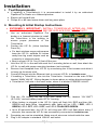
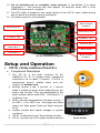
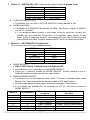
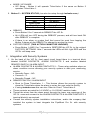
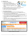
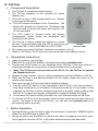
Installation and User’s Manual GF1082 V3.1.8 To sign up for ionleaks.com please visit www.ionleaks.com/signup www.PipeBurstPro.com 800-246-LEAK (5325) Congratulations on your new PipeBurst Pro Automatic Water Protection System! For the best user experience use ionleaks.com, this is the System’s online interface. Please visit www.PipeBurstPro.com for new component and troubleshooting information. Table of Contents INSTALLATION ..........................................................................................................3 I. II. TOOL REQUIREMENTS........................................................................................... 3 MOUNTING & INITIAL STARTUP INSTRUCTIONS .................................................... 3 SETUP AND OPERATION ........................................................................................4 VIP SR. (VALVE INTERFACE PANEL SR.)............................................................. 4 A. Component Description ................................................................................ 4 B. Operation Instructions ................................................................................... 5 C. Integration with Security Systems ............................................................... 7 II. IONLEAKS.COM ...................................................................................................... 8 A. Component Description ................................................................................ 8 B. Operational Instructions ................................................................................ 8 III. WIRELESS & WIRED SENSORS............................................................................. 9 A. Component Description ................................................................................ 9 B. Operational Instructions ................................................................................ 9 IV. FLOTRAX ............................................................................................................. 10 A. Component Description .............................................................................. 10 B. Operational Instructions .............................................................................. 10 C. Button Operation .......................................................................................... 10 D. FloTrax LED Definitions .............................................................................. 11 V. REPEATER ........................................................................................................... 11 A. Component Description .............................................................................. 11 B. Operational Instructions .............................................................................. 11 VI. FLOMETER .......................................................................................................... 12 A. Component Description .............................................................................. 12 B. Operational Instructions .............................................................................. 12 I. ANNUAL MAINTENANCE ....................................................................................... 13 2|Page Installation Tool Requirements I. If installing a TickerValve(s) it is recommended to install it by an authorized PipeBurst Pro Dealer or a licensed plumber. Electric drill and drill bits. Philips #1 or #2 hand screw driver and long nose pliers. II. Mounting & Initial Startup Instructions EXTREMELY IMPORTANT: INSTALL TICKERVALVE AFTER ALL FIRE SUPPRESSION LINES THAT MAY BE IN PLACE FOR THE FACILITY. 1. 2. 3. 4. 5. 6. Use an authorized PipeBurst Pro dealer or a licensed plumber to install the TickerValve in the building to ensure proper placement of the TickerValve. Position the VIP Sr. (Valve Interface Panel Sr.) For best wireless range performance keep the VIP Sr. antenna 24 inches away from big metal objects such as a security or electrical panel. TickerValve - Wiring Diagram Best to mount VIP Sr. five (5) feet off the floor. Hold the VIP Sr. to the wall and mark the 2 mounting holes on wall, then attach the VIP Sr. to wall with proper mounting hardware (not included). Remove front faceplate from VIP Sr. by unscrewing the 4 front screws and allow it to hang via the strain relief. Connect Ethernet into the Ethernet Jack to connect VIP Sr. to ionleaks.com. If installing a TickerValve, wire into the TickerValve 1 terminal on the main PCBA labeled “MAIN VALVE”. Wiring diagram is shown above or written directions below. TickerValve 2 will wire in the same order, where it is labeled “FREEZE VALVE”. Motor + Red Wire Motor Black Wire Open Blue Wire Closed Green Wire Sense White Wire 7. Plug the 12V battery into the 4 pin jack inside VIP Sr., labeled “12V BATT (S.L.A.B.)” and set battery inside VIP Sr. housing. When battery is plugged in the VIP Sr. lights will flash ALL RED and then ALL GREEN and beep twice. Immediately after lights will be: LED 1 RED, LED 2 GREEN, LED 3 OFF, LED 4 OFF, and LED 5 FLASH RED GREEN. Up to 90 seconds later, the VIP Sr. will chirp and LED 5 will flash about every 5 seconds, this means the VIP Sr. has successfully connected to ionleaks.com. 8. Faceplate can now be reinstalled. Make sure all wires are tucked inside the case. 9. Plug in AC adapter to standard 120VAC wall outlet. 3|Page 10. Go to ionleaks.com to complete setup process or tap Button 3 to setup TickerValve 1. This process may take approx. 30 seconds, when LED 3 turns GREEN the process is complete. 11. The FCC label is located on the inside surface of the VIP Sr. case, visible during the AC power and battery backup installation. 12. The basic system is now installed. Alarm Contact Output 2 Backup Battery Wired Sensor Jack AC Power Jack FloMeter 1 & 2 Ethernet Jack TickerValve 1 Alarm Input TickerValve 2 VIP Sr. Connections Diagram Alarm Contact Output 1 Setup and Operation I. VIP Sr. (Valve Interface Panel Sr.) A. Component Description 1. The VIP Sr. is the main controller for the PipeBurst Pro Sr. It includes basic operational instructions via its label, 5 buttons, 5 LED’s, a temperature sensor, audible alarm and can connect to ionleaks.com. 2. Buttons require a tap, 2 second, or 7 second holds to initiate the given action depending on the button and function. They are designated by the label numbers above each LED. 1 for Button 1, 2 for Button 2 etc. 3. LED’s, are also designated by the label number, 1 for LED 1, 2 for LED 2 etc., and lights are either green, red, flash green, flash red, flash red green or off. 4. Audible sounds also signal changes in system conditions. 5. VIP Sr. is defaulted to test TickerValves monthly. 6. VIP Sr. can store up to 63 unique wireless devices. 4|Page VIP Sr. Part #: VP200 B. Operation Instructions 1. Button 1 – SYNC DEVICES (can also be setup through ionleaks.com.) LED Color Green Red Flash Green Flash Red Flash Red Green Definition Devices Synced No Synced Devices Sync Mode Lost Sync Confirm Sync a. SYNC MODE: ENTER SYNC MODE: Press Button 1 for 2 seconds to enter SYNC MODE release when the VIP Sr. beeps 2 times. After the release LED 1 will begin to FLASH GREEN. The VIP Sr. is now ready to have wireless devices synced. To sync a device tap the red SYNC button on the underside of each device, i.e. Wireless Sensor, FloTrax, or Repeater. EXIT SYNC MODE: Tap Button 1 and the VIP Sr. will leave sync mode and return to normal operation OR if no device is synced within 5 minutes the VIP Sr. will timeout of sync mode. b. UNSYNC ALL DEVICES (THIS ACTION CANNOT BE UNDONE!) Press Button 1 for 7 seconds, all 5 VIP Sr. LEDs will turn RED and ALL of the synced wireless devices are cleared from the VIP Sr. memory. During the hold of Button 1 there will be short beeps at 2 seconds, ignore this, continue to hold until it beeps again at 7 seconds. To remove a single device from the system, while in Sync mode tap the Sync button on the device you wish to unsync. You can also use ionleaks.com to do this un-syncing. 2. Button 2 – FREEZE SENSOR (can also be setup through ionleaks.com.) LED Color Green Red Flash Green Flash Red Flash Red Green Definition On Off Freeze Detected a. TURN ON / OFF FREEZE SENSOR: Press Button 2 for 2 seconds to turn ON or OFF the FREEZE SENSOR. Factory default is ON. b. TURN ON / OFF ALARM CONTACT RELAY: Press Button 2 for 7 seconds to turn ON or OFF the ALARM CONTACT RELAY. During the hold of Button 2 there will be short beeps at 2 seconds, ignore this, continue to hold until it beeps again at 7 seconds. All LEDs will flash GREEN when ON or the LEDs will flash RED when OFF. Factory default is OFF. When ON it will trigger the ALARM CONTACT RELAY every time the system turns the water on or off. When OFF the ALARM CONTACT RELAY is only triggered on an alarm. 5|Page 3. Button 3 – WATER ON / OFF (can also be setup through ionleaks.com.) LED Color Green Red Flash Green Flash Red Flash Red Green Definition On Off Alarm Valve Fault a. TURN WATER ON / OFF: Tap Button 3 to turn ON or OFF the WATER. Factory default is ON. b. DURING ALARM: Tap Button 3 to SILENCE the audible ALARM. Tap Button 3 again to RESET the VIP Sr. ALARM. If a hardwired water sensor is wet when trying to reset the system the system will not open the TickerValve. If a wireless water sensor is wet when trying to reset the system, the system will open the TickerValve and then reclose the valve. System sensors MUST be dry to reset the system. 4. Button 4 – SECONDARY TICKERVALVE (Can also be setup through ionleaks.com.) LED Color OFF Green Red Flash Green Flash Red Flash Red Green Definition No TickerValve On Off Alarm Alarm Valve Fault a. MODE SELECT: ONLY USE THIS IF TICKERVALVE 2 IS INSTALLED. Press Button 4 for 2 seconds to enter MODE SELECT. There are 7 different modes for MODE SELECT. Factory default is set to Mode # Disabled as described in the chart below. b. DURING MODE SELECT: Tap Button 4 to move between each mode. To select a desired mode press Button 4 for 2 seconds while the desired mode’s LED light flashes. See the chart below to learn how each mode operates TickerValve 2. If no buttons are pressed for 15 seconds the VIP Sr. will timeout and exit MODE SELECT. Mode # LED Number 1 2 3 4 5 VIP Share Disabled 1 2 3 4 5 All - Red/ Grn All - Green TickerValve 1 Position Open / Closed Open / Closed Open / Closed Open / Closed Open / Closed Open / Closed Open / Closed 6|Page TickerValve 2 Position Open / Closed Closed / Open Closed / Open (Alarm Only) Open / Closed (Alarm Only) Closed / Open (Freeze Only) Independent TickerValve Does not exist c. MODE: VIP SHARE VIP Share - Button 4 will operate TickerValve 2 the same as Button 3 operates TickerValve 1. 5. Button 5 – SYSTEM STATUS (can also be setup through ionleaks.com.) LED Color Green Red Flash Green Flash Red Flash Red Green Definition System OK No Battery System Fault No AC Power a. REBOOT Press Button 5 for 7 seconds to REBOOT the VIP Sr. ALL LEDs will turn OFF during the REBOOT process, and will turn back ON after REBOOT is complete. If there is an alarm or system fault that cannot be reset from tapping the Button 3 please do the REBOOT to attempt to resolve the issue. b. FACTORY RESET (THIS ACTION CANNOT BE UNDONE!) Press Button 1 AND 5 for 7 seconds to RESTORE the VIP Sr. to the original FACTORY SETTINGS. After 7 seconds the LEDs will ALL light RED and the VIP Sr. will beep once. C. Integration with Security Systems 1. On the back of the VIP Sr. front panel circuit board there is a terminal block labeled ALARM CONTACTS, ALARM CONTACTS 2 and another labeled REMOTE SWITCH / ALARM INPUT. a. ALARM CONTACTS & ALARM CONTACTS 2 – These relay switches when an alarm condition occurs allowing your security system to alert your monitoring service. Normally Open – NO Common – C Normally Closed – NC b. REMOTE SWITCH / ALARM INPUT Short to Close TickerValve 1 – This feature allows the security system to close the TickerValve when the alarm is set as the user exits the facility. If using ionleaks.com this can also “Short to Close” TickerValve 2. c. These contacts are rated for 1A 24VDC or 1A 120VAC resistive loads. d. Thread the wires from the alarm panel through the lower rear openings of the VIP Sr. case and connect to the ALARM CONTACTS & ALARM CONTACTS 2 terminal block(s) as required. e. Consult the security system installation instructions, and/or the company that installed the system to best integrate the PipeBurst Pro Sr. with security systems. 7|Page II. ionleaks.com A. Component Description 1. Online interface for the PipeBurst Pro. 2. Allows for remote notifications anywhere in the world, including email, text, and phone calls. 3. Allows for setup and maintenance of your PipeBurst Pro from an easy to use online interface. 4. Records the PipeBurst Pro history and can be viewed in the Event Log. 5. Users can manage more than one system from one account. 6. Multiple users can manage the same system(s). 7. DHCP network required to use ionleaks.com. B. Operational Instructions 1. Go to ionleaks.com/signup to sign up for your ionleaks.com account. 2. Complete the Sign Up process and then log in to your ionleaks.com account. 3. Add your system(s) to your ionleaks.com account. a. You will need the Serial # of your VIP Sr. and this can be found on top of the unit in the lower right hand corner of the white sticker to the right of the barcode. 4. Once your System is confirmed, log back into ionleaks.com and your System will be now associated with your ionleaks.com user account. 5. Continue setting up your System via ionleaks.com by following the on screen instructions. 6. If any help is needed during the setup process or anytime, you can find more detailed information in the ionleaks.com user manual, which can be found on the Support tab when logged into ionleaks.com. Example of ionleaks.com User Interface 8|Page III. Wireless & Wired Sensors A. Component Description 1. The wireless water sensor can have an optional wired sensor plugged into the wireless sensor. 2. The wireless sensor operates on 2 AA batteries or AC adapter (not included). a. Do NOT place batteries in the wireless sensor if it is going to be powered with the AC adapter. Batteries are not for a backup. b. Be sure to place Positive (+) side of AA battery in first, to ensure proper Wireless & Wired Sensors functionality. Part #: FB200B & SK200B c. Replace AA batteries annually or replace batteries after the wireless sensor has alarmed due to water. 3. When the wireless sensor detects water via the gold plated sensor pins or the attached wired sensor the wireless sensor will produce an audible alarm and send a wireless signal to the VIP Sr. This will tell the VIP Sr. to close the TickerValve and the VIP Sr. will produce a visual and audible alarm. 4. The FCC Label is located inside the battery compartment, visible during the installation and removal of the batteries. 5. Wireless sensors will wake up 4 times a day to check proper communication to the VIP Sr. If this operation fails; the VIP Sr. will go into an alarm and LED 1 will FLASH RED for LOST SYNC. B. Operational Instructions 1. Apply desired power to the wireless sensor, either AC power or AA batteries. 2. Place VIP Sr. into SYNC MODE or add devices through ionleaks.com. 3. Tap the red SYNC button on the underside of the wireless sensor; it will then produce 3 beeps followed by a succession of beeps followed by 3 long beeps. Note: The wireless sensor must be synced to the VIP Sr. for the system to automatically turn off the water. 4. Repeat for each wireless sensor, when completed exit SYNC MODE on VIP Sr. 5. Place wireless sensors in the desired locations for the install. 6. Test each synced wireless sensor in the final installation location: a. Tap the red SYNC button on the underside of the wireless sensor; it will then produce 3 beeps followed by a succession of beeps followed by 3 long beeps. If this happens the wireless sensor is within wireless range and is properly communicating with the VIP Sr. If it does not happen a Repeater is needed to extend the signal. b. Or test each wireless sensor with water by wetting the sensor. 7. To remove a wireless sensor from the system, while in Sync mode tap the Sync button to unsync. Tap again to re-sync the wireless sensor. You can also use ionleaks.com to do this syncing and un-syncing. 9|Page IV. FloTrax A. Component Description 1. The FloTrax is a wireless remote control. 2. The FloTrax operates on the included AC power adapter only. 3. The FloTrax has 1 LED located above the 1 Button on the front of the device. a. The LED shows the status of the TickerValve. The Button will operate the TickerValve. The Button can also be used to silence the alarm and rest the VIP Sr. from an alarm. 4. The FCC Label is located inside the battery compartment, visible during the installation and mounting of the device. 5. The FloTrax is always awake and checks in 4 times FloTrax per day. If this operation fails; the VIP Sr. will go into an Part #: FT200 alarm and LED 1 will FLASH RED for LOST SYNC. 6. The maximum number FloTrax’s allowed in a system is two (2). 7. When in VIP Share, the FloTrax can only be synced to one share at a time. B. Operational Instructions 1. Apply AC power to the FloTrax. 2. Place VIP Sr. into SYNC MODE or add devices through ionleaks.com. 3. Tap the red SYNC button on the underside of the FloTrax; it will then produce 1 long beep followed by a succession of beeps followed by 3 long beeps. Note: The FloTrax must be synced to the VIP Sr. for the FloTrax to operate the PipeBurst Pro Sr. 4. Repeat for each FloTrax, (Up to 2) when completed exit SYNC MODE on VIP Sr. 5. Place the FloTrax in the desired location for the install; make sure there is AC power in this location. 6. Test each synced FloTrax in the final installation location: a. Tap the red SYNC button on the underside of the FloTrax; it will then produce 1 long beep followed by a succession of beeps followed by 3 long beeps. If this happens the FloTrax is within wireless range and is properly communicating with the VIP Sr. If it does not happen a Repeater is needed to extend the signal. b. Or test each FloTrax by turning the water on or off with the button on the front. 7. To remove a FloTrax from the system, while in Sync mode tap the Sync button to unsync. Tap again to re-sync the FloTrax. You can also use ionleaks.com to do this syncing and un-syncing. C. Button Operation 1. Tap the Button on the FloTrax to open and close the TickerValve. GREEN light is Water On and RED light is Water Off. 2. During an alarm use the Button to silence the alarm by tapping the button once. Tap it again to reset the VIP Sr. if the water sensors are dry and leak fixed. 10 | P a g e D. FloTrax LED Definitions LED Color Green Red Flash Red Flash Orange Flash Red Green Definition Water On Water Off Alarm System Fault Valve Status Unknown V. Repeater A. Component Description 1. The Repeater is a wireless range extender. 2. The Repeater operates on the included AC power adapter only. 3. The FCC Label is located on the bottom side of the device. 4. The maximum number of synced Repeaters allowed in a system is two (2). Repeater Part #: RP100B B. Operational Instructions 1. Apply AC power to the Repeater. 2. The Repeater does not have to be synced. Unless you want to double check it is in range by tapping the sync button on the device. OPTIONAL STEPS (3 to 7) 3. Place VIP Sr. into SYNC MODE or add devices through ionleaks.com. 4. Tap the red SYNC button on the underside of the Repeater; it will then produce 1 long beep followed by a succession of beeps. 5. Repeat for each Repeater, (Up to 2) when completed exit SYNC MODE. 6. Place the Repeater in the desired location for the install; make sure there is AC power in this location. 7. Test each synced Repeater in the final installation location: a. Tap the red SYNC button on the underside of the Repeater; it will then produce 1 long beep followed by a succession of beeps. If this happens the Repeater is within wireless range and is properly communicating with the VIP Sr. If it does not happen move the Repeater closer to the VIP Sr. 8. To remove a Repeater from the system, while in Sync mode tap the Sync button to unsync. Tap again to re-sync the Repeater. You can also use ionleaks.com to do this syncing and un-syncing. a. UNLESS the Repeater was not synced in the first place. 11 | P a g e VI. FloMeter A. Component Description Must have ionleaks.com to use the FloMeter. 1. ionleaks.com is the user interface for the FloMeter. 2. The FloMeter will measure the flow of water. 3. The FloMeter works with the TickerValve(s) to turn OFF, LOW FLOW or only send notifications when an alarm criterion is met. 4. Different sizes of FloMeters are available, up to 2”. 5. The FloMeter may make a slight operational sound when water is flowing; this slight operational sound is considered normal and should be expected. 6. Different FloMeters measure to different accuracies, they range from 1 gallon to 100 gallons per pulse. FloMeter 7. Can be used to detect “hidden” leaks that water sensors Part #: Varies w/ Size cannot detect. 8. The maximum number of FloMeters per VIP Sr. is two (2). B. Operational Instructions 1. Connect the FloMeter’s GREEN wire from the FloMeter’s digital encoder to COM and the FloMeter’s BLACK wire to FM1 on the back of the VIP Sr. faceplate. a. The FloMeter’s RED wire will not be used. 2. FloMeter 1 & 2 will share the middle terminal, COM. 3. The remaining steps of the setup process for the FloMeter are done through ionleaks.com. 4. Repeat for FloMeter 2, if installed, except connect to FM2 & COM. 5. For instructions on completing the setup, consult the ionleaks.com user manual. 6. To learn more about the FloMeter please visit www.PipeBurstPro.com/support. 7. Note: You must have your VIP Sr. connected to the internet and ionleaks.com to use the FloMeter and if it is not, the FloMeter will NOT trigger the TickerValve. 12 | P a g e Annual Maintenance I. A. B. Cleaning Annual system cleaning is recommended to ensure proper operation. Cleaning the wireless & wired sensors with a wet towel accomplishes many tasks at once. The cleaning keeps the gold sense pads free of any dirt, debris, or other material that may inhibit the detection of water. II. Testing A. B. Annual system testing is recommended to ensure proper operation. Test the wireless devices by tapping the SYNC button on the bottom side of the device. Replace batteries in all wireless sensors after one year of use. III. Annual Maintenance Agreement A. The local PipeBurst Pro Dealer may offer an Annual Maintenance Agreement to annually perform the above tasks and more. Check with your local PipeBurst Pro Dealer for details. 13 | P a g e Customer Support: GreenField Direct, LLC 14015 238th Street Greenwood, NE 68366 http://www.pipeburstpro.com/contact/ Phone: 800-246-LEAK (5325) Fax: (402) 944-2907 E-Mail: [email protected] Operating Hours: Monday - Friday, 7:00am - 6:00pm CST (Excludes Major Holidays) Warranty - PipeBurst Pro Products 7 Year Limited Warranty th GreenField Direct, LLC of 14015 238 St, Greenwood, NE 68366 (“Warrantor”), warrants to the original purchaser and installed location of the PipeBurst Pro, manufactured by Warrantor, and to any person to whom such originally installed equipment is transferred to via the transfer of said real property that original installation was made, that such equipment shall be free from defects in materials and workmanship during a two (2) year period; additionally the electric valve actuator enclosure and its’ electronic components inside, shall be free from interior moisture damage for a period of seven (7) years; both periods commencing upon the receipt of order date for such equipment from the original purchaser thereof; (the “warranty periods”). Product should be registered to be covered by warranty. Note: Please register the PipeBurst Pro to activate your warranty http://www.pipeburstpro.com/support/warranty-registration/ FCC Compliance Statement: This device complies with part 15 of the FCC Rules. Operation is subject to the following two conditions: (1) This device may not cause harmful interference, and (2) this device must accept any interference received, including interference that may cause undesired operation. Changes or modifications not expressly approved by the party responsible for compliance could void the user's authority to operate the equipment. Power Requirements: For Indoor Use Only (Except TickerValve) Requirements for US & Canada Use supplied AC Adapter or AC Adapters purchased from PipeBurst Pro Dealer Do NOT use AA batteries in wireless sensor while using AC power VIP Sr. Input Output 100-240V ~50/60Hz 1.0A MAX 18V DC 2.22A Wireless Sensor / FloTrax / Repeater Input Output 100-240V ~50/60Hz 0.2A MAX 5V DC 1.2A 14 | P a g e Notes: 15 | P a g e To sign up for ionleaks.com please visit www.ionleaks.com/signup www.PipeBurstPro.com 800-246-LEAK (5325) 16 | P a g e


![20120815_PipeBurst Pro Jr User Manual V1[...]](http://vs1.manualzilla.com/store/data/005915031_1-fc76e6520fc4c8a26c3a91dcf3e505a9-150x150.png)