1
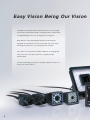
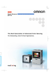
N E W
Vision sensor
with built-in LCD monitor
"Smart Sensor" ZFX-C
"Essential Innovation
for Future Generations"
Easy Vision Being Our Vision
The Omron's new ZFX-C Smart Vision Sensor is a total Image
Processing system that includes everything from a camera with
an integrated light source to an image-processing unit.
With Omron's newly developed proprietary measurement
algorithm, the parameter can be set through only a few steps
involving the operation of a touch-panel color monitor.
This “Smart” user interface provides simplicity of usage giving
anyone all they can need to perform a complete image
enhancement.
The new technology and style of the ZFX-C paves the way to a
new era of vision sensors.
2
“Smar t Recipe”
with condensed know-how
World's first
Capturing the image processing know-how Omron has accumulated over many years, the world's first
“Smart Recipe” has radically reduced setting up time allowing for greater productivity.
One-touch automatic setting
The essential skills for image processing are now packaged into Omron's unique algorithm. The setting
that traditionally required much fumbling is now made easy with the “select from auto listed options”
using recipes. Lighting setup, the longtime problem for image processing, and the tricky parameter
details involved in measurement setup, can now be done automatically with just the flip of a switch.
3
Smart
Recipe
Smart Recipe is on Omron's invention of 3-step setting procedure.
By adopting a new algorithm to encapsulate “human know-how”, the auto setup
for lighting and measurement now possible.
Anyone can rapidly perform a high level of image processing.
Step1
Choose best lighting
Patent pending
The know-how and trial and error that have been indispensable and required much time
and effort up to now in lighting setup is now an automated process. By just selecting the
best one from the candidate images automatically captured by changing the lighting
pattern with the auto-lighting, anyone can easily find the optimal lighting. User can now
easily determine settings for shiny work with high degrees of reflection and black
monochrome work with low degrees of reflection, something very tricky before. In
addition, when a more detailed setup is needed, the customized setup can be used to
incorporate know-how.
Automatic lighting setup
With automatic lighting setup, user can simply select
the best image from thumbnail of candidate images.
Customized lighting setup
A more detailed set up is possible with the customized
lighting setup while looking at the image.
Built-in lighting camera that enables an advanced automatic lighting
The Built-in lighting camera and improved controller brings
about an even higher degree of automatic lighting. With this
camera you can produce up to a maximum of 1296 patterns of
reflective lighting making the chore of choosing lighting
equipment unnecessary. The lighting setup can be managed as
digital data so it is possible to store the optimal setup for each
job, and it smoothly handles the changing of settings. It is also
possible to fine-tune the customized setup can be added.
4
Smart sensor
ZFX- C
Step2
Choose measurement icon
Step3
Draw region, press and go
The measurement method can be specified by just choosing
Just specify the region of interest and press Auto key and
the icon from out of a total of 9 measurement items for
the system will determine the most suitable parameters for
different types of inspection.
the target image.
Now anyone can easily perform a complex and advanced
parameter setting which used to require special knowledge
Pattern
Sensiti
Defect
Area
Hue
Bright
and cumbersome steps.
Customized setting is also possible by fine tuning the
parameters automatically set up. The time required to set up
parameters can be significantly reduced.
Position
Width
Width measurement
Count
Basic operations merely through
selection of on-screen icons
Intuitive operations
Indicate the region
Press the Auto key
Obtain the width
Appropriate filters and edge scan directions
for width measurement can be automatically
set by analyzing the target image.
Easily adjusts position
3-step position correction
Even when the position of work changes due to the
Step 1
2 model
1 model
Area
Position
Step 2
Step 3
Indicate each region
(red frame) of the
position correction.
Press Auto key.
conveyer condition, the excellent position correction
function can come into play allowing adjustment using
the work contours, two stage position correction and so
on. With the auto setup, position difference can be easily
Select the suitable position
correction icon for
different tests
adjusted to enable stable measurement.
In response to the position
difference,
the measurement region is
automatically adjusted.
No position correction
Position corrected
5
Tailored Measurement item
Including two shape measurement items, the system contains 5 categories and 9 types of
Shape, Size, Edge, Bright and Hue, Application measurement items.
It responds to the variety of inspection requirements in the manufacturing sites.
Shape measurement item
Pattern search
Fastest in the industry
The shape measurement is a fundamental algorithm for image processing. By adopting a new
image processor, the pattern search achieves a balance in the three factors of speed,
precision and stabilization, something that
was an arduous task until now. It now
supports a 360-degree revolving search and
a sub-pixel processing of 1000 to 1 pixel
units as well as a multi area searcher. The
robust pattern search can respond to the
A further improvement is the balance achieved in revolving
searches that occur in pattern matching for a revolving work.
The most time-consuming 360-degree revolving search can
be performed with an excellent accuracy.
multitude of inspects and measurements of
any application.
Sensitive search
NEW
When it comes to the difficult processing of detecting small differences, the Omron's
unique sensitive search matches
good
work at a smallest detail and in doing
defective
so makes such detection all the more
possible.It resists variations in
position and density to capture even
the smallest detail in the complex
patterns.
OK
NG
It is possible to detect even the smallest differences in the work.
Application specific measurement item
Defect
6
Size measurement item
Region
It is used to detect smears, scratches,
Detects the existence of work within a
chipping and burrs on the work. Defects
region and measures its size based on
are displayed on the screen, which makes
the area to perform various
it ideal tool for visual inspection.
classification.
Almost indistinguishable
scratches can be detected
after enhancing contrast
using the color filter.
LED illumination is determined based on the area
of extracted color.
Counts the number of
scratches
Smart sensor
ZFX- C
Bright and Hue measurement item
Edge measurement item
Hue
NEW
Position
The three factors in color, i.e. hue, saturation and brightness
The existence or not and the position
value, are measured and digitalized. And whilst an accurate
of the edge is measured. Oblique
differentiation of the color is performed, it is also possible to
edges can now be measured even in
measure the color variety with the deviation measurement
complex conditions and even more
function (with color camera connected).
accurate position measurements can be taken. The peak
Normal time
When lowering illumination
bottom measurement function that can accurately capture
the edges is now supported.
Width
The individual threshold for the hue, saturation and brightness value parameters
can be set up so that even if one of them is different, it can be detected accurately
and intensely. On the other hand, by expanding the range for the brightness value
and saturation, and so on, it is possible to stabilize the color detection in the hue
without any interference from illumination alterations.
The width of the edge is measured.
maximum
minimum
By using the edge partitioning
method, it is possible to measure the
maximum and minimum width.
Bright
Count
Measures the brightness
within a region. It can be
The number of edges inside the area
used for checking the
is counted. Based on the number of
presense of a component,
etc., by generating
average density and
edges on the pre-registered good
Based on the change in brightness, the
presense of a screw (OK or NG) is determined.
model, it counts the edges in the
area and determines the correctness.
density deviation values.
Functions to support optimal measurements
Up to 32 regions
In one captured image, it is possible to
measure a multiple up to 32 regions.
When carrying out difficult inspection, it is
possible to set-up a color filter and color
extraction for each measurement item.
Smear
check
Cap
detection
by color
abstraction
Labeling
error
check
Gray filtering setup
using double screen
For each measurement item, it is possible to
run 8 types of gray filtering such as
expansion and contraction to enable stable
measurements. Through the “setup while
looking” option that makes it possible to
check the preview, the optimal gray filtering
can be selected.
Measures three regions.
Screen registration function
Calculations function
It is possible to register the image used in the setup. When you use the live
image during setup sometimes the set up is not correct due to position
differences in the work. However, with the registered image saved in the SD
memory card as a“master image for setup”, it can be easily verified when
abnormal measurements occur.
It is possible to make arithmetical calculations for measurement values, and
calculations involving general functions, trigonometry, geometrical functions and
logical functions. It is possible to setup internal variables, and complex calculations
can be carried out.
7
Visualized Controller
Smallest in class controller build in embedded LCD saves space and time.
Visualized setting and monitoring
Smallest in class
Despite its small form factor, the enlarged screen significantly improves the visibility and
the ease of operation. The method of operation can be selected from 3way - the touch
pen, key pad or console.
Enlarged screen enables
wide range of views
130mm
90mm
Simple setting with
large screen
Touch pen
key pad
Console
Overview with
thumbnail screen
Rich interface support
Automatically detects the connected camera and displays the appropriate menu. With rich selection of
interface including parallel RS-232C/RS-422, USB 2.0, the extensibility is superior.
Camera
Camera I/F
RGB monitor
USB2.0
FULL SPEED
PLC
RS232-C/RS422
Console
SD memory card
Parallel I/O terminal
Ethernet
8
VGA (640 × 480)
Smart sensor
ZFX- C
Intensive camera solutions
8 types of cameras that can be selected for different types of work to achieve optimal measurement.
Built-in lighting camera
C-mount camera unit
NEW
Triple-speed camera (IP65)
Triple-speed camera
Line up of 6 types of built-in lighting cameras that do not
This product line includes C-mount camera that can select
need lighting selection or setup. The color camera can
the lens to match the field. It can be used in combination
respond to a wide range of work with a 5-150mm field of
with optional lighting such as transmitted lighting, low angle
view. Through image compression and partial capturing, it
lighting and bar lighting, etc. to support different inspection
can support a high-speed line.
types.
ZFX-SC
ZFX-S
(color)
(monochrome)
ZFX-SC50 (color)
ZFX-SR10 (monochrome)
Field of view 5
9 mm
Field of view 10
50 mm
(IP67 model available)
ZFX-SC90 (color)
ZFX-SR50 (monochrome)
Field of view 10
50 mm
Field of view 50
Innovative triple-speed camera
Performs fast transfer of 11.1ms that are 3 times faster than standard
cameras and 1.5 times faster than high-speed cameras while
maintaining a resolution of the whole screen. In addition, a super
speed, minimum 3.2ms transfer is possible with image compressions
and partial capturing.
90 mm
(IP67 model available)
Standard
camera
33.3ms
Double-speed
camera
16.7ms
Triple-speed
camera
ZFX-SC150 (color)
Field of view 80
ZFX-SC10 (color)
Field of view 5
9 mm
Fastest in the industry
150 mm
(IP67 model available)
Triple-speed
camera,
with compression
capturing
11.1ms
3.2ms
Excellent ease of use
Flexible installation
Hybrid interface
Flexible installation supported for
different mounting site conditions. It
can be mounted on DIN rail as well as
on the control panel surface. (Optional
panel mount adapter available.)
A new interface that supports both
parallel I/O and terminal platform to
dramatically improve the ease of
wiring.
9
advanced
Color Engine
The ZFX-C's advanced auto-color processing ability makes stable and accurate
measurements a reality, even for usually difficult to detect contrast and low lighting work.
Automatic color filter
Industry's first
Even for images clearly distinguishable in color, when
Red
converted to monochrome the contrast tends to
(auto)
become low. Color filter analyzer automatically selects
Magenta
Yellow
(auto)
(auto)
the optimal color filter (auto color filter) based on the
image analysis result to adjust the contrast, to allow
for stable image measurement. Any intermediate color
Gray
can be arranged for the color filter using custom
(auto)
settings.
Blue
Green
(auto)
(auto)
(color)
Cyan
Filter can be customized
for intermediate colors
(auto)
Without filter
(monochrome)
With filter
(monochrome)
Choose desired color
NEW
Simply select from the list of colors
It is now possible to run an automatic pickup of color, something that used to be a
complex procedure, using
simply the Auto key. The
advanced color engine
automatically detects the color
distribution in the selected
range and automatically lists
up to 4 optional color pickup in
Select color
to be pickup
the order of color area. After
that, user can simply select the
desired color to be pickup.
Specify the pickup area and press the Auto key
to display 4 optional colors for pickup.
pickup image
Fine-tuning by using dual-screen
The auto color pickup can fine-tune each of the hue, saturation
and brightness value. Using double screens, the source image and
the color pickup image can be compared and adjusted. This
enables easy and stable pickup of colors with low illumination
(traditionally difficult to pickup) and colors with large variation. The
efficiency of operation is greatly increased.
Source image
10
Smart sensor
ZFX- C
Versatile support tool
The concept behind Smart Recipe that eradicates the pain of image processing has been
leveraged in the system ramp-up and deployment.
Image storing and re-measurement
Stores up to 100 files of image data in the main
memory without slowing measurement speed.
Images data can be re-measured so even with
a high-speed line, for example, the results of
NG images can be
grouped and stored
separately.
the measurements can be checked at leisure
afterwards.
On-site fine adjustment
NEW
On site variety adjustment of work is essential. Without
returning to the menu mode, the measurement region, color
contrast setup and so on can be tuned in adjust mode,
using double screen to compare with the original image.
The measurement results of the stored images can also be
displayed so the unnecessary rejects can be efficiently
reduced.
Variety adjustment can be
controlled Simply using
the adjust mode.
Visualized monitoring and analysis
NEW
Through a list/individual view of measurement results, and a logging monitor display,
user can easily understand the measurement situation. The results display can be
chosen from 9 patterns including
individual results view (upper left,
upper middle), lists of results/region
view (lower left, lower middle), list of
results/All results view (upper right),
and data list view (bottom right). The
results can be reviewed in detail which
is useful for statistical analysis.
Password function
Display capture function
It is possible to set up a password that alters
between operating mode and other. This protects
against operational errors at the manufacturing site.
Display images can be captured and stored in
the SD memory card. Useful for report
documentation.
11
Ordering Information
Controllers
Power supply
Appearance
Circuit type
Model
NPN
ZFX-C10
PNP
ZFX-C15
DC21.6 to 26.4V
Cameras
Type
Appearance
Setting distance
Sensing area
Model
34mm to 49mm
4.9mm x 4.9mm
to 8.9mm x 8.9mm(variable)
ZFX-SR10
ZFX-SR10R (See note.)
38mm to 194mm
9.8mm x 9.8mm
to 49mm x 49mm(variable)
ZFX-SR50
ZFX-SR50R (See note.)
34mm to 49mm
4.9mm x 4.9mm
to 8.9mm x 8.9mm(variable)
ZFX-SC10
ZFX-SC10R (See note.)
31mm to 187mm
9.8mm x 9.8mm
to 49mm x 49mm(variable)
ZFX-SC50
ZFX-SC50W(IP67)
ZFX-SC50R (See note.)
67mm to 142mm
49mm x 49mm
to 89mm x 89mm(variable)
ZFX-SC90
ZFX-SC90W(IP67)
ZFX-SC90R (See note.)
115mm to 227mm
89mm x 89mm
to 148mm x 148mm(variable)
ZFX-SC150
ZFX-SC150W(IP67)
ZFX-SC150R (See note.)
Remarks
Monochrome type
Camera with lighting
Color type
(ZFX-SC50)
Monochrome type
Camera only
Color type
The CCTV lens is selected according to the range of
detection and the installation distance.
Cable length:2m
ZFX-S
ZFX-SC
Note. Equipped with a robot cable.
Cables
Accessories
Type
Cable length
Camera Cable Normal type
(See note 1.)
Robot cable type
Normal type
(bending direction: A, See note 3.)
Right-angle
cable type
Camera Cable Robot
(bending direction: A, See note 3.)
Normal type
(bending direction: B, See note 3.)
Robot cable type
(bending direction: B, See note 3.)
Camera
Extension
Cable
Model
Console
ZFX-KP (2m / 5m)
3m
ZFX-VSR
LCD Monitor
FZ-M08
3m,8m
ZFX-VSLA 3M/8M
ZFX-VSRLA 3M
3m
3m,8m
ZFX-VSLB 3M/8M
3m
ZFX-VSRLB 3M
3m
ZFX-XC3A (See note 2.)
8m
ZFX-XC8A (See note 2.)
3m
ZFX-XC3AR (See note 2.)
Parallel I/O Cable
2m,5m
ZFX-VP
RS-232C Cable
2m
ZFX-XPT2A
RS-422 Cable
2m
ZFX-XPT2B
Monitor Cable
2m,5m
FZ-VM
Special USB cable
1.8 m
ZFX-XUSB
Note 1: It is necessary for ZFX-S and ZFX-SC. ZFX-SR_/SC_ is a cable drawing out type,
it doesn't use it.
Note 2: Up to two camera extension cables can be connected to the camera cable as
long as the total cable length between the controller and the camera does not
exceed 19 m.
Note 3: Cable Bending Directions
12
Model
ZFX-VS
Normal type
Robot cable type
Type
3m,8m
Bending Direction A
(Model numbers ending in "A")
Bending Direction B
(Model numbers ending in "B")
The Cable bends
downward at the
Camera.
The Cable bends
upward at the
Camera.
The Cable bends
toward the front panel
at the Controller.
The Cable bends
toward the back panel
at the Controller.
Panel Mount Adapters
ZFX-XPM
bar lighting
ZFV-LTL01
Optional Lighting
bar double-lighting
ZFV-LTL02
(See note 1.)
bar low-angle lighting
ZFV-LTL04
light source for
through beam
ZFV-LTF01
CCTV Lenses /Extension Tubes
3Z4S-LE series
External Lighting
3Z4S-LT series
Strobe Controller (See note 2.)
Manufactured by MORITEX Corporation
3Z4S-LT MLEK-C100E1TSX
Note 1: It is possible to ZFX-SC50 and ZFX-SC90 use it.
Note 2: It is possible to ZFX-S and ZFX-SC use it. It uses it so that the controller may
control an external lighting. The Strobe Controller cannot be connected when
using a Right-angle Camera Cable.
Specifications
Controllers
ZFX-C10
Item
Number of connected cameras
1
Connectable camera
ZFX-SR_/SC_/S/SC
Processing resolution
When ZFX-SR_/SC_ is connected:464 (H) x464 (V)
When ZFX-S/SC is connected:608 (H) x464 (V)
LCD monitor
Display
Indicator
ZFX-C15
3.5" TFT color LCD (320 x 240 pixels)
"Measuring" indicator (color: green): RUN
Trigger indicator (color: blue): ENABLE
Judgment indicator (color: orange): OUTPUT
Error indicator (color: red): ERROR
Parallel
interface
External
Serial interface
I/F
Network
communications
Input
12 points (RESET, DSA, DI0 to 8, TRIG)
Output
22 points (OR, ERROR, RUN, ENABLE, GATE, STGOUT0, DO0 to 15)
Circuit type
NPN
USB2.0
1 port, FULL SPEED, MINI-B connector
RS-232C
1 port, max. 115200 bps (cannot be used simultaneously with RS-422 interface)
RS-422
1 port, max. 115200 bps (cannot be used simultaneously with RS-232C interface)
Ethernet
1 port, 100BASE-TX/10BASE-T
Monitor output
Analog RGB output, 1 ch (resolution VGA: 640 x 480)
Memory card I/F
SD card slot 1 ch
Operation I/F
Touch panel, key operation, console connection
Number of registered banks
32 banks
Number of setup items
32 items/1 bank
Shape inspection
Pattern search, sensitive search
Main
Size inspection
Area
functions Measurement
items
Edge inspection
Position, width, count
Brightness/color inspection
Brightness, HUE
Application-based inspection
Defects
Support
PNP
Position correction
1 model search, 2 model search, position, area
Image memory function
Max. 100 images
Menu language
Japanese/English (can be switched)
Power supply voltage
21.6 to 26.4 VDC (including ripple)
Current consumption
1.0 A max.
Insulation resistance
Across all lead wires and controller case: 20 M (by 250 V megger)
Dielectric strength
Across all lead wires and controller case, 1000 VAC, 50/60 Hz, 1 min
Ambient temperature range
Operating: 0 to + 50˚C, Storage: -15 to +60˚C (with no icing or condensation)
Ambient humidity range
Operating and storage: 35% to 85% (with no condensation)
Operation environment
Ambient atmosphere
No corrosive gases allowed
robustness
Degree of protection
IP20 (IEC60529)
Vibration resistance (durability)
Vibration frequency: 10 to 150 Hz Single-amplitude: 0.35 mm Acceleration: 50 m/s2 10 times for 8 minutes
Shock resistance (destructive)
150 m/s2 3 times each in 6 directions (up/down, left/right, forward/backward)
Ratings
Material
Case: Polycarbonate (PC), Plate face: PMMA
Weight
Approx. 620 g
Accessories
Touch pen (ZFX-TP), Exhaust unit (ZFX-EU), Terminal block adapter (ZFX-XTB), Ferrite core (2 p'ces),
Terminal block adapter mounting screws (4 p’ces) Instruction Sheet, and Power connector
13
Specifications
Cameras
Item
ZFX-SR10
/SR10R
ZFX-SR50
/SR50R
ZFX-SC10
/SC10R
ZFX-SC50
/SC50W
/SC50R
ZFX-SC90
/SC90W
/SC90R
ZFX-SC150
/SC150W
/SC150R
4.9 mm x 4.9 mm to
8.9 mm x 8.9 mm
(variable)
9.8 mm x 9.8 mm
to 49 mm x 49 mm
(variable)
4.9 mm x 4.9 mm
to 8.9 mmx 8.9 mm
(variable)
9.8 mm x 9.8 mm
to 49 mm x 49 mm
(variable)
49 mm x 49 mm
to 89 mm x 89 mm
(variable)
89 mm x 89 mm
to 148 mm x 148 mm
(variable)
ZFX-S
ZFX-SC
(monochrome type)
(color type)
Detection range (H x V)
Detection
range
V
H
Setting distance (L)
Relationship between
setting distance and
detection range
34 mm to 49 mm 38 mm to 194 mm 34 mm to 49 mm 31 mm to 187 mm
Setting distance (L)
Setting distance (L)
Setting distance (L)
Setting distance (L)
Setting distance (L)
Setting distance (L)
49
mm
194
mm
49
mm
187
mm
142
mm
227
mm
34
mm
8.9mm
Detection range (H)
Image capture element
34
mm
38
mm
4.9mm
9.8mm
49mm
Detection range (H)
All-pixel capture inter-line
transfer type
1/3" CCD (monochrome)
67
mm
31
mm
4.9mm
8.9mm
Detection range (H)
9.8mm
49mm
Detection range (H)
Detection range (H)
Partial function
(partial capture)
Image rate function
148mm
All-pixel capture
All-pixel capture
inter-line transfer type inter-line transfer type
1/3" CCD (monochrome) 1/3" CCD (color)
1/170s to 1/20000s
OFF
1/2 partial, 1/4 partial
Not available
1/2 partial,
1/4 partial
Fine, Normal, High speed
Not available
Fine, Normal,
High speed
Not available
Frame rate
90 fps
(at capture of entire screen)
Lens mount
LED
Pulse lighting
White LED
Red LED
Type
Lighting Guide light
Optional
lighting I/F
Direct lighting
(supplied from Controller)
Not available
Available (center, measurement region)
Available (ZFV-LT Series)
Not available
Indicator Class*1
Power supply voltage
Class 1
Class 2
Ambient
temperature range
Vibration resistance
(durability)
Shock resistance
(destructive)
Connection method
Cable type
Material
Weight
Accessories
Class 1
15 VDC, 48 VDC
Approx. 200 mA
Approx. 350 mA (15 VDC: approx. 150 mA,
48 VDC: approx. 200 mA)
(including current consumption when
optional lighting is connected)
Approx. 160 mA
Operating: 0 to + 50˚C,
Storage: -25 to +65˚C
(with no icing or condensation)
Operating: 0 to + 40˚C, Storage: -20 to +65˚C (with no icing or condensation)
Operating and storage: 35% to 85% (with no condensation)
No corrosive gases allowed
Ambient atmosphere
Dielectric strength
Available
External lighting: 3Z4S-LT Series
Flash Controller: made by Moritex
Corporation 3Z4S-LT MLEK-C100E1TSX
15 VDC, 48 VDC
Ambient humidity range
environment Degree of protection
Class 2
Not available
15 VDC
Ratings
Current
consumption
C mount
(with Lens)
Lighting method
IP65 (IEC60529)
ZFX-SC___: IP65 (IEC60529), ZFX-SC___W: IP67 (IEC60529)
1000 VAC 50 Hz/60 Hz 1 min
IP20 (IEC60529)
500VAC 50 Hz/60Hz 1 min
10 to 150 Hz Single-amplitude 0.35 mm 10 times for 8 min each in X, Y, and Z directions
150 m/s2 3 times each in 6 directions (up/down, left/right, forward/backward)
Connector connection type
(camera cable ZFX-VS/VSR required)
Cable built-in type (cable length: 2 m)
ZFX-SC@@@/SC@@@W/SR@@: Normal cable
ZFX-SC@@@R/SR@@R: Robot cable
Case: Aluminum die-cast,
Cover: Zinc-plated copper plate 0.5 mm thick,
Camera mounting base:ABS
Case: ABS, mounting fixture: PBT
Approx. 200 g (including mounting fixture and cable)
Approx. 270 g
(including
mounting fixture
and cable)
Approx. 300 g
(including
mounting fixture
and cable)
Approx. 600 g
(including
mounting fixture
and cable)
mounting fixture
mounting fixture
mounting fixture
mounting fixture (ZFV-XMF) 1 p'ce,
(ZFV-XMF2) 1 p'ce, (ZFV-XMF2) 1 p'ce,
(ZFV-XMF) 1 p'ce,
Ferrite core 2 p'ces,
Ferrite core 2 p'ce,
Ferrite core 2 p'ces, Ferrite core 2 p'ces,
Ferrite core 2 p'ces,
Instruction Sheet
Instruction Sheet
Warning label 1,
Warning label 1,
Instruction Sheet
Instruction Sheet
Instruction Sheet
*1: Applicable standards IEC60825-1:1993 +A1:1997 +A2:2001, EN60825-1:1994 +A2:2001 +A1:2002
14
89mm
Detection range (H)
7.4 µm (H) x 7.4 µm (V)
Shutter speed
robustness
89mm
659(H) x 494 (V)
Pixel size
Operation
115
mm
49mm
All-pixel capture inter-line transfer type 1/3" CCD (color)
Effective number of pixels
The CCTV lens is selected
according to the detection range
and the setting distance.
67 mm to 142 mm 115 mm to 227 mm
Approx. 80 g
Instruction Sheet
CCTV Lenses
■ Optical Graph
If using the ZFX-S/SC Camera (Camera only), refer to the optical graph below and select the lens and Extension
Tubes. The lens to be selected will depend on the size of the measurement object and the camera distance.
10,000
t0 t0 t0t0
t0
t0
t0
Camera distance (mm)
t0
t0
t1
t2
t5
t0
t0
t1
t1
t10
t2
t25
t0.5
t15 t15
t20
t5
t35 t30 t20
t1
t2
t0.5
t35 t30
t10
t40
t0.5
t40
t1.5
t15
t5 t5 t2t2
t25 t20
t1
t1
t0.5
t15 t10
t1.5
100 t20
t1.5
t20
t5
t5
t2
t1
t2
t10
t0.5
t1.5
t1.5
t1t1
30
1
3
Extension Tube
thickness:
t (mm)
t: Extension
Tube length
The value "t0" indicates
applications where an
Extension Tube is not
needed and the value "t5"
indicates applications
where a 5-mm Extension
Tube is used.
t0.5
Lens
Camera
distance
A (mm)
1,000
1000
t1
Field of vision (mm)
Field of vision (mm)
10,000
3Z4S-LE
t2
t0
ML-7527
ML-10035
t0
t5
Camera distance (mm)
Camera
t0
t1.5
t1.5 100
100
10
The X axis of the graph shows
the field of vision L (mm), and
the Y axis shows the camera
distance A (mm).
ML-0614
ML-0813
ML-1214
ML-1614
ML-2514
ML-3519
ML-5018
t1
1,000
■ Meaning of Optical Graph
3Z4S-LE
t10
t30
t40
1,000
t60
t20 t15
t50
t2
t5
t10
t15
t50
t30
t40
t20
200
2
10
100
1,000
Field of vision (mm)
■ CCTV Lenses
CCTV Lens
3Z4S-LE
ML-0614
Model
3Z4S-LE
ML-0813
3Z4S-LE
ML-1214
3Z4S-LE
ML-1614
3Z4S-LE
ML-2514
3Z4S-LE
ML-3519
3Z4S-LE
ML-5018
3Z4S-LE
ML-7527
3Z4S-LE
ML-10035
Appearance
30 dia.
30
30 dia.
30 dia.
34.5
34.5
30 dia.
24.5
30 dia.
24.5
30 dia.
29
32 dia.
37
32 dia.
42.5
32 dia.
43.9
Focal length
Brightness
6 mm
F1.4
8 mm
F1.3
12 mm
F1.4
16 mm
F1.4
25 mm
F1.4
35 mm
F1.9
50 mm
F1.8
75 mm
F2.7
100 mm
F3.5
Filter size
M27
P0.5
M25.5
P0.5
M27
P0.5
M27
P0.5
M27
P0.5
M27
P0.5
M30.5
P0.5
M30.5
P0.5
M30.5
P0.5
■ Extension Tubes
Model
Contents
Set of 7 tubes
3Z4S-LE ML-EXR
Maximum outer diameter: 30 mm dia.
■ Precautions
Do not use the 0.5-mm, 1.0-mm, and 2.0-mm Extension Tubes attached to each other. Since these Extension Tubes are placed over the threaded section
of the Lens or other Extension Tube, the connection may loosen when more than one 0.5-mm, 1.0-mm or 2.0-mm Extension Tube are used together.
Reinforcement may be required for combinations of Extension Tubes exceeding 30 mm if the Camera is subject to vibration.
15
External Dimensions(Unit:mm)
Controllers
Panel Mount Adapters
ZFX-C10/C15
ZFX-XPM
145
12.5
3
172
130
(130)
(90)
97.5
122
90
122
(140)
4
15
(2)
Panel cutout dimensions
116±1
7.5
32
(60.5)
(Note 1)
Note 1:
Dimensions when the panel
thickness is 2.0 mm
(130)
72
4.5
52
82
60.23
7
6.58
38.42
(75)
168±1
Optional Lighting
ZFV-LTL01
ZFV-LTL04
100±0.1
62
100±0.1
20
Two sets of three, M3
Depth: 5
P5.8 × 9 = 52.2
Four, M4
(through-hole)
Mounting Hole Dimensions
33
165.4
140
37.4
3.2
59.9
90°
8
29
+100
0
2000
8±0.1
20
14
20±0.1
10.7
85
Mounting Hole Dimensions
20
165.4
350 +35
0
85
62
140 100
P5.8 × 9 = 52.2
Two, M3
Depth: 5
69
74
69±0.1
20
Mounting Hole Dimensions
20
20
2000
20
100
+100
0
ZFV-LTF01
ZFV-LTL02
100±0.1
74±0.1
100±0.1
74±0.1
Mounting Hole Dimensions
1
Four, M4
(through-hole)
33
350 +35
0
140
90°
22
(light-emitting surface)
P5.8 × 9 = 52.2
20
20
62
20
2000+1000
100
20
74
0
85
165.4 140 100
2000 +100
emitting
surface)
85
74
59.9
70
109 (light-
20
16
103
70
3.2
Mounting Hole Dimensions
Four, M3
Depth: 8
Cameras
ZFX-SR10/SR50
ZFX-SC90/SC90W
5.6
83.7
33
38.14
5.6
34
20
2-M4
Depth 6
Mounting hole
dimensions
20 ± 0.1
1/4-20UNC
Depth 6
38.9
33.6
26.2
17.9
1/4-20UNC
Depth 6
34
20
26.2
38.14
67.9
2-M4
Depth 6
Mounting hole dimensions
20 ± 0.10
2-M4
9.8
2-M4
Output for external lighting
Focus adjustment control
52.5
30
17.9
4
8.5
8
34
Focus adjustment control
Mounting brackets can be mounted on each side.
Mounting brackets can be mounted on each side.
34
ZFX-SC10
35.5
8.5
52.5
30.45
(6.36)
4
23.3
33
39
33.6
35.5
8.5 7
Heat-resistant PVC shielded cable
6.2 mm dia. standard length 2 m
(6.36)
8
32
Heat-resistant PVC shielded cable
5.8 mm dia. standard length 2 m
30
32
ZFX-SC150/SC150W
140
Heat-resistant PVC shielded
cable 6.2 mm dia. standard
length 2 m
140
8.5
73.2
4
2-M4
Mounting hole Depth 6
dimensions
20 ± 0.1
2-M4
8.5
33.6
26.2
38.14
8
34
20
5.6
26.2
38.14
67.9
0.8 17.9
110.2
59.5
1/4-20UNC
Depth 6
32
Focus adjustment control
30
(6.36)
12
17.9
33.6
10
Mounting brackets can be mounted on each side.
34
35
57
7
8.5
Mounting surface
98
30
4
(6.36)
23.3
8
32
Heat-resistant PVC shielded cable
5.8 mm dia. standard length 2 m
33
Focus adjustment
control
Heat-/oil-resistant PVC shielded cable
5 mm dia. standard length 200 mm
20 ± 0.1
10
2-M4
Mounting hole dimensions
2-M4, depth 6
U1/4-20UNC, depth 5
ZFX-SC50/SC50W
ZFX-S/SC
38.9
8
31
(15.5)
8
34
(8.8 mm dia.)
28
8.5
1"-32UN-2A (C mount)
45.5
31.25 ± 2
1/4"-20UNC, depth 8
3
35.5
52.5
26.5
(4.8)
(6.3)
29
(6.36)
30.45
39
11
35.5
5
(6.36)
Heat-resistant PVC shielded cable
6.2 mm dia. standard length 2 m
25.5
Focus adjustment control
52.5
(14.5)
Mounting hole dimensions
20 ± 0.1
2-M4
9.8
(46.5)
54.5
(29.5)
2-M4
Depth 6
(18.85)
26.2
5.6
28 mm dia.
1/4-20UNC
34 Depth 6
20
38.14
86
26.5
Output for external lighting
Mounting brackets can be mounted on each side.
8
21.25 ± 2
LCD Monitor
20 ± 0.1
2-M4, depth 8
Console
FZ-M08
ZFX-KP
(6)
Mountable plate thickness: 1.6 to 4.8
40
75
(31.5)
4-M4
75
(185)
18.6
48
171
135
(90)
Panel cutout dimensions
20.5
(130)
(172)
230
161
(173.4)
(85.5)
(129.4)
26
(103.5)
+0.5
161.5 -0 mm
220
Heat-resistant PVC shielded cable
4.8 mm dia. standard length 2 m,5m
+0.5
221.5 -0 mm
17
READ AND UNDERSTAND THIS DOCUMENT
Please read and understand this document before using the products. Please consult your OMRON representative if you have any questions or
comments.
WARRANTY
OMRON´s exclusive warranty is that the products are free from defects in materials and workmanship for a period of one year (or other period if
specified) from date of sale by OMRON.
OMRON MAKES NO WARRANTY OR REPRESENTATION, EXPRESS OR IMPLIED, REGARDING NON-INFRINGEMENT,
MERCHANTABILITY, OR FITNESS FOR PARTICULAR PURPOSE OF THE PRODUCTS. ANY BUYER OR USER ACKNOWLEDGES THAT
THE BUYER OR USER ALONE HAS DETERMINED THAT THE PRODUCTS WILL SUITABLY MEET THE REQUIREMENTS OF THEIR
INTENDED USE. OMRON DISCLAIMS ALL OTHER WARRANTIES, EXPRESS OR IMPLIED.
LIMITATIONS OF LIABILITY
OMRON SHALL NOT BE RESPONSIBLE FOR SPECIAL, INDIRECT, OR CONSEQUENTIAL DAMAGES, LOSS OF PROFITS OR
COMMERCIAL LOSS IN ANY WAY CONNECTED WITH THE PRODUCTS, WHETHER SUCH CLAIM IS BASED ON CONTRACT, WARRANTY,
NEGLIGENCE, OR STRICT LIABILITY.
In no event shall responsibility of OMRON for any act exceed the individual price of the product on which liability is asserted.
IN NO EVENT SHALL OMRON BE RESPONSIBLE FOR WARRANTY, REPAIR, OR OTHER CLAIMS REGARDING THE PRODUCTS UNLESS
OMRON´S ANALYSIS CONFIRMS THAT THE PRODUCTS WERE PROPERLY HANDLED, STORED, INSTALLED, AND MAINTAINED AND
NOT SUBJECT TO CONTAMINATION, ABUSE, MISUSE, OR INAPPROPRIATE MODIFICATION OR REPAIR.
SUITABILITY FOR USE
THE PRODUCTS CONTAINED IN THIS DOCUMENT ARE NOT SAFETY RATED. THEY ARE NOT DESIGNED OR RATED FOR ENSURING
SAFETY OF PERSONS, AND SHOULD NOT BE RELIED UPON AS A SAFETY COMPONENT OR PROTECTIVE DEVICE FOR SUCH
PURPOSES. Please refer to separate catalogs for OMRON's safety rated products.
OMRON shall not be responsible for conformity with any standards, codes, or regulations that apply to the combination of products in the
customer´s application or use of the product.
At the customer´s request, OMRON will provide applicable third party certification documents identifying ratings and limitations of use that apply
to the products. This information by itself is not sufficient for a complete determination of the suitability of the products in combination with the end
product, machine, system, or other application or use.
The following are some examples of applications for which particular attention must be given. This is not intended to be an exhaustive list of all
possible uses of the products, nor is it intended to imply that the uses listed may be suitable for the products:
• Outdoor use, uses involving potential chemical contamination or electrical interference, or conditions or uses not described in this document.
• Nuclear energy control systems, combustion systems, railroad systems, aviation systems, medical equipment, amusement machines, vehicles,
safety equipment, and installations subject to separate industry or government regulations.
• Systems, machines, and equipment that could present a risk to life or property.
Please know and observe all prohibitions of use applicable to the products.
NEVER USE THE PRODUCTS FOR AN APPLICATION INVOLVING SERIOUS RISK TO LIFE OR PROPERTY WITHOUT ENSURING THAT
THE SYSTEM AS A WHOLE HAS BEEN DESIGNED TO ADDRESS THE RISKS, AND THAT THE OMRON PRODUCT IS PROPERLY RATED
AND INSTALLED FOR THE INTENDED USE WITHIN THE OVERALL EQUIPMENT OR SYSTEM.
PERFORMANCE DATA
Performance data given in this document is provided as a guide for the user in determining suitability and does not constitute a warranty. It may
represent the result of OMRON´s test conditions, and the users must correlate it to actual application requirements. Actual performance is subject
to the OMRON Warranty and Limitations of Liability.
CHANGE IN SPECIFICATIONS
Product specifications and accessories may be changed at any time based on improvements and other reasons.
It is our practice to change model numbers when published ratings or features are changed, or when significant construction changes are made.
However, some specifications of the product may be changed without any notice. When in doubt, special model numbers may be assigned to fix
or establish key specifications for your application on your request. Please consult with your OMRON representative at any time to confirm actual
specifications of purchased products.
DIMENSIONS AND WEIGHTS
Dimensions and weights are nominal and are not to be used for manufacturing purposes, even when tolerances are shown.
ERRORS AND OMISSIONS
The information in this document has been carefully checked and is believed to be accurate; however, no responsibility is assumed for clerical,
typographical, or proofreading errors, or omissions.
PROGRAMMABLE PRODUCTS
OMRON shall not be responsible for the user´s programming of a programmable product, or any consequence thereof.
COPYRIGHT AND COPY PERMISSION
This document shall not be copied for sales or promotions without permission.
This document is protected by copyright and is intended solely for use in conjunction with the product. Please notify us before copying or
reproducing this document in any manner, for any other purpose. If copying or transmitting this document to another, please copy or transmit it in
its entirety.
Smart sensor (With ultra high-speed CCD cameras)
ZFV Series
Easy Vision,Teach&Go-In color and monochrome
Smart sensor with advanced features of image sensor
at implementation cost of optical sensor
Integration of sensor and illumination allows
for easy installation
Intuitive icon based operation using
LCD display
Ultra-high response supports fast lines
This document provides information mainly for selecting suitable models. Please read the User's Manual (Z251-E1-01) carefully for information
that the user must understand and accept before purchase, including information on warranty, limitations of liability, and precautions.
OMRON Corporation
Industrial Automation Company
Sensing Devices Division H.Q.
Application Sensors Division
Shiokoji Horikawa, Shimogyo-ku,
Kyoto, 600-8530 Japan
Tel: (81) 75-344-7068/Fax: (81) 75-344-7107
Regional Headquarters
OMRON EUROPE B.V.
Sensor Business Unit
Carl-Benz-Str. 4, D-71154 Nufringen,
Germany
Tel: (49) 7032-811-0/Fax: (49) 7032-811-199
OMRON ELECTRONICS LLC
One Commerce Drive Schaumburg,
IL 60173-5302 U.S.A.
Tel: (1) 847-843-7900/Fax: (1) 847-843-7787
Authorized Distributor:
OMRON ASIA PACIFIC PTE. LTD.
No. 438A Alexandra Road # 05-05/08 (Lobby 2),
Alexandra Technopark, Singapore 119967
Tel: (65) 6835-3011/Fax: (65) 6835-2711
OMRON (CHINA) CO., LTD.
Room 2211, Bank of China Tower,
200 Yin Cheng Zhong Road,
PuDong New Area, Shanghai, 200120, China
Tel: (86) 21-5037-2222/Fax: (86) 21-5037-2200
OMRON Industrial Automation Global: www.ia.omron.com
In the interest of product improvement,
specifications are subject to change without notice.
Printed in Japan
2008.4
OMRON Corporation
In the interest of product improvement, specifications are subject to change without notice.
Industrial Automation Company
http://www.ia.omron.com/
(c)Copyright OMRON Corporation 2008 All Rights Reserved.