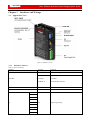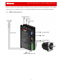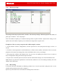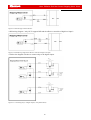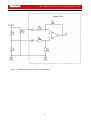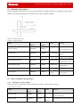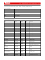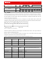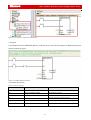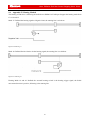
1
Kinco® Kinco FM Series Fieldbus Control Stepping Motor Drive USER MANUAL Shanghai Kinco Automation Co.,Ltd. Kinco FM Series Field bus Control Stepping Motor Drive Kinco® ....................................................................................................................................................................... 1 Chapter 1 Product Overview ............................................................................................................................ 8 1.1 Product Acceptance ......................................................................................................................................... 8 1.2 Product Overview ............................................................................................................................................ 8 1.3 Product Features .............................................................................................................................................. 8 1.4 Product Weight ................................................................................................................................................ 9 1.5 Product Model Description .............................................................................................................................. 9 1.5.1 FM860 Stepping Motor Drive .................................................................................................................. 9 Chapter 2 Precautions and Installation Requirement .................................................................................. 10 2.1 Precaution ................................................................................................................................................ 10 2.1 Environment Conditions .......................................................................................................................... 10 2.2 Mounting Direction & Spacing................................................................................................................ 10 Chapter 3 3.1 Interfaces and Wirings .................................................................................................................. 12 Appearance View ..................................................................................................................................... 12 3.1.1 Interfaces of driver ........................................................................................................................... 12 3.1.2 The X1 and X2 LED definition of FM 860 ..................................................................................... 13 3.2 DIP Switch ............................................................................................................................................... 13 3.2.1 ID Setting up .................................................................................................................................... 13 3.2.2 Communication port Settings .......................................................................................................... 13 3.3 I/O Wiring Diagram ................................................................................................................................. 14 3.4 Communication Connector ...................................................................................................................... 15 3.4.1 CAN ................................................................................................................................................. 15 3.4.2 RS485 .............................................................................................................................................. 16 3.4.3 RS232 .............................................................................................................................................. 16 3.5 FM860 Connecting View ......................................................................................................................... 17 Chapter 4 Using Kinco Stepping PC Software Installing PC Software ...................................................... 18 4.1 Installing PC Software ............................................................................................................................. 18 4.2 Easy Using ............................................................................................................................................... 18 4.2.1 Connecting a PC .............................................................................................................................. 18 4.2.2 How to use Kinco Stepping PC software ......................................................................................... 18 4.3 Operation Your Menu .............................................................................................................................. 22 4.4 How to control your Drive ....................................................................................................................... 23 4.4.1 4.4.2 4.4.3 4.4.4 4.4.5 4.4.6 4.4.7 4.4.8 4.4.9 4.4.10 The Drive Settings ........................................................................................................................... 23 Motor configuration ......................................................................................................................... 23 Current settings ................................................................................................................................ 24 Microstep settings ............................................................................................................................ 25 Basic Setting .................................................................................................................................... 25 I/O Port Settings .............................................................................................................................. 26 Data dictionary ............................................................................................................................... 27 ECAN Setting .................................................................................................................................. 29 Drive Property ................................................................................................................................. 30 Error Control.................................................................................................................................... 30 3 Kinco FMSeries Field bus Control Stepping Motor Driver Kinco FMSeries Field bus Control Stepping Motor Drive 4.4.11 4.4.12 Error History .................................................................................................................................... 31 Initialize/Save .................................................................................................................................. 32 Chapter 5 Operating the I/O Port .................................................................................................................. 33 5.1 Digital signal input .................................................................................................................................. 33 5.1.1 The Polarity control of digital input................................................................................................. 33 5.1.2 Digital signal input address and function......................................................................................... 34 5.1.3 Digital input both for NPN and PNP ............................................................................................... 36 5.2 Digital signal output ................................................................................................................................ 38 5.2.1 The Polarity control of Digital signal output ................................................................................... 38 5.2.2 Digital signal output address and function....................................................................................... 38 5.2.3 Digital output ................................................................................................................................... 39 5.3 Analog signal input .................................................................................................................................. 41 5.3.1 5.3.2 AIN1 common mode voltage input.................................................................................................. 41 AIN1 Differential mode voltage input ............................................................................................. 42 Chapter 6 Operating Mode ............................................................................................................................. 43 6.1 Profile position mode 1 ............................................................................................................................ 43 6.2 Profile velocity mode 3 ............................................................................................................................ 43 6.3 Pulse Control Mode -4 ............................................................................................................................. 44 6.4 Homing Control Mode 6 .......................................................................................................................... 45 6.5 How to simulate velocity mode 3 ............................................................................................................ 45 6.5.1 The index of velocity mode 3 .......................................................................................................... 45 6.5.2 The Process diagram of analog signal ............................................................................................. 46 6.5.3 How to simulate velocity mode 3 without dead zone voltage and offset ......................................... 47 6.5.4 How to simulate velocity mode with dead zone voltage ................................................................. 47 6.5.5 How to simulate profile velocity mode with dead zone voltage and offset ..................................... 48 6.6 Multi-target speed control mode 1 ........................................................................................................... 49 6.6.1 Multi-Target position control ........................................................................................................... 49 6.7 Multi-speed 3 ........................................................................................................................................... 51 Chapter 7 7.1 Communication Function.............................................................................................................. 53 RS232 ...................................................................................................................................................... 53 7.1.1 RS232 Hardware .............................................................................................................................. 53 7.1.2 RS232 Parameters ............................................................................................................................ 53 7.1.3 Free transfer protocol ....................................................................................................................... 54 7.1.4 Data Protocol ................................................................................................................................... 54 7.1.5 RS232 Communication address ....................................................................................................... 56 7.2 RS485 ...................................................................................................................................................... 57 7.2.1 RS485 Communication port ............................................................................................................ 57 7.2.2 RS485 Communication parameters ................................................................................................. 58 7.2.3 MODBUS RTU Communication Protocol ...................................................................................... 58 7.2.4 Modbus Function code .................................................................................................................... 59 7.2.5 Modbus Communication address..................................................................................................... 61 7.3 CANopen Bus communication ................................................................................................................ 61 7.3.1 7.3.2 7.3.3 7.3.4 7.3.5 7.3.6 Hardware introducing ...................................................................................................................... 62 CANopen Communication parameters ............................................................................................ 63 EDS .................................................................................................................................................. 64 SDO ................................................................................................................................................. 64 COB-ID ........................................................................................................................................... 67 PDO: ............................................................................................................................................. 68 4 Kinco FM Series Field bus Control Stepping Motor Drive 7.3.7 7.3.8 7.3.9 7.3.10 Boot-up Process ............................................................................................................................... 69 NMT Module Control ...................................................................................................................... 70 Protection mode(Supervision Type) ........................................................................................... 71 CANopen Communication Address of Stepping Motor Drive Parameters...................................... 72 Chapter 8 Alarm and Troubleshooting .......................................................................................................... 73 8.1 Alarm Messages....................................................................................................................................... 73 Chapter 9 9.1 Appendix......................................................................................................................................... 75 Appendix 1 CANopen Bus communication case..................................................................................... 75 9.1.1 CANopen communication between FM860 and Kinco F1 PLC ..................................................... 75 9.1.2 CANopen Communication between FM860 and Peak CAN ........................................................... 82 9.2 Appendix II RS485 Communication Case............................................................................................... 86 9.2.1 Modbus Communication between FM860 and KINCO HMI ......................................................... 86 9.2.2 Communication between FM860 and Modebus .............................................................................. 88 9.2.3 Modbus Communication Between FM860 and Siemens S7-200 .................................................... 91 9.3 Appendix III RS232 Communication Case ............................................................................................. 93 9.3.1 Communication between FM860 and KINCO HMI........................................................................ 93 9.3.2 The Free Protocol Communication between FM860 and Adjustment tool of Serial port ................ 94 9.3.3 Console wire .................................................................................................................................... 97 9.4 Appendix IV Homing Method ................................................................................................................. 98 9.5 Appendix V Use Stepping Motor Drive PC software to read and write drive ....................................... 101 9.6 Appendix VI Conversion between Engineering unit and internal unit of Common objects .................. 107 9.7 Appendix VII Common Object List ...................................................................................................... 107 FM Stepping Motor Drive User manual Revision History 5 Kinco FMSeries Field bus Control Stepping Motor Driver Kinco FMSeries Field bus Control Stepping Motor Drive Revision Date Description Of Changes 1.0 2013-06-05 Revision 1.0 Preliminary Release 1.1 2013-09-06 Modified the parameters both for diver and motor Added items from 4.4.2 to 4.4.4 6 Safety Precautions For the sake of personal safety and avoidance of property loss, please read these safety precautions carefully before test running and use of the driver. The following safety measures must be strictly followed: After being powered on, the voltage in side FM860 driver is about 70VDC max. The voltage still exists 30 seconds after the power supply is cut off. Before performing any wiring or check operation, use a multimeter to verify that the voltage on the driver terminals is safe; otherwise, the electric shock may occur.. Never connect wires while the driver and the motor are working; otherwise, the electric shock may occur. Do not remove the housing of the driver when the power is on or the driver is working; otherwise, the electric shock may occur. To avoid personal injury and property loss, only qualified and service-trained personnel can operate the driver. Follow related technical specifications and electric installation standards during installation. The driver must be securely grounded with the cross section of the ground cable. Do not insert any object into the driver, which may cause damage to the equipment. If any fault occurs to the driver, please return the driver to the maintenance and repair center. Opening the driver without authorization or improper operation may cause damage to the driver. Removing the enclosure of the driver without authorization will void the warranty. The waste driver shall be disposed of as industrial waste to avoid environmental pollution. Warn When this driver is applied in some mechanical instruments where personal safety is directly involved (e.g. nuclear power control, medical device, truck, train, airplane, amusement and safety devices), be sure to install proper fault-proof devices to avoid the possibility of personal injury. Electronic devices have the appropriate lifecycle. Adequate safety measures must be taken to ensure personal and equipment safety in case of a failure. The users must be liable for any loss resulting from equipment fault or misoperation of the driver. Chapter 1 Product Overview 1.1 Product Acceptance Upon receiving the product, please check the following items: Make sure the driver model is consistent with that ordered. Unpack the product and make sure it is free from damage and no part is missing. Make sure all set screws in the driver are securely tightened. Check the received product against the packing list and contact our customer service center in time if any part is missing. Table1-1 Packing list Packing List article Qty FM860 Stepping Motor Drive 1pcs Services Directory 1pcs FM860 Fieldbus Control Stepping Motor Driver Operating guide Certificate of Conformity 1pcs SCSI 20P connector 1pcs 6P 5mm pitch size terminal block 1pcs length 10mm diameter φ10 Insulated terminals 6pcs length 15mm diameter φ12 Insulated terminals 6pcs Console wiring (RS232 to RJ45) 1pcs 1pcs Note: The console wiring is optional product. If need it please contact our customer service center 1.2 Product Overview FM860 is one of the new Stepping motor drive with field bus control. It cans driving two phase or three phase hybrid stepping motor. As for the heat sink, used new design style. The structure is small and exquisite, and also can meet CE standard requirement. 1.3 Product Features Power supply: 24~70VDC. Support drive two or three phase step motor, output current as 0.1- 6A peak 6 channels opto-isolation digital signal input, and 3 channels of them support wide voltage input as 5~ 24VDC 3 channels opto-isolation digital signal output, max current 100mA Single-channel analog signal input ( ±10V) control the speed. Support multiple pulse input mode, PLS+DIR, CW/CCW and QEI. Support CANOpen and Modbus bus protocol control and optimize the customer's control circuitry. Multi IO configuration to adapt to different control modes. With motor parameter adaptive function, driving motor in the best performance. With the protection function of over-voltage, under-voltage, overheat and over-current. CAN and RS485 (Option), RS232 Kinco FM Series Field bus Control Stepping Motor Drive Micro step :0~128 CE and RoHS 1.4 Product Weight G.W:0.51kg, N.W:0.36 kg. 1.5 Product Model Description 1.5.1 FM860 Stepping Motor Drive Figure 1-1 FM860 Naming rule 9 Kinco FMSeries Field bus Control Stepping Motor Driver Kinco FMSeries Field bus Control Stepping Motor Drive Chapter 2 2.1 Precautions and Installation Requirement Precaution Tightly fasten the screws that fix the motor. Make sure to tightly fasten all fixed points when fixing the driver. Do not tighten the cables between the driver and the motor. Use a coupling shaft or expansion sleeve to ensure that both the motor shaft and equipment shaft are properly centered. Do not mix conductive materials (such as screws and metal filings) or combustible materials (such as oil) into the driver. Avoid the driver and stepper motor from dropping or striking because they are precision equipment. For safety, do not use any damaged driver or any driver with damaged parts. 2.1 Environment Conditions Table 2-1 Environment requirement Environment Condition Operating temperature: 0℃~40℃(Ice-free) Temperature Storage humidity:-10℃~70℃ (Ice-free) Operating humidity: < 90%RH(No condensation) Humidity Storage humidity: < 90%RH(No condensation) Air Height Indoor (No direct sunlight), no corrosive gas or combustible gas, no oil vapor or dust Below 1000m above the sea level Vibration 5.9 m / s 2.2 2 Mounting Direction & Spacing Please install the driver correctly according to following figure, or it will cause faults. The driver should be vertically installed on wall. Take fully into account heat dissipation when using any heating components (such as braking resistors) so that the driver is not affected. 10 Kinco FM Series Field bus Control Stepping Motor Drive Figure 2-1 mounting direction 11 Kinco FMSeries Field bus Control Stepping Motor Driver Kinco FMSeries Field bus Control Stepping Motor Drive Chapter 3 3.1 Interfaces and Wirings Appearance View Figure 3-1 FM860 overview 3.1.1 Interfaces of driver Table 3-1 Jacks introducing Interface Symbol Function SW7~SW10 Communication port Switch X1A(IN) CAN Bus X1B(OUT) Or RS485 Bus interface ID Switch SW1~SW6 ID Switch RS232 X2 RS232 interface X3 Digital signal input Field Bus DIN1+ DIN1DIN2+ DIN2IO DIN3+ DIN3DIN4 DIN5 DIN6 12 Kinco FM Series Field bus Control Stepping Motor Drive COMI AIN1+ AIN1GND Analog signal input and logic voltage interface 5VDC 24VDC OUT1 OUT2 COMO Digital signal output OUT3+ OUT3A+/U A-/V Power supply and Motor wire B+/W connector B- 2 or 3 phase stepper motor cable interface X4 GND Power supply input DC24-70V V+ 3.1.2 The X1 and X2 LED definition of FM 860 Table 3-2 The LED definition Name Color Definition X2 Green Power instructions Orange Receive RS232 Green Send instructions Orange Receiving instructions X1 3.2 3.2.1 DIP Switch ID Setting up Table 3-3 DIP switch settings SW1 SW2 SW3 SW4 SW5 SW6 Node ID OFF OFF OFF OFF OFF OFF EEPROM ON OFF OFF OFF OFF OFF 1 OFF ON OFF OFF OFF OFF 2 ON ON OFF OFF OFF OFF 3 - - - - - - - ON ON ON ON ON ON 63 Note: Pease use the PC software to set and save your parameters when Node-ID is bigger than 63, and all of switch have to be set as OFF. And use the value of EEPROM when it is power-on, but not in value of switch. 3.2.2 Communication port Settings Table 3-4 communication port SW7=ON,SW8=ON RS485 2 wire MODBUS 13 Kinco FMSeries Field bus Control Stepping Motor Driver Kinco FMSeries Field bus Control Stepping Motor Drive RS485 4 wire MODUS SW7=OFF,SW8=OFF DIP switch of termination resistors SW9=ON CAN bus , SW10=OFF, SW9=OFF,SW10=OFF,Disable Enable SW9=OFF,SW10=OFF,Disable SW10=OFF,Enable RS485 bus SW9=ON,SW10=ON,Enable 4 wires 3.3 , SW9=ON 2 wires SW9=OFF,SW10=OFF,Disable I/O Wiring Diagram Figure 3-2 Wiring Diagram Figure 3-3 I/O pins Table 3-5 IO function definition Item X3 I/O SCSI Pin Signal Description Function 1 DIN1+ DIN1+ input High speed digital signal input 2 DIN1- DIN1- input interface 14 Kinco FM Series Field bus Control Stepping Motor Drive 3 DIN2+ DIN2+ input Scope of input voltage: 5~24VDC 4 DIN2- DIN2- input Effective input signal: 5 DIN3+ DIN3+ input >3VDC and >5mA Invalid input signal: <1.5VDC 6 DIN3- DIN3- input Maximum input frequency of optocoupler: 1MHz 11 DIN4 DIN4 input Low speed digital signal input 12 DIN5 DIN5 input interface 13 DIN6 DIN6 input Scope of voltage:12 ~ input 24VDC Effective input signal: > 8VDC 14 COMI The COM input of DIN4,DIN5,DIN6 and >3mA Invalid input signal:<5VDC Max. input frequency of optocoupler:10kHz 3.4 3.4.1 7 AIN1+ AIN1+ Differential input The analog signal input interface 8 AIN1- AIN1- The input impedance:180K 10 GND 9 5VDC 5VDC Logic power output 20 24VDC 24VDC Logic power input 15 OUT1 OUT1 Output 17 OUT2 OUT2 Output 16 COMO 19 OUT3+ Output3+ 18 OUT3- Output-3 Differential input Common port both for AIN1and Logic Max. input frequency:4kHz power Max. withstand voltage:24VDC The maximum output current: 200mA Be logic power input when the Power supply is without input Common output both for OUT1 and Max. output current:100mA OUT2 Max. withstand voltage:24VDC Communication Connector CAN 15 Kinco FMSeries Field bus Control Stepping Motor Driver Kinco FMSeries Field bus Control Stepping Motor Drive Figure 3-4 pins of RJ45 Table 3-6 Coummunication connector definition Item RJ45 Pin Signal Description 1 CAN_H Differential signal 2 CAN_L of CAN 3 GND Signal common X1 4 NC Empty CAN 5 NC Empty 6 NC Empty 7 NC Empty 8 GND Signal common 3.4.2 Function CAN Bus connector RS485 Table 3-7 RS485 Definition Item RJ45 Pin Signal 1 RX 2 /RX 3 GND X1 4 /TX RS485 5 TX 6 NC Empty 7 NC Empty 8 GND Signal common RJ45 Pin Signal Description 1 NC Empty 2 NC Empty 3 TX Transmitted data X2 4 GND Signal common RS232 5 NC Empty 6 RX Received data 7 NC NC 8 NC NC 3.4.3 Description Function Received data Signal common Transmitted data RS485B Bus connector RS232 Table 3-8 RS232 Definition Item Function RS232 Communication connector Notes: 1. The Stepping Motor Drive of FM860 series, do not support CAN and RS485 at the same time. Defined that the model FM860-AA-000 support CAN and FM860-LA-000 build in RS485 only. 2. As for X1 connector of FM860, involves X1A (IN) and X1B (OUT). The function of X1A is same to X1B, and convenient the working of parallel connection by RJ45. 3. RS485 connector has been defaulted as 4-wire Modbus which can use SW7 and SW8 to choose the mode. It will be as 2-wire Modbus If the switch both SW7 an SW8 are ON, otherwise it is 4-wire modbus. 4. Use SW9 and SW10 to choose 120ohm terminal resistance as ON to merge bus and OFF to disconnect if 16 Kinco FM Series Field bus Control Stepping Motor Drive Drives are on the end of Bus. Please use SW9 to set up it if the drive with CAN function. As for RS485 connector, there are 2 kind of mode as 2-wire mode using SW9 and 4-wire mode using SW9 and SW10. 3.5 FM860 Connecting View Figure 3-5 FM860 Over view 17 Kinco FMSeries Field bus Control Stepping Motor Driver Kinco FMSeries Field bus Control Stepping Motor Drive Chapter 4 4.1 Using Kinco Stepping PC Software Installing PC Software Installing PC Software Please access www.kinco.cn to download Kinco Stepping PC Software and unzip to use directly. 4.2 4.2.1 Easy Using Connecting a PC You have to use Kinco Stepping PC software to set up the parameter by RS232 or CAN connector. Please refer chapter 3 to connect Stepping Motor Drive and Motor before using. How to connect FM860 Stepping motor drive from RS232 to PC? Prepare 24VDC logic voltage, console wire first, and refer the connecting as following. PC Desub RS232(RJ45 connector) RXD (2) --------------------------------- TXD (3) TXD (3) --------------------------------- RXD (6) GND (5) --------------------------------- GND (4) How to connect the drive from CAN to PC as FM860? You need to have 24V logic voltage, PEAK series USB or LPT adapter. CAN communication cable, needn’t power supply external. Pecan Desub CAN (RJ45 connect) CAN_L (2)----------------------------------- CAN_L (2) CAN_H (7) ----------------------------------- CAN_H (1) GND (3) ----------------------------------- GND (3) 4.2.2 How to use Kinco Stepping PC software 1. Click the Kinco Stepping PC software folder and find the icon as Kincostep open the software as following picture. 18 , and double click it to Kinco FM Series Field bus Control Stepping Motor Drive Title bar Menu bar Toolbar 2. Click File->New. 19 Kinco FMSeries Field bus Control Stepping Motor Driver Kinco FMSeries Field bus Control Stepping Motor Drive 3. It will popup a dialog as following picture. Please click RS232 if the communication type is serial port, then click the Next. Click CAN if you use PECAN and press Next key. 4.Then it will show us a dialog as following to set up COM, baud rate, ID and click the Red communication button . 20 Kinco FM Series Field bus Control Stepping Motor Drive 5.Set CAN parameters in following window if you use PECAN.Follows are default parameters. 6. Check whether there is Comm Status: Open COM1 38400 on the right-bottom and the light of Comm Status has turned on in green. If yes, it is connecting successful. For CAN, it will show us Comm Status: Open 500K Bit/S, and the light is also in green if accessed successful. 21 Kinco FMSeries Field bus Control Stepping Motor Driver Kinco FMSeries Field bus Control Stepping Motor Drive 4.3 Operation Your Menu Click Kinco Stepping PC software, and it will open a window as following: Title bar Menu bar Toolbar As for such window, you can set up your drive and motor via menu bar. And the details of menu bar are as follows. Table 4-1 Menu bar introducing Item Function description File New tasks, Open old file, Save Communication Setting up the communication way and parameter from drive to PC. Drive Control the Drive, refer to Item 4.4 for details. Motor To set up the parameter. Operation Mode Homing mode Extend Support the language both for English and Chinese, and the function as read, write. Please refer the detail as appendix. 22 Kinco FM Series Field bus Control Stepping Motor Drive 4.4 4.4.1 How to control your Drive The Drive Settings The dialog can be set for your Drive as for the User-secret. And you also can right click to get help. 4.4.2 Motor configuration If you prefer to select Software to create motor parameters, please download KincoStep software from www.kinco.cn first, and use console wire(with the connector from RS232 to RJ45) software and run it. 23 to connect your Kinco FMSeries Field bus Control Stepping Motor Driver Kinco FMSeries Field bus Control Stepping Motor Drive There are 3 kinds of methods for user to set up motor parameters. 1.Automatic detection of motor parameters Follows are the default value for the motor parameters: Motor type : MC Motor phase: 2 Motor phase current: 3A (Arms) Motor_test_switch: 1 Driver setting is defaulted as 2 phase, the LED will show error if you use 3 phase motor actually. So, please change the phase according to the actual phase of motor. 2. Select motor type User also can select the right motor type if you don’t like to use automatic detection of motor parameters, then the parameters will be listed into the dialog by automation. As for the motor type, you can select motor type first, then right click to find the help and click it, then you will see the motor type list. 3)User defined(Motor type as XX) If you selected the motor which are not in the list, please set motor type as XX, then set the motor parameters by manual. 4.4.3 Current settings As for factory settings of Motor phase current, defaulted as 3A (Arms)/4.2A(peak). General, the scope of the current is from 0A(Arms)/0A(Peak)~4.3(Arms)/6A(Peak), which can change by user. It needs to save motor parameters and reboot driver after you modified the value. Please contact Manufacturer if you need the driver which current is over default value. 24 Kinco FM Series Field bus Control Stepping Motor Drive 4.4.4 Microstep settings The setting of microstep in pulse mode (-4 mode),The microstep settings : Microstep equal to the number of pulses per revolution/(360°/ Step angle) Note: The number of pulses per revolution must lager than or equal to 200 for 2 phase motor setting. As for 3phase motor, the number of pulses per revolution must larger than or equal to 300. Example 4-1: How to create your password via Kincostep PC software 1. In the window of Drive Configuration, write the password as 1234 (the password range is from 1 to 65535) 2. Click Save control parameters in the Initialize/save of Drive on the toolbar. And need to click save motor parameters if the motor has changed also, then click Reboot drive to save your change. 3. The password is effective after Reboot drive. So you can’t do anything for the drive, have to return to Drive Configuration dialog and write the password first. 4. If you want to cancel the password, need to write the old first then change it to 0 and click Reboot drive. Note: Please set up the motor parameters at the first time, otherwise it can’t be running normally, due to the default value with motors. 4.4.5 Basic Setting It can know the basic information as following window. So we can do some basic setting for drive. As for related mode operation, please refer to chapter 6. By the way, the window also can monitor the running status of the drive. 25 Kinco FMSeries Field bus Control Stepping Motor Driver Kinco FMSeries Field bus Control Stepping Motor Drive Example 4-2:How to operate the Speed-Demand via Kincostep PC software 1. Follow example 4-3 and open I/O port. Set DIN1 as Drive enable, DIN2 as Fault reset, DIN3 as Operation mode. 2. Refer to chapter 6.2 profile velocity mode to set up the parameters as the window shown us the speed is 100RPM. And change the value of speed as negative if you want to run it reverse. 4.4.6 I/O Port Settings As following window, defaulted by system, it allow to change the I/O function, polarity. More details please refer to example 4-3. Example 4-3 How to configure I/O via Kincostep PC software 26 Kinco FM Series Field bus Control Stepping Motor Drive Set DIN1 as Drive enable, DIN2 as fault reset, DIN3 as operation mode, DIN4 as positive limit, DIN5 as negative limit, DIN6 as star homing. 1. As following picture, click button to show us a list and select the item we want and click OK to finish it. 2. Follow step1 to operate the I/O port and finish as below. 4.4.7 Data dictionary You can get the index and detail information of all FM Series in the data dictionary. As shown in following picture, left side includes information of index, sub-index and naming of CANopen.Right side is the details of the parameters. 27 Kinco FMSeries Field bus Control Stepping Motor Driver Kinco FMSeries Field bus Control Stepping Motor Drive Example 4-4 How to add a index and setting it Let’s learn how to add an index into Basic operation list and setting it. Now we add CANopen Baud rate. 1. Right click in the Basic operation list and choose Add, then it will popup a window of Data Dictionary such as the picture. 2. Input CAN and click Find next, it will jump to 2F81, and to know more information on the right side. 3. Double click the index 2F81, the index will be added into the menu list successful as below. 28 Kinco FM Series Field bus Control Stepping Motor Drive 4. How to cancel the index in the menu list? Find it and click your PC on the right then click del to finish it. If want to know more information about a index, find it and click your PC mouse then click help. 4.4.8 ECAN Setting As for this menu list,it can set the communication parameters of CANopen. please refer to chapter 7.3. 29 Kinco FMSeries Field bus Control Stepping Motor Driver Kinco FMSeries Field bus Control Stepping Motor Drive 4.4.9 Drive Property We can know the information of drive such as software version, S/N and so on in the window. 4.4.10 Error Control This menu will show the error status if there is any error. In the menu, the code of 16 hex is the error code, and the box is used to select whether the alarm is shielded or not. The light will turn red if there is error, 30 Kinco FM Series Field bus Control Stepping Motor Drive more details please refer to chapter 8. Note: Untick the box to shield the error if you need,but some of errors can’t shield. 4.4.11 Error History As for FM860 Stepping motor Drive, there are 7 groups of historical error information. In following picture,Error-point is the number of the pointer for current error. Error-history [N] means the current error at the [N]. As for last error record, is N -1 (for example, N is 4, the last error record is 4-1=3, the value is 3), the next error record is N+ 1. There are 8 error-history. 31 Kinco FMSeries Field bus Control Stepping Motor Driver Kinco FMSeries Field bus Control Stepping Motor Drive 4.4.12 Initialize/Save The menu provides save parameters, initialize control parameters and reboot drive. Pay attention to that motor parameters is saved separately. 32 Kinco FM Series Field bus Control Stepping Motor Drive Chapter 5 Operating the I/O Port As for FM860, there are 6 channels digital input, 3 channels digital output. Both for digital input and output setting is flexible. You can set up the function of I/O as the real requirement. 5.1 Digital signal input 5.1.1 The Polarity control of digital input Now, make S1 as open or close to change the polarity of IO via Kincostep PC software. It means the polarity is open if the light is in green, the DIN1 is un-working. Example 5-1, How to set up the digital signal input as DIN1 Figure 5-1 Polarity settings of digital signal input as DIN1 1. Kincostep PC software has running in FM860 successful. 2. Open I/O window. And click DIN4 and DIN5 polarity light which will become in red, now DIN4 and DIN5 is close, then DIN1 is effective. Figure 5-2 Digital I/O View of PC Software 33 Kinco FMSeries Field bus Control Stepping Motor Driver Kinco FMSeries Field bus Control Stepping Motor Drive 5.1.2 Digital signal input address and function Table 5-1 Digital signal input function and default value NAME FUNTION Value DIN1_Function Pulse input 01(Pulse) Direction input Clockwise pulse input DIN2_Function Counterclockwise pulse input 02(Direction input) Quadrature encoder phase A input Quadrature encode phase B input DIN3_Function Quadrature encoder index input 03(motor free) Motor free Drive enable DIN4_Function Fault reset 04(NULL) Quick stop Reverse speed demand DIN5_Function Positive limit 05(NULL) Negative limit Homing signal DIN6_Function Start homing 06(NULL) Multi-speed 0 Multi-speed 1 Multi-speed 2 Multi-speed 3 Multi-position 0 Multi-position 1 Multi-position 2 Multi-position 3 Set-point active Operation mode Table 5-2 Meaning of digital signal input Function Meaning Pulse input In the mode as pulse plus direction, the pulse signal Note: input Only DIN1 and DIN2 can Direction input In the mode as pulse plus direction, the direction signal input Clockwise pluse input In double-pulse mode, the CW pulse input as clockwise Counterclockwise pulse input In double-pulse mode, the CW pulse input as counterclockwise Quadrature encoder phase A Incremental encoder mode,A phase signal input input 34 support these functions. Kinco FM Series Field bus Control Stepping Motor Drive Quadrature encode phase B Incremental encoder mode,B phase signal input input Quadrature encoder index Incremental encoder mode,Z phase signal input input Motor free Motor off, and motor axis is loose in avail status Drive enable Drive enable, control word in avail status can be configured via object 202033 to input control word Fault reset Clear error alarm, the rising edge of the signal is detected Quick stop When the signal is valid, the motor shaft releases. After the signal is removed, the drive requires re-enabling. Reverse speed demand To reverse the target speed in the speed mode. Positive limit Indicates the limit of forward running of motors (normally closed by default. the drive regards position positive limits as valid, and polarity can be modified to adjust to normally open switches. Negative limit Indicates the limit of inverted running of motors (normally closed contact by default. the drive regards position negative limits as valid, and polarity can be modified to adjust to normally open switches.) Homing signal Homing switch signal Start homing Star the command of homing, the rising edge of the signal is detected. Multi-speed 0 Multi-speed 1 Using it to control the switch of multi-position. Input signal 3-0 to consist a number Multi-speed 2 in hex. Multi-speed 3 Multi-position 0 Used to switch Multi-position. Input signal as 4bits from 3-0 to consist a number in Multi-position 1 hex. Multi-position 2 Multi-position 3 Set-point active Create target-position or position segment, the ring edge of the signal is avail. Operation mode To switch 2 kind of mode. The mode of valid signal and invalid can be defined as flexible. Need to via object 202031 input operation mode and select 0 and the object 202032 to select 1 to configure. Example 5-2 How to set up drive enable by PC software As following picture, click button to show us a list and find the item we want and click OK to finish it. 35 Kinco FMSeries Field bus Control Stepping Motor Driver Kinco FMSeries Field bus Control Stepping Motor Drive Figure 5-3 I/O function setting Example 5-3 How to set up pulse input As for the pulse input function, it is supported both for DIN1 and DIN2 support only. If DIN1 is pulse input, DIN2 will be as direction input if DIN1 have the signal as pulse input, and DIN2 can not be as NULL. Otherwise it will not work. Figure 5-4 I/O function setting 5.1.3 Digital input both for NPN and PNP 1.NPN Wiring Diagram(Support the effective controller of low level output) 36 Kinco FM Series Field bus Control Stepping Motor Drive Figure 5-5 NPN Wiring 2. PNP Wiring Diagram(Support the effective controller of high level output) Figure 5-6 PNP Wiring 37 Kinco FMSeries Field bus Control Stepping Motor Driver Kinco FMSeries Field bus Control Stepping Motor Drive 5.2 Digital signal output 5.2.1 The Polarity control of Digital signal output The polarity of digital output is defaulted as open. About how to change the polarity please refer to example 5-1. 5.2.2 Digital signal output address and function Table 5-3 Digital signal output and default function Name Function Value DOUT1_Function Ready 01 (read) Error DOUT2_Function Position reached 02 (error) Zero velocity Motor brake DOUT3_Function Velocity reached 03 (NULL) Index signal Max velocity limit PWM ON Position limiting Reference found Index signal frequency Absorb voltage Table 5-4 Meaning of Digital output signal function Function Meaning Ready Drive is on operation mode Error Alarm status Position reached In position mode, target-position data is no change from position to time window. And while the position error in the position to the window. Zero velocity Motor velocity is zero after motor enable Reserved Function is pending Velocity reached Motor speed reached the target in the control of speed mode Reserved Function is pending Reserved Function is pending PWM ON Drive enable motor Position limiting Motor is in limit Reference found End of homing Index signal frequency Index signal seems to be homing, and set output periodic pulse. Absorb voltage To absorb the main voltage, used as 3 phase driver and connecting resistor between V+ and B- Example 5-5 How to set Driver ready 38 Kinco FM Series Field bus Control Stepping Motor Drive 1.Connect Kincostep PC software to FM860. 2. Open I/O window. And click the button as in DIN1, and find ready and mark it in the list as following Figure 5-7 Drive standby 5.2.3 Digital output 1 Digital output wiring diagram Figure 5-8 internal diagram of digital output 2.NPN wiring diagram(OUT1-OUT3 support NPN and the effective controller of low level input) 39 Kinco FMSeries Field bus Control Stepping Motor Driver Kinco FMSeries Field bus Control Stepping Motor Drive Figure 5-9 NPN Wiring(Common cathode) 3.PNP wiring diagram(only OUT3 support PNP and the effective controller of high level input) Figure 5-10 PNP Wiring (Support the effective controller of high level input) 4. Follow the diagram as below to connect relay to the digital output. Figure 5-11 Connecting relays on digital output ( Anti-parallel diode) 40 Kinco FM Series Field bus Control Stepping Motor Drive 5.3 5.3.1 Analog signal input AIN1 common mode voltage input Figure 5-12 Common mode input voltage wiring diagram 41 Kinco FMSeries Field bus Control Stepping Motor Driver Kinco FMSeries Field bus Control Stepping Motor Drive 5.3.2 AIN1 Differential mode voltage input Figure 5-13 Differential mode input voltage wiring diagram 42 Kinco FM Series Field bus Control Stepping Motor Drive Chapter 6 6.1 Operating Mode Profile position mode 1 Now make an example to explain this mode. Coordinate system as shown below, the red arrow is defined as the current position 450, if we make the absolute position movement, when the target position is set to 700, the motor will run to coordinate position of 700 ; if we make a relative position movement, when the target position is set to 700, the motor will run to the coordinate position of 1150.(Now make a example to explain this mode. The Coordinate system, as to the red arrow is defined as the current position is 450, if we make the absolute position movement, when the target position is set to 700, the motor will run to Coordinate the position of 700; If we make a relative position movement, when the target position is set to 700, the motor will run to the coordinate position of 1150.) Figure 6-1 Absolute/ Relative position Table 6-1 Objects in Mode 1 CANopen Modbus address address Operation_Mode 60600008 0x3500 1 Profile_Speed 60810020 0x4A00 User Setting speed of trapezoidal curve Profile_Acce 60830020 0x4B00 User Setting Profile_Acce Profile_Dece 60840020 0x4C00 User Setting Profile_Dece Pos_Target 607A0020 0x4000 User Setting target position Write 2F first Absolute position is running then Motor then 3F Begin run. Write 4F first Relative position is running then Motor begin run. Name Control Word 60400010 0x3100 Value Meaning To set up operation mode as absolute position mode and relative position. then 5F According to the change of target position, begin 103F absolute position moving immediately. Please refer Appendix VII for more information. And read chapter 9 if want to know how to set up profile position mode by communication or I/O to finish it. 6.2 Profile velocity mode 3 As for the mode 3, can running for the speed control of Motor. The running curve involves 3 phase as accelerating, uniform speed and speed reduction. The time of accelerating can figure out by initial velocity, Uniform speed and accelerated speed as below. 43 Kinco FMSeries Field bus Control Stepping Motor Driver Kinco FMSeries Field bus Control Stepping Motor Drive Vt=Vo+at Vt-Uniform speed Vo-Initial velocity a –Accelerated speed or depend reduction t - Acceleration time S=Vot + (1/2) at2 S-Accelerated segment displacement Figure 6-2 The curve both for speed and time of Mode3 Table 6-2 Objects in Mode 3 CANopen Modbus address address Operation_Mode 60600008 0x3500 Speed_Demand 60FF0020 0x6F00 Profile_Acce 60830020 0x4B00 Profile_Dece 60840020 0x4C00 Name Control_Word 60400010 0x3100 Value Meaning 3 operation mode of drive User Settings target speed User acceleration of trapezoidal curve acceleration of Settings trapezoidal curve User Settings write 6 first then F acceleration of trapezoidal curve Lock the motor shaft, write such parameters and run it as the parameter request. And motor will re-run after you write new speed value Please refer Appendix VII for more information. And read chapter 9 if want to know how to set up profile velocity mode by communication or I/O port to finish it. 6.3 Pulse Control Mode -4 The motor running is monitored by X3 port of Drive in the mode -4. And the index is as below. Table 6-3 Objects in Mode -4 CANopen Modbus address address Operation_Mode 60600008 0x3500 -4 microstep 64101810 0x7180 User Setting the number of pulses per motor revolution Control_Word 60400010 0x3100 F Lock motor, motor begin to move. Name Value Meaning Set up operation mode to be pulse control mode Note: Please re-define the IO port both for DIN1 and DIN2 as example of 5-3. And refer Appendix VII for more information about the index of objects. 44 Kinco FM Series Field bus Control Stepping Motor Drive 6.4 Homing Control Mode 6 It must define the homing before you do the localization of absolute position. As following picture shown that have to define the homing as 0, 0 before locate X and Y=100mm, 200mm. Figure 6-3 Homing control mode Table 6-4 Objects in mode 6. CANopen Modbus address address Operation_Mode 60600008 0x3500 6 homing mode 60980008 0x4D00 User Setting Home_Offset 607C0020 0x4100 User Setting Homing_Speed_Switch 60990120 0x5010 User Setting Homing_Speed_Zero 60990220 0x5020 User Setting Homing_Accelaration 609A0020 0x5200 User Setting Homing Accelaration Control_Word 60400010 0x3100 Write F first Lock the 1F begin to move. NAME Value Meaning operation mode of drive is homing mode method for searching homing offset after homing velocity for searching homing switch signal velocity for searching homing signal motor, motor Please refer Chapter 9 to know how to control homing mode. 6.5 How to simulate velocity mode 3 6.5.1 The index of velocity mode 3 The motor running is handled by X3 port of Drive in this mode. And the index is as below. Table 6-5 Objects in mode 3 CANopen Modbus address address Operation_Mode 60600008 0x3500 Analog 1_Filter 25020110 0x1610 NAME 45 Value 3 User Setting Meaning Operation mode of drive is target speed control mode. filter parameter of analog signal as Kinco FMSeries Field bus Control Stepping Motor Driver Kinco FMSeries Field bus Control Stepping Motor Drive f=4000/(2π*Analog1_Filter) time constant: τ= Analog1_Filter/4000(S) Analog 1_Dead 25020210 0x1620 Analog1_Offset 25020310 0x1630 analog1_out_polarity analog_speed_rpm at 10V 25021410 25021310 0x1740 0x1730 User Setting User Setting User Setting dead space of analog signal 1 offset of analog signal 1 polarity of analog output 0: The same as the input polarity 1: In contrast to the input polarity User Analog 10V speed, it is without Setting dead and offset. Analog signal control speed, valid at operation mode 3 0x0: not valid Analog_Speed_Con 25020708 0x1670 User 0x1: speed controled by analog Setting signal 1 0x10…0x1f: Ain1 control the "target speed control[x-0x10]" Profile_Acce 60830020 0x4B00 Profile_Dece 60840020 0x4C00 Control_word 60400010 0x3100 User Setting User Setting F acceleration of trapezoidal curve acceleration of trapezoidal curve Lock motor, motor begin to move. More details please refer Appendix VII. 6.5.2 The Process diagram of analog signal Figure 6-4 Analog signal process Table 6-6 Variable of analog signal Variable Meaning Scope U internal External voltage is same to internal -10V~10V 46 Kinco FM Series Field bus Control Stepping Motor Drive data. Without offset and dead zone voltage, the scope is from -2048 to 2047. Uexternal Power supply voltage -10V~10V Ushift offset voltage the scope of 0~10 is 0~8191 Udead Dead zone voltage The scope of 0~1 is 0~8191 6.5.3 How to simulate velocity mode 3 without dead zone voltage and offset Requirement: Choose DIN1 as drive enable, DIN2 as fault, 无限位开关。And 10V is at rated 1000rpm, -10V is at rated -1000rpm. As for the speed, controlled by analog signal 1 as AIN1. Table 6-7 Parameter settings NAME Operation_Mode CANopen Modbus address address 60600008 0x3500 Value 3 Meaning Operation mode of drive is target speed control mode. filter parameter of analog signal as f=4000/ Analog 1_Filter 25020110 0x1610 5 (2π*Analog1_Filter) time constant: τ= Analog1_Filter/4000(S) Analog 1_Dead 25020210 0x1620 0 dead space of analog signal 1 Analog1_Offset 25020310 0x1630 0 offset of analog signal 1 polarity of analog output analog1_out_polarity 25021410 0x1740 0 0: The same as the input polarity 1: In contrast to the input polarity analog_speed_rpm at 10V 25021310 0x1730 1000 10V speed of Analog signal 1, is same to the speed without dead and offset. Analog signal control speed, valid at operation mode 3 Analog_Speed_Con 25020708 0x1670 1 0x0: not valid 0x1: speed controlled by analog signal 1 0x10…0x1f: Ain1 control the "target speed control[x-0x10]" Profile_Acce 60830020 0x4B00 9830 acceleration of trapezoidal curve Profile_Dece 60840020 0x4C00 9830 acceleration of trapezoidal curve Store_Data 2FF00108 0x2910 1 1:Store the parameters un-involves Motor. 10:initialize the parameters un-involves motor 6.5.4 How to simulate velocity mode with dead zone voltage Requirement: -0.5V~0.5V are dead zone voltage, means the speed is 0 during the voltage from -0.5V~0.5V. And 10V is at 1000rpm, -10V is at -1000rpm. 47 Kinco FMSeries Field bus Control Stepping Motor Driver Kinco FMSeries Field bus Control Stepping Motor Drive Use analog channel 1 as AIN1 to control speed. Figure 6-5 Control speed diagram 1 In fact the speed of 10V is 950rpm (=(10V-0.5V)/10V*1000rpm) duo to the dead zone voltage. Base on chapter 6.5.3, the index have to change as below Table 6-8 Parameter of Analog 1 Name Dead zone of analog input 1 6.5.5 CANopen Modbus address address 25020210 0x1620 Value 0.5V(=410DEC) Meaning Dead zone voltage of external analog signal 1 How to simulate profile velocity mode with dead zone voltage and offset Requirement: offset voltage is 1V, Dead zone is 0.5V-1.5V, 10V 对应 1000rpm. And choose analog channel 1 as AIN1 control speed. Figure 6-6 Speed mode diagram 2 In fact the speed of 10V is 850rpm (=(10V-1V-0.5V)/10V*1000rpm), 48 -10V is 1050rpm Kinco FM Series Field bus Control Stepping Motor Drive (=(-10V-1V+0.5V)/10V*1000rpm) duo to the dead zone and offset voltage. Base on 6.5.3, the index have to change as below. Table 6-9 parameters 2 in analog 1 CANopen Name Dead zone of analog input 1 offset of Analog input 1 6.6 Modbus address Value 25020210 0.5V(=410DEC) 410 25020310 1V(=819DEC) 819 address Meaning Dead zone voltage of external analog signal 1 offset voltage of external analog signal 1 Multi-target speed control mode 1 As for multi-target speed control mode is active the target position to control motor by input port. And there are 3 items to active it as below. 1. Multi-target speed control can run in 1 mode only. 2. The index to simulate provide velocity mode is 0, and at the same time, speed channel is invalid. 3. At least, there is 1 input port that defined multi-target position control as 0/1/2/3”. Please input 0,1,2,3 which will be constituted the codes of binary system and selected as multi-target speed control from 0--15 channel, and the list as below. Table 6-10 Binary system code Multi-position Multi-position 3 Multi-position 2 Multi-position 1 0 Din_Position Din_Speed 0 0 0 0 0 0 0 0 0 1 1 1 0 0 1 0 2 2 0 0 1 1 3 3 0 1 0 0 4 4 0 1 0 1 5 5 0 1 1 0 6 6 0 1 1 1 7 7 1 0 0 0 8 8 1 0 0 1 9 9 1 0 1 0 10 10 1 0 1 1 11 11 1 1 0 0 12 12 1 1 0 1 13 13 1 1 1 0 14 14 1 1 1 1 15 15 Note: The signal is defaulted as 0 if do not select input signal 0,1,2,3 for multi-target position. 6.6.1 Multi-Target position control As for Motor, need to move 7 points position and request that the speed in 0 point position is 100prm to arrive the pulse of 5000. 49 Kinco FMSeries Field bus Control Stepping Motor Driver Kinco FMSeries Field bus Control Stepping Motor Drive For the speed in 1 to 7 point position, is 150rpm, 175prm, 200rpm, 300rpm, 325rpm, 275rpm and 460rpm speed to the pulse as15000, 28500, -10500, -20680, -30550, 850, 15000 respectively. Table 6-11 I/O Settings Item Value DIN1 Drive enable DIN2 Operation mode DIN3 Set-point active DIN4 Multi-position 0 DIN5 Multi-position 1 DIN6 Multi-position 2 Table 6-12 Position and speed settings CANopen Modbus address address Din_Pos 0 20200120 Input multi-speed 0 Name Value Meaning 0x0C10 5000 Multi-position 0 20201120 0x0D10 100 Multi-speed 0 Din_Pos 1 20200220 0x0C20 15000 Multi-position 1 Din_Speed 1 20201220 0x0D20 150 Multi-speed 1 Din_Pos 2 20200320 0x0C30 28500 Multi-position 2 Din_Speed 2 20201320 0x0D30 175 Multi-speed 2 Din_Pos 3 20200420 0x0C40 -10500 Multi-position 3 Din_Speed 3 20201420 0x0D40 200 Multi-speed 3 Din_Pos 4 20200520 0x0C50 -20680 Multi-position 4 Din_Speed 4 20201520 0x0D50 300 Multi-speed 4 Din_Pos 5 20200620 0x0C60 -30550 Multi-position 5 Din_Speed 5 20201620 0x0D60 325 Multi-speed 5 Din_Pos 6 20200720 0x0C70 850 Multi-position 6 Din_Speed 6 20201720 0x0D70 275 Multi-speed 6 Din_Pos 7 20200820 0x0C80 15000 Multi-position 7 Din_Speed7 20201820 0x0D80 460 Multi-speed 7 20203810 0x0F80 10 Din_Mode0 20203108 0x0F10 1 Din_Mode 1 20203208 0x0F20 1 Din_Control_Word 20203310 0x0F30 2F Profile_Acce 60830020 0x4B00 50 set the acceleration (rps/s) Profile_Dece 60840020 0x4C00 50 set the deceleration (rps/s) Multi-speed/ Position switching delay 50 Multi-speed/Effective input delay after changed position Input control Mode, low level mode. Input control Mode, low level mode. IInput enable signal control_Word as Kinco FM Series Field bus Control Stepping Motor Drive 1:save the parameterss without Store_Data 2FF00108 0x2910 Motor 1 10:initialize the parameterss without motor Note: the unit of multi-position is step, and for multi-speed and acceleration is rpm and rps/s, all of them changed to the unit of DEC with communication. The steps of operation are as following. 1. Input enable to the drive. 2. Select the line position you want to move. And changed DIN4, DIN5, DIN6 level. 3. Set the active point and run the program. 6.7 Multi-speed 3 In generally, selected input signal to active target-speed to control motor. There are 3 item about it. 1. Multi-position control running is in 1 mode only. 2. The index to simulate speed control is 0, and the speed control channel is invalid. 3. At least, there is one input signal channel which defined multi-speed control 0/1/2/3. Please input 0,1,2,3 which will be constituted the codes of binary system and selected as multi-target speed control from 0--15 channel, and the list as below. Table 6-13 Binary system code Multi-speed control 3 Multi-speed control 2 Multi-speed control 1 Multi-speed control 0 Input speed control 0 0 0 0 0 0 0 0 1 1 0 0 1 0 2 0 0 1 1 3 0 1 0 0 4 0 1 0 1 5 0 1 1 0 6 0 1 1 1 7 1 0 0 0 8 1 0 0 1 9 1 0 1 0 10 1 0 1 1 11 1 1 0 0 12 1 1 0 1 13 1 1 1 0 14 1 1 1 1 15 Note: The signal is defaulted as 0 if do not select input signal 0,1,2,3 for multi-target position. The parameter of multi-speed control 0-15, can select by IO port, and also will be achieved by analog signal to control it. The parameters of analog speed will be covered by the value of using analog signal. 51 Kinco FMSeries Field bus Control Stepping Motor Driver Kinco FMSeries Field bus Control Stepping Motor Drive Table 6-14 Parameter setting of multi-speed Name CANopen address Modbus address Value Meaning select the channel of analog speed 0: not valid 1: AIN1, valid channel Analog_Speed_Con 25020708 0x1670 1x 0x10…0x1f: Ain1 control the "target speed control[x-0x10]" is avalid 52 Kinco FM Series Field bus Control Stepping Motor Drive Chapter 7 Communication Function FM860 Stepping Motor Drive used 3 types protocol as CANopen and RS485 Modbus protocol and CANopen. The solution of selected controller as KINCOstep PC software to communicate to control drive in the field as uniaxial and multiaxial system replaced the old operation as pulse direction mode. And good at the points as reduce noise, cost down and so on. Please pay attention as below if you selected FM860. 1. The I/O port DIN1 is defaulted as pulse input, DIN2 as direction input, DIN3 is motor free. Cancel the I/O settings by software if use communication control. 2. The index involves 2 types unit both for National standards and customized which can define by user’s habit. Do not forget convert the unit to DEC when you write and read. And refer appendix VII to know more. 3. Take care command interval when use CANopen SDO to read/write and RS232 and RS485 to control. Make sure that only 1pcs drive send message at the same time and do the best for communication error, avoid the endless loop. 4. Some of index bit are out of size. In fact you can do not use it in real running. The index has the defaulted value for out of size part. For example, the motor don’t accept the high speed duo to the target speed is 32bit. So the drive is limited the max value as 24576000(1500rpm), be the default value. 7.1 RS232 7.1.1 RS232 Hardware How to connect from FM860 to PC, HMI PC Desub FM860 X2 (RJ45 connector) RxD (2) --------------------------------- TXD (3) TxD (3) --------------------------------- RXD (6) GND (5) --------------------------------7.1.2 GND (4) RS232 Parameters Table 7-1 Communication parameters Name CANopen Modbus address address Value Meaning drive ID set by DIP switch or PC software ID_Com 0x100B0008 0x0600 1 注:1) ID switch: SW6-SW1, select 1~63 or Ox2FE400 select 1~127。 2) Store and reboot the parameters if updated. ID node is from 1 to127; node_id_offset 0x2FE40008 0x2800 127 Note: the setting is valid when SW6-SW1 is on OFF. And Store and reboot the parameters if updated. 53 Kinco FMSeries Field bus Control Stepping Motor Driver Kinco FMSeries Field bus Control Stepping Motor Drive For RS232 Baud rate setting RS232_Baud rate 0x2FE00010 0x2400 520 Value Baud rate 2082 4800 1041 9600 520 19200 259 38400 86 115200 Need to reboot Store the parameter of control loop 0x2FF00108 0x2910 1:Store the parameter which changed. 1 10: Initialize the parameters which updated 7.1.3 Free transfer protocol RS232 follow up the protocol both for master and slave. PC can send any message to Stepping Motor drive, and the drive which set address will return a message after calculated these data. The formatting of RS232 transfer protocol is 10bytes. byte 0 byte 9 ID 8 byte data CHKS ID Com: Slave address CHKS =-SUM(byte0,…,byte8),CHK: The last 2bit PC sending: byte 0 ID byte 9 8 byte host data CHKS PC receive(returned from FM860) : byte 0 ID byte 9 8 byte slave data CHKS Note: Each 10bytes has a CHKS. There isn’t any return from FM860 if you send an error address which is not in the list. And the slave will find the address and check it out to you. The slave will do not reply to if the address is different with master’s. 7.1.4 Data Protocol Data protocol is different with transfer. The content of Data protocol is the 8 bytes middle of the 10bytes of transfer protocol. All value and function is shown by index and sub-index. The formatting are download and upload. A:Download, means master write value to the object of slave, then will be error if download on the address which do not in the list. Table 7-2 Master send message 10.5 Byte1 Byte2 Byte3 Byte4 Byte0 54 Byte5 Byte6 Byte7 Kinco FM Series Field bus Control Stepping Motor Drive CMD INDEX SUB INDEX DATA CMD Specified the data transfer direction and data size. 0x23 Send 4bytes of data (bytes 4...7 involves 32bits) 0x2b Send 2bytes of data (bytes 4,5 includes 16bits) 0x2f Send 1bytes of data (bytes 4 includes 8bits) INDEX The address of send object SUB-INDEX The address of send sub object The order of the 4bytes the data is from low to high. For example, write 7650DEC, 607A0020 inc. and 7650 is 10 hex, 1DE2 is 16 hex. The object is required 4 bytes, the result of value is only 2bytes as 1D E2. so can add 0 on the hight position as 00 00 1D E2. DATA: byte4=E2 byte5=1D byte6=00 byte7=00 Table 7- 3 Slave returned Byte0 Byte1 Byte2 RES INDEX Byte3 Byte4 SUB INDEX RESERVED RES: Show the return of slave 0x60 Message send out successful 0x80 Error,figure out from the byte as 4…7 INDEX 16bytes address same to master Byte5 Byte6 Byte7 SUBINDEX 8bytes address same to master RESERVED Backup For example: Master send download order to slave: 01 23 7A 60 00 E2 1D 00 00 03 (The order written to the target position of slave as 607A0020) Slave return: 01 60 7A 60 00 E2 1D 00 00 C6 Meaning: 01-Slave address 60-the data bytes of transfer is 2bytes, saved by save byte4…byte5 byte4=E2,byte5=1D,byte6=00,byte7=00 So DATA= byte7 byte6 byte5 byte4 = 1DE2(hex)=7650 DEC B: Upload,means master read the object address of slave, and will be error if upload on the target position which do not in the list. 55 Kinco FMSeries Field bus Control Stepping Motor Driver Kinco FMSeries Field bus Control Stepping Motor Drive Master send message: Byte0 Byte1 CMD INDEX Byte2 CMD Byte3 Byte4 Byte5 SUB INDEX RESERVED Byte6 Byte7 Specified the data transfer direction 0x40 INDEX 16bytes address SUBINDEX 8bytes address RESERVED 4…7 bytes is useless Slave received: Byte0 Byte1 RES INDEX Byte2 RES Byte3 Byte4 SUB INDEX DATA Byte5 Byte6 Byte7 Show the return of slave 0x43 Bytes as 4…7 involves 32bytes data 0x4B Bytes 4,5 involves 16bytes 0x4F Bytes 4 includes 8 bytes data 0x80 Error, bytes 4…7 with error INDEX 16 bytes address SUBINDEX 8bytes address same to master same to master If data is correct, the byte4 ... byte7, is total of 4 bytes, stored the object of slave, the order is frome low to high. And the correct value is byte7,byte6,byte5,byte4;if there is any error. The 4bytes is different. For example: 01 40 7A 60 00 00 00 00 00 E5 (The target position is 607A0020) Slave return: 01 43 7A 60 00 E2 1D 00 00 E3 Meaning: 01-Slave address is 1 43-Received data is 4bytes, saved by the byte4…byte5 middle of the 10bytes of the 4bytes of received data. byte4=E2,byte5=1D,byte6=00,byte7=00 So DATA= byte7 byte6 byte5 byte4 = 1DE2(hex)=7650 DEC 7.1.5 RS232 Communication address Please refer chapter 6 to know more about each mode operation. As for object address, visit appendix VII. All of communication address is on appendix VII 56 Kinco FM Series Field bus Control Stepping Motor Drive RS232 Communication case, see RS232 Appendix III 7.2 RS485 7.2.1 RS485 Communication port X1 interface of FM860 support both for RS485 and RS422. Can modify the drive parameter and monitor the status. Please refer the picture as following. How to connecting RS485 485 485 GND RS485 RJ45 +- GND X X TX+ TX- X RX- RX+ 8 7 6 5 4 3 2 1 Figure7-1 RS485 connecting How to connecting RS422 422 TX 422 TX 422 RX 422 RX + -+- RS485 RJ45 GND X X TX+ TX- X RX- RX+ 8 7 6 5 4 3 2 1 Figure7-2 RS422 connecting PC Desub FM860 RJ45(X2) RX+ (2) -------------------------------- RX+ (1) TX+ (3) ---------------------------------TX+ (5) RX- (7) --------------------------------- RX- (2) TX- (8) --------------------------------- TX- (4) GND (5) -------------------------------- GND (8) Note:1. All the pin of TX, RX of slave can be connected by series directly. 2. It need connect 120ohm termination resistors on the terminal both for the Master and the last one of slave. AS for FM860, connect a termination resistor on the pins as SW9 and SW10. 3. FM Series needn’t external 24V power supply to RS485. 4. Use net cable with Shielded to communicate and don’t forget GND. 57 Kinco FMSeries Field bus Control Stepping Motor Driver Kinco FMSeries Field bus Control Stepping Motor Drive 7.2.2 RS485 Communication parameters Table 7-4 Communication parameters Name CANopen address Modbus address Value Meaning Drive ID. Note: ID Switch: SW6-SW1, Selected 1~63 ID_Com 0x100B0008 0x0600 1 or Ox2FE400, selected 1~127. 2) Store and reboot the parameters if updated. ID node is from 1 to127; Node_id_offset 0x2FE40008 0x2800 127 Note: the setting is valid when SW6-SW1 is on OFF. And Store and reboot the parameters if updated. For RS485 Baud rate setting RS485 Baud rate 0x2FE00010 0x2400 520 Value Baud rate 2082 4800 1041 9600 520 19200 259 38400 86 115200 Need store and reboot Store the Parameter of 0x2FF00108 0x2910 1 10: Initialize the parameters which updated control loop Others 1:Store the parameter which changed. Fixed value data bit = 8 stop bit = 1 No parity 7.2.3 MODBUS RTU Communication Protocol The RS485 of Stepping Motor Drive FM860, support MODBUS RTU communication protocol. Each 8-bit data consists of two 4-bit hexadecimal data. The data structure of the number which consist of hex is 11 bit character format, as for 8bit, the verification mode is CRC, the internal object is not continuous data register(mapped as 4X when read by PC) Modbus Message RTU framing A MODBUS message is placed by the transmitting device into a frame that has a known beginning and ending point. This allows devices that receive a new frame to begin at the start of the message, and to know when the message is completed. Partial messages must be detected and errors must be set as a result. In RTU mode, message frames are separated by a silent interval of at least 3.5 character times. In the following sections, this time interval is required 3,5. 58 Kinco FM Series Field bus Control Stepping Motor Drive Figure 7-3 Frame formatting 1 Figure 7-4 MODBUS communication formatting The entire message frame must be transmitted as a continuous stream of characters. If a silent interval of more than 1.5 character times occurs between two characters, the message frame is declared incomplete and should be discarded by the receiver. Figure 7-5 Frame formatting 2 7.2.4 Modbus Function code Function code 0x03: Read data registers Table 7-5 Request format: Target station No 1byte Function code 03 Start address Start address Read number Read number CRC upper byte lower byte upper byte lower byte 1byte 1 byte 1 byte 1 byte 2 byte … CRC … 2bytes Table 7-6 Courrect answer format: Station Function code number Return Number data Register 1 Register of upper byte lower bytes 1byte 1byte 1 bytes 1bytes 03 1byte For Example: Send massage01 03 32 00 00 01 8A B2 meaning 01: ID number 03: function code read data register 32 00:Read Objects” status word” 60410010 之 modbus address 00 01:Read word 8A B2:Check code Return message 01 03 02 00 31 79 90 meaning 59 Kinco FMSeries Field bus Control Stepping Motor Driver Kinco FMSeries Field bus Control Stepping Motor Drive 01: ID number 03: Function code Read data registers 02: Returns the number of byte data 00 31:Returns the status word data of object 79 90:Check code Function code 0x06:Write a single data register Table 7-7 Request format: Target station No. 1byte Function code 06 Register address Register address Register value Register value upper byte lower byte upper byte lower byte 1byte 1byte 1byte 1byte CRC 2byte Return formatting: The original will return if the setup is successful. For example: Send message 01 06 31 00 00 0F C7 32 meaning 01: ID number 06: Function code write word 31 00:Write abject “control word”60400010’s modbus address, Data length is a WORD. 00 0F:Write data in hexadecimal 000F C7 32:Check code Function 0x10:Write multiple registers Table 7-8 Request format: Target station no. 1 byte Function code 10 Start Start Qty Qty address address Upper lower upper byte lower byte byte byte 1 byte 1 byte 1 byte 1 byte Register Register Number value 1 value1 of bytes Upper lower byte byte 1 byte 1byte 1 byte … CRC … 2 byte Table 7-9 Correct answer format: Target Function station no. code 1byte 10 Start address upper byte 1 byte Start of Number lower byte bytes lower bytes 节 1byte 1byte 1byte For example: 60 of Number address CRC 2byte Kinco FM Series Field bus Control Stepping Motor Drive Send message 01 10 6F 00 00 02 04 00 00 00 32 9B 88 meaning 01: ID number 10: Function node 6F 00: Write “target speed” 60FF0020’s modbus address, Data length is a WORD 00 02: Wirte 2 WORD 04: write word Data length is 4 BYTE(2 WORD) 00 00 00 32:Write data in hexadecimal as 00320000, Decimalism as 3276800, and converted to 200RPM 9B 88: Check code Return message 01 10 6F 00 00 02 5C DC meaning 01: ID number 10: Function code read register 6F 00: Object address 00 02: Write WORD number 5C DC:Check code It will response error if access the error number. And return a no-normal function code as 0x80+ function code. Table 7-10 Abnormal answer format: Station number Abnormal function code Error Code CRC 1byte 1byte 1byte 2 byte Table 7-11 Meaning of Error value Error code value Meaning 0x01 Function code do not support 0x02 Register address does not exist 0x03 Data error or register number is wrong 0x04 Write operation failed, including data range or object is read-only 7.2.5 Modbus Communication address Please refer chapter 6 to know more about each mode operation. As for object operation address, access appendix VII (RS485 do not support all in internal objects. And RS485 communication case, please refer appendix II. 7.3 CANopen Bus communication FM Series Stepping Motor Drive is standard CAN slaver device, and follow CANopen 2.0A/B protocol. Any PC can communicate with FM series Drive if the PC supported the protocol. As for FM series Stepping Motor Drive, selected object dictionary, which based on the standard as CANopen, all objects has clear definition of the functions. The objects is same to the memory address, part of object as speed and position can modify by external controller, and part of object as status and error messages just can modify by the 61 Kinco FMSeries Field bus Control Stepping Motor Driver Kinco FMSeries Field bus Control Stepping Motor Drive drive. The objects are as following. Index Sub For example 6040 00 Bits 16(=0x10) Property Meaning RW Device status control word RW Operating Mode 6060 00 8(=0x08) 607A 00 32(=0x20) W 6041 00 16(=0x10) MW Target position Device status word The property of object is as below 1. RW: Object can be read and written; 2. RO: Read only; 3. WO: Write only; 4. M: 5. S: Can be mapped, similar to indirect addressing; Objects can be stored in Flash-ROM area, and data don’t be lost even power-off; 7.3.1 Hardware introducing CAN communication protocol describes a way of transmitting information between devices, The definition of CAN layer is same as the open systems interconnection model OSI, each layer communicates with the same layer in another device, the actual communication takes place adjacent layers in each device, but the devices only interconnect by the physical media of thephysical layer in the model. CAN standard define data link layer and physical layer in the mode. The physical layer of CAN bus is not strictly required, it can use a variety of physical media such as twisted pair Fibre. The most commonly used is twisted pair signal, sent by differential voltage transmission (commonly used bus transceiver). The two signal lines are called CAN_H and CAN_L. The static voltage is approximately 2.5V, then the state is expressed as a logical 1, also called hidden bit. It represents a logic 0 when CAN_H is higher than the CAN_L, we called it apparent bit, then the voltage is that CAN_H = 3.5V and CAN_L= 1.5V, apparent bit is in high priority. The standard CAN interface is as following figure: GND CAN_L CAN_H 8 7 6 5 4 3 2 1 Figure 7-6 Standard CAN interface as RJ45 Table 7-12 RJ45 pins definition Pin Symbol Description 1 CAN_H CAN_H bus 2 CAN_L CAN_L bus 3 CAN_GND CAN_GND 4 NC Empty 62 Kinco FM Series Field bus Control Stepping Motor Drive 5 NC Empty 6 NC Empty 7 NC Empty 8 CAN_GND CAN_GND Note: 1. All the pin of CAN_L, CAN_H can be connected by series directly. 2. It need connect 120ohm termination resistors on the terminal both for the Master and the last one of slave. AS for FM860, connect a termination resistor on the switch of SW9. 3. FM Series needn’t external 24V power supply to CAN. 4. Please use the shield wires for communication cable, and make good grounding. 5. The max. distance at different baud rate are shown in following table. Table 7-13 The max. Communication distance of baud rate Communication speed Communication distance 1Mbit/S 25M 500Kbit/s 100M 250Kbit/s 250M 125Kbit/s 500M 50Kbit/s 600M 25Kbit/s 800M 7.3.2 CANopen Communication parameters Table 7-14 Communication parameters Name CANopen Modbus address address Value Meaning Drive ID. Note: ID Switch: SW6-SW1, Selected 1~63 or ID_Com 0x100B0008 0x0600 1 Ox2FE400, selected 1~127. 2) Store and reboot the parameters if updated. ID node is from 1 to127; Node_id_offset 0x2FE40008 0x2800 127 Note: the setting is valid when SW6-SW1 is on OFF. And Store and reboot the parameters if updated CAN Baud rate setting Value Baud rate 100: 1M RS485 Baud rate 2F810008 0x2300 50 63 50: 500k 25: 250k 12: 125k 5: 50k Kinco FMSeries Field bus Control Stepping Motor Driver Kinco FMSeries Field bus Control Stepping Motor Drive Need store and reboot Store the parameter of control loop 0x2FF00108 0x2910 1:Store the parameters which changed. 1 10: Initialize the parameters which updated 7.3.3 EDS EDS (Electronic Data Sheet) file is one kind of code to connect from PLC to slave and identify the slave type as 401, 402 or 403. This file involves all information of slave as manufacturer, series number, software version, baud rate and so on, and same to the GSD file of Profibus. So you have to import EDS file to PC software first before configure the hardware. 7.3.4 SDO SDO is used in the priority transmission of object between the devices, general use for the configuration, management of device as modify the parameter both for PID and PDO and etc. As for the data transmission is same to MODBUS, master send message and returned a response from slave. And the communication is good at parameter setting, not suitable for demanding real-time data transmission. SDO is used to access the object dictionary of device in CANopen protocol. Visitor is called client, and abject dictionary is accessed and provided CANopen device as server. The CAN message of client and the response of server always involves 8 bytes. And one request of client must have a response from the server. SDO has 2 kinds of transmission process: 1. Expedited transfer: Up to 4 bytes of data transmission 2. Segmented transfer: Data length larger than 4 bytes Table 7-15 SDO Basic Structure as below: Client→Server/Server→Client Byte0 SDO Command specifier Byte1-2 Byte3 Byte4-7 Object Index Object sub-index Data SDO Command word contains the following information 1. Download/upload 2. Request /response 3. Segmented / expedited transfer 4. CAN frame bytes 5. For subsequent each segment alternately reset and set the toggle bit. SDO achieved five requests and response. 1. Initiate Domain Download 2. Download Domain Segment 3. Initiate Domain Upload 4. Upload Domain Segment 5. Abort Domain Transfer Download is for the write operation of object dictionary. Upload is for read operation. The details of SDO command word is as below. 64 Kinco FM Series Field bus Control Stepping Motor Drive Table 7-16 Initiate Domain Download Initiate Domain Download_Byte0 Byte1-3 Bit 7-5 4 3 Client→ ccs=1 - n ←Server scs=3 - - 2 - 1 0 e s - - Subject Byte4-7 index and sub-index data - Explanation: n: is the bytes from 8-n to the seventh of meaningless data of message. e: As for e=0, the message is delivered normally, and accelerating the delivery as e=1. s: means whether specified data length. As for the value of 0, means No and Yes for the value of 1. e=0,s=0:Keep by CiA. e=0,s=1:The data byte is byte counter, byte 4 is the low part(LSB), byte 7 is high part(MSB). e=1: The data byte is the data to be downloaded. For example 0x2f means the data to download 1byte(bytes 4 involves 8 bits) 0x2b means the data to download 2bytes(bytes 4,5 included 16bits) 0x23 is the data to download 4bytes(bytes 4,5,6,7 included 32bits) 0x21 is the Start frame to download over 4 bytes data, segmented downloading data 0x60 is download data successful Table 7-17 Download Domain Segment Download Domain Segment_Byte0 Bit 7-5 4 Client→ ccs=0 t ←Server scs=1 t 3 2 Byte1-7 1 0 n - - - C Data - - Explanation: n :Meaningless data bytes. The value will be 0 if do not specified data length. c :0 = Subsequent segment requires download t :Toggle bit, each segment is cleared and set alternately For example 0x00/0x10 is segmented downloading data, involves 8bytes data(bytes 1-7) 0x0bmeans the last piece of data, involves 2 bytes data.(bytes 1, 2) 0x20/0x30 is segmented downloading successful. Table 7-18 Initiate Domain Upload Initiate Domain Upload_Byte0 Byte1-3 Bit 7-5 4 3 2 1 0 Subject index and Client→ ccs=2 - - - - - sub-index ←Server scs=2 - e s n Explanation: n,e,s:Same to download of Domain starting 65 Byte4-7 data Kinco FMSeries Field bus Control Stepping Motor Driver Kinco FMSeries Field bus Control Stepping Motor Drive For example: 0x40 is the data to ask upload subject 0x4f is the data to upload 1 byte.(bytes 4 involves 8 bits) 0x4b is the data to upload 2bytes.(bytes 4, 5 involves 16bits) 0x43 is the data to upload 4 bytes(bytes 4, 5, 6, 7 includes 32bits) 0x41is the start frame to upload over 4bytes, and segmented uploading data Table 7-19 Upload Domain Segment Upload Domain Segment_Byte0 Byte1-7 Bit 7-5 4 3 2 1 0 Client→ ccs=3 t - - - - - ←Server scs=0 t c data n Explanation:n,c,t :Same to download domain segment 0x60/0x70 is ask to upload segmented data 0x00/0x10 is the data to upload segmented data, includes 8bytes data(bytes 1-7) 0x19 is the last piece of data, involves 3 bytes data(bytes 1,2,3) Table 7-20 Abort Domain Transfer Abort Domain Transfer_ Byte0 Byte1-3 Byte4-7 Error code Bit 7-5 4 3 2 1 0 Subject index Client→/←Server cs=1 - - - - - and sub-index Example 1: Read control word parameters table 7-21 Send SDO message Identifier DLC 0x600+Node_ID 8 Daten 0 1 2 3 40 40 60 00 4 5 6 7 6 7 6 7 00 Table -22 Return SDO message Identifier 0x580+Node_ID Daten DLC 8 0 1 4b 40 2 60 3 00 4 5 0006 Notes: The command word is 0x40 when SDO send message If the data is 1 byte, will return 0x4F If the data is 2 bytes, will return 0x4B If the data is 4 bytes, will return 0x43 If there is any wrong, will return a wrong code ad 0x80 Example 2: Modify control word parameters Table 7-23 Send SDO message Identifier DLC Daten 0 1 66 2 3 4 5 Kinco FM Series Field bus Control Stepping Motor Drive 0x600+Node_ID 8 2b 40 60 00 002f Table 7-24 Return SDO message Identifier DLC 0x580+Node_ID 8 Daten 0 1 2 3 60 40 60 00 4 5 6 7 00 7.3.5 COB-ID COB-ID is the specific way of CANopen communication. The full name is communication object identifier. The COB-ID defined the transport level. If you have the transport level, the controllers and drives can define the same transport level and contents. Then the data transmission is transparent and Both sides know the contents of the data to be transmitted. As for the default ID allocation table is base on CANopen 2.0A, which defined 11bits CAN-ID (The COB-ID of CAN open 2.0B is 27bits) and involves the function code with 4 bits and the Note-ID with 7bits. Figure 7-7 Formatting of CAN-ID distribution Node-ID can define by defined by system integrators via the DIP switch of device. The scope of Node-id is from 1 to 127(0 is not allowed to be used) Function Code is for data transmission, define the transport level of each PDO, SDO and message management, and function code is smaller, the priority is higher. Table 7-25 allocation list for CAN identifiers in master/slave connection set predefined by CANopen Broadcast objects Function code Object (ID-bits 10-7) COB-ID The index of communication parameters in OD NMT Module Control 0000 000H - SYNC 0001 080H 1005H,1006H,1007H TIME SSTAMP 0010 100H 1012H,1013H COB-ID The index of communication parameter in OD CANopen master/slave Reciprocity objects Function code Object (ID-bits 10-7) EMCY 0001 081H-0FFH 1024H,1015H TPDO1(send) 0011 181H-1FFH 1800H RPDO1(receive) 0100 201H-27FH 1400H TPDO2(send) 0101 281H-2FFH 1801H RPDO2(receive) 0110 301H-37FH 1401H TPDO3(send) 0111 381H-3FFH 1802H 67 Kinco FMSeries Field bus Control Stepping Motor Driver Kinco FMSeries Field bus Control Stepping Motor Drive RPDO3(receive) 1000 401H-47FH 1402H TPDO4(send) 1001 481H-4FFH 1803H RPDO4(receive) 1010 501H-57FH 1403H SDO(send/server) 1011 581H-5FFH 1200H SDO(receive/Client) 1100 601H-67FH 1200H NMT Error Control 1110 701H-77FH 1016H-1017H Note: 1. COB-ID is smaller, the priority is higher. 2. The function code of COB-ID is fixed formatting; 3. COB-ID 为 00H、80H、100H、701H-77FH、081H-0FFH are systems management formatting. 7.3.6 PDO: Process data object can send 8 bytes data one time. No other pre-set protocols, use for the high-frequency switching data. PDO transmission mode used a new data exchange, the devices have to define the area both for data sending and receiving. And send related data to each other directly during the data exchange, which reduced more time to improve the efficiency of bus communication. So resulting in a high bus utilization. 1)Send PDO(TPDO) Send PDO, for Stepping motor drive, is send out data, and receive by PLC. The function code as COB-ID of PDO is 1、 0x180+Station No. of Stepping motor drive 2、 0x280+ Station No. of Stepping motor drive 3、 0x380+ Station No. of Stepping motor drive 4、 0x480+ Station No. of Stepping motor drive 2)Receive PDO(RPDO) Receive PDO, as for Stepping motor drive, is receive data and which sent by PLC. The function code as COB-ID of sending PDO is 1、 0x200+ Station No. of Stepping motor drive 2、 0x300+ Station No. of Stepping motor drive 3、 0x400+ Station No. of Stepping motor drive 4、 0x500+ Station No. of Stepping motor drive The design of FM series Stepping motor drive is follow up CANopen 2.0A. It support CANopen 2.0B also. And meanwhile, if the 8 PDO are un-enough, user can define a new PDO as 0x43FH for station 1, controller and drive are also follow it. 3)PDO Transport Type PDO have 2 type transport mode: SYNC: Transmission is triggered by the synchronization message (Transmission type:0-240) In this transmission mode, controller must have the ability to send synchronous messages (the message is sent periodically at a maximum frequency of 1KHz), and servo will send after receiving the synchronous 68 Kinco FM Series Field bus Control Stepping Motor Drive message. Acyclic: Pre-triggered by remote frame or by specific event of objects speicficed by the equipment sub-protocol. In this mode, Stepping Motor Drive will send out data in PDO after receiving SYNC message. Cyclic: Triggered after sending 1 to 240 SYNC message .In this mode, Stepping Motor drive will send out data in PDO after receiving N(pcs) SYNC messages. ASYNC(Transmission Type:254/255): Slave data the change, and one in it high can define priority an always sends interval sending out message time between automatically two messages as soon which as can the void message.( smaller, the priority is higher. the smaller number of PDO, the higher its priority) As for FM series, just support ASYNC transmission mode right now. It will be added different transmission later. 4)PDO Inhibit time Each PDO can define a inhibit time. That is the minimum interval time between two continue PDO transmission. It is used to avoid the PDO in higher priority always occupying the communication. The inhibit time is 16bits un-signged integer. Its unit is 100us. 5)For example: Use TPDO to update Target-speed by the object as 0x1A00. And seclected 0x1800 to configure the property of mapping object as 0x1A00. Table 7-26 Property of object 0x1800 Property of object 0x1800 Sub-index Value Meaning 0 3 The object has 3 sub-index 1 0x250+Node_ID Node-ID 2 254 Asynchronous transmission 3 50 Disable transmission time interval Table 7-27 Mapping of 0x1A00 TPDO Mapping of 0x1A00 TPDO Sub-index Value Meaning 0 1 1 object are mapped to PDO 1 0x60ff0020 Object 0x60ff, sub-index 0x00, consisted of 32 bits Table 7-28 The formatting of Send message: Identifier DLC 0x250+Node_ID 8 Date 0 1 2 3 4 5 6 7 Target-speed 7.3.7 Boot-up Process In the network initialization process, CANopen support both for extended boot-up and the process of minimum boot-up. And for extended boot-up is optional, but for minimum boot-up must be supported by each node. And the both of boot-up can exist in the same network at the same time. The node must be support extend boot-up process if selected the DBT of CAL to configure ID, 69 Kinco FMSeries Field bus Control Stepping Motor Driver Kinco FMSeries Field bus Control Stepping Motor Drive The boot-up process is shown as following. Figure 7-8 Node status conversion Note: The letters in the parenthesis means the objects which can used in this status: a. NMT ,b. Node Guard ,c. SDO ,d. Emergency ,e. PDO ,f. Boot-up State transition( 1-5 are sent by NMT service) 1: Start_Remote_node 2: Stop_Remote_Node 3: Enter_Pre-Operational_State 4: Reset_Node 5: Reset_Communication 6:Initialization finish, enter pre-operational status and send boot-up message. NMT services can make all or some nodes into different work state at any time. The CAN message of NMT sevice is consisted of 2 bytes as COB-ID=0. the first byte represents the type of service requests as NMT comm. And specifier, the second byte is Node-ID or 0. 7.3.8 NMT Module Control NMT management message can be used to change the modes. Only NMT-Master node can send NMT module control message, and all slave must support NMT module control service, meanwhile NMT module control message needn’t response. The format of NMT message is as follows. Table 7-29 NMT-Master → NMT-Slave(s) COB-ID Byte 0 Byte 1 0x000 CS Node-ID When Node-ID is 0, then all the NMT slave device are addressing, CS is command, its value is as follows. Table 7-30 Command value of CS Command NMT service 0x01 Start Remote Node 70 Kinco FM Series Field bus Control Stepping Motor Drive 0x02 Stop Remote Node 0x80 Reset Node 0x81 Reset Node 0x82 Reset Communication For example, if you want a node in the operational status to return to the pre-operational status, then the controller needs to send following message. Table 7-31 Controller Message COB-ID Byte 0 Byte 1 0x000 0x80 0x02 7.3.9 Protection mode(Supervision Type) Supervision type is that master selected what kind of check type during operation. And there are two kind of type as Heartbeat message and Node guarding to check the fault of slave and handle it. Heat beat message: Heat beat message, Slave send message to master cyclically during supervision time, if master hasn’t received message from slave after heartbeat time then master will consider slave as error. Heartbeat Producer → Consumer(s) Table 7-32 Heat beat message COB-ID Byte 0 0x700 + Node-ID Status Table 7-33 Status value Value Meaning 0x00 Boot-up 0x04 Stopped 0x05 Operational 0c7f Pre-operational The Boot-up message is the first heat beat if the node When the Heartbeat activated. Node guarding: Master send massage to slave cyclically during supervision time, slave return it immediately. If master don’t receive the response from slave after supervision time. Then master will consider the error of slave. NMT-Master Node send remote frame(without data)as below. NMT-Master → NMT-Slave COB-ID 0x700+Node_ID NMT-Slave Node send message as following Table 7- 34 NMT-Master → NMT-Slave message COB-ID Byte 0 0x700 + Node-ID Bit 7 : toggle bit Bit6-0 : Status As for Byte 0, involves a toggle bit(bit7), and the toggle bit is turned to configure the 0 or 1 in node protection each time. The first node protection of toggle bit is “0”. And the bit from 0 to 6 means node status. 71 Kinco FMSeries Field bus Control Stepping Motor Driver Kinco FMSeries Field bus Control Stepping Motor Drive Table 7-35 Status value definition Value Meaning 0 Initializing 1 Disconnected * 2 Connecting * 3 Preparing* 4 Stopped 5 Operational 127 Pre-operational Note: The parts with the icon as *, will be provided to the node with extend boot-up. Please pay attention, the status 0, is never shown for node protection. A node can not support Node Guarding and Heartbeat protocol at the same time. You can seclec one of them. 7.3.10 CANopen Communication Address of Stepping Motor Drive Parameters Please refer Chapter 6 to know more about each operation mode. Please access object list as Appendix VII in Chapter 9 for common object address Please refer all communication address as Appendix VII Please refer Chapter 9 as Appendix I of CANopen communication case. 72 Kinco FM Series Field bus Control Stepping Motor Drive Chapter 8 8.1 Alarm and Troubleshooting Alarm Messages LED of ERP light flashes red, it indicates that the drive failure alarm. As for details, please refer the code list as below. And the alarm information is hex. Figure 8-1 Real time error Table 8-1 Error alarm and sulution LED Alarm RUN ERR Alarm Solution 1.Please refer FM860 Field Internal Slow flash Error Fast flash 1. Motor type is wrong for driver bus Control Stepping Motor 2、Driver’s problem Driver Operating guide 2. Contact manufacturer The driver output short Extinguished Fast flash circuit of Fast flash Fast flash driver bus 2. Driver’s problem 2. Contact manufacturer high 1. Check power supplier 2. The energy of high speed stop 2. Add braking resistor occasions is too high Low voltage 1. Check Motor wiring 1. The voltage of power supply is too Over voltage 1. The short circuit of Motor phase of Extinguished Open 1. The voltage of power supply is too 1. Check power supply lower 2. Reduce acceleration 73 Kinco FMSeries Field bus Control Stepping Motor Driver Kinco FMSeries Field bus Control Stepping Motor Drive driver bus Over temperature 2. Rapid start Extinguished EEPROM Fast flash Error /Slow flash Slow flash The power module of driver is over than Check the temperature is 80 °C whether larger than 40°C 1. cause to update the driver underlying Open firmware Motor Error Fast flash and save and reboot driver 2. Driver’s problem 1.unconnected Open motor or connected wrong 2. write wrong motor parameters Logic The Internal logic voltage both for 15V voltage or 5V is out of the scope Error Initialize the parameters first, 1. Check motor wiring 2.Please refer FM860 Field bus Control Stepping Motor Driver Operating guide Contact manufacturer Overload of Output 5V The output of 5V current is too large Check the wiring of 5V load current Following Error Field bus Error Input pulse frequency is too high Slow flash Open Overload or get stuck Bus communication is closed Input pulse frequency is over the max. value. Check load 74 reduce acceleration Check bus communication parameters Check whether the input pulse frequency is larger than the max. value Note: the frequency both for slow flash and fast are 0.5Hz and 5Hz. or Kinco FM Series Field bus Control Stepping Motor Drive Chapter 9 9.1 Appendix Appendix 1 CANopen Bus communication case 9.1.1 CANopen communication between FM860 and Kinco F1 PLC 1. Wiring diagram F1 PLC CAN port FM860 CAN (X1A, X1B) CAN_L (2) ------------------------- CAN_L (2) CAN_H (7) ------------------------ CAN_H (1) GND (3) ------------------------- GND (3) ■Note: a. It must use series connection for multiple slaves. b. CAN1 and CAN2 of F1 PLC are divided, can be used at the same time. c. There are terminal resistors with PLC and FM860, set by DIP switch. 2. Parameter Setting. For FM860 baud rate and station number and so on, please refer to chapter 7.3 CANopen Bus Communication. 3. Software program a. Create a new project, select Kinco F122-D1608T and click OK. b. Select program language according to your habit. Then click OK. 75 Kinco FMSeries Field bus Control Stepping Motor Driver Kinco FMSeries Field bus Control Stepping Motor Drive c. It will show us a window as below after you finished step2. Then select “Resources” option and get into PLC Configuration page. 76 Kinco FM Series Field bus Control Stepping Motor Drive d. Click “Extras add configuration file”, then show us a dialog to add EDS file of FM860. e. There are 2 CAN ports in F1 PLC, both of them can be used as master. Set baud rate and Node-ID for CAN port. If you need synchronous message, please click “activate”, then set transmission cycle synchronization message and COB-ID in “Com. Cycle period”. 77 Kinco FMSeries Field bus Control Stepping Motor Driver Kinco FMSeries Field bus Control Stepping Motor Drive f. Right click “CANMaster” and select “Append FM Drive” to add slaves. Then set parameters such as Node ID, Node guarding, RX-PDO and TX-PDO. 78 Kinco FM Series Field bus Control Stepping Motor Drive g. Configure the PDO objects of slave according to the requirement. h. After configure all the parameters, there will be all the registers corresponding to all the OD as shown in following figure. For example, the register for control word is QW4, and the register for status word is IW1. 79 Kinco FMSeries Field bus Control Stepping Motor Driver Kinco FMSeries Field bus Control Stepping Motor Drive i. refer to such procedure to configure several slaves, then you can start to program to control FM860. As for Variable name, can define it first for program or use the address directly. j. The program is as bellows figure. More details please refer to the chapter 6 Mode operation.(and pay attention to Chapter 7 before you do the control operation. And you have to initialize Stepping drive control word as “f” when created the communication between F1 and CAN, otherwise Stepping drive does not respond to other commands. 80 Kinco FM Series Field bus Control Stepping Motor Drive k. If the objects are not in the EDS file or not commonly use, we can use SDO to read and write these objects as shown in following figure. 81 Kinco FMSeries Field bus Control Stepping Motor Driver Kinco FMSeries Field bus Control Stepping Motor Drive 9.1.2 CANopen Communication between FM860 and Peak CAN Peak company has many kinds of CAN adapter such as ISA, PCI, USB-CAN and so on. This example is to use PCAN-USB connected to FM860. 1. Please refer PCAN-USB hardware manual to install. 2. Wiring connecting Figure 9-1 Several FM860 communication It need to add a 120-150ohm resistor between CAN_L and CAN_H, and can set the DIP switch as SW9 to 82 Kinco FM Series Field bus Control Stepping Motor Drive connecting the resistor. 3. Set the communication parameters such as baud rate, ID address, default as 500K and 1 respectively. Need to save and reboot after updated. 4. You can follow CANopen communication protocol to set up FM Stepping Motor Drive. As for this example, is used the data formatting of CANopen communication protocol to operate FM drive for each mode. Following figure is the example to send command to set 6040 as 3F. the lower part of the figure is send data, upper part of the figure is receive data. Table 9-1 Examples for sending and receiving message of Homing control mode with station number 1. Homing control mode(the control word should change from F to 1F) CANopen Name Setting Value 60600008 Operation mode 0x6 60980008 Homing mode 0x14 address 60990120 60990220 Turning signal speed of Homing Homing signal speed 200RPM 150RPM 60400010 Contorl word 0xF 60400010 Control word 0x1F 601 40 41 60 00 00 00 00 00 Send or Return message(ID=1) Note 601 2F 60 60 00 06 00 581 60 60 60 00 06 00 601 2F 98 60 00 14 00 581 60 98 60 00 14 00 601 23 99 60 01 00 00 32 00 Speed RPM have to 581 60 99 60 01 00 00 32 00 Change as the unit of 601 23 99 60 02 00 80 25 00 DEC. 581 60 99 60 02 00 80 25 00 DEC=[(RPM*512* 601 2B 40 60 00 F 00 60000)/1875] 581 60 40 60 00 F 00 601 2B 40 60 00 1F 00 581 60 40 60 00 1F 00 Read status word, 9437means found homing 83 Kinco FMSeries Field bus Control Stepping Motor Driver Kinco FMSeries Field bus Control Stepping Motor Drive Table 9-2 Examples for sending and receiving message of Position control mode with station number 1. Position control mode(Absolute positioning of control word is changed from 2F to 3F, Relative positioning is changed from 4F to 5F 103F means activate immediately when position change) CANopen address 60400010 60600008 Name Control word Operation mode Setting value 0xF 0x1 607A0020 Target-position 50000 DEC 60810020 Profile velocity 200RPM Message(ID=1) Note 601 2B 40 60 00 0F 00 581 60 40 60 00 0F 00 601 2F 60 60 00 01 00 581 60 60 60 00 01 00 601 23 7A 60 00 50 C3 00 00 581 60 7A 60 00 50 C3 00 00 601 23 81 60 01 00 00 32 00 Speed RPM need change 581 60 81 60 01 00 00 32 00 to DEC.DEC=[(RPM*512* 60830020 Profile_Acce 10rps/s Default value 60000)/1875] Both for 60840020 Profile_Dece 10rps/s Default value Profile Acce and profile 601 2B 40 60 00 2F 00 dece is defaulted as DEC. 581 60 40 60 00 2F 00 DEC=[(RPS/S*65536* 0x3F(Absolute 601 2B 40 60 00 3F 00 60000)/1000/4000] positioning) 581 60 40 60 00 3F 00 0x2F 60400010 Control word 0x4F 601 2B 40 60 00 4F 00 581 60 40 60 00 4F 00 0x5F(Relative 601 2B 40 60 00 5F 00 positioning) 581 60 40 60 00 5F 00 601 40 41 60 00 00 00 00 0 Read status word, D437 means target position reach. Table 9-3 Examples for sending and receiving message of Speed control mode with station number 1. Speed control mode CANopen Name Setting value 60600008 Operation mode 0x3 60FF0020 Target speed 150RPM address Message(ID=1) Note 601 2F 60 60 00 03 00 Speed RPM need change 581 60 60 60 00 03 00 To DEC. 601 23 FF 60 02 00 80 25 00 DEC=[(RPM*512*60000) 581 60 FF 60 02 00 80 25 00 /1875] 84 Kinco FM Series Field bus Control Stepping Motor Drive 60400010 60830020 60840020 Control word Profile Acceleration Profile Deceleration 0xF 601 2B 40 60 00 0F 00 DEC=[(RPS/S*65536*60000)/ 581 60 40 60 00 0F 00 1000/4000] 10rps/s Default value 10rps/s Default value Note: The transmission formatting of all data is following Hexadecimal in communication mode. 85 Kinco FMSeries Field bus Control Stepping Motor Driver Kinco FMSeries Field bus Control Stepping Motor Drive 9.2 Appendix II RS485 Communication Case 9.2.1 Modbus Communication between FM860 and KINCO HMI 1. HMI control single FM Drive a. Wiring diagram Figure 9-2 RS485 communication b. Parameters setting It need choose Modbus RTU in HMI software. The communication parameters are as following figure. The PLC station No. must be set same as the ID of FM drive. Figure 9-3 communication parameters settings c. Address setting It need use address type 4X in HMI program ( all the objects of FM are corresponding to 4X). According to Modbus address of objects in the Common Object List, the Modbus address of the object Target velocity(60FF0020 is 0x6F00, Its decimal value is 28416. when we use this address in HMI, we need to add 1, so in HMI the address for Target velocity is 28417 as following figure. 86 Kinco FM Series Field bus Control Stepping Motor Drive Figure 9-4 Address parameter settings (2) HMI control multiple FM drive a. Wiring diagram Figure 9-5 HMI communicate with several FM (1) 87 Kinco FMSeries Field bus Control Stepping Motor Driver Kinco FMSeries Field bus Control Stepping Motor Drive Figure 9-6 HMI communicate with several FM (2) b. Parameters setting The parameters setting in HMI is same as such example. The difference is different station number for different FM Drive. In the attribute of components of HMI. It needs to select the PLC No. for different FM drive. (The PLC No. is not the drive station No. as shown in the figure above. PLC0:2 means the PLC No. as 0, and station No. as 2) Figure 9-7 HMI parameters 9.2.2 Communication between FM860 and Modebus 1. Wiring diagram PC has to use RS232-RS485 module to connect FM drive. RS485 module terminal FM860 RS485 (X1) 88 Kinco FM Series Field bus Control Stepping Motor Drive D- ―――――――――――― 2\4(RX-、TX-) D+ ―――――――――――― 1\5(RX+、TX+) GND ―――――――――――― 8 (GND) 2. Please refer Serial protocol communication in Appendix III to set up ID address and baud rate, and defaulted as 19200 and 1. Need to save and reboot if updated. 3. Please follow Modbus RTU communication protocol to control FM860 after finished such steps. As below figure read object 0x60400010 control words, need to add offset1. Figure 9-8 Modbus parameters You can read object 0x60400010 by manual as below figure. Figure 9-9 Read objects All mode send message in status number 1. Table 9-4 Examples for sending message of Homing and position control mode with station number 1 Homing control mode (control word is changed from F to 1F) 89 Kinco FMSeries Field bus Control Stepping Motor Driver Kinco FMSeries Field bus Control Stepping Motor Drive Modbus address 0x3500 0x4D00 Setting Name value Operation 0x6 mode Homing mode 0x14 Turning signal 0x5010 speed of 200RPM homing 0x5020 Homing signal speed 150RPM 0x3100 Control word 0xF 0x3100 Control word 0x1F 01 03 32 00 00 01 8A B2 Send and return message(ID=1) Note 01 06 35 00 00 06 06 04 01 06 35 00 00 06 06 04 01 06 4D 00 00 14 9E A9 01 06 4D 00 00 14 9E A9 01 10 50 10 00 02 04 00 00 00 32 8F 75 01 10 50 10 00 02 51 0D 01 10 50 20 00 02 04 80 00 00 25 E5 AF 01 10 50 20 00 02 51 02 DEC=[(RPM*512* 60000)/1875] 01 06 31 00 00 0F C7 32 01 06 31 00 00 0F C7 32 01 06 31 00 00 1F C6 FE 01 06 31 00 00 1F C6 FE Read status word, 9437 means found homing Position control mode(Absolute positioning of control word is changed from 2F to 3F, Relative positioning is changed from 4F to 5F 103F means activate immediately when position change) Modbus address 0x3100 0x3500 Name Control word Operation mode Setting value 6 1 0x4000 Target-position 50000 DEC 0x4A00 Profile-Speed 200RPM Send and return message(ID=1) 01 06 31 00 00 06 07 34 01 06 31 00 00 06 07 34 01 06 35 00 00 01 47 C6 01 06 35 00 00 01 47 C6 01 10 40 00 00 02 04 C3 50 00 00 FE 39 01 10 40 00 00 02 54 08 01 10 4A 00 00 02 04 00 00 00 32 3D 19 DEC=[(RPM*512* 01 10 4A 00 00 02 57 D0 60000)/1875] 0x4B00 Profile_Acce 10rps/s Default value 0x4C00 Profile_Dece 10rps/s Default value 2F 0x3100 Control word 01 06 31 00 00 2F C6 EA DEC=[(RPS/S*65536* 01 06 31 00 00 2F C6 EA 60000)/1000/4000] 3F(Absolute 01 06 31 00 00 3F C7 26 positioning) 01 06 31 00 00 3F C7 26 4F Note 01 06 31 00 00 4F C6 C2 01 06 31 00 00 4F C6 C2 5F(Relative 01 06 31 00 00 5F C7 0E positioning) 01 06 31 00 00 5F C7 0E Table 9-5 Examples for sending message of Speed control mode with station number 1 90 Kinco FM Series Field bus Control Stepping Motor Drive Speed control mode Modbus address Name Setting value Message(ID=1) Note DEC=[(RPM*512* 60000)/1875] 0x3500 Operation mode 3 01 06 35 00 00 03 C6 07 01 06 35 00 00 03 C6 07 DEC=[(RPS/S*65536 *60000)/1000/4000] 01 10 6F 00 00 02 04 80 00 00 25 F2 46 0x6F00 Target-speed 150RPM 0x4B00 Profile_Acce 10rps/s Default value 0x4C00 Profile_Dece 10rps/s Default value 0x3100 Control word F 01 10 6F 00 00 02 5C DC 01 06 31 00 00 0F C7 32 01 06 31 00 00 0F C7 32 Note: All the data are hexadecimal formatting when using communication. 9.2.3 Modbus Communication Between FM860 and Siemens S7-200 1. Wiring diagram Signal connecting is as below. Figure 9-10 RS485 communication 2. Parameters setting As for the parameter setting of FM Stepping motor drive, please refer to Chanpter?? The default parameters are Modbus RTU. 19200, none check code. In the software of S7-200 PLC, there is a library function used to set communication parameters as shown in following figure. 91 Kinco FMSeries Field bus Control Stepping Motor Driver Kinco FMSeries Field bus Control Stepping Motor Drive Figure 9-11 S7-200 PLC communication parameters 3. Program It use Modbus function (MODBUS_MSG) to send and receive data. The descriptions of Modbus function are shown in following figure. Figure 9-12 Modbus function definition 4. Example descriptions Table 9-6 Case for program S7200 PLC input port Function Explanation I0.0 Write 60600008=1 Set position mode I0.1 Write 607A0020=10000 Set the target position I0.2 Write 60810020=1000rpm Set the profile velocity I0.3 Write 60400010=0x4F 后 0x5F Control command = relative motion I0.4 Read 60630020 Read motor position I0.5 Read 60410010 Read driver status word 92 Kinco FM Series Field bus Control Stepping Motor Drive 9.3 Appendix III RS232 Communication Case 9.3.1 Communication between FM860 and KINCO HMI Kinco MT4000 and MT5000 series HMI can communicate with FM drive via RS232. User can set internal parameters of FM drive and running status of FM drive. Kinco HMI can communicate with single FM drive. And communicate with multiple FM drives via RS232. HMI control single FM drive Wiring diagram Figure 9-13 RS232 Communication b. Communication parameters setting The parameter setting is shown as following picture. Pay attention to PLC station number is the Drive ID number. The drive ID number is defaulted as 1. if you want to set up it as N, PLC station number also is N. Figure 9-14 communication parameters settings (1) 93 Kinco FMSeries Field bus Control Stepping Motor Driver Kinco FMSeries Field bus Control Stepping Motor Drive Figure 9-15 communication parameters settings (2) c. Address Setting At the first, we have to set up the data length of object as below picture to write HMI program. The address types are 08(8bits), 10(16bits) and 20(32 bits). The formatting of address is Index, Sub-index, following figure is an example for using object 60FF0020( target-speed) Figure 9-16 Address settings 9.3.2 The Free Protocol Communication between FM860 and Adjustment tool of Serial port RS232 communication protocol of FM drive is customized. User can control the drive by VB and VC. Following is the case for your reference. 1. Wiring diagram PC RS232 terminal RXD(2) ―――――――――――― FM Drive RS232(RJ45) TXD(3) 94 Kinco FM Series Field bus Control Stepping Motor Drive TXD(3) ―――――――――――― RXD(6) GND(5) ―――――――――――― GND(4) 2. Please refer series communication to set up ID address and baudrate as station number 1 and 38400. Need to save and reboot it after updated.3. Then find RS232 free communication protocol to control FM drive after finish such step. Following are different mode to send message, all station ID is 1. 3. At present, please refer RS232 communication protocol as chapter 7 to control FM stepping motor driver. For example as bellowing, send 6040 as 3F, the data in blue is sent, and is returned message in green frame. Red parts are communication parameters. 图 9-17 Serial debugging assistant settings Table 9-7 Example for sending message of Homing and postion control mode with station number 1 Homing Control Mode(Write control word F first then 1F) Canopen address 60400010 60600008 60980008 Name Setting value Control word 0xF Operation mode Homing mode 0x6 0x23 Of homing 200RPM turning 60990220 Speed of Note 01 2B 40 60 00 0F 00 00 00 25 01 60 40 60 00 0F 00 00 00 F0 01 2F 60 60 00 06 00 00 00 0A 01 60 60 60 00 06 00 00 00 D9 01 2F 98 60 00 23 00 00 00 B5 01 60 98 60 00 23 00 00 00 84 DEC DEC=[(RPM*512 *60000)/1875] Signal speed 60990120 Send and return message(ID=1) 150RPM 01 23 99 60 01 00 00 32 00 30 01 60 99 60 01 00 00 32 00 73 01 23 99 60 02 00 80 25 00 3C 95 Kinco FMSeries Field bus Control Stepping Motor Driver Kinco FMSeries Field bus Control Stepping Motor Drive homing signal 60400010 Control word 01 60 99 60 02 00 80 25 00 FF 0x1F 01 2B 40 60 00 1F 00 00 00 15 01 60 40 60 00 1F 00 00 00 E0 01 40 41 60 00 00 00 00 00 1E Read status word, 9437 means found homing Position Control Mode(control word of absolute positioning is written 2F then 3F, relative positioning is written 4F then 5F, 103F update immediately) Canopen addess 60400010 60600008 Name Control word Operation mode Setting value 0xF 0x1 Send and return message(ID=1) 01 2B 40 60 00 0F 00 00 00 25 01 60 40 60 00 0F 00 00 00 F0 01 2F 60 60 00 01 00 00 00 0F 01 60 60 60 00 01 00 00 00 DE 01 23 7A 60 00 50 C3 00 00 EF 607A0020 Target position 50000 DEC 60810020 Profile_Speed 200RPM 60830020 Profile_Acce 10rps/s Default value 60840020 Profile_Dece 10rps/s Default value 0x2F 60400010 Control word 01 60 7A 60 00 50 C3 00 00 B2 01 23 81 60 00 00 00 32 00 C9 01 60 81 60 00 00 00 32 00 8C 01 2B 40 60 00 2F 00 00 00 05 01 60 40 60 00 2F 00 00 00 D0 0x3F(absolute 01 2B 40 60 00 3F 00 00 00 F5 positioning) 01 60 40 60 00 3F 00 00 00 C0 0x4F Note DEC=[(RPM*512 *60000)/1875] DEC=[(RPS/S*65536 *60000)/1000/4000] 01 2B 40 60 00 4F 00 00 00 E5 01 60 40 60 00 4F 00 00 00 B0 0x5F(relative 01 2B 40 60 00 5F 00 00 00 D5 positionning) 01 60 40 60 00 5F 00 00 00 A0 Table 9-8 Examples for sending message of Speed control mode with station number 1 Speed Control Mode Canopen address 60600008 Name Operation mode Setting value 0x3 Message(ID=1) Note 01 2F 60 60 00 03 00 00 00 0D 01 60 60 60 00 03 00 00 00 DC DEC=[(RPM*512* 01 23 FF 60 00 00 80 25 00 D8 60000)/1875] 60FF0020 Target-speed 150RPM 60830020 Profile_Acce 10rps/s Default value 60840020 Profile_Dece 10rps/s Default value 01 60 FF 60 00 00 80 25 00 9B DEC=[(RPS/S*65536* 60000)/1000/4000] 96 Kinco FM Series Field bus Control Stepping Motor Drive 60400010 Conrtrol word 0xF 01 2B 40 60 00 0F 00 00 00 25 01 60 40 60 00 0F 00 00 00 F0 Note: All the data are hexadecimal formatting when using communication mode. 9.3.3 Console wire Console wire is the patch cord from Drive to PC, the end terminal is RS232 as DB9 port, others end is RJ45 port. The picture is as below. Figure 9-18 RS232 Patch cord (1) Figure 9-19 RS232 Patch code (2) The connecting of the pins of wire is as bellows: DB9 port (female)---------------------------RJ45 port RXD (2) ----------------------------------- TXD (3) TXD (3) ----------------------------------- RXD (6) DTR (4) ----------------------------------- DSR (7) GND (5) ----------------------------------- GND (4)&(5) DSR (6) ----------------------------------- DTR (2) RTS (7) ----------------------------------- CTS (8) CTS (8) ----------------------------------- RTS (1) 97 Kinco FMSeries Field bus Control Stepping Motor Driver Kinco FMSeries Field bus Control Stepping Motor Drive 9.4 Appendix IV Homing Method The homing of FM drive is following the definition as DSP402 of CANopen. Support the homing mode from 17 to 30 and 35. Mode 17: Defined the homing signal as Negative limit, the running line is as belows. Figure 9-20 Homing 17 Mode 18: Defined Positive limit to be the homing signal, the running line is as bellows. Figure 9-21 Homing 18 Homing Mode 19 and 20: Defined the external homing switch is the homing trigger signal, the Initial movement direction is positive, following is the running line. 98 Kinco FM Series Field bus Control Stepping Motor Drive Figure 9-22 Homing 19 and 20 Homing mode 21-22: Defined the external homing switch is the homing trigger signal. The initial movement direction is Negative. Following is the running line. Figure 9-23 Homing 21 and 22 Mode 23-26: With double limit, defined the external homing switch is the trigger signal, the initial direction is positive, following is the running line. 99 Kinco FMSeries Field bus Control Stepping Motor Driver Kinco FMSeries Field bus Control Stepping Motor Drive Figure 9-24 Homing from 23 to 26 Homing Mode 27-30: With double limit, defined the external homing switch is the trigger signal, the initial direction is negative, following is the running line. Figure 9-25 Homing from 27 to 30 Homing Mode 35: The current position of Motor is to be the homing. 100 Kinco FM Series Field bus Control Stepping Motor Drive 9.5 Appendix V Use Stepping Motor Drive PC software to read and write drive 1. Please refer to Chapter 5, make your Drive to connect the software, and click extend function, then select r Read Drive configuration. Figure 9-26 Read drive (1) 2. Click Open File button to find the cod file in the default address, and open it. 101 Kinco FMSeries Field bus Control Stepping Motor Driver Kinco FMSeries Field bus Control Stepping Motor Drive Figure 9-27 Read drive (2) 3. Click Read, then column of value will be read and shown as bellows. 102 Kinco FM Series Field bus Control Stepping Motor Drive Figure 9-28 Read drive (3) 4. Click Save button, make the data to be saved on the default position. Now you finished the operation. 5. If you want to use the data which you just saved to a new drive, then you can click Write Drive Configuration in the Extend list and select Open file button to find your data. 103 Kinco FMSeries Field bus Control Stepping Motor Driver Kinco FMSeries Field bus Control Stepping Motor Drive Figure 9-29 Write drive (1) 6. Click Write data, the data you saved will be updated to the drive, will be show True on result column. It means updated OK. 104 Kinco FM Series Field bus Control Stepping Motor Drive Figure 9-30 Write drive (2) 7. Click Save button, the parameters will be saved to drive. Then will show you Finish. 105 Kinco FMSeries Field bus Control Stepping Motor Driver Kinco FMSeries Field bus Control Stepping Motor Drive Figure 9-31 Write drive (3) 106 Kinco FM Series Field bus Control Stepping Motor Drive 9.6 Appendix VI Conversion between Engineering unit and internal unit of Common objects There are engineering unit and internal unit for some internal object in FM drive. When drive is controlled by communication, some objects use internal unit, therefore it needs to convert the unit. For example, the engineering unit for speed is RPM, and the internal unit is DEC. their conversion relationship is 1RPM=1638DEC. suppose to set speed as 10PRM, Then you need to send data 163840dec(The number of internal revolution as 60000 DEC) to the drive when using communication control Table 9-9 List of common conversion unit Parameter Name Engineering Internal unit Conversion relationship RPM DEC DEC=[(RPM*512*60000)/1875] r/s*s DEC DEC=[(RPS/S*65536*60000)/4000000] unit Speed Acceleration The number of step/rev DEC 1rev=60000DEC, pulses per if 400tep equal to 1rev, so 1step equal to 60000/400=150DEC revolution (Mcrostep) 9.7 Appendix VII Common Object List Based on Chapter 7 Communication protocol described, all parameter value are transferred in hexadecimal data. In the later section of this document, we adopt the hexadecimal system and use index (16-bi index) and Sub-index (8-bit sub-index) to represent the register addressing. The digit 08 indicates the register will store data up to 1 byte, and the digit 10 indicates that the register will store data up to 2 bytes, and the digit 20 indicates the register will store data up to 4 bytes. It also covers the storage digits and read/write property of the register, read or write flag(RW), read-only or write-only flag(RO, WO) and mapping flag(M). Table 9-10 mode and control Canopen address Modbus Bits address Command type Unit Descriptions Use control word to change status of drive=>machine state 6040+00 10 0x3100 RW 0x06 Motor power-off 0x0F Motor power-on 0x0B Quick stop, load stop-voltage switched off Bit 0x2F-3F Start absolute positioning immediately 0x4F-5F 0x103F Start relative positioning start absolute positioning mode according to target-position changes 0x0F-1F Start Homing 107 Kinco FMSeries Field bus Control Stepping Motor Driver Kinco FMSeries Field bus Control Stepping Motor Drive 0X80 Clear internal error Status byte shows the status of drive bit0: ready to switch on) bit1:switch on bit2:operation enable) bit3:fault bit4:Voltage Disable bit5:Quick Stop bit6:switch on disable 6041+00 10 0x3200 RO bit7:warning Bit bit8:Internal reserved bit9:Reserved bit10:Target reach bit11:Internal limit active bit12:Step.Ach./V=0/Hom.att. bit13:Foll.Err/Res.Hom.Err. bit14:Commutation Found bit15:Reference Found Operation mode: 1---Position 6060+00 08 0x3500 RW DEC 3---Speed -4—Pulse 6---Return to homing 6061+00 08 0x3600 RO DEC Valid operation mode Table 9-11 Measurement data Canopen address Bits Modbus Command address type 6063+00 20 0x3700 RO 606C+00 10 0x3B00 RO Unit Description DEC Real position value DEC=[(RPM*512* Real velocity(rpm) 60000)/1875] Internal sampling time as 200mS DEC 6078+00 10 0x3E00 RO 1Arms=1.414 Ap Real current value 1Arms=79dec Input status 60FD+00 20 0x6D00 RO bit0: Negative limit signal status Bit bit1: Positive limit signal status bit2: Homing signal status 6078+00 10 0x3E00 RO number Real current value 108 Kinco FM Series Field bus Control Stepping Motor Drive 6079+00 10 0x3F00 RO V The actual bus voltage Table 9-12 Target object Canopen address Bits Modbus Command address type Unit Description Target position in operation mode 1, shift 607A+00 20 0x4000 RW DEC demand position if control word starts motion. DEC=[(RPM*512* 6081+00 20 0x4A00 RW 6083+00 20 0x4B00 RW 6084+00 20 0x4C00 RW 60FF+00 20 0x6F00 RW 6071+00 10 0x3C00 RO 1Ap=1.414Arms Target-current 6073+00 10 0x3D00 RW 1 Arms =79dec Target current limit 6080+00 10 0x4900 RW RPM Max. speed limit 60000)/1875] Max. velocity of trapezium profile in mode1. Acceleration of the trapezium profile DEC=[(RPS/S*65536 Default value:10rps/s *60000)/4000000] Profile_Dece Default value:10rps/s DEC=[(RPM*512* 60000)/1875] Target speed in mode 3 Table 9-13 Multiple-position, multiple-speed (DEC=[(RPM*512*60000)/1875]) Canopen Bits Modbus address 2020+01 20 0x0C10 2020+02 20 2020+03 Command Unit Description RW DEC Multiple position control 0 0x0C20 RW DEC Multiple position control 1 20 0x0C30 RW DEC Multiple position control 2 2020+04 20 0x0C40 RW DEC Multiple position control 3 2020+05 20 0x0C50 RW DEC Multiple position control 4 2020+06 20 0x0C60 RW DEC Multiple position control 5 2020+07 20 0x0C70 RW DEC Multiple position control 6 2020+08 20 0x0C80 RW DEC Multiple position control 7 2020+09 20 0x0C90 RW DEC Multiple position control 8 2020+0A 20 0x0CA0 RW DEC Multiple position control 9 2020+0B 20 0x0CB0 RW DEC Multiple position control 10 2020+0C 20 0x0CC0 RW DEC Multiple position control 11 address type 109 Kinco FMSeries Field bus Control Stepping Motor Driver Kinco FMSeries Field bus Control Stepping Motor Drive 2020+0D 20 0x0CD0 RW DEC Multiple position control 12 2020+0E 20 0x0CE0 RW DEC Multiple position control 13 2020+0F 20 0x0CF0 RW DEC Multiple position control 14 2020+10 20 0x0D00 RW DEC Multiple position control 15 2020+11 20 0x0D10 RW DEC Multiple position control 0 2020+12 20 0x0D20 RW DEC Multiple speed control 1 2020+13 20 0x0D30 RW DEC Multiple speed control 2 2020+14 20 0x0D40 RW DEC Multiple speed control 3 2020+15 20 0x0D50 RW DEC Multiple speed control 4 2020+16 20 0x0D60 RW DEC Multiple speed control 5 2020+17 20 0x0D70 RW DEC Multiple speed control 6 2020+18 20 0x0D80 RW DEC Multiple speed control 7 2020+19 20 0x0D90 RW DEC Multiple speed control 8 2020+1A 20 0x0DA0 RW DEC Multiple speed control 9 2020+1B 20 0x0DB0 RW DEC Multiple speed control 10 2020+1C 20 0x0DC0 RW DEC Multiple speed control 11 2020+1D 20 0x0DD0 RW DEC Multiple speed control 12 2020+1E 20 0x0DE0 RW DEC Multiple speed control 13 2020+1F 20 0x0DF0 RW DEC Multiple speed control 14 2020+20 20 0x0E00 RW DEC Multiple speed control 15 2020+36 08 0x0F60 RW DEC Multiple position control choose display 2020+37 08 0x0F70 RW DEC Multiple speed control 2020+38 10 0x0F80 RW ms Multiple speed/position Unit Description choose display Switching delay Table 9-14 Performance Objects Canopen address Bits Modbus address Command type Max. following error at which the drive 6065+00 20 0x3800 RW DEC generates an alarm Default value 200inc Position reach window 6067+00 20 0x3900 RW DEC Position range for target reached Default value 607D+01 20 0x4410 RW DEC 110 10inc Soft positive limit Kinco FM Series Field bus Control Stepping Motor Drive 607D+02 20 0x4420 RW DEC Soft Negative limit Table 9-15 Homing control Canopen Command Bits Modbus address 6098+00 08 0x4D00 RW 6099+01 20 0x5010 RW 6099+02 20 0x5020 RW address type Unit DEC DEC=[(RPM*512 *60000)/1875] Description Homing mode (refer to homing control mode) Speed of searching limit switch Speed for searching homing signal DEC=[(RPS/S*65 609A+00 20 0x5200 RW 536 Acceleration for searching *60000)/4000000 homing ] 607C+00 20 0x4100 RW 6099+04 10 0x5040 RW DEC 1Ap=1.414 Arms 1Arms=79dec Homing offset Homing current Table 9-16 Input and output parameters Canopen Bits Modbus address 2010+03 20 0x0830 2010+04 20 2010+05 Command Unit description RW Bit Function definition of Digital input 1 0x0840 RW Bit Function definition of Digital input 2 20 0x0850 RW Bit Function definition of Digital input 3 2010+06 20 0x0860 RW Bit Function definition of Digital input 4 2010+07 20 0x0870 RW Bit Function definition of Digital input 5 2010+08 20 0x0880 RW Bit Function definition of Digital input 6 2010+10 20 0x0900 RW Bit Function definition of Digital output 1 2010+11 20 0x0910 RW Bit Function definition of Digital output 2 2010+12 20 0x0920 RW Bit Function definition of Digital output 3 address type Input status bit0:Din1 bit1:Din2 2010+0B 10 0x08B0 RO Bit bit2:Din3 bit3:Din4 bit4:Din5 bit5:Din6 Output staus 2010+18 10 0x0980 RO Bit bit0:Dout1 bit1:Dout2 111 Kinco FMSeries Field bus Control Stepping Motor Driver Kinco FMSeries Field bus Control Stepping Motor Drive bit2:Dout3 Polarity of Input signal 0:closed;1: open bit0:Din1 bit1:Din2 2010+01 10 0x0810 RW Bit bit2:Din3 bit3:Din4 bit4:Din5 bit5:Din6 Default FF Polarity of Output signal 0:close;1:open bit0:Dout1 2010+0E 10 0x08E0 RW Bit bit1:Dout2 bit2:Dout3 Default value FF Signal Simulation of input bit0:Din1 bit1:Din2 2010+02 10 0x0820 RW Bit bit2:Din3 bit3:Din4 bit4:Din5 bit5:Din6 Signal Simulation of output bit0:Dout1 2010+0F 10 0x08F0 RW Bit bit1:Dout2 bit2:Dout3 2020+31 08 0x0F10 RW DEC 2020+32 08 0x0F20 RW DEC 2020+33 10 0x0F30 RW DEC Input operation mode control 0 Without input mode Input operation mode control 1 With input mode Input control word Table 9-17 Pulse input parameters Canopen address Bits Modbus Command address type Unit Description Numerator of pulses per revolution 6410+18 10 0x7180 RW DEC 2508+03 08 0x1930 RO DEC 112 Pulse mode control 0... Double pulse mode Kinco FM Series Field bus Control Stepping Motor Drive 1...Pulse direction mode 2...Incremental encoder mode Note: select pulse mode via IO 2508+04 20 0x1940 RW DEC Input pluses before electronic gear 2508+05 20 0x1950 RW DEC Input pluses after electronic gear Filter frequency of Pulse smoothing 2508+06 10 0x1960 RW coefficient f=1000/(2π*Pulse_Filter) DEC Time constant τ= Pulse _Filter/1000(S) 2508+0C 10 0x19C0 RW kHz Pulse frequency before electronic gear 2508+0D 10 0x19D0 RW kHz Pulse frequency after electronic gear 6410+18 10 0x7180 RW Step/rev The pulse number of motor per revolution Table 9-18 Analog input parameters Canopen address 2502+0F Bits 10 Modbus Command address type 0x16F0 RW Unit Description DEC Output data of analog 1 Filter parameter and frequency of analog 1 2502+01 10 0x1610 RW DEC f=4000/(2π*Analog1_Filter) Time constant τ= Analog1_Filter/4000(S) Analog 1 Dead 2502+02 10 0x1620 RW DEC 2502+03 10 0x1630 RW DEC 2502+14 08 0x1740 RW DEC Output polarity of analog 1 2502+13 10 0x1730 RW RPM 10V Speed of analog DEC=Dead_Voltage/10V*8192 Analog 1 offset DEC=Offset_Voltage/10V*8192 Simulate-speed control 0: Invalid analog channel 1:Valid analog channel 1 (AIN1) 2502+07 08 0x1670 RW HEX 0x10 ~ 0x1f : AIN1“Control inside speed control section【x-10】” Table 9-19 Motor parameters Canopen address 6410+01 Bits 10 Modbus address 0x7010 Command type RW Unit Description HEX Select Motor type, formatting of the value is ASCII motor type select ASCI......HEX....TYPE "00".....3030...no motor select "MC".....434d...self detect motor parameter "XX".....5858...customer write parameter "A1".....3141...2S42Q-03848 113 Kinco FMSeries Field bus Control Stepping Motor Driver Kinco FMSeries Field bus Control Stepping Motor Drive 6410+05 08 0x7050 RW 2p/r "A2".....3241...2S42Q-02940 "B1".....3142...2S56Q-030B5 "B2".....3242...2S56Q-02976 "B3".....3342...2S56Q-02054 "B4".....3442...2S56Q-02741 "C1".....3143...2S86Q-069B8 "C2".....3243...2S86Q-05180 "C3".....3343...2S86Q-03865 "C4".....3443...2S86Q-051F6 "C5".....3543...2S86Q-030B8 "C6".....3643...2S86Q-03080 "C7".....3743...2S86Q-01865 "D1".....3144...2S110Q-054K1 "D2".....3244...2S110Q-047F0 "D3".....3344...2S110Q-03999 "E1".....3145...2S130Y-063R8 "E2".....3245...2S130Y-039M0 "F1".....3146...3S57Q-04079 "F2".....3246...3S57Q-04056 "F3".....3346...3S57Q-04042 "G1".....3147...3S85Q-04097 "G2".....3247...3S85Q-04067 "G3".....3347...3S85Q-040F7 Number of motor polarity is defaulted as 50 6410+0B 10 0x70B0 RW 1Arms=10dec The motor phase current 6510+04 10 0x8040 RW 1Arms=10dec The motor phase current limit 6410+0C 10 0x70C0 RW 1mH=10dec The inductance of motor phase 6410+0D 10 0x70D0 RW 1Ω=10dec The resistor of motor phase 6410+13 08 0x7130 RW Dec 6410+16 10 0x7160 R HEX 6410+19 08 0x7190 RW DEC 6410+1A 08 0x71A0 RW DEC 6410+1B 08 0x71B0 RW DEC Direction of motor turn 0:clockwise 1:counter-clockwise The value formatting of Current motor type is ASCII. Motor parameter with power on and self-test switch 0:Disable 1:Enable The phase of motor 2:2 phase stepping motor 3:3 phase stepping motor IO port with 5V voltage output switch 0:Disable 1:Enable Table 9-20 Parameters for saving Canopen address Bits Modbus Command address type Unit Description 1:Save all parameters updated 2FF0+01 08 0x2910 RW DEC 10:Initialize all parameters updated Note: save for control loop parameters, un-involves motor’s 2FF0+03 08 0x2930 RW DEC 114 Save motor parameters Kinco FM Series Field bus Control Stepping Motor Drive 1: save all motor parameters updated Table 9-21 Error code Canopen address Bits Modbus Command Address type Unit Description Real-time alarm error lower to 16 bits Bit 0:internal bit 1:over current bit 2:over voltage bit 3:low voltage bit 4:Temperature bit 5:internal logic voltage 2601+00 10 0x1F00 RO Bit bit 6:5V input current overload bit 7:internal EEPROM bit 8:Searching Motor error bit 9:Position error bit10:Bus error bit 11:Input pulse frequent bit 12:-- bit 15: Real-time alarm error over to 16 bits 2602+00 10 0x2000 RO Without sign Bit 0:-- Bit 15: Self-test error status lower to 16 bit with power-on bit 0:A phase over current bit 1:B phase over current bit 2:high voltage bit 3:lower voltage bit 4:lower voltage power supply bit 5:temperature 2603+00 10 0x2100 RO Bit bit 6:A phase over current bit 7:B phase over current bit 8:A phase over current bit 9:B phase over current bit 10:A phase power circuit bit 11:B phase power circuit bit 12:Motor phase wrong wiring bit 13:Motor A phase wrong wiring bit 14:Motor A phase wrong wiring 115 Kinco FMSeries Field bus Control Stepping Motor Driver Kinco FMSeries Field bus Control Stepping Motor Drive bit 15:Motor A phase without wiring Self-test error status up to 16 bits bit 0:Motor B phase without wiring bit 1:Analog input circuit bit 2:Logic 15V voltage bit 3:Logic 5V voltage bit 4:Output 5V overload bit 5:Memory read failure bit 6:Memory write failure 2604+00 10 0x2200 RO Bit bit 7: Memory read and write failure bit 8:Memory read data checking error bit 9:Reserved bit 10:Reserved bit 11:watch-dog reset bit 12:Reserved bit 13:Program does not match with the PCB bit 14:A crystal oscillator circuit fault bit 15:ADC Conversion circuit fault 2610+00 08 N/A RO Bit Drive error group 0 2611+00 08 N/A RO Bit Drive error group 1 2612+00 08 N/A RO Bit Drive error group 2 2613+00 08 N/A RO Bit Drive error group 3 2614+00 08 N/A RO Bit Drive error group 4 2615+00 08 N/A RO Bit Drive error group 5 2616+00 08 N/A RO Bit Drive error group 6 2617+00 08 N/A RO Bit Drive error group 7 Table 9-22 Bus specification parameters: Canopen Bits address 100B+00 08 Modbus Command address type 0x0600 RW Unit Description number Station No. of drive Note: 1) ID station can be selected from SW6-SW1 as 1-16, or Ox2FE400 as 1-127 2) it need to reboot after updated. 2FE4+00 08 0x2800 RW number Drive station No. 1~127; Note: your setting is valid when SW6-SW1 on OFF. Then reboot it when you updated the parameters. 116 Kinco FM Series Field bus Control Stepping Motor Drive 2F81+00 08 0x2300 RW number CAN baud rate setting Value default value is 50 baud rate 100: 1M 50: 500k 25: 250k 12: 125k 5: 50k Need to save and reboot 2FE0+00 10 0x2400 RW number RS232 baud rate setting Value default value is 259 baud rate 2082 4800 1041 9600 520 19200 259 38400 86 115200 Need to save and reboot 2FE2+00 10 0x2600 RW number RS485 baud rate setting value baud rate 1041 9600 520 19200 259 38400 86 115200 Need to save and reboot 117 default value is 520 Kinco FMSeries Field bus Control Stepping Motor Driver Kinco FMSeries Field bus Control Stepping Motor Drive To be the partner of your success 118 Kinco FM Series Field bus Control Stepping Motor Drive Kinco Electric (Shenzhen) Ltd. Addess: 7/F, Bldg.9th, Software Park, Keji Central Road 2nd, Nanshan District, Shenzhen, China (518057) Tel: 86-755-26585555 Fax: 86-755-26616372 http://www.kinco.cn Email: [email protected] 119