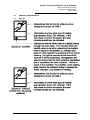
1
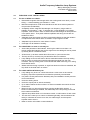
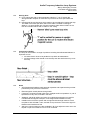
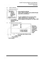
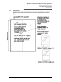
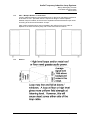
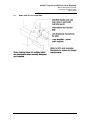
Audio Frequency Induction Loop Systems
Mervyn Willoughby Thomas
Eric Martin and Associates
March 2003
AFILS
AUDIO FREQUENCY INDUCTION LOOP SYSTEMS
MARCH 2003
1.0
INTRODUCTION
1.1
This is a simple guide for architects and others in complying with the Building Code of
Australia clause D3.7 Hearing Augmentation, initiated by the late Mervyn WilloughbyThomas FRAIA, Accredited Access Consultant with the ACAA and a hearing-impaired
architect. It assumes a knowledge of building construction standards and legislation.
1.2
Definitions and Names:
A number of terms are currently within common use within the industry to describe
the Audio Induction Loop. These terms include:
- Hearing Augmentation (includes Loop, FM, Infra Red)
- Audio Frequency Induction Loop System (AFILS)
- Powered Audio Induction Loop System (PAILS)
- Hearing Aid Loop
- Audio Loop
- Loop
- Deaf Aid Loop (NOT TO BE USED)
1.3
The DDA (Disability Discrimination Act 1992) through the BCA (Building Code of
Australia) aims to maximise participation in community life by people with disabilities.
BCA Clause D3.7 applies where there is an inbuilt amplification system (other than
emergency warning) in:
•
•
•
•
•
2
Conference and meeting rooms over 100m floor area.
Auditoria in Class 9b building, Hearing Augmentation to not less than 15% of an
auditorium.
Rooms for judicial purposes.
Ticket office, tellers booth etc where the public are screened from the servicer.
Any screen or scoreboard capable of displaying public announcements must
supplement any public address system eg captions.
(Refer to the BCA for the precise text).
1.4
The intent of this paper is to clarify some of the options which realistically meet the
BCA requirements for hearing augmentation for the majority of hearing-impaired
people.
1.5
Hearing impairment, which occurs to many people, especially if over 50 years age,
can be mild, moderate, severe or profound. Augmentation of sound will not help all of
the profoundly deaf as some have no hearing; they need subtitles or captions.
People with hearing impairment may try to compensate by using a hearing aid,
cochlear implant, or a loop receiver. If the hearing aid or cochlear implant has a T
switch, and the room has an audio loop (correctly installed, and picking up sound
from the microphone of a specific speaker or sound source, whether wired or radio)
then the background noise can be reduced or eliminated.
A loop receiver is a pocket sized device fitted with a T switch and stethoscope style
earpieces, called a stetoclip.
S:\OldServer\EMA Work\Other professional activities\MWT WORK\012003 AFILS.doc
Page 1 of 17
Audio Frequency Induction Loop Systems
Mervyn Willoughby Thomas
Eric Martin and Associates
March 2003
There are two types of background noise. The first is noise other than the signal
trying to be heard e.g. air conditioning, audience, chatter. The second type is
reverberation of the signal trying to be heard. Reverberation typically becomes an
impediment to understanding if the hearing impaired person is greater than 1.5
metres than the sound source, although the exact distance varies between individuals
and circumstances. Hence, loop systems are commonly used in lounge rooms to
assist in understanding the television. This is a clear example of the needs of hearing
impaired people for Hearing Augmentation.
For an effective AFILS system, the aim is to minimise the distance between the
source of sound and the listener.
The signal received by a hearing impaired person needs to be greater than 15 dB
above the background noise level, i.e. Signal to noise ratio, S/N = > 15dB.
1.6
A hearing impaired person can hear sounds, but their ears lose the faculty of:
•
Distinguishing the message of a specific speaker from the background noise
level,
•
Understanding the words due to reflections of the sound off walls, floors,
furnishings etc,
•
The ability to cope with changes in level of sound i.e. dynamic range.
The spoken work still needs to be clearly enunciated and not too fast. Seeing the
expression on a speaker’s face and body language is important as many use a
combination of hearing and lip reading, to reinforce the spoken message.
S:\OldServer\EMA Work\Other professional activities\MWT WORK\012003 AFILS.doc
Page 2 of 17
Audio Frequency Induction Loop Systems
Mervyn Willoughby Thomas
Eric Martin and Associates
March 2003
2.0
HEARING AUGMENTATION SYSTEMS
If the Hearing Augmentation system is incorporated with the public address system,
ensure that the Hearing Augmentation System is automatically operated with PA
announcements
In public buildings there are three options readily available:
2.1
AFILS (Audio Frequency Induction Loop System)
The loop is located in or around the room. This is suitable for most churches, lecture
theatres and auditoria, and is the preferred option for people with hearing impairment.
Generally it is also the most cost effective system.
It is estimated that 70 to 80% of hearing aids are fitted with a T switch. However, If a
hearing aid lacks a T switch, then a loop receiver with stetoclip or head phones are
required to augment the sound level for a mild or moderately hearing impaired
person. The advantage of the AFILS is the need to provide receivers only for those
without the T switch, as both other types of systems require receivers to be provided
for every user.
Electromagnetic signals can be affected by electronic apparatus and steel to varying
degrees. Electromagnetic waves also pass through walls, and hence loss of privacy
is possible. AFILS work indoors and outdoors. This is relatively cheap to provide, and
once installed requires minimal administrative assistance apart from periodic check
for being in working order.
If there are other loop systems close by, the problem of overlap of sound must be
addressed. This is a serious problem if the auditoria are next to or above one
another. There are various ways to resolve this overlap but consult the experts while
the design is still in its early stage.
There are many unsatisfactory audio-magnetic loop installations. It is an area
for the specialist, rather than the average electrical consultant or contractor.
Consultation may be necessary at the early design stage as well as when the
building is under construction.
Many telephone handsets have a coil which, with a T switch on the hearing aid, cuts
out the background noise.
One concern when installing AFILS is interference caused by electrical cabling, or in
some cases nearby electronic/electrical equipment.
2.2
FM (Frequency Modulation)
This system consists of a base station transmitter and individual receivers for each
user. Attachments are also required for each user, neck loops for users with T switch
on their hearing aids, and headphones or stetoclip for the remainder of users.
For lecture tours, the same receivers and attachments are used, but with a personal
transmitter with lapel microphone.
The Phonic Ear “Easy Listener” is an example of both the above systems; it is found
in some public galleries and museums, where the battery units can be recharged
overnight.
In FM systems radio waves pass through walls. Hence loss of privacy is possible. FM
systems may be used both indoors and outdoors.
S:\OldServer\EMA Work\Other professional activities\MWT WORK\012003 AFILS.doc
Page 3 of 17
Audio Frequency Induction Loop Systems
Mervyn Willoughby Thomas
Eric Martin and Associates
March 2003
If there are loop systems close by, the problem of overlap of sound must be
addressed. There are various ways to resolve this overlap but consult the experts
while the design is still in its early stage.
2.3
IR (Infra-Red)
Infra-red listening systems require a special headphone receiver and requires clear
path from transmitter to receiver (i.e. line of sight), unobstructed by people’s limbs
and objects, even by paper.
Attachments are also required for each user, neck loops for users with T switch on
their hearing aids, and headphones or stetoclip for the remainder of users.
Alternatively, different type of receivers may be used to achieve the same result.
Walls are a barrier and hence privacy is assured.
IR is not suitable outdoors, as sunlight disrupts the infra red signal, nor is IR suitable
in rooms with direct sunlight.
As with AFILS, IR is commonly used for hearing the television and radio in the home.
In public buildings IR is rarely used except where privacy is absolutely necessary, due
to the large radiators required rooms more than 6 metres long, line of sight
restrictions, and cost effectiveness compared to the alternatives.
If there are loop systems close by, the problem of overlap of sound must be
addressed. There are various ways to resolve this overlap but consult the experts
while the design is still in its early stage.
S:\OldServer\EMA Work\Other professional activities\MWT WORK\012003 AFILS.doc
Page 4 of 17
Audio Frequency Induction Loop Systems
Mervyn Willoughby Thomas
Eric Martin and Associates
March 2003
3.0
THE AUDIO LOOP - INSTALLATION
3.1
The aim of AFILS is to obtain:
3.2
3.3
•
Reasonable magnetic field strength within the working area at ear level (1 metre
sitting, 1.7 metre standing), per AS1088.4 – 1987.
•
Minimal overspill which could cause interference with other similar systems or
compromise confidentiality
•
Acceptably uniform magnetic field strength over frequency range 100Hz to
5000Hz, per AS1088.4 – 1987. To achieve this, current amplifiers, not voltage
amplifiers, must be used in order to obtain uniform field strength at all frequencies
in the speech band. Thus public address amplifiers and wiring circuits are not
suitable for AFILS.
•
Adequate signal processing to achieve compression/limiting so that the variation
in output level is less than 3 dB for a variation of input signal of 30 dB.
•
Adequate loop receivers for users without T switch.
•
Coverage over all classes of seating.
The LOCATION in a room or area may be:
•
Around the perimeter of the listeners, ensuring the cable is more than 0.75
metres outside the listening area, as the signal from the cabling will not be picked
up directly above or below the cable.
•
At floor level, up to three metres above floor level, or just under the floor.
•
The loop of wire (or 2 wires) may rise and fall at doors or windows.
•
Loop cabling must not have steel or ferrous materials between the loop cabling
and the users, as the ferrous materials will shield the signal from the user.
Therefore, the loop cabling must not be laid beneath steel reinforcing or in ceiling
steel channel struts.
•
Where steel reinforcing is present, or significant amounts of ferrous materials, the
loop shall not be wider than 10 metres.
The LOOP INSTALLATION may be:
•
Loop cabling may be one or 2 wires. More than 2 wires must not be used as
frequency response requirements are otherwise practically unacheivable.
•
In a plastic conduit (about 20mm diameter) with post installation access points at
corners and bends.
•
Under the skirting board.
•
Under the carpet (with or without underfelt)
•
Up to 400mm below the floor surface if no ferrous materials are used in the floor
construction
•
Must not have any other electrical wiring running parallel within 200mm. If
electric in-slab-heating is installed, the relationship of the loop wire(s) to the slab
wires needs consideration.
•
Adjacent loop cables shall run in the same conduit, or within 20mm of each other.
•
2
The size of the cable (0.5 to 2.5mm multistrand generally, but sometimes a flat
cable) is calculated to suit the room size, the cable length, and the specific
amplifier used to drive it..
•
Refer to Section 6 for tellers counter situations.
S:\OldServer\EMA Work\Other professional activities\MWT WORK\012003 AFILS.doc
Page 5 of 17
Audio Frequency Induction Loop Systems
Mervyn Willoughby Thomas
Eric Martin and Associates
March 2003
4.0
GENERAL REQUIREMENTS
4.1
Signage
S:\OldServer\EMA Work\Other professional activities\MWT WORK\012003 AFILS.doc
Page 6 of 17
Audio Frequency Induction Loop Systems
Mervyn Willoughby Thomas
Eric Martin and Associates
March 2003
4.2
Hearing Aids
a) For a hearing aid with an electromagnetic induction ‘T’ coil (T switch) the
strongest audio reception is within the loop but there is some spill outside the
loop.
b) Hearing aids have a blind spot which needs to be considered in locating the loop.
The width of the blind spot either side of the cable is variable according to
distance. An approximate rule of thumb is 500mm either side of cable if in the
floor and 1000mm either side of cable if in the ceiling.
4.3
Construction Details.
The loop can be located in a range of positions including those illustrated below it is
important to note.
• No other electric wires to be parallel to loop within at least 200mm.
• No High Voltage wires should cross the loop area but 240V wires may cross
the loop.
4.4
Notes
•
AFILS designers/installers need particular expertise and experience beyond that
practised by many electrical contractors.
•
Electromagnetic sound passes through walls.
•
If security is required consider infra-red or multiple small loud speakers i.e. pair of
speakers for every seat, mounted in the seat.
•
Steelwork, electrical cabling and some air conditioning equipment can result in
unusable electromagnetic reception if not designed and installed correctly.
•
Installers must check the system with a magnetic field strength meter to check
compliance with AS1088.4.1987, and with a loop receiver to ensure the signal is
distortion and interference free
•
Spill-over control systems are also available if all of two adjacent rooms are to be
looped or spill-over outside a room is to be controlled.
S:\OldServer\EMA Work\Other professional activities\MWT WORK\012003 AFILS.doc
Page 7 of 17
Audio Frequency Induction Loop Systems
Mervyn Willoughby Thomas
Eric Martin and Associates
March 2003
This is achieved by additional active loops to resolve interference. However, this
is usually at a significant cost.
S:\OldServer\EMA Work\Other professional activities\MWT WORK\012003 AFILS.doc
Page 8 of 17
Audio Frequency Induction Loop Systems
Mervyn Willoughby Thomas
Eric Martin and Associates
March 2003
5.0
LOOP LOCATIONS
5.1
Small Rooms 100-200 m2
5.2
Long Rooms if two loops installed
S:\OldServer\EMA Work\Other professional activities\MWT WORK\012003 AFILS.doc
Page 9 of 17
Audio Frequency Induction Loop Systems
Mervyn Willoughby Thomas
Eric Martin and Associates
March 2003
5.3
Large Rooms
The loop should include all the auditorium area but in larger auditoria or in multiple
auditoria the loop is recommended to be on one side in preference to the back or
front.
S:\OldServer\EMA Work\Other professional activities\MWT WORK\012003 AFILS.doc
Page 10 of 17
Audio Frequency Induction Loop Systems
Mervyn Willoughby Thomas
Eric Martin and Associates
March 2003
5.4
Plan – Multiple Rooms on same level
Loops in adjacent areas are recommended to be on the left or right side in preference
to the back or front. Specialist advice is required in design to ensure spillover
between loops is avoided, as the minimum separation distance between loops varies
according to the size and orientation of loops.
Care is also required when a loop is installed in the ceiling of one room under or
adjacent to an area covered by loop, FM or infra-red on the floor above.
5.5
Section
S:\OldServer\EMA Work\Other professional activities\MWT WORK\012003 AFILS.doc
Page 11 of 17
Audio Frequency Induction Loop Systems
Mervyn Willoughby Thomas
Eric Martin and Associates
March 2003
6.0
BANK AND TELLER COUNTERS
S:\OldServer\EMA Work\Other professional activities\MWT WORK\012003 AFILS.doc
Page 12 of 17
Audio Frequency Induction Loop Systems
Mervyn Willoughby Thomas
Eric Martin and Associates
March 2003
7.0
LOOP AMPLIFIER – MINIMUM REQUIREMENTS
NOTES
1.
Loop amplifiers must use current instead of voltage for adequate reception through
out the speech range (100 Hertz to 5000 Hertz), which is important for intelligibility of
speech.
2.
Allow for ventilation of loop amplifiers.
3.
Loop wire(s) varies form 0.5mm to 2.5 mm diameter or can be a flat cable 18 mm
wide to suit room size.
4.
The Amplifier may be fed with the signal from a wired or radio microphone, or an
output from a PA system.
5.
After correct installation of the loop system it needs checking for magnetic field
strength, frequency response and clarity.
The signal to noise ratio must be within prescribed limits for clarity and effectiveness.
A calibrated field strength tester and a loop receiver are required to for testing the
AFILS.
Further adjustments later are rarely necessary, but absolutely necessary if the PA
system is modified.
6.
A written user manual related to the system installed is necessary.
It should show how to operate the system, the location of loop cable, its diameter and
the measuring data (Note 5 above).
7.
Building owners without a hearing loss can verify loop operation on an ongoing basis
using the loop receivers provided for hearing impaired users without T switch.
S:\OldServer\EMA Work\Other professional activities\MWT WORK\012003 AFILS.doc
Page 13 of 17
Audio Frequency Induction Loop Systems
Mervyn Willoughby Thomas
Eric Martin and Associates
March 2003
8.0
REFERENCES AND CONTACTS
8.1
Sources of Information
• PrintAcall Loop information catalogue
• Sensory Access Seminar by Peter Kerley. Oct 2000 for Standards Australia
• Paper by Ref Siegried Karg at International Congress of Hard of Hearing People,
Sydney, Australia, July 2000 courtesy of Better Hearing, March 2001.
• Deafness Resource Guide 2000-2001 by Deafness Resources Australia
• British Standard, BS 7594:1993
• Australian Standard, AS1088.4 – 1987
• Australian Standard, AS1428.1 and 1428.2
Acknowledgement and thanks also to SHHH Australia Inc, Ray Piesse, Peter Cianchi,
Andrew Stewart, Glen Thurecht, Eric Martin and others, Many thanks.
8.2
8.3
Organisations who can assist:
• PrintAcall
2 Doig Ave, Denistone East, NSW 2112
• Deafness Forum of Australia
218 Northbourne Avenue, Braddon, ACT 2612
• Deafness Resources Australia
33 Argyle Street Parramatta, NSW 2150
• SHHH Australia Inc (Self Help for Hard of Hearing People)
1334 Pacific Highway, Turramurra, NSW 2074
• Better Hearing Australia Inc
54 Hyman Avenue, Edwards Town, SA 5035
• Word of Mouth
27 MacAuley Place, Bayswater, VIC 3153
Some experienced installers include:
• PrintAcall
NSW, ACT, Qld, Vic
• GPT Designs
Canberra
• Word of Mouth
Melbourne
tel: (02) 9809 2392
tel: (02) 6262 7808
tel: (02) 9895 2970
tel: (02) 9144 7586
tel: (08) 8297 3078
tel: (03) 9729 9974
Andrew Stewart tel: (02) 9809 2392
Glen Thurich tel: (02) 6286 9600
Bob Willis
tel: (03) 9729 9974
8.4
Some specialist suppliers are:
• Ampetronic Ltd (UK) for Phase Array Spill-over Control
• Oval Window Audio Nedland, Colorado, USA for 3D loop system spill-over control
• PrintAcall for multiple layout design systems
8.5
Outline Specification
An outline specification for the design and installation of a hearing augmentation
listening system is included as Attachment A
NOTE: This report was initially prepared by Mervyn Willoughby -Thomas (an ACT architect
and access consultant who had a hearing impairment), but unfortunately Mervyn died
before he could complete this paper. Its completion by ACT ACROD Access &
Mobility Committee under the guidance of Eric Martin is in part of tribute to Mervyn’s
dedication and commitment to improving access especially for hearing impaired.
Special thanks are extended to Andrew Stewart from PrintAcall for his advice and
editorial assistance in finalising this advice.
March 2003
S:\OldServer\EMA Work\Other professional activities\MWT WORK\012003 AFILS.doc
Page 14 of 17
Audio Frequency Induction Loop Systems
Mervyn Willoughby Thomas
Eric Martin and Associates
March 2003
ATTACHMENT A – OUTLINE SPECIFICATION
HEARING AUGMENTATION LISTENING SYSTEM
General
Provide a hearing augmentation listening system for hearing impaired people in the
room.
The hearing augmentation listening system shall be an audio frequency induction
loop system consisting of a:
•
Loop amplifier
•
Loop cable
•
Test Receiver
•
Loop Receivers
•
Other equipment as required.
Subcontractor
The hearing augmentation listening system shall be installed by a specialist
subcontractor with experience in installing audio frequency induction loop system
Standards – Loop Amplifier
- Transconductance Amplifier
- Output Current of 10 Amps continuous into 2 ohms
- Input compression of 30dB input: 1dB output.
- Balanced Microphone input, with switchable phantom power
- Balanced Line input
- Output metering:
- Bar graph for output signal
- Separate indication for threshold of compression
- Separate indication for 8 to 10dB into compression
- Total harmonic distortion 0.5%
- Frequency response 3dB 100Hz – >5kHz
- Min 6dB per octave roll off from 6kHz
- Short circuit protection
- Size is two rack units (2RU), and allow one rack unit for ventilation.
Connection
The input of the loop amplifier shall be connected to the:
- line output of the public address system (when a public address system is
supplied by others)
- audio out of the television (when a television is supplied or expected to be
supplied)
- output of the radio microphone receivers (one UHF diversity lapel radio
microphone system and one UHF handheld diversity radio microphone system to
be supplied by the Hearing Augmentation subcontractor when no public address
system is supplied by others)
Location
The loop amplifier shall be located in the public address system rack (rack with
adequate space to be provided by others, where a public address system is
provided).
The loop amplifier shall be located in a vertical wall mount cupboard (vertical wall
mount cupboard to be supplied by the Hearing Augmentation subcontractor when no
public address system is supplied by others).
Loop
The loop shall comprise insulated Figure 8 cable with a continuous colour
S:\OldServer\EMA Work\Other professional activities\MWT WORK\012003 AFILS.doc
Page 15 of 17
Audio Frequency Induction Loop Systems
Mervyn Willoughby Thomas
Eric Martin and Associates
March 2003
identification stripe along the entire length of the cable. The colour identification stripe
to be of a different colour to the insulation colour. The loop cable resistance shall be
matched to the loop amplifier, and this cable shall be specified and supplied by the
loop subcontractor.
Where a wooden floor is to be installed on a concrete floor;
Install the loop adjacent to and within 200mm of the perimeter walls of the …. room
above concrete slab and below false flooring. Notch flooring battens to allow loop
installation.
Where a concrete floor is to be covered directly with the flooring ;
Install the loop adjacent to and within 200mm of the perimeter walls of the …. room,
in the concrete slab, above all steel reinforcing
The loop cable shall be continuous without joints or connections.
The loop cable to be installed in 19mm conduit with draw-in boxes located on the …
room perimeter walls. Label wall boxes ‘AUDIO LOOP SYSTEM’.
The loop cable shall be wired to provide two complete, consecutive turns and have a
total resistance of between two and three ohms.
Notices
Provide the international symbol for deafness in a prominent position in the … room
indicating that an assistive hearing device is installed. The symbol to comply with AS1428.2 symbols. The size of the sign is to be a minimum of A4.
Provide a notice adjacent to the amplifier detailing how the system works and the
procedures for testing the system.
Test Devices
Provide one test receiver.
Provide two loop receivers for hearing impaired users with hearing aids. The number
to be supplied is five percent of the maximum number of people to be in the looped
area at one time. Loop receivers are to be supplied with one stetoclip with each
receiver.
Provide Training and Instruction Manual
Provide staff training to make staff aware of how the system works and the need to
have it turned on and tested regularly.
Testing and Commissioning
Carry out a commissioning with a hearing aid to test clarity of speech, music and for
interference at the weakest point.
Check field strength with a calibrated field strength meter to be a minimum of 0.1 A/m,
with the output current as a 1 kHz sinusoidal wave, and measured in the weakest
place inside the loop.
Check loop current for compliance with the frequency response of 100Hz – 5kHz, and
roll off of at a minimum of 6dB per octave above 6kHz.
Check compression of 30 dB, and that the threshold of compression is set for soft
speech.
A procedure for routinely testing and monitoring, using a loop receiver, shall be
detailed and staff trained in its use. The procedure shall include testing the level of
the loop system and listening to the clarity of speech and music through the system.
S:\OldServer\EMA Work\Other professional activities\MWT WORK\012003 AFILS.doc
Page 16 of 17
Audio Frequency Induction Loop Systems
Mervyn Willoughby Thomas
Eric Martin and Associates
March 2003
Signage
Supply and install signage to AS1428.1 at the entry of the room and at the front of the
room.
S:\OldServer\EMA Work\Other professional activities\MWT WORK\012003 AFILS.doc
Page 17 of 17