1
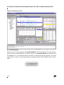
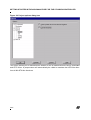
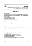
AN1369 APPLICATION NOTE GETTING STARTED WITH RAISONANCE IDE FOR THE ST6 MICROCONTROLLER by Microcontroller Division Applications INTRODUCTION Ride is the development toolchain for ST62 developed by Raisonance. This fully Integrated Development Environment supports all the ST62 microcontroller family and features a powerful macro-assembler, a linker, a C compiler and a state-of-the-art simulator and debugger. It can drive the ST6-HDS2, CEIBO EB-ST62 and SOFTEC DS6225A & DS6265A emulators. You can install the evaluation version from either the “MCU ON CD” CD-ROM or directly from the Raisonance website: http://www.raisonance.com. This tutorial has been extracted from the User Manual of the ST6 Evaluation Board, ST6-Eval, available on either the “MCU ON CD” CD-ROM or on the ST MCU website http://mcu.st.com. For more information about Raisonance IDE, please contact Raisonance at http://www.raisonance.com and to get other program examples, please refer to the ST6 Evaluation Board Manual. Note: The corresponding source files are provided in a downloadable .ZIP file along with this note on the ST MCU website http://mcu.st.com The goal of this application note is to help you get started with the Raisonance IDE environment using an example program tutorial.st6 located in the directory .\Exercises\Tutorial. The exercise will make you familiar with the project management, the assembler syntax and debugging using the Raisonance IDE. The aim of the tutorial.st6 program is to make two LEDs blink at a frequency of 1Hz, simply using the I/O Ports. It assumes that the LEDs are connected to port PA0 and PA1 of the ST6265C device and are active low. AN1369/0901 1/23 1 Table of Contents 1 PROJECT SETUP . . . . . . . . . . . . . . . . . . . . . . . . . . . . . . . . . . . . . . . . . . . . . . . 3 2 EDITING THE CODE . . . . . . . . . . . . . . . . . . . . . . . . . . . . . . . . . . . . . . . . . . . . . 5 3 COMPILING THE CODE . . . . . . . . . . . . . . . . . . . . . . . . . . . . . . . . . . . . . . . . . . 6 4 STARTING A DEBUG SESSION . . . . . . . . . . . . . . . . . . . . . . . . . . . . . . . . . . . . 7 4.1 STEPPING THROUGH THE CODE . . . . . . . . . . . . . . . . . . . . . . . . . . . . . . 9 4.2 RUNNING THE CODE . . . . . . . . . . . . . . . . . . . . . . . . . . . . . . . . . . . . . . . . 9 4.3 SETTING A BREAKPOINT . . . . . . . . . . . . . . . . . . . . . . . . . . . . . . . . . . . 10 4.4 WATCHING A VARIABLE . . . . . . . . . . . . . . . . . . . . . . . . . . . . . . . . . . . . 10 4.5 VIEWING THE PERIPHERALS OR THE ST6 REGISTERS . . . . . . . . . . 12 4.6 TIME FEATURE . . . . . . . . . . . . . . . . . . . . . . . . . . . . . . . . . . . . . . . . . . . . 13 4.7 ADVANCED FEATURES . . . . . . . . . . . . . . . . . . . . . . . . . . . . . . . . . . . . . 14 4.7.1 4.7.2 4.7.3 4.7.4 4.7.5 Trace window . . . . . . . . . . . . . . . . . . . . . . . . . . . . . . . . . . . . . . . . . . Refresh feature . . . . . . . . . . . . . . . . . . . . . . . . . . . . . . . . . . . . . . . . Animate Mode . . . . . . . . . . . . . . . . . . . . . . . . . . . . . . . . . . . . . . . . . Disassembly code window . . . . . . . . . . . . . . . . . . . . . . . . . . . . . . . . External interrupt window . . . . . . . . . . . . . . . . . . . . . . . . . . . . . . . . 14 16 18 19 20 5 ENABLING AST6/LST6 RIDE COMPATIBILITY . . . . . . . . . . . . . . . . . . . . . . . 21 23 2/23 2 GETTING STARTED WITH RAISONANCE IDE FOR THE ST6 MICROCONTROLLER 1 PROJECT SETUP 1. Start the Raisonance IDE: from the Windows Start menu, select Start > Programs > Raisonance Kit 6.1> Ride IDE. 2. Now you need to create a new project environment. The project file stores all the parameters of the project: settings, options, and all the files that have to be included to the project. To create a new project, go to the Project menu and click on New. The dialog box shown in Figure 1 will appear. Figure 1. New project dialog box 3. Click on Browse to find the path where you want to create your project and name it (e.g. tutorial.prj). Click on the OK button to validate the creation of the project. 4. Now you have a new window (Project >Debugger) with the name of your new project. Click on it with the right mouse button. A menu shown in Figure 2 will be displayed. 3/23 GETTING STARTED WITH RAISONANCE IDE FOR THE ST6 MICROCONTROLLER Figure 2. New Project Menu 5. Click on Add node Source/Application (or find it in the Project menu) to add the file you want to work on. Choose the tutorial.st6 assembly file located int the .\Exercises\Tutorial. When you select this file, it will display the file code and you will also be able to see it in the project window as shown below. Figure 3. Project tree 6. You HAVE TO specify the target option before compiling any program. This defines the microcontroller used to run the program. Click on the Options > Target menu and choose the microcontroler you are working with (the ST6265C in this case). Click OK to validate the selection. 4/23 GETTING STARTED WITH RAISONANCE IDE FOR THE ST6 MICROCONTROLLER Figure 4. Type of project dialog box Now the project environment is set up and you can start playing with the code. 2 EDITING THE CODE You can now start correcting the file! You will have to fill in the blanks next to the question marks. Before you start work, here is a brief explanation of the toolbar. Figure 5. Editing toolbar This is a list of the actions invoked by each toolbar icon from left to right: – Open a file in the editor Note: Be aware that this only opens a file. It doesn’t open a project (to do that you have to select Project > Open) and it doesn’t add the file to the project automatically (to do that you have to select Project > Add node Source/application). – Save the changes you made to your file – Tile the windows vertically – Enter Debug mode – Compile (Translate) the single file that is activated or the one that is selected in the Project View window. – Compile (Make all) all the files of the project (recommended) 5/23 GETTING STARTED WITH RAISONANCE IDE FOR THE ST6 MICROCONTROLLER – Undo command – Cut command – Copy command – Paste command – Find an expression in the file – Find the Next same expression 3 COMPILING THE CODE A good way to get familiar with RIDE is to start compiling your program before making any corrections and, then, to correct the errors little by little. 1. Click on the Make all icon to compile the assembly file. A new window will now appear like that shown in Figure 6. This window shows you the errors and the warnings the compiler generated and displays the results of the compilation. Figure 6. Errors and warnings in the Make window 2. Double-click on the warning or error messages to see the line of the program related to the message. The corresponding line in the program window will be highlighted. 3. Start correcting the errors. Once you have finished, you can save your changes by clicking on the Save icon or on the menu File >Save. Compile the file again until you made the right corrections, that is to say when no error messages appear anymore. Figure 7 shows the window you will get at this point. 6/23 GETTING STARTED WITH RAISONANCE IDE FOR THE ST6 MICROCONTROLLER Figure 7. Successful Make window 4 STARTING A DEBUG SESSION In the last section the only thing we did was to compile, i.e. to make sure the program had the right syntax and the right structure. We now have to check if it really does what we want it to do. This is the debug phase. This will be done by using the Raisonance simulator to simulate the behaviour of the microcontroller. 1. Click on the Debug icon to enter debug mode. The following dialog box will appear: Figure 8. Debug options dialog box When you click on Options > Debug you can select the type of debug you want to do. Select Virtual Machine (Simulator) then SIM-ST6 and click on the OK button. 7/23 GETTING STARTED WITH RAISONANCE IDE FOR THE ST6 MICROCONTROLLER Figure 9. Simulator Environment In this environment you have several tools to help you to simulate and view what the program does. Let’s have a look at the Debug toolbar: Figure 10. Debug Toolbar Here is a list of the actions invoked by the toolbar icons from left to right: – Enable Animated Mode – Display executed lines. Each line containing an instruction in the program is indicated with a green dot. If you press this icon, the green dot next to the executed line becomes blue. – Refresh command. 8/23 GETTING STARTED WITH RAISONANCE IDE FOR THE ST6 MICROCONTROLLER – Reset command. This button corresponds exactly to a hardware RESET. – Execute each line and each function routine step by step (step into). – Execute each line step by step (step over). – Add the watch window. – Add a toggle breakpoint at the selected line of the program. Click again to disable the breakpoint. – Add a toggle trace at the selected line of the program. Click again to disable the toggle trace. – Select the file you want to debug. – Run the application. If Animated Mode is selected, it runs the application at a set speed that can be selected with the next icon. Otherwise it runs the application in real-time. – Set the execution speed of the application in Animated Mode. 4.1 STEPPING THROUGH THE CODE Execute the program step by step using the step over icon. Each time you click on this icon you will see the current line changing to the next program instruction. At each step you are then able to look at the state of the microcontroller, as explained later on. Note: The step into icon allows you to enter the function subroutines. It is not likely that you will need this feature at the beginning. Furthermore this is a rather tedious way of following the execution of the program, because you really step through all the functions. 4.2 RUNNING THE CODE You can also run the program directly using the Run icon. Click once on the icon: it will run the application and the icon will change to Click on the icon again and the application is stopped. Note at the bottom of the Debug window the period of time spent running the application. 9/23 GETTING STARTED WITH RAISONANCE IDE FOR THE ST6 MICROCONTROLLER 4.3 SETTING A BREAKPOINT Restart the program by selecting the Debug >Restart menu. Click on the vertical bar on the left side of the program window in front of the line where you want to place the breakpoint. The line will be highlighted in red and the next time you run the application, the program counter (PC) will stop at the breakpoint. Figure 11. Set breakpoint To delete the breakpoint simply click on the red S sign again. 4.4 WATCHING A VARIABLE Click on Debug >Add Watch. A dialog box will appear: it allows you to select the registers, labels or variables you want to watch from a list of expressions. Type PA.0 and click on the OK button. Figure 12. Add watch dialog box 10/23 GETTING STARTED WITH RAISONANCE IDE FOR THE ST6 MICROCONTROLLER Then the following window will appear. It stores all the expressions you need. Figure 13. Watch window Now click with the right button of your mouse on the Watch Window and select Add. This opens the Add Watch Dialog Box again. Type PA.1 and click on the OK button. Figure 14. Watch window 11/23 GETTING STARTED WITH RAISONANCE IDE FOR THE ST6 MICROCONTROLLER 4.5 VIEWING THE PERIPHERALS OR THE ST6 REGISTERS In the Debugger window you can see all the microcontroller’s registers and peripherals. Figure 15. Debugger window Double-click on any of the items and you will be able to view their state at any time during debugging. Figure 16 shows the window that will be displayed when you double-click on the PA icon. 12/23 GETTING STARTED WITH RAISONANCE IDE FOR THE ST6 MICROCONTROLLER Figure 16. Port A window Figure 17 shows the window that will be displayed when you double-click on the Main Registers icon. Figure 17. Main registers window To watch the values of certain registers only, the address of the labels or the value of the possible variables, you have to open the Watch Window. 4.6 TIME FEATURE If you want to determine the time spent for one or several instructions of your program, set breakpoints at the first and last instruction. Run your program with the Run icon. It will stop at the first breakpoint. Then select the Debug > Reset Time menu (you can also use the macro Ctrl + T). The displayed time is reset. If you click on the Run icon again, it will display the time spent executing the instructions. 13/23 GETTING STARTED WITH RAISONANCE IDE FOR THE ST6 MICROCONTROLLER 4.7 ADVANCED FEATURES 4.7.1 Trace window An easy way to see how the program is executed is to trace the state of the PA0 and PA1 ports. You should be able to see the value toggling from 1 to 0 and 0 to 1 every 0.5s. Keep the Watch Window open, select PA.0 and click on the right mouse button. The following menu will appear: Figure 18. Add/Delete from Trace List Select the Add/Delete from Trace List item and a blue “T” will be displayed in front of PA.0. This will allow you to watch the trace of the PA0 pin (you can do the same for PA1) in the Trace Window. Figure 19. PA0 and PA1 Toggle Trace Then select the View >Trace >Options menu to set the Trace Options dialog box. Then click on the On Changes radio button. The trace will be updated each time the value of the selected item is changed. 14/23 GETTING STARTED WITH RAISONANCE IDE FOR THE ST6 MICROCONTROLLER You can also change the maximum number of records that can be displayed in the Trace window. Validate the choice with the OK button. Figure 20. Trace Options dialog box Click now on the View >Trace >View menu to open the trace window. 15/23 GETTING STARTED WITH RAISONANCE IDE FOR THE ST6 MICROCONTROLLER Figure 21. Trace window 4.7.2 Refresh feature Now insert a refresh tag so the window will be refreshed each time the instruction, where it is placed, is processed. Place it at the program line where the “TOGGLE” label is located so that the trace will be regenerated at each commutation of the pin. To do this, click on the source code line containing the ”TOGGLE” label (so that the cursor blinks), and click on the left margin with the right mouse button. The following menu on the next page appears. 16/23 GETTING STARTED WITH RAISONANCE IDE FOR THE ST6 MICROCONTROLLER Figure 22. Left margin menu Select Toggle Flag >Toggle refresh and a small light bulb icon will appear in front of the line as follows: Figure 23. Toggle refresh mark At this point, you may want to resize the windows in the screen to have a clear view if what happens when you run the application. You can use the Tile Vertical icon for example. Now, click on the Run icon and watch the program working! Figure 24 on the next page shows an example of the debug screen you can have. 17/23 GETTING STARTED WITH RAISONANCE IDE FOR THE ST6 MICROCONTROLLER Figure 24. Debug overview 4.7.3 Animate Mode Finally, you can run the program using Animated Mode. This mode allows you to see the program execute at a desired speed. To do this, click on the Animated Mode icon and then click on the Run icon. You should be able to see the PC running through the program. To set the speed faster or slower, use the speed slider, and drag the index to the desired position on the scale. 18/23 GETTING STARTED WITH RAISONANCE IDE FOR THE ST6 MICROCONTROLLER 4.7.4 Disassembly code window You can open the Disassembly code window by selecting the corresponding icon in the Project > Debugger window. Figure 25. Disassembly code window You can then check the code at each address of the program memory area. Each line of the program is displayed with its address, the label if applicable (Symbol), the op-code actually executed (Mnemonic), and the number of times the PC executed the line. 19/23 GETTING STARTED WITH RAISONANCE IDE FOR THE ST6 MICROCONTROLLER 4.7.5 External interrupt window You get the Interrupt Controller window after selecting the corresponding icon in the Project - Debugger window. Figure 26. Interrupt controller window This window enables you to check whether each interrupt is enabled or not. Now it’s up to you if you want to make changes to the program (e.g. change the value of COUNTER to modify the delay) or to test the different features of RIDE. To exit debug mode and return to edit mode, select the Debug >Terminate menu. 20/23 GETTING STARTED WITH RAISONANCE IDE FOR THE ST6 MICROCONTROLLER 5 ENABLING AST6/LST6 RIDE COMPATIBILITY RIDE is able to process AST6/LST6 files. If you want to use them, select Options >Project and the following dialog box will appear. Figure 27. Project options dialog box Then, double-click on MAST6 > source and check the Use AST6 syntax check box: as shown on the next page. 21/23 GETTING STARTED WITH RAISONANCE IDE FOR THE ST6 MICROCONTROLLER Figure 28. Project options dialog box This option allows you to assemble files written for the STMicroelectronics AST6 assembler and LST6 linker. A preprocessor will automatically be called to translate the AST6-like directives in MA-ST6-like directives. 22/23 GETTING STARTED WITH RAISONANCE IDE FOR THE ST6 MICROCONTROLLER “THE PRESENT NOTE WHICH IS FOR GUIDANCE ONLY AIMS AT PROVIDING CUSTOMERS WITH INFORMATION REGARDING THEIR PRODUCTS IN ORDER FOR THEM TO SAVE TIME. AS A RESULT, STMICROELECTRONICS SHALL NOT BE HELD LIABLE FOR ANY DIRECT, INDIRECT OR CONSEQUENTIAL DAMAGES WITH RESPECT TO ANY CLAIMS ARISING FROM THE CONTENT OF SUCH A NOTE AND/OR THE USE MADE BY CUSTOMERS OF THE INFORMATION CONTAINED HEREIN IN CONNEXION WITH THEIR PRODUCTS.” Information furnished is believed to be accurate and reliable. However, STMicroelectronics assumes no responsibility for the consequences of use of such information nor for any infringement of patents or other rights of third parties which may result from its use. No license is granted by implication or otherwise under any patent or patent rights of STMicroelectronics. Specifications mentioned in this publication are subject to change without notice. This publication supersedes and replaces all information previously supplied. STMicroelectronics products are not authorized for use as critical components in life support devices or systems without the express written approval of STMicroelectronics. The ST logo is a registered trademark of STMicroelectronics 2001 STMicroelectronics - All Rights Reserved. Purchase of I2C Components by STMicroelectronics conveys a license under the Philips I2C Patent. Rights to use these components in an I2C system is granted provided that the system conforms to the I2C Standard Specification as defined by Philips. STMicroelectronics Group of Companies Australia - Brazil - China - Finland - France - Germany - Hong Kong - India - Italy - Japan - Malaysia - Malta - Morocco - Singapore - Spain Sweden - Switzerland - United Kingdom - U.S.A. http://www.st.com 23/23